EP2286254B1 - Test assembly for AC testing of high voltage electrical components - Google Patents
Test assembly for AC testing of high voltage electrical components Download PDFInfo
- Publication number
- EP2286254B1 EP2286254B1 EP09761392A EP09761392A EP2286254B1 EP 2286254 B1 EP2286254 B1 EP 2286254B1 EP 09761392 A EP09761392 A EP 09761392A EP 09761392 A EP09761392 A EP 09761392A EP 2286254 B1 EP2286254 B1 EP 2286254B1
- Authority
- EP
- European Patent Office
- Prior art keywords
- voltage
- test
- container
- arrangement according
- test arrangement
- Prior art date
- Legal status (The legal status is an assumption and is not a legal conclusion. Google has not performed a legal analysis and makes no representation as to the accuracy of the status listed.)
- Active
Links
- 238000012360 testing method Methods 0.000 title claims abstract description 111
- 238000002955 isolation Methods 0.000 claims description 11
- 238000009413 insulation Methods 0.000 claims description 5
- 230000008859 change Effects 0.000 claims description 2
- 238000000926 separation method Methods 0.000 claims 1
- 230000001012 protector Effects 0.000 abstract 1
- 238000011156 evaluation Methods 0.000 description 2
- 238000000034 method Methods 0.000 description 2
- 230000008569 process Effects 0.000 description 2
- 230000008707 rearrangement Effects 0.000 description 2
- 230000003068 static effect Effects 0.000 description 2
- 230000032683 aging Effects 0.000 description 1
- 230000001419 dependent effect Effects 0.000 description 1
- 238000013461 design Methods 0.000 description 1
- 238000001514 detection method Methods 0.000 description 1
- 238000010586 diagram Methods 0.000 description 1
- 238000006073 displacement reaction Methods 0.000 description 1
- 238000010292 electrical insulation Methods 0.000 description 1
- 230000005484 gravity Effects 0.000 description 1
- 238000009434 installation Methods 0.000 description 1
- 238000012423 maintenance Methods 0.000 description 1
- 238000005259 measurement Methods 0.000 description 1
- 230000007246 mechanism Effects 0.000 description 1
- 230000001105 regulatory effect Effects 0.000 description 1
- 230000008439 repair process Effects 0.000 description 1
Images

Classifications
-
- G—PHYSICS
- G01—MEASURING; TESTING
- G01R—MEASURING ELECTRIC VARIABLES; MEASURING MAGNETIC VARIABLES
- G01R31/00—Arrangements for testing electric properties; Arrangements for locating electric faults; Arrangements for electrical testing characterised by what is being tested not provided for elsewhere
- G01R31/50—Testing of electric apparatus, lines, cables or components for short-circuits, continuity, leakage current or incorrect line connections
- G01R31/58—Testing of lines, cables or conductors
-
- G—PHYSICS
- G01—MEASURING; TESTING
- G01R—MEASURING ELECTRIC VARIABLES; MEASURING MAGNETIC VARIABLES
- G01R31/00—Arrangements for testing electric properties; Arrangements for locating electric faults; Arrangements for electrical testing characterised by what is being tested not provided for elsewhere
- G01R31/12—Testing dielectric strength or breakdown voltage ; Testing or monitoring effectiveness or level of insulation, e.g. of a cable or of an apparatus, for example using partial discharge measurements; Electrostatic testing
- G01R31/1227—Testing dielectric strength or breakdown voltage ; Testing or monitoring effectiveness or level of insulation, e.g. of a cable or of an apparatus, for example using partial discharge measurements; Electrostatic testing of components, parts or materials
-
- G—PHYSICS
- G01—MEASURING; TESTING
- G01R—MEASURING ELECTRIC VARIABLES; MEASURING MAGNETIC VARIABLES
- G01R31/00—Arrangements for testing electric properties; Arrangements for locating electric faults; Arrangements for electrical testing characterised by what is being tested not provided for elsewhere
- G01R31/50—Testing of electric apparatus, lines, cables or components for short-circuits, continuity, leakage current or incorrect line connections
- G01R31/62—Testing of transformers
-
- H—ELECTRICITY
- H01—ELECTRIC ELEMENTS
- H01F—MAGNETS; INDUCTANCES; TRANSFORMERS; SELECTION OF MATERIALS FOR THEIR MAGNETIC PROPERTIES
- H01F27/00—Details of transformers or inductances, in general
- H01F27/40—Structural association with built-in electric component, e.g. fuse
- H01F27/402—Association of measuring or protective means
Definitions
- the invention relates to a test arrangement for AC testing of electrical high voltage components with at least one inverter, with at least one test transformer, with at least one high voltage choke and with at least one other high voltage component as test components, wherein at least said test components are arranged in a common cuboid container.
- Components such as power transformers have a very high weight, depending on the electrical rating also over 100t.
- a transport of such installed within an electrical power distribution network power transformer in a permanently installed test field, in which this could be checked by means of an AC test, is usually not useful due to the high transport costs for the respective power transformer.
- the test arrangement with alternating voltage generator and other required for the test high-voltage components such as high-voltage inductor, voltage dividers, measuring devices but also with low-voltage components such as evaluation devices is transported in several modules to the place where the power transformer to be tested, and mounted there to form a test arrangement.
- the high-voltage choke which is required for a resonance test to form a resonant circuit with the test specimen, can represent a test component of considerable size with a height of, for example, 2.5 m and an inner diameter of, for example, 1 m.
- the voltage divider which is needed to measure the high voltages of, for example, up to several 100kV in the resonant circuit, is a high voltage component of similar magnitude.
- the disadvantage is that the assembly of the various modules on site is associated with a considerable amount of time.
- the positioning and mounting of a high-voltage choke or a voltage divider are very time-consuming.
- test arrangement having the features specified in claim 1.
- the at least one high-voltage choke is at least partially movable out of it by means of a movement device through at least one opening on a boundary surface of the container and that the at least one further high-voltage component within the cuboid container can be moved from a transport position into a working position.
- High-voltage components are to be understood as meaning those electrical components which can be electrically interconnected in the test arrangement. These are, for example, elements of a resonant circuit such as inductance, capacitance or resistance, but also any measuring devices such as current and voltage transformers or voltage arresters, which may be necessary for protection purposes.
- the test arrangement is not necessarily interconnected only as a single-phase resonant circuit but also as a three-phase test circuit for phased testing of a test specimen as a power transformer, but not as resonant circuits and therefore with a lower voltage, for example, 110kV.
- the Hochputsprüfkomponenten should be kept in each case three times, in particular the inverter, the test transformer, which transmits the voltage generated by the inverter to a higher voltage level, and the voltage converter.
- the insulation distances between the high-voltage choke and other adjacent high-voltage components or adjacent ground potential can advantageously be increased by moving the at least one further high-voltage component from a transport position to a working position.
- a transport position the high-voltage throttle within the container is given a particularly space-saving arrangement, which simplifies the transport of the test arrangement.
- the insulation distances are increased, which allows the operation of the arrangement or at least made more secure isolation technology.
- the change between the arrangement variants takes place by the movement device, for example a telescope-like rail, in a particularly simple form.
- a free space has formed within the container.
- This is used according to the invention by a rearrangement of selected further electrical high-voltage components of the test arrangement.
- the test components during transport of the test arrangement are compact and can be arranged without consideration of insulation distances within the cuboid container in the transport position.
- the throttle is first moved out of the container. Thereafter, the resulting space is used by an isolation-oriented arrangement of other high-voltage components, which is determined by their respective operating position.
- the space released by the moved-out throttle is not necessarily used by a rearrangement of the further high-voltage components, but that the further components in transport position allow a free space in the interior of the container, which then serves as storage space for example also needed small components is used.
- the small components are removed from the storage space and there is the isolation-oriented arrangement of the other high-voltage components.
- a transport of the container or the test arrangement is simplified by the compact arrangement of the throttle and the other high-voltage components within the container.
- the at least one further high-voltage component is an electrical filter element.
- filter elements are needed to smooth the AC voltage generated by the inverter, i. reduce the proportion of unwanted harmonics that would affect, for example, a partial discharge (TE) measurement.
- a filter element has an inductance and a capacitance, but filter element modules with only one capacitance or inductance are also conceivable.
- filter elements and / or filter element modules can be connected to a filter. In such filter elements is also important to ensure a sufficient isolation distance to other high voltage components.
- the at least one further high-voltage component is a voltage converter. This is also a high-voltage component, which requires an increased isolation distance during operation.
- the at least one further high-voltage component can be moved by means of a guide device.
- a movement process from the transport position to the working position is thereby particularly simplified.
- the at least one further high-voltage component is movable along a guide rail. This allows as well as the inventive movement of the at least one further high-voltage component by means of a pivoting device a positionally accurate and at the same time safe movement between transport and working position.
- the at least one further high-voltage component in the transport and / or working position can be locked. This increases safety during transport and ensures correct and reliable positioning of the test components in test mode.
- a lock can be realized, for example, by means of a screwable clamping connection or a locking mechanism with snap device.
- the at least one further high-voltage component in the upper region of the cuboid container is mounted and feasible, for example hanging from the ceiling. This makes it possible in particular to provide the space on the bottom of the container during transport as storage space for small parts needed, or else to arrange further high-voltage components standing on the bottom of the container.
- the available space in the container is hereby used to a great extent.
- the electrical connecting lines to the at least one further high-voltage component in the upper region of the parallelepipedic container.
- These lines are preferably to be dimensioned so that the other high voltage components connected to these are achieved in the transport as well as in working position of the lines without an additional connection operation. This is for example with a loop guide a flexible line accessible.
- the connecting lines are cables which are encased by an insulating layer.
- the arrangement of such insulated cables within the parallelepiped container is to be largely disregarded isolation distances of the cable to grounded objects, which further simplifies the arrangement.
- the guide device for the at least one further high-voltage component has a drive, for example a spindle drive with electric motor or a hydraulic drive. The process from the transport position to the working position and back is thereby further simplified.
- the available space in the container is particularly well utilized according to the invention when the working position of the at least one further high-voltage component overlaps at least partially with a region of the throttle which has not moved out.
- a voltage divider is movable together with the high-voltage throttle from the cuboid container. By moving out even a voltage divider from the inner region of the cuboid container even more space in the container is created in the working position, so that the remaining in the container test components are moved toward each other in a further increased isolation distance.
- the high voltage choke and the voltage divider In order to produce a safe isolation distance between the high-voltage choke moved out and the voltage divider moved out with it, it is provided according to the invention to move the voltage divider away from the high-voltage choke into an isolation position when the high-voltage choke is extended.
- the high voltage choke and the voltage divider Preferably, the high voltage choke and the voltage divider always aligned along parallel axes.
- the design of the container as a container of standard size, for example as a container with 40 feet in length.
- CSC Consumer Safety Convention
- the at least one opening of the container is closable.
- the high-voltage components of the test arrangement located in it are thus better protected.
- Fig. 1 shows an exemplary test arrangement in a side view 10, in the upper part of the figure in a transport position and in the lower part of the figure in a working position.
- a cuboid container 12 a standard size container, is positioned on a truck semi-trailer 24 which rests on a truck 28, a 3-axle semitrailer.
- a test arrangement is located, of which, however, only selected test components are shown.
- first test transformer 14 which is fixedly mounted in the container 12, in particular further movable test components are shown.
- a first high-voltage throttle which is arranged on a movement device 44, is shown in the upper part of the image in the retracted state in a transport position 16 within the boundaries of the container 12.
- a respective guide device 20a, 20b and 20c Suspended from the ceiling of the container 12 and mounted on a respective guide device 20a, 20b and 20c are three filter elements 18a, 18b and 18c in the transport position.
- the guide devices 20a, 20b and 20c in this case are each hollow rails along which the respective filter elements are movable via a hook-like device, in this illustration only the first guide device 20a is shown, while the other two 20b and 20c are hidden.
- a locking device not shown, the filter elements 18a, 18b and 18c can be locked at least in the transport and shown in the working position shown above.
- the filter elements 18a, 18b and 18c are permanently connected in both positions with the respective cables, but it is also conceivable that the cable connection is pluggable. This is particularly advantageous if the test arrangement is adapted to the local conditions, the frequency of the generated AC voltage or the DUT. Depending on the constellation, only selected filter elements, which are each adapted to a particular filter frequency, for example, can be interconnected.
- the container 12 Indicated on the bottom of the container 12 are three voltage transformers 22a, 22b, 22c in the transport position, wherein only the first voltage converter 22a is visible here due to the side view. Due to the vertically opposing arrangement of the hanging from the ceiling filter elements 18a, 18b and 18c and standing on the container floor voltage converters 22a, 22b and 22c is in the transport position of the test components of the available interior of the container 12 to a large extent utilized.
- Fig. 1 In the lower part of the Fig. 1 shown is the same test arrangement, but the test components are now in a working position.
- the first high-voltage throttle is now shown in the working position 36 on the extended movement device 44, whose direction of movement is indicated by the arrow 38.
- all three hanging from the ceiling filter elements along their respective guide device 20a, 20b and 20c in the direction of the arrows 34a, 34b and 34c in a respective working position 32a, 32b and 32c moved into a rear area in the container.
- the electrical isolation distances of the filter elements in working position 32a, 32b and 32c and the now also in working position 22a, 22c and 40 voltage converter to each other are so large that a safe isolation operation of the test arrangement is possible.
- the front region contains other components such as inverters or else a working space with measuring and evaluation devices. However, these components are assumed to be immovable in this example as compared to the container 12, which is why they have a minor importance in the context of this invention.
- Fig. 2 shows a comparable exemplary test arrangement in a plan view 50. Except for the truck not shown in this figure, the test arrangement shown with the corresponding test components is also identical with respect to the reference numerals used.
- An additionally presented component opposite Fig. 1 is an extendable support 54 below the extended movement device 44 for the high-voltage choke in working position 36. This serves the purpose of intercepting the displacement of the center of gravity of the cuboid container 12, which is caused by the high-voltage choke out, and to ensure a secure state of the test arrangement, in particular, if this also remains during the test phase on a truck semi-trailer.
- the guide device 52 for the second voltage converter is shown in the upper illustration in transport position 22b and in the lower illustration in a working position 40.
- the guiding device is in this case a recessed into the bottom of the container guide rail, which has a drive by means of electric motor and chain.
- the adjacent voltage transformers 22a and 22c are fixedly mounted, so have no guide devices.
- the guide devices 20a, 20b and 20c - different from the representation in Fig. 2 - Also to arrange in the transverse direction to the longitudinal extension of the container, so that they are located in their respective transport position on a side wall of the container and, if necessary, be moved into their respective working position in the central container area.
- the filter elements 18a, 18b and 18c can be fixed in their transport position in an advantageous manner on a side wall of the container, for example with straps.
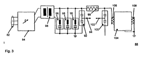
- Fig. 3 shows an electrical schematic diagram 80 of the test circuit, a resonant circuit, to which a part of the test components for tests with particularly high voltages is interconnectable.
- a resonant circuit is single-phase, ie where in Fig. 1 partially 3-phase indicated test components only one phase is used in this arrangement.
- An inverter 84 is connected via its inputs 82 3-phase with a power supply on site, for example, 400V, 50Hz. At the outputs of the inverter 84, which are connected to the terminals of the low voltage side of a second test transformer 96 are connected during operation to a regulated AC voltage. The transformed voltage at the top of the second test transformer 96 is smoothed with the filter elements 86, 88, 90.
- the number of 3 filter elements is shown here only schematically, of course, a higher number of filter elements is conceivable.
- the filter elements are preferably designed for respectively different frequencies, so that by selecting or interconnecting suitable filter elements on the respective boundary conditions of the high-voltage test can be received, of course, existing filter elements may be needed unused.
- a fourth voltage converter 92 is connected, which measures the alternating voltage generated by the inverter 84 and transformed by the second test transformer 96 and fed via a voltage tap 94 of the control device of the inverter 84, not shown.
- the frequency of the AC voltage is controlled so that the resonant circuit is excited in its resonant frequency.
- the resonant circuit mainly comprises a second high voltage choke 98, a device under test 104, and a capacitive fifth voltage divider 100.
- the high-voltage components are matched to one another such that a resonant frequency of about the usual 50Hz mains frequency results, for example, 70Hz - 150Hz, this depends in particular on the characteristics of the test sample to be tested.
- the test object 104 is a 3-phase power transformer whose low-side terminals 108 are each connected to a ground and whose upper-voltage-side terminals 106 are electrically connected in parallel to each other in the resonant circuit.
Landscapes
- Physics & Mathematics (AREA)
- General Physics & Mathematics (AREA)
- Testing Relating To Insulation (AREA)
- Testing Electric Properties And Detecting Electric Faults (AREA)
- Measuring Instrument Details And Bridges, And Automatic Balancing Devices (AREA)
- Rectifiers (AREA)
- X-Ray Techniques (AREA)
Abstract
Description
Die Erfindung betrifft eine Prüfanordnung zur Wechselspannungsprüfung von elektrischen Hochspannungskomponenten mit wenigstens einem Wechselrichter, mit wenigstens einem Prüftransformator, mit wenigstens einer Hochspannungsdrossel und mit wenigstens einer weiteren Hochspannungskomponente als Prüfkomponenten, wobei wenigstens die genannten Prüfkomponenten in einem gemeinsamen quaderförmigen Behälter angeordnet sind.The invention relates to a test arrangement for AC testing of electrical high voltage components with at least one inverter, with at least one test transformer, with at least one high voltage choke and with at least one other high voltage component as test components, wherein at least said test components are arranged in a common cuboid container.
Es ist allgemein bekannt, dass Hochspannungskomponenten, wie beispielsweise Leistungstransformatoren, einem Alterungsprozess unterworfen sind, welcher insbesondere die elektrische Isolation betrifft. Von daher sind zur Sicherstellung eines fehlerfreien Betriebes eines elektrischen Energieverteilungsnetzes mit derartigen Komponenten in bestimmten Zeitintervallen Prüfungen, insbesondere der Leistungstransformatoren, sinnvoll. Eine derartige Prüfung ist auch nach einer Reparatur oder Wartung eines Transformators sinnvoll bzw. erforderlich. Derartige Prüfungen geben Aufschluss über den Zustand beispielsweise der Isolation und ermöglichen auch die Detektion anderer Fehler der betreffenden Komponente.It is well known that high-voltage components, such as power transformers, are subject to an aging process, which relates in particular to electrical insulation. Therefore, to ensure a fault-free operation of an electrical power distribution network with such components in certain time intervals tests, especially the power transformers, makes sense. Such a test is useful or necessary even after a repair or maintenance of a transformer. Such tests provide information about the condition, for example, of the insulation and also enable the detection of other errors of the relevant component.
Komponenten wie Leistungstransformatoren weisen ein sehr hohes Gewicht auf, je nach elektrischer Nennleistung auch über 100t. Ein Transport eines derartigen innerhalb eines elektrischen Energieverteilungsnetzes eingebauten Leistungstransformators in ein fest installiertes Prüffeld, in welchem dieser mittels einer Wechselspannungsprüfung geprüft werden könnte, ist aufgrund des hohen Transportaufwandes für den jeweiligen Leistungstransformator zumeist nicht sinnvoll. Zudem ist in den seltensten Fällen genügend Redundanz in einem Energieverteilungsnetz vorhanden, dass ein Leistungstransformator längerfristig ohne Beeinträchtigung des Netzbetriebes ausgebaut werden könnte.Components such as power transformers have a very high weight, depending on the electrical rating also over 100t. A transport of such installed within an electrical power distribution network power transformer in a permanently installed test field, in which this could be checked by means of an AC test, is usually not useful due to the high transport costs for the respective power transformer. In addition, in the rarest of cases, there is sufficient redundancy in an energy distribution network that a power transformer could be extended in the longer term without affecting network operation.
Aus diesem Grund erfolgen derartige Wechselspannungsprüfungen von Leistungstransformatoren zumeist vor Ort. Die Prüfanordnung mit Wechselspannungsgenerator sowie weiteren für die Prüfung benötigten Hochspannungskomponenten wie Hochspannungsdrossel, Spannungsteiler, Messvorrichtungen aber auch mit Niederspannungskomponenten wie Auswertevorrichtungen wird in mehreren Baugruppen zu dem Ort, an dem sich der zu prüfende Leistungstransformator befindet, transportiert und dort zu einer Prüfanordnung montiert. Insbesondere die Hochspannungsdrossel, welche für eine Resonanzprüfung zur Bildung eines Resonanzschwingkreises mit dem Prüfling benötigt wird, kann mit einer Höhe von beispielsweise 2,5m und einem Innendurchmesser von beispielsweise 1m eine Prüfkomponente von beachtlicher Größe darstellen. Auch der Spannungsteiler, welcher zur Messung der hohen Spannungen von beispielsweise bis zu mehreren 100kV im Resonanzschwingkreis benötigt wird, ist eine Hochspannungskomponente mit ähnlicher Höhe.For this reason, such AC tests of power transformers usually done on site. The test arrangement with alternating voltage generator and other required for the test high-voltage components such as high-voltage inductor, voltage dividers, measuring devices but also with low-voltage components such as evaluation devices is transported in several modules to the place where the power transformer to be tested, and mounted there to form a test arrangement. In particular, the high-voltage choke, which is required for a resonance test to form a resonant circuit with the test specimen, can represent a test component of considerable size with a height of, for example, 2.5 m and an inner diameter of, for example, 1 m. Also, the voltage divider, which is needed to measure the high voltages of, for example, up to several 100kV in the resonant circuit, is a high voltage component of similar magnitude.
Bei der Durchführung einer Wechselspannungsprüfung ist darauf zu achten, dass die Hochspannungskomponenten der Prüfanordnung aufgrund der hohen auftretenden Spannungen einen genügend großen Abstand zueinander und zu angrenzendem Erdpotential aufweisen.When carrying out an AC voltage test, it must be ensured that the high-voltage components of the test arrangement have a sufficiently large distance from each other and to adjacent ground potential due to the high voltages that occur.
So ist aus der Veröffentlichung "A mobile transformer test system based on a static frequency converter" (
Nachteilig ist, dass die Montage der verschiedenen Baugruppen vor Ort mit einem erheblichen Zeitaufwand verbunden ist. Insbesondere die Positionierung und Montage einer Hochspannungsdrossel oder eines Spannungsteilers sind sehr zeitaufwändig.The disadvantage is that the assembly of the various modules on site is associated with a considerable amount of time. In particular, the positioning and mounting of a high-voltage choke or a voltage divider are very time-consuming.
Ausgehend von diesem Stand der Technik ist es Aufgabe der Erfindung, eine Prüfanordnung anzugeben, welche einen verringerten Platzbedarf aufweist und einfach transportierbar ist.Based on this prior art, it is an object of the invention to provide a test arrangement, which has a reduced footprint and is easy to transport.
Diese Aufgabe wird gelöst durch eine Prüfanordnung mit den im Anspruch 1 angegebenen Merkmalen. Diese ist unter anderem dadurch gekennzeichnet, dass die wenigstens eine Hochspannungsdrossel mittels einer Bewegungsvorrichtung durch wenigstens eine Öffnung an einer Begrenzungsfläche des Behälters zumindest teilweise aus diesem bewegbar ist und dass die wenigstens eine weitere Hochspannungskomponente innerhalb des quaderförmigen Behälters von einer Transportposition in eine Arbeitsposition bewegbar ist.This object is achieved by a test arrangement having the features specified in claim 1. This is inter alia characterized in that the at least one high-voltage choke is at least partially movable out of it by means of a movement device through at least one opening on a boundary surface of the container and that the at least one further high-voltage component within the cuboid container can be moved from a transport position into a working position.
Unter Hochspannungskomponenten sind diejenigen elektrischen Komponenten zu verstehen, welch in der Prüfanordnung elektrisch miteinander verschaltbar sind. Dies sind beispielsweise Elemente eines Resonanzschwingkreises wie Induktivität, Kapazität oder Widerstand, aber auch jegliche Messvorrichtungen wie Strom- und Spannungswandlern oder auch Spannungsableiter, welche gegebenenfalls zu Schutzzwecken notwendig sind. Erfindungsgemäß ist die Prüfanordnung nicht zwangsläufig nur als einphasiger Resonanzschwingkreis verschaltbar sondern auch als dreiphasiger Prüfkreis zur phasenweisen Prüfung eines Prüflings wie einem Leistungstransformator, dies allerdings nicht als Resonanzschwingkreise und daher mit einer geringeren Spannung, beispielsweise 110kV. In diesem Fall wären die Hochspannungsprüfkomponenten jeweils dreifach vorzuhalten, insbesondere auch der Wechselrichter, der Prüftransformator, welcher die vom Wechselrichter erzeugte Spannung auf ein höheres Spannungsniveau überträgt, und die Spannungswandler.High-voltage components are to be understood as meaning those electrical components which can be electrically interconnected in the test arrangement. These are, for example, elements of a resonant circuit such as inductance, capacitance or resistance, but also any measuring devices such as current and voltage transformers or voltage arresters, which may be necessary for protection purposes. According to the test arrangement is not necessarily interconnected only as a single-phase resonant circuit but also as a three-phase test circuit for phased testing of a test specimen as a power transformer, but not as resonant circuits and therefore with a lower voltage, for example, 110kV. In this case, the Hochspannungsprüfkomponenten should be kept in each case three times, in particular the inverter, the test transformer, which transmits the voltage generated by the inverter to a higher voltage level, and the voltage converter.
Die Isolationsabstände zwischen der Hochspannungsdrossel und weiteren angrenzenden Hochspannungskomponenten beziehungsweise angrenzendem Erdpotential sind durch die Bewegung der wenigstens einen weiteren Hochspannungskomponente von einer Transportposition in eine Arbeitsposition vorteilhaft steigerbar. Somit ist bei einer ersten Anordnungsvariante, einer Transportposition, der Hochspannungsdrossel innerhalb des Behälters eine besonders platzsparende Anordnung gegeben, welche den Transport der Prüfanordnung vereinfacht. Bei einer weiteren Anordnungsvariante der Hochspannungsdrossel außerhalb des Behälters, in einer Arbeitsposition, sind die Isolationsabstände erhöht, was den Betrieb der Anordnung ermöglicht oder zumindest isolationstechnisch sicherer gestaltet. Der Wechsel zwischen den Anordnungsvarianten erfolgt durch die Bewegungsvorrichtung, beispielsweise einer teleskopähnlichen Schiene, in besonders einfacher Form.The insulation distances between the high-voltage choke and other adjacent high-voltage components or adjacent ground potential can advantageously be increased by moving the at least one further high-voltage component from a transport position to a working position. Thus, in a first arrangement variant, a transport position, the high-voltage throttle within the container is given a particularly space-saving arrangement, which simplifies the transport of the test arrangement. In a further arrangement variant of the high-voltage choke outside the container, in a working position, the insulation distances are increased, which allows the operation of the arrangement or at least made more secure isolation technology. The change between the arrangement variants takes place by the movement device, for example a telescope-like rail, in a particularly simple form.
Nach Herausbewegen der Hochspannungsdrossel aus dem Behälter ist ein Freiraum innerhalb des Behälters entstanden. Dieser wird erfindungsgemäß durch eine Neuanordnung ausgewählter weiterer elektrischer Hochspannungskomponenten der Prüfanordnung genutzt. Auf diese Weise sind die Prüfkomponenten während des Transportes der Prüfanordnung kompakt und ohne Berücksichtigung von Isolationsabständen innerhalb des quaderförmigen Behälters in der Transportposition anordenbar. Beim Aufbau des Prüfsystems vor Ort wird zunächst die Drossel aus dem Behälter bewegt. Danach wird der so entstandene Freiraum durch eine isolationsgerechte Anordnung von weiteren Hochspannungskomponenten genutzt, welche durch deren jeweilige Arbeitsposition bestimmt ist.After moving out of the high-voltage throttle from the container, a free space has formed within the container. This is used according to the invention by a rearrangement of selected further electrical high-voltage components of the test arrangement. In this way, the test components during transport of the test arrangement are compact and can be arranged without consideration of insulation distances within the cuboid container in the transport position. When setting up the test system on site, the throttle is first moved out of the container. Thereafter, the resulting space is used by an isolation-oriented arrangement of other high-voltage components, which is determined by their respective operating position.
Es ist von Fall zu Fall selbstverständlich auch denkbar, dass der durch die herausbewegte Drossel freigewordene Raum nicht notwendigerweise durch eine Neuanordnung der weiteren Hochspannungskomponenten genutzt wird, sondern dass die weiteren Komponenten in Transportposition einen Freiraum im Inneren des Containers ermöglichen, welcher dann als Stauraum beispielsweise für ebenfalls benötigte Kleinkomponenten genutzt wird. Bei Aufbau der Prüfanordnung werden die Kleinkomponenten aus dem Stauraum entfernt und es erfolgt die isolationsgerechte Anordnung der weiteren Hochspannungskomponenten.Of course, it is also conceivable on a case-by-case basis that the space released by the moved-out throttle is not necessarily used by a rearrangement of the further high-voltage components, but that the further components in transport position allow a free space in the interior of the container, which then serves as storage space for example also needed small components is used. When building the test arrangement, the small components are removed from the storage space and there is the isolation-oriented arrangement of the other high-voltage components.
In vorteilhafter Weise wird durch die kompakte Anordnung der Drossel und der weiteren Hochspannungskomponenten innerhalb des Behälters ein Transport des Behälters bzw. der Prüfanordnung vereinfacht.Advantageously, a transport of the container or the test arrangement is simplified by the compact arrangement of the throttle and the other high-voltage components within the container.
In bevorzugter Weise ist die wenigstens eine weitere Hochspannungskomponente ein elektrisches Filterelement. Derartige Filterelemente werden benötigt, um die von dem Wechselrichter erzeugte Wechselspannung zu glätten, d.h. den Anteil der ungewollten Oberschwingungen zu reduzieren, welche beispielsweise eine Teilentladungs- (TE-) Messung beeinflussen würden. Ein Filterelement weist in der Regel eine Induktivität und eine Kapazität auf, es sind jedoch auch Filterelementmodule mit nur einer Kapazität oder Induktivität denkbar. Es sind auch mehrere Filterelemente und/oder Filterelementmodule zu einem Filter verschaltbar. Bei derartigen Filterelementen ist ebenfalls auf einen hinreichenden Isolationsabstand zu anderen Hochspannungskomponenten zu achten.Preferably, the at least one further high-voltage component is an electrical filter element. Such filter elements are needed to smooth the AC voltage generated by the inverter, i. reduce the proportion of unwanted harmonics that would affect, for example, a partial discharge (TE) measurement. As a rule, a filter element has an inductance and a capacitance, but filter element modules with only one capacitance or inductance are also conceivable. There are also several filter elements and / or filter element modules can be connected to a filter. In such filter elements is also important to ensure a sufficient isolation distance to other high voltage components.
In einer weiteren Variante der Prüfanordnung ist die wenigstens eine weitere Hochspannungskomponente ein Spannungswandler. Auch dieser ist eine Hochspannungskomponente, welche im Betrieb einen erhöhten Isolationsabstand benötigt.In a further variant of the test arrangement, the at least one further high-voltage component is a voltage converter. This is also a high-voltage component, which requires an increased isolation distance during operation.
In einer bevorzugten Ausgestaltungsvariante der erfindungsgemäßen Prüfanordnung ist die wenigstens eine weitere Hochspannungskomponente mittels einer Führungsvorrichtung bewegbar. Ein Bewegungsvorgang von der Transportposition in die Arbeitsposition ist hierdurch besonders vereinfacht.In a preferred embodiment variant of the test arrangement according to the invention, the at least one further high-voltage component can be moved by means of a guide device. A movement process from the transport position to the working position is thereby particularly simplified.
In einer besonders bevorzugten Variante der Erfindung ist die wenigstens eine weitere Hochspannungskomponente längs einer Führungsschiene bewegbar. Dies ermöglicht ebenso wie die erfindungsgemäße Bewegung der wenigstens einen weiteren Hochspannungskomponente mittels einer Schwenkvorrichtung ein positionsgenaues und zugleich sicheres Bewegen zwischen Transport- und Arbeitsposition.In a particularly preferred variant of the invention, the at least one further high-voltage component is movable along a guide rail. This allows as well as the inventive movement of the at least one further high-voltage component by means of a pivoting device a positionally accurate and at the same time safe movement between transport and working position.
Entsprechend einer weiteren Umsetzungsvariante der erfindungsgemäßen Prüfanordnung ist die wenigstens eine weitere Hochspannungskomponente in der Transport- und/oder Arbeitsposition arretierbar. Dies erhöht die Sicherheit beim Transport und gewährleistet im Prüfbetrieb eine korrekte und betriebssichere Positionierung der Prüfkomponenten. Eine derartige Arretierung ist beispielsweise mittels einer schraubbaren Klemmverbindung oder einem Arretiermechanismus mit Schnappvorrichtung realisierbar.According to a further implementation variant of the test arrangement according to the invention, the at least one further high-voltage component in the transport and / or working position can be locked. This increases safety during transport and ensures correct and reliable positioning of the test components in test mode. Such a lock can be realized, for example, by means of a screwable clamping connection or a locking mechanism with snap device.
Entsprechend einer weiteren Umsetzungsvariante der erfindungsgemäßen Prüfanordnung ist die wenigstens eine weitere Hochspannungskomponente im oberen Bereich des quaderförmigen Behälters angebracht und führbar, beispielsweise von der Decke hängend. Dies ermöglicht insbesondere, den Raum auf dem Boden des Behälters während des Transportes als Stauraum für benötigte Kleinteile vorzusehen, oder aber auch, auf dem Boden des Behälters weitere Hochspannungskomponenten stehend anzuordnen. Der im Behälter zur Verfügung stehende Platz wird hiermit in hohem Maße genutzt.According to a further implementation variant of the test arrangement according to the invention, the at least one further high-voltage component in the upper region of the cuboid container is mounted and feasible, for example hanging from the ceiling. This makes it possible in particular to provide the space on the bottom of the container during transport as storage space for small parts needed, or else to arrange further high-voltage components standing on the bottom of the container. The available space in the container is hereby used to a great extent.
Entsprechend vorteilhaft ist es auch, die elektrischen Verbindungsleitungen zur wenigstens einen weiteren Hochspannungskomponente im oberen Bereich des quaderförmigen Behälters anzubringen. Diese Leitungen sind vorzugsweise so zu bemessen, dass die mit diesen verbundenen weiteren Hochspannungskomponenten sowohl in Transport- als auch in Arbeitsposition von den Leitungen ohne einen zusätzlichen Verbindungsvorgang erreicht sind. Dies ist beispielsweise mit einer Schlaufenführung einer flexiblen Leitung erreichbar. Durch das Führen der Leitungen im Deckenbereich ist zudem das Unfallrisiko für Bedienpersonal, welches sich beim Aufbau der Prüfanordnung vor Ort auf dem Behälterboden bewegt, reduziert.It is also correspondingly advantageous to attach the electrical connecting lines to the at least one further high-voltage component in the upper region of the parallelepipedic container. These lines are preferably to be dimensioned so that the other high voltage components connected to these are achieved in the transport as well as in working position of the lines without an additional connection operation. This is for example with a loop guide a flexible line accessible. By guiding the cables in the ceiling area, moreover, the risk of accidents for operating personnel, which moves on site during installation of the test arrangement on the container floor, is reduced.
Vorteilhafterweise sind die Verbindungsleitungen Kabel, welche von einer Isolationsschicht ummantelt sind. Bei der Anordnung von derart isolierten Kabeln innerhalb des quaderförmigen Behälters ist auf Isolationsabstände der Kabel zu geerdeten Gegenständen weitestgehend nicht zu achten, was die Anordnung weiter vereinfacht.Advantageously, the connecting lines are cables which are encased by an insulating layer. In the arrangement of such insulated cables within the parallelepiped container is to be largely disregarded isolation distances of the cable to grounded objects, which further simplifies the arrangement.
In einer bevorzugten Ausprägung der Prüfanordnung weist die Führungsvorrichtung für die wenigstens eine weitere Hochspannungskomponente einen Antrieb auf, beispielsweise einen Spindelantrieb mit Elektromotor oder einen hydraulischen Antrieb. Das Verfahren von der Transportposition in die Arbeitsposition und zurück wird dadurch weiter vereinfacht.In a preferred embodiment of the test arrangement, the guide device for the at least one further high-voltage component has a drive, for example a spindle drive with electric motor or a hydraulic drive. The process from the transport position to the working position and back is thereby further simplified.
Der zur Verfügung stehende Platz im Behälter wird erfindungsgemäß besonders gut ausgenutzt, wenn sich die Arbeitsposition der wenigstens einen weiteren Hochspannungskomponente zumindest teilweise mit einem Bereich der nicht herausbewegten Drossel überschneidet.The available space in the container is particularly well utilized according to the invention when the working position of the at least one further high-voltage component overlaps at least partially with a region of the throttle which has not moved out.
In einer Ausgestaltungsform der Prüfanordnung ist ein Spannungsteiler zusammen mit der Hochspannungsdrossel aus dem quaderförmigen Behälter bewegbar. Durch das Herausbewegen auch eines Spannungsteilers aus dem Innenbereich des quaderförmigen Behälters wird in der Arbeitsposition noch mehr Platz im Behälter geschaffen, so dass die noch im Behälter verbleibenden Prüfkomponenten in einen nochmals erhöhten Isolationsabstand zueinander bewegbar sind.In one embodiment of the test arrangement, a voltage divider is movable together with the high-voltage throttle from the cuboid container. By moving out even a voltage divider from the inner region of the cuboid container even more space in the container is created in the working position, so that the remaining in the container test components are moved toward each other in a further increased isolation distance.
Um einen sicheren Isolationsabstand zwischen der herausbewegten Hochspannungsdrossel und dem mit ihr herausbewegten Spannungsteiler herzustellen, ist erfindungsgemäß vorgesehen, den Spannungsteiler bei ausgefahrener Hochspannungsdrossel mit einer weiteren Bewegungsvorrichtung von der Hochspannungsdrossel weg in eine Isolationsposition zu bewegen. Vorzugsweise sind die Hochspannungsdrossel und der Spannungsteiler hierbei stets längs paralleler Achsen ausgerichtet.In order to produce a safe isolation distance between the high-voltage choke moved out and the voltage divider moved out with it, it is provided according to the invention to move the voltage divider away from the high-voltage choke into an isolation position when the high-voltage choke is extended. Preferably, the high voltage choke and the voltage divider always aligned along parallel axes.
Besonders bevorzugt ist in diesem Zusammenhang die Ausgestaltung des Behälters als Container mit Standardabmessung, beispielsweise als Container mit 40 Fuß Länge. Dieser ist in einer weiteren Variante gemäß CSC (Container Safety Convention) zugelassen und somit in jeder beliebigen Position innerhalb eines Containerstapels auf einem Containerschiff platzierbar. Hierdurch wird die Transportierbarkeit der Prüfanordnung noch weiter erhöht.Particularly preferred in this context is the design of the container as a container of standard size, for example as a container with 40 feet in length. This is approved in another variant according to CSC (Container Safety Convention) and thus placed in any position within a container stack on a container ship. As a result, the portability of the test arrangement is further increased.
Vorteilhafterweise ist die wenigstens eine Öffnung des Behälters verschließbar. Bei einem Transport des Behälters mit geschlossenen Öffnungen sind die in ihm befindlichen Hochspannungskomponenten der Prüfanordnung somit besser geschützt.Advantageously, the at least one opening of the container is closable. When the container is transported with closed openings, the high-voltage components of the test arrangement located in it are thus better protected.
Weitere vorteilhafte Ausgestaltungsmöglichkeiten sind den weiteren abhängigen Ansprüchen zu entnehmen.Further advantageous embodiment possibilities can be found in the further dependent claims.
Anhand der in den Zeichnungen dargestellten Ausführungsbeispiele sollen die Erfindung, weitere Ausführungsformen und weitere Vorteile näher beschrieben werden.Reference to the embodiments illustrated in the drawings, the invention, further embodiments and other advantages will be described in detail.
Es zeigen:
- Fig. 1
- eine exemplarische Prüfanordnung in einer Seitenansicht,
- Fig. 2
- eine exemplarische Prüfanordnung in einer Draufsicht und
- Fig. 3
- eine exemplarische Prüfschaltung
- Fig. 1
- an exemplary test arrangement in a side view,
- Fig. 2
- an exemplary test arrangement in a plan view and
- Fig. 3
- an exemplary test circuit
Eine erste Hochspannungsdrossel, welche auf einer Bewegungsvorrichtung 44 angeordnet ist, ist im oberen Bildteil in eingefahrenem Zustand in einer Transportposition 16 innerhalb der Begrenzungen des Containers 12 gezeigt. Von der Decke des Containers 12 hängend und an einer jeweiligen Führungsvorrichtung 20a, 20b und 20c montiert sind drei Filterelemente 18a, 18b und 18c in Transportposition angedeutet. Die Führungsvorrichtungen 20a, 20b und 20c sind in diesem Fall jeweils Hohlschienen, längs derer die jeweiligen Filterelemente über eine hakenähnliche Vorrichtung bewegbar sind, wobei in dieser Darstellung lediglich die erste Führungsvorrichtung 20a gezeigt ist, während die anderen beiden 20b und 20c verdeckt sind. Mittels einer nicht gezeigten Arretiervorrichtung sind die Filterelemente 18a, 18b und 18c zumindest in der oben gezeigten Transport- und in der unten gezeigten Arbeitsposition arretierbar. Der elektrische Anschluss der Filterelemente 18a, 18b und 18c erfolgt über nicht gezeigte isolierte Kabel von der Decke des Containers 12.A first high-voltage throttle, which is arranged on a
Es ist sowohl denkbar, dass die Filterelemente 18a, 18b und 18c permanent in beiden Positionen mit den jeweiligen Kabeln verbunden sind, es ist aber ebenso denkbar, dass die Kabelverbindung steckbar ist. Dies ist insbesondere dann von Vorteil, wenn die die Prüfanordnung an die örtlichen Gegebenheiten, die Frequenz der erzeugten Wechselspannung bzw. den Prüfling angepasst wird. Je nach Konstellation können auch nur ausgewählte Filterelemente, welche beispielsweise jeweils auf eine bestimmte Filterfrequenz angepasst sind, verschaltet werden.It is also conceivable that the
Auf dem Boden des Containers 12 angedeutet sind drei Spannungswandler 22a, 22b, 22c in Transportposition, wobei hier aufgrund der Seitenansicht lediglich der erste Spannungswandler 22a sichtbar ist. Durch die vertikal gegenüberliegende Anordnung der von der Decke hängenden Filterelemente 18a, 18b und 18c sowie der auf dem Containerboden stehenden Spannungswandler 22a, 22b und 22c ist in der Transportposition der Prüfkomponenten der zur Verfügung stehende Innenraum des Containers 12 in hohem Maße ausgenutzt.Indicated on the bottom of the
Im unteren Teil der
Schematisch abgegrenzt zum bisher beschriebenen hinteren Bereich des Containers 12 ist der vordere Bereich des Containers 12 mit der Grenzlinie 30. Der vordere Bereich enthält weitere Komponenten wie beispielsweise Wechselrichter oder aber auch einen Arbeitsraum mit Mess- und Auswertevorrichtungen. Diese Komponenten sind aber in diesem Beispiel als gegenüber dem Container 12 unbeweglich anzunehmen, weshalb ihnen im Rahmen dieser Erfindung eine untergeordnete Bedeutung zukommt.Schematically delimited from the previously described rear region of the
Eine weitere nunmehr sichtbare Komponente ist die Führungsvorrichtung 52 für den zweiten Spannungswandler, welcher in der oberen Darstellung in Transportposition 22b und in der unteren Darstellung in einer Arbeitsposition 40 dargestellt ist. Die Führungsvorrichtung ist in diesem Fall eine in den Boden des Containers eingelassene Führungsschiene, welche über einen Antrieb mittels Elektromotor und Kette verfügt. Die benachbarten Spannungswandler 22a und 22c sind fest montiert, verfügen also über keinerlei Führungsvorrichtungen.Another now visible component is the
In der
Selbstverständlich ist es möglich, die Führungsvorrichtungen 20a, 20b und 20c - abweichend zur Darstellung in
Ein Wechselrichter 84 ist über seine Eingänge 82 3-phasig mit einer Spannungsversorgung vor Ort verbunden, beispielsweise 400V, 50Hz. An den Ausgängen des Wechselrichters 84, welche mit den Anschlüssen der Unterspannungsseite eines zweiten Prüftransformators 96 verbunden sind, liegt während des Betriebes eine geregelte Wechselspannung an. Die transformierte Spannung an der Oberseite des zweiten Prüftransformators 96 wird mit den Filterelementen 86, 88, 90 geglättet. Die Anzahl von 3 Filterelementen ist hier nur schematisch dargestellt, selbstverständlich ist auch eine höhere Anzahl von Filterelementen denkbar. Die Filterelemente sind vorzugsweise für jeweils verschiedene Frequenzen ausgelegt, so dass durch Auswahl bzw. Verschaltung geeigneter Filterelemente auf die jeweiligen Randbedingungen der Hochspannungsprüfung eingegangen werden kann, wobei selbstverständlich vorhandene Filterelemente bedarfsweise ungenutzt sein können. Elektrisch parallel zu den Filterelementen 86, 88, 90 ist ein vierter Spannungswandler 92 geschaltet, welcher die vom Wechselrichter 84 erzeugte und vom zweiten Prüftransformators 96 transformierte Wechselspannung misst und über einen Spannungsabgriff 94 der nicht dargestellten Regelvorrichtung des Wechselrichters 84 zuführt.An
Die Frequenz der Wechselspannung ist derart geregelt, dass der Resonanzschwingkreis in seiner Resonanzfrequenz angeregt wird. Der Resonanzschwingkreis weist in der Hauptsache eine zweite Hochspannungsdrossel 98, einen Prüfling 104 und einen kapazitiven fünften Spannungsteiler 100 auf. Die Hochspannungskomponenten sind derart aufeinander abgestimmt, dass sich eine Resonanzfrequenz von etwas über den üblichen 50Hz Netzfrequenz ergibt, beispielsweise 70Hz - 150Hz, wobei diese insbesondere von den Kenndaten des zu testenden Prüflings abhängt. Der Prüfling 104 ist in der dargestellten Fig. ein 3-phasiger Leistungstransformator, dessen unterspannungsseitigen Anschlüsse 108 jeweils mit einer Erdung verbunden sind und dessen oberspannungsseitigen Anschlüsse 106 elektrisch parallel zueinander im Schwingkreis verschaltet sind.The frequency of the AC voltage is controlled so that the resonant circuit is excited in its resonant frequency. The resonant circuit mainly comprises a second
- 1010
- exemplarische Prüfanordnung in Seitenansichtexemplary test arrangement in side view
- 1212
- quaderförmiger Behältercuboid container
- 1414
- erster Prüftransformatorfirst test transformer
- 1616
- erste Hochspannungsdrossel in erster Positionfirst high-voltage choke in the first position
- 18a18a
- erstes Filterelement in Transportpositionfirst filter element in transport position
- 18b18b
- zweites Filterelement in Transportpositionsecond filter element in transport position
- 18c18c
- drittes Filterelement in Transportpositionthird filter element in transport position
- 20a20a
- Führungsvorrichtung für erstes FilterelementGuiding device for first filter element
- 20b20b
- Führungsvorrichtung für zweites FilterelementGuide device for second filter element
- 20c20c
- Führungsvorrichtung für drittes FilterelementGuide device for third filter element
- 22a22a
- erster Spannungswandlerfirst voltage converter
- 22b22b
- zweiter Spannungswandler in Transportpositionsecond voltage converter in transport position
- 22c22c
- dritter Spannungswandler (verdeckt)third voltage converter (hidden)
- 2424
- LKW-AufliegerTruck trailers
- 2525
- Räderbikes
- 2828
- LKWtruck
- 3030
- Grenzlinieboundary line
- 32a32a
- erstes Filterelement in Arbeitspositionfirst filter element in working position
- 32b32b
- zweites Filterelement in Arbeitspositionsecond filter element in working position
- 32c32c
- drittes Filterelement in Arbeitspositionthird filter element in working position
- 34a34a
- Bewegungsrichtung des ersten FilterelementesDirection of movement of the first filter element
- 34b34b
- Bewegungsrichtung des zweiten FilterelementesMovement direction of the second filter element
- 34c34c
- Bewegungsrichtung des dritten FilterelementesMovement direction of the third filter element
- 3636
- erste Hochspannungsdrossel in zweiter Positionfirst high-voltage choke in second position
- 3838
- Bewegungsrichtung der ersten HochspannungsdrosselDirection of movement of the first high-voltage choke
- 4040
- zweiter Spannungswandler in Arbeitspositionsecond voltage converter in working position
- 4242
- Bewegungsrichtung des zweiten SpannungswandlersDirection of movement of the second voltage converter
- 4444
- Bewegungsvorrichtung für erste HochspannungsdrosselMovement device for first high-voltage throttle
- 5050
- exemplarische Prüfanordnung in Draufsichtexemplary test arrangement in plan view
- 5252
- Führungsvorrichtung für zweiten SpannungswandlerGuide device for second voltage converter
- 5454
- ausfahrbare Abstützungextendable support
- 8080
- exemplarische Prüfschaltungexemplary test circuit
- 8282
- 3-phasige Anschlussleitung3-phase connection cable
- 8484
- Wechselrichterinverter
- 8686
- viertes Filterelementfourth filter element
- 8888
- fünftes Filterelementfifth filter element
- 9090
- sechstes Filterelementsixth filter element
- 9292
- vierter Spannungswandlerfourth voltage converter
- 9494
- Spannungsabgriff von viertem SpannungswandlerVoltage tap of fourth voltage transformer
- 9696
- zweiter Prüftransformatorsecond test transformer
- 9898
- zweite Hochspannungsdrosselsecond high voltage choke
- 100100
- fünfter Spannungswandlerfifth voltage converter
- 102102
- Spannungsabgriff von fünftem SpannungswandlerVoltage tap of fifth voltage transformer
- 104104
- Prüflingexaminee
- 106106
- parallel geschaltete Eingänge des Prüflingsparallel inputs of the test object
- 108108
- parallel geschaltete Ausgänge des Prüflingsparallel outputs of the device under test
Claims (15)
- Test arrangement (10, 50) for AC voltage testing of electrical high-voltage components (104) comprising• at least one inverter (84), at least one test transformer (14, 96), at least one high-voltage inductor (16, 36, 98) and at least one further high-voltage component (18a, 18b, 18c, 22a, 22b, 22c, 86, 88, 90, 92) as test components,• a common cuboid container (12) in which at least said test components are arranged,• a movement apparatus (44),• a guide apparatus (20a, 20b, 20c, 52),characterized in that the at least one high-voltage inductor (16, 36, 98) can be moved at least partially out of the container (12), through at least one opening on a boundary surface of the container (12), by means of the movement apparatus (44), and in this way a change is made possible between a first arrangement variant of the high-voltage inductor within the cuboid container (12) and a second arrangement variant with an adequate isolation separation for carrying out the AC voltage test, and in that the at least one further high-voltage component (18a, 18b, 18c, 22a, 22b, 22c, 86, 88, 90, 92) can be moved within the cuboid container (12) by means of the guide apparatus (20a, 20b, 20c, 52) from a transport position (18a, 18b, 18c, 22b) to a working position (32a, 32b, 32c, 64).
- Test arrangement according to Claim 1, characterized in that the at least one further high-voltage component (18a, 18b, 18c, 22a, 22b, 22c, 86, 88, 90, 92) is an electrical filter element (18a, 18b, 18c, 86, 88, 90).
- Test arrangement according to Claim 1 or 2, characterized in that the at least one further high-voltage component (18a, 18b, 18c, 22a, 22b, 22c, 86, 88, 90, 92) is a voltage transformer (22a, 22b, 22c, 92).
- Test arrangement according to one of the preceding claims, characterized in that the guide apparatus (20a, 20b, 20c, 52) comprises a guide rail along which the at least one further high-voltage component (18a, 18b, 18c, 22a, 22b, 22c, 86, 88, 90, 92) can be moved.
- Test arrangement according to one of the preceding claims, characterized in that the at least one further high-voltage component (18a, 18b, 18c, 22a, 22b, 22c, 86, 88, 90, 92) can be pivoted about a rotation axis.
- Test arrangement according to one of the preceding claims, characterized in that the at least one further high-voltage component (18a, 18b, 18c, 22a, 22b, 22c, 86, 88, 90, 92) can be locked in the transport position (18a, 18b, 18c, 22b) and/or in the working position (32a, 32b, 32c, 64).
- Test arrangement according to one of the preceding claims, characterized in that the at least one further high-voltage component (18a, 18b, 18c, 22a, 22b, 22c, 86, 88, 90, 92) is fitted and can be guided in the upper area of the cuboid container (12).
- Test arrangement according to one of the preceding claims, characterized in that electrical connecting lines to the at least one further high-voltage component (18a, 18b, 18c, 22a, 22b, 22c, 86, 88, 90, 92) are fitted in the upper area of the cuboid container (12).
- Test arrangement according to Claim 8, characterized in that the connecting lines are cables, which are sheathed by an insulation layer.
- Test arrangement according to one of the preceding claims, characterized in that the guide apparatus (20a, 20b, 20c, 52) for the at least one further high-voltage component (18a, 18b, 18c, 22a, 22b, 22c, 86, 88, 90, 92) has a drive.
- Test arrangement according to one of the preceding claims, characterized in that the working position (32a, 32b, 32c, 64) of the at least one further high-voltage component (18a, 18b, 18c, 22a, 22b, 22c, 86, 88, 90, 92) at least partially intersects an area of the inductor (16) which has not been moved out.
- Test arrangement according to one of the preceding claims, characterized in that a voltage divider (100) can be moved, together with the high-voltage inductor (16, 36, 98), out of the cuboid container (12).
- Test arrangement according to Claim 12, characterized in that the voltage divider (100) can be moved relative to the high-voltage inductor (16, 36, 98) by means of a further movement apparatus.
- Test arrangement according to one of the preceding claims, characterized in that the cuboid container (12) is a transportable freight container with standard dimensions.
- Test arrangement according to one of the preceding claims, characterized in that the at least one opening can be closed.
Priority Applications (1)
| Application Number | Priority Date | Filing Date | Title |
|---|---|---|---|
| EP09761392.1A EP2286254B2 (en) | 2008-06-12 | 2009-05-27 | Test assembly for ac testing of electric high voltage components |
Applications Claiming Priority (3)
| Application Number | Priority Date | Filing Date | Title |
|---|---|---|---|
| EP08010691.7A EP2133704B2 (en) | 2008-06-12 | 2008-06-12 | Test assembly for AC testing of electric high voltage components |
| EP09761392.1A EP2286254B2 (en) | 2008-06-12 | 2009-05-27 | Test assembly for ac testing of electric high voltage components |
| PCT/EP2009/003756 WO2009149829A1 (en) | 2008-06-12 | 2009-05-27 | Test arrangement for ac voltage testing of electrical high voltage components |
Publications (3)
| Publication Number | Publication Date |
|---|---|
| EP2286254A1 EP2286254A1 (en) | 2011-02-23 |
| EP2286254B1 true EP2286254B1 (en) | 2011-08-24 |
| EP2286254B2 EP2286254B2 (en) | 2015-12-02 |
Family
ID=39960711
Family Applications (3)
| Application Number | Title | Priority Date | Filing Date |
|---|---|---|---|
| EP08010691.7A Active EP2133704B2 (en) | 2008-06-12 | 2008-06-12 | Test assembly for AC testing of electric high voltage components |
| EP09004940A Revoked EP2133888B1 (en) | 2008-06-12 | 2009-04-03 | Test assembly for AC testing of electric high voltage components |
| EP09761392.1A Active EP2286254B2 (en) | 2008-06-12 | 2009-05-27 | Test assembly for ac testing of electric high voltage components |
Family Applications Before (2)
| Application Number | Title | Priority Date | Filing Date |
|---|---|---|---|
| EP08010691.7A Active EP2133704B2 (en) | 2008-06-12 | 2008-06-12 | Test assembly for AC testing of electric high voltage components |
| EP09004940A Revoked EP2133888B1 (en) | 2008-06-12 | 2009-04-03 | Test assembly for AC testing of electric high voltage components |
Country Status (13)
| Country | Link |
|---|---|
| US (3) | US8427172B2 (en) |
| EP (3) | EP2133704B2 (en) |
| CN (2) | CN102057286B (en) |
| AR (1) | AR072126A1 (en) |
| AT (3) | ATE522817T1 (en) |
| AU (3) | AU2009256991B9 (en) |
| BR (3) | BRPI0915158B1 (en) |
| CA (2) | CA2726427C (en) |
| ES (2) | ES2371787T5 (en) |
| RU (2) | RU2494410C2 (en) |
| SA (1) | SA109300379B1 (en) |
| UA (2) | UA105179C2 (en) |
| WO (3) | WO2009149829A1 (en) |
Families Citing this family (21)
| Publication number | Priority date | Publication date | Assignee | Title |
|---|---|---|---|---|
| DE102007059289B4 (en) * | 2007-12-08 | 2011-07-28 | Maschinenfabrik Reinhausen GmbH, 93059 | Device for testing transformers |
| ES2371787T5 (en) | 2008-06-12 | 2016-02-19 | Abb Technology Ag | Test set for an alternating current test of high voltage electrical components |
| EP2133703B1 (en) | 2008-06-12 | 2011-10-12 | ABB Technology AG | Test assembly for surge voltage testing of high voltage electrical components |
| DE102009023713B4 (en) * | 2009-06-03 | 2014-06-05 | Maschinenfabrik Reinhausen Gmbh | Device for testing high voltage equipment |
| GB2480455B (en) | 2010-05-18 | 2012-10-10 | Megger Instr Ltd | High voltage liquid dielectric test vessel |
| CN102285333B (en) * | 2011-07-13 | 2012-10-03 | 苏州华电电气股份有限公司 | Extra-high voltage power transformer check vehicle |
| ES2460628T3 (en) * | 2011-11-02 | 2014-05-14 | Abb Technology Ag | High voltage transformer module |
| EP2590490B1 (en) * | 2011-11-02 | 2014-01-08 | ABB Technology AG | Test container |
| DE102012101548B4 (en) | 2012-02-27 | 2015-11-19 | Maschinenfabrik Reinhausen Gmbh | Test system and method for induced voltage testing and power loss measurement of high voltage test objects |
| ES2646437T3 (en) * | 2012-06-06 | 2017-12-13 | Prysmian S.P.A. | Bypass system for overhead power lines |
| DE102012105045A1 (en) * | 2012-06-12 | 2013-12-12 | Maschinenfabrik Reinhausen Gmbh | Device for calibrating a power measurement system for power transformers |
| JP6132272B2 (en) * | 2012-07-25 | 2017-05-24 | サン パテント トラスト | COMMUNICATION DEVICE, COMMUNICATION METHOD, AND INTEGRATED CIRCUIT |
| CN102944775B (en) * | 2012-10-30 | 2014-10-22 | 苏州华电电气股份有限公司 | Characteristic test system for high-capacity transformer based on high-voltage variable-frequency power supply |
| ES2563109T3 (en) * | 2012-12-19 | 2016-03-10 | Abb Research Ltd. | Transformer arrangement to mitigate transient voltage oscillations |
| EP2853908B1 (en) | 2013-09-25 | 2021-03-31 | ABB Power Grids Switzerland AG | Test system for high voltage components |
| EP2863236B1 (en) * | 2013-10-18 | 2019-12-04 | ABB Schweiz AG | Test system for high voltage components |
| RU2659588C1 (en) * | 2017-01-30 | 2018-07-03 | Илья Николаевич Джус | Transformer inverter tester |
| FR3074599B1 (en) * | 2017-12-05 | 2019-12-20 | Alstom Transport Technologies | RAIL TRACTION BLOCK TEST SYSTEM |
| RU2739702C1 (en) * | 2019-12-02 | 2020-12-28 | Илья Николаевич Джус | Transformer testing facility |
| US11876384B2 (en) * | 2020-12-15 | 2024-01-16 | Otis Elevator Company | Wireless power transfer device |
| WO2023106961A1 (en) * | 2021-12-08 | 2023-06-15 | Федеральное Государственное Унитарное Предприятие "Российский Федеральный Ядерный Центр - Всероссийский Научно - Исследовательский Институт Технической Физики Имени Академика Е.И. Забабахина" | Mobile high-voltage apparatus for testing power transformers |
Family Cites Families (24)
| Publication number | Priority date | Publication date | Assignee | Title |
|---|---|---|---|---|
| DE521475C (en) * | 1929-03-28 | 1931-03-21 | Koch & Sterzel Akt Ges | Transformer, especially measuring transducer, for high voltages, consisting of individual systems connected in cascade with primary windings and thrust and overcoupling windings in series |
| US2032904A (en) | 1935-10-03 | 1936-03-03 | Westinghouse Electric & Mfg Co | Lightning-stroke generator |
| US2237812A (en) * | 1940-02-23 | 1941-04-08 | Gen Electric | Portable unit substation |
| US2551841A (en) * | 1946-11-27 | 1951-05-08 | Westinghouse Electric Corp | Electrical apparatus |
| DE1563442A1 (en) | 1966-12-08 | 1970-04-02 | Siemens Ag | Short-circuit reactor |
| DE2328375C3 (en) † | 1973-06-04 | 1978-12-14 | Transformatoren Union Ag, 7000 Stuttgart | Capacitor battery for voltage control on the windings of transformers and chokes |
| AT330887B (en) | 1974-11-08 | 1976-07-26 | Leinweber Anstalt Ing Joh | DEVICE FOR PRESSING CURVED BRAKE PADS |
| JPS5936091Y2 (en) * | 1978-11-24 | 1984-10-05 | 株式会社明電舎 | Mobile substation equipment |
| US4427898A (en) † | 1981-12-22 | 1984-01-24 | Mitsubishi Denki Kabushiki Kaisha | Mobile power station apparatus |
| JPS58177915U (en) † | 1982-05-20 | 1983-11-28 | 三菱電機株式会社 | mobile electrical equipment |
| SU1179234A1 (en) | 1983-08-19 | 1985-09-15 | Проектно-конструкторское бюро электрогидравлики АН УССР | Arrangement for excitation of seismic waves |
| JPS61102176A (en) | 1984-10-24 | 1986-05-20 | Kansai Electric Power Co Inc:The | Impulse voltage generator and controller thereof |
| JPH0738011B2 (en) * | 1988-05-16 | 1995-04-26 | 株式会社日立製作所 | Abnormality diagnosis system for high-voltage power equipment |
| US5686697A (en) * | 1995-01-06 | 1997-11-11 | Metatech Corporation | Electrical circuit suspension system |
| RU2083824C1 (en) | 1995-06-13 | 1997-07-10 | Научно-исследовательский институт высоких напряжений при Томском политехническом университете | Rock crushing method |
| DE19639023A1 (en) | 1996-09-23 | 1998-03-26 | Haefely Trench Ag | Pulse voltage generator circuit |
| US6313640B1 (en) * | 1998-02-03 | 2001-11-06 | Abb Power T & D Company, Inc. | System and method for diagnosing and measuring partial discharge |
| DE50015322D1 (en) | 2000-12-20 | 2008-10-02 | Haefely Test Ag | WEARING CHAMBER STRUCTURE FOR ELECTRICAL IMPULSE GENERATOR |
| US6586697B1 (en) * | 2002-07-26 | 2003-07-01 | Pauwels Contracting Inc. | Transportable electrical switching assembly with high voltage circuit interrupter |
| US6586671B1 (en) | 2002-08-06 | 2003-07-01 | Interrail Signal, Inc. | Above ground track signal terminal apparatus |
| CN2574062Y (en) * | 2002-10-17 | 2003-09-17 | 北京安控科技发展有限公司 | Current signal conditioning circuit |
| RU2222858C1 (en) * | 2002-10-31 | 2004-01-27 | Механошин Борис Иосифович | Device for remote monitoring of overhead power transmission line conductors for condition (alternatives) |
| ES2371787T5 (en) | 2008-06-12 | 2016-02-19 | Abb Technology Ag | Test set for an alternating current test of high voltage electrical components |
| DE202009001837U1 (en) | 2009-02-13 | 2009-04-16 | Fachhochschule Flensburg | Mobile standard lightning impulse generator |
-
2008
- 2008-06-12 ES ES08010691.7T patent/ES2371787T5/en active Active
- 2008-06-12 EP EP08010691.7A patent/EP2133704B2/en active Active
- 2008-06-12 AT AT08010691T patent/ATE522817T1/en active
-
2009
- 2009-04-03 AT AT09004940T patent/ATE520133T1/en active
- 2009-04-03 EP EP09004940A patent/EP2133888B1/en not_active Revoked
- 2009-04-06 UA UAA201014832A patent/UA105179C2/en unknown
- 2009-05-27 UA UAA201014834A patent/UA100158C2/en unknown
- 2009-05-27 ES ES09761392T patent/ES2372013T3/en active Active
- 2009-05-27 BR BRPI0915158-3A patent/BRPI0915158B1/en active IP Right Grant
- 2009-05-27 CN CN200980122462.8A patent/CN102057286B/en active Active
- 2009-05-27 CA CA2726427A patent/CA2726427C/en active Active
- 2009-05-27 AT AT09761392T patent/ATE521900T1/en active
- 2009-05-27 EP EP09761392.1A patent/EP2286254B2/en active Active
- 2009-05-27 WO PCT/EP2009/003756 patent/WO2009149829A1/en active Application Filing
- 2009-05-27 RU RU2011100159/28A patent/RU2494410C2/en active
- 2009-05-27 AU AU2009256991A patent/AU2009256991B9/en active Active
- 2009-06-04 RU RU2011100174/28A patent/RU2497138C2/en not_active IP Right Cessation
- 2009-06-04 WO PCT/EP2009/004001 patent/WO2009149866A1/en active Application Filing
- 2009-06-04 CN CN200980122461.3A patent/CN102057283B/en active Active
- 2009-06-04 AU AU2009256936A patent/AU2009256936A1/en not_active Abandoned
- 2009-06-04 CA CA2726437A patent/CA2726437C/en active Active
- 2009-06-04 WO PCT/EP2009/003977 patent/WO2009149857A1/en active Application Filing
- 2009-06-04 BR BRPI0915110-9A patent/BRPI0915110B1/en active IP Right Grant
- 2009-06-04 BR BRPI0915211A patent/BRPI0915211A8/en not_active Application Discontinuation
- 2009-06-12 AR ARP090102141A patent/AR072126A1/en not_active Application Discontinuation
- 2009-06-13 SA SA109300379A patent/SA109300379B1/en unknown
-
2010
- 2010-12-08 US US12/963,044 patent/US8427172B2/en active Active
- 2010-12-08 US US12/963,144 patent/US8952704B2/en active Active
- 2010-12-09 US US12/963,941 patent/US8643381B2/en active Active
-
2014
- 2014-06-18 AU AU2014203314A patent/AU2014203314B2/en not_active Ceased
Also Published As
Similar Documents
| Publication | Publication Date | Title |
|---|---|---|
| EP2286254B1 (en) | Test assembly for AC testing of high voltage electrical components | |
| EP2438450B1 (en) | Device for testing high-voltage equipment | |
| EP2230522A1 (en) | Method and device for insulation monitoring of an IT network | |
| DE102010060696B4 (en) | Gas-insulated voltage transformer | |
| EP2859374B1 (en) | Apparatus for calibrating a power measuring system for power transformers | |
| EP2590185B1 (en) | High voltage transformer module | |
| WO2013083850A2 (en) | Test device for carrying out functional tests on energy producers | |
| EP3447507A1 (en) | Mobile partial discharge test device | |
| EP2133889A1 (en) | Choke and test assembly with choke | |
| EP2362514B1 (en) | Device for reducing earth leakage current | |
| WO2018153433A1 (en) | Modular multilevel power converter | |
| DE4418124A1 (en) | Device for recognising insulation deterioration on power-supply cables | |
| EP3385731B1 (en) | Measuring device for ground fault currents | |
| DE2735756A1 (en) | Earth leakage detection in compensated power networks - uses superimposed AF signals and reactive power relay detector | |
| EP2853908B1 (en) | Test system for high voltage components | |
| DE102012105054B4 (en) | Device for power measurement | |
| DE102010004971A1 (en) | Current transformer module for high or medium voltage switchgear, has cabinet with common gas space for receiving isolation gas of nominal guards and single phase region for locating current transformers | |
| WO2024133038A1 (en) | System, method, and high-voltage test signal device for multifunctional testing of a high-voltage device | |
| Schufft et al. | Resonant test system with variable frequency for on-site testing and diagnostics of cables | |
| DE102007029775B4 (en) | Instrument transformer arrangement with several secondary circuits | |
| DE1955712A1 (en) | Carrier frequency blocking by ferrite bodies on electrical lines | |
| DD206922A3 (en) | CURRENT GENERATING AND FEEDING SYSTEM | |
| CH154226A (en) | Current and voltage converters. |
Legal Events
| Date | Code | Title | Description |
|---|---|---|---|
| PUAI | Public reference made under article 153(3) epc to a published international application that has entered the european phase |
Free format text: ORIGINAL CODE: 0009012 |
|
| 17P | Request for examination filed |
Effective date: 20101109 |
|
| AK | Designated contracting states |
Kind code of ref document: A1 Designated state(s): AT BE BG CH CY CZ DE DK EE ES FI FR GB GR HR HU IE IS IT LI LT LU LV MC MK MT NL NO PL PT RO SE SI SK TR |
|
| AX | Request for extension of the european patent |
Extension state: AL BA RS |
|
| GRAP | Despatch of communication of intention to grant a patent |
Free format text: ORIGINAL CODE: EPIDOSNIGR1 |
|
| RTI1 | Title (correction) |
Free format text: TEST ASSEMBLY FOR AC TESTING OF HIGH VOLTAGE ELECTRICAL COMPONENTS |
|
| DAX | Request for extension of the european patent (deleted) | ||
| GRAS | Grant fee paid |
Free format text: ORIGINAL CODE: EPIDOSNIGR3 |
|
| GRAA | (expected) grant |
Free format text: ORIGINAL CODE: 0009210 |
|
| AK | Designated contracting states |
Kind code of ref document: B1 Designated state(s): AT BE BG CH CY CZ DE DK EE ES FI FR GB GR HR HU IE IS IT LI LT LU LV MC MK MT NL NO PL PT RO SE SI SK TR |
|
| REG | Reference to a national code |
Ref country code: GB Ref legal event code: FG4D Free format text: NOT ENGLISH |
|
| REG | Reference to a national code |
Ref country code: CH Ref legal event code: EP |
|
| REG | Reference to a national code |
Ref country code: IE Ref legal event code: FG4D Free format text: LANGUAGE OF EP DOCUMENT: GERMAN |
|
| REG | Reference to a national code |
Ref country code: DE Ref legal event code: R096 Ref document number: 502009001204 Country of ref document: DE Effective date: 20111020 |
|
| REG | Reference to a national code |
Ref country code: NL Ref legal event code: VDEP Effective date: 20110824 |
|
| REG | Reference to a national code |
Ref country code: ES Ref legal event code: FG2A Ref document number: 2372013 Country of ref document: ES Kind code of ref document: T3 Effective date: 20120112 |
|
| LTIE | Lt: invalidation of european patent or patent extension |
Effective date: 20110824 |
|
| PG25 | Lapsed in a contracting state [announced via postgrant information from national office to epo] |
Ref country code: LT Free format text: LAPSE BECAUSE OF FAILURE TO SUBMIT A TRANSLATION OF THE DESCRIPTION OR TO PAY THE FEE WITHIN THE PRESCRIBED TIME-LIMIT Effective date: 20110824 Ref country code: NL Free format text: LAPSE BECAUSE OF FAILURE TO SUBMIT A TRANSLATION OF THE DESCRIPTION OR TO PAY THE FEE WITHIN THE PRESCRIBED TIME-LIMIT Effective date: 20110824 Ref country code: NO Free format text: LAPSE BECAUSE OF FAILURE TO SUBMIT A TRANSLATION OF THE DESCRIPTION OR TO PAY THE FEE WITHIN THE PRESCRIBED TIME-LIMIT Effective date: 20111124 Ref country code: HR Free format text: LAPSE BECAUSE OF FAILURE TO SUBMIT A TRANSLATION OF THE DESCRIPTION OR TO PAY THE FEE WITHIN THE PRESCRIBED TIME-LIMIT Effective date: 20110824 Ref country code: FI Free format text: LAPSE BECAUSE OF FAILURE TO SUBMIT A TRANSLATION OF THE DESCRIPTION OR TO PAY THE FEE WITHIN THE PRESCRIBED TIME-LIMIT Effective date: 20110824 Ref country code: IS Free format text: LAPSE BECAUSE OF FAILURE TO SUBMIT A TRANSLATION OF THE DESCRIPTION OR TO PAY THE FEE WITHIN THE PRESCRIBED TIME-LIMIT Effective date: 20111224 Ref country code: SE Free format text: LAPSE BECAUSE OF FAILURE TO SUBMIT A TRANSLATION OF THE DESCRIPTION OR TO PAY THE FEE WITHIN THE PRESCRIBED TIME-LIMIT Effective date: 20110824 Ref country code: PT Free format text: LAPSE BECAUSE OF FAILURE TO SUBMIT A TRANSLATION OF THE DESCRIPTION OR TO PAY THE FEE WITHIN THE PRESCRIBED TIME-LIMIT Effective date: 20111226 |
|
| PG25 | Lapsed in a contracting state [announced via postgrant information from national office to epo] |
Ref country code: GR Free format text: LAPSE BECAUSE OF FAILURE TO SUBMIT A TRANSLATION OF THE DESCRIPTION OR TO PAY THE FEE WITHIN THE PRESCRIBED TIME-LIMIT Effective date: 20111125 Ref country code: LV Free format text: LAPSE BECAUSE OF FAILURE TO SUBMIT A TRANSLATION OF THE DESCRIPTION OR TO PAY THE FEE WITHIN THE PRESCRIBED TIME-LIMIT Effective date: 20110824 Ref country code: CY Free format text: LAPSE BECAUSE OF FAILURE TO SUBMIT A TRANSLATION OF THE DESCRIPTION OR TO PAY THE FEE WITHIN THE PRESCRIBED TIME-LIMIT Effective date: 20110824 Ref country code: SI Free format text: LAPSE BECAUSE OF FAILURE TO SUBMIT A TRANSLATION OF THE DESCRIPTION OR TO PAY THE FEE WITHIN THE PRESCRIBED TIME-LIMIT Effective date: 20110824 Ref country code: PL Free format text: LAPSE BECAUSE OF FAILURE TO SUBMIT A TRANSLATION OF THE DESCRIPTION OR TO PAY THE FEE WITHIN THE PRESCRIBED TIME-LIMIT Effective date: 20110824 |
|
| REG | Reference to a national code |
Ref country code: IE Ref legal event code: FD4D |
|
| PG25 | Lapsed in a contracting state [announced via postgrant information from national office to epo] |
Ref country code: IE Free format text: LAPSE BECAUSE OF FAILURE TO SUBMIT A TRANSLATION OF THE DESCRIPTION OR TO PAY THE FEE WITHIN THE PRESCRIBED TIME-LIMIT Effective date: 20110824 Ref country code: SK Free format text: LAPSE BECAUSE OF FAILURE TO SUBMIT A TRANSLATION OF THE DESCRIPTION OR TO PAY THE FEE WITHIN THE PRESCRIBED TIME-LIMIT Effective date: 20110824 Ref country code: CZ Free format text: LAPSE BECAUSE OF FAILURE TO SUBMIT A TRANSLATION OF THE DESCRIPTION OR TO PAY THE FEE WITHIN THE PRESCRIBED TIME-LIMIT Effective date: 20110824 |
|
| PG25 | Lapsed in a contracting state [announced via postgrant information from national office to epo] |
Ref country code: EE Free format text: LAPSE BECAUSE OF FAILURE TO SUBMIT A TRANSLATION OF THE DESCRIPTION OR TO PAY THE FEE WITHIN THE PRESCRIBED TIME-LIMIT Effective date: 20110824 Ref country code: RO Free format text: LAPSE BECAUSE OF FAILURE TO SUBMIT A TRANSLATION OF THE DESCRIPTION OR TO PAY THE FEE WITHIN THE PRESCRIBED TIME-LIMIT Effective date: 20110824 |
|
| PLBI | Opposition filed |
Free format text: ORIGINAL CODE: 0009260 |
|
| PG25 | Lapsed in a contracting state [announced via postgrant information from national office to epo] |
Ref country code: DK Free format text: LAPSE BECAUSE OF FAILURE TO SUBMIT A TRANSLATION OF THE DESCRIPTION OR TO PAY THE FEE WITHIN THE PRESCRIBED TIME-LIMIT Effective date: 20110824 |
|
| PLAX | Notice of opposition and request to file observation + time limit sent |
Free format text: ORIGINAL CODE: EPIDOSNOBS2 |
|
| 26 | Opposition filed |
Opponent name: HIGHVOLT PRUEFTECHNIK DRESDEN GMBH Effective date: 20120523 |
|
| REG | Reference to a national code |
Ref country code: DE Ref legal event code: R026 Ref document number: 502009001204 Country of ref document: DE Effective date: 20120523 |
|
| PLBB | Reply of patent proprietor to notice(s) of opposition received |
Free format text: ORIGINAL CODE: EPIDOSNOBS3 |
|
| BERE | Be: lapsed |
Owner name: ABB TECHNOLOGY A.G. Effective date: 20120531 |
|
| PG25 | Lapsed in a contracting state [announced via postgrant information from national office to epo] |
Ref country code: MC Free format text: LAPSE BECAUSE OF NON-PAYMENT OF DUE FEES Effective date: 20120531 |
|
| PG25 | Lapsed in a contracting state [announced via postgrant information from national office to epo] |
Ref country code: MK Free format text: LAPSE BECAUSE OF FAILURE TO SUBMIT A TRANSLATION OF THE DESCRIPTION OR TO PAY THE FEE WITHIN THE PRESCRIBED TIME-LIMIT Effective date: 20110824 Ref country code: BE Free format text: LAPSE BECAUSE OF NON-PAYMENT OF DUE FEES Effective date: 20120531 |
|
| PG25 | Lapsed in a contracting state [announced via postgrant information from national office to epo] |
Ref country code: BG Free format text: LAPSE BECAUSE OF FAILURE TO SUBMIT A TRANSLATION OF THE DESCRIPTION OR TO PAY THE FEE WITHIN THE PRESCRIBED TIME-LIMIT Effective date: 20111124 |
|
| PG25 | Lapsed in a contracting state [announced via postgrant information from national office to epo] |
Ref country code: MT Free format text: LAPSE BECAUSE OF FAILURE TO SUBMIT A TRANSLATION OF THE DESCRIPTION OR TO PAY THE FEE WITHIN THE PRESCRIBED TIME-LIMIT Effective date: 20110824 |
|
| REG | Reference to a national code |
Ref country code: CH Ref legal event code: PL |
|
| PG25 | Lapsed in a contracting state [announced via postgrant information from national office to epo] |
Ref country code: LI Free format text: LAPSE BECAUSE OF NON-PAYMENT OF DUE FEES Effective date: 20130531 Ref country code: CH Free format text: LAPSE BECAUSE OF NON-PAYMENT OF DUE FEES Effective date: 20130531 |
|
| PG25 | Lapsed in a contracting state [announced via postgrant information from national office to epo] |
Ref country code: TR Free format text: LAPSE BECAUSE OF FAILURE TO SUBMIT A TRANSLATION OF THE DESCRIPTION OR TO PAY THE FEE WITHIN THE PRESCRIBED TIME-LIMIT Effective date: 20110824 |
|
| PG25 | Lapsed in a contracting state [announced via postgrant information from national office to epo] |
Ref country code: LU Free format text: LAPSE BECAUSE OF NON-PAYMENT OF DUE FEES Effective date: 20120527 |
|
| PG25 | Lapsed in a contracting state [announced via postgrant information from national office to epo] |
Ref country code: HU Free format text: LAPSE BECAUSE OF FAILURE TO SUBMIT A TRANSLATION OF THE DESCRIPTION OR TO PAY THE FEE WITHIN THE PRESCRIBED TIME-LIMIT Effective date: 20090527 |
|
| PLBP | Opposition withdrawn |
Free format text: ORIGINAL CODE: 0009264 |
|
| PLAY | Examination report in opposition despatched + time limit |
Free format text: ORIGINAL CODE: EPIDOSNORE2 |
|
| PLAB | Opposition data, opponent's data or that of the opponent's representative modified |
Free format text: ORIGINAL CODE: 0009299OPPO |
|
| REG | Reference to a national code |
Ref country code: FR Ref legal event code: PLFP Year of fee payment: 7 |
|
| REG | Reference to a national code |
Ref country code: AT Ref legal event code: MM01 Ref document number: 521900 Country of ref document: AT Kind code of ref document: T Effective date: 20140527 |
|
| PGFP | Annual fee paid to national office [announced via postgrant information from national office to epo] |
Ref country code: ES Payment date: 20150527 Year of fee payment: 7 |
|
| PG25 | Lapsed in a contracting state [announced via postgrant information from national office to epo] |
Ref country code: AT Free format text: LAPSE BECAUSE OF NON-PAYMENT OF DUE FEES Effective date: 20140527 |
|
| PUAH | Patent maintained in amended form |
Free format text: ORIGINAL CODE: 0009272 |
|
| STAA | Information on the status of an ep patent application or granted ep patent |
Free format text: STATUS: PATENT MAINTAINED AS AMENDED |
|
| 27A | Patent maintained in amended form |
Effective date: 20151202 |
|
| AK | Designated contracting states |
Kind code of ref document: B2 Designated state(s): AT BE BG CH CY CZ DE DK EE ES FI FR GB GR HR HU IE IS IT LI LT LU LV MC MK MT NL NO PL PT RO SE SI SK TR |
|
| REG | Reference to a national code |
Ref country code: DE Ref legal event code: R102 Ref document number: 502009001204 Country of ref document: DE |
|
| PG25 | Lapsed in a contracting state [announced via postgrant information from national office to epo] |
Ref country code: ES Free format text: LAPSE BECAUSE OF FAILURE TO SUBMIT A TRANSLATION OF THE DESCRIPTION OR TO PAY THE FEE WITHIN THE PRESCRIBED TIME-LIMIT Effective date: 20151202 |
|
| REG | Reference to a national code |
Ref country code: FR Ref legal event code: PLFP Year of fee payment: 8 |
|
| REG | Reference to a national code |
Ref country code: DE Ref legal event code: R081 Ref document number: 502009001204 Country of ref document: DE Owner name: HITACHI ENERGY SWITZERLAND AG, CH Free format text: FORMER OWNER: ABB TECHNOLOGY AG, ZUERICH, CH Ref country code: DE Ref legal event code: R081 Ref document number: 502009001204 Country of ref document: DE Owner name: ABB POWER GRIDS SWITZERLAND AG, CH Free format text: FORMER OWNER: ABB TECHNOLOGY AG, ZUERICH, CH Ref country code: DE Ref legal event code: R081 Ref document number: 502009001204 Country of ref document: DE Owner name: ABB SCHWEIZ AG, CH Free format text: FORMER OWNER: ABB TECHNOLOGY AG, ZUERICH, CH |
|
| PGFP | Annual fee paid to national office [announced via postgrant information from national office to epo] |
Ref country code: IT Payment date: 20160524 Year of fee payment: 8 |
|
| REG | Reference to a national code |
Ref country code: FR Ref legal event code: PLFP Year of fee payment: 9 |
|
| REG | Reference to a national code |
Ref country code: FR Ref legal event code: PLFP Year of fee payment: 10 |
|
| REG | Reference to a national code |
Ref country code: GB Ref legal event code: 732E Free format text: REGISTERED BETWEEN 20180426 AND 20180502 |
|
| PG25 | Lapsed in a contracting state [announced via postgrant information from national office to epo] |
Ref country code: IT Free format text: LAPSE BECAUSE OF NON-PAYMENT OF DUE FEES Effective date: 20170527 |
|
| REG | Reference to a national code |
Ref country code: FR Ref legal event code: TP Owner name: ABB SCHWEIZ AG, CH Effective date: 20180912 |
|
| REG | Reference to a national code |
Ref country code: DE Ref legal event code: R081 Ref document number: 502009001204 Country of ref document: DE Owner name: HITACHI ENERGY SWITZERLAND AG, CH Free format text: FORMER OWNER: ABB SCHWEIZ AG, BADEN, CH Ref country code: DE Ref legal event code: R081 Ref document number: 502009001204 Country of ref document: DE Owner name: HITACHI ENERGY LTD, CH Free format text: FORMER OWNER: ABB SCHWEIZ AG, BADEN, CH Ref country code: DE Ref legal event code: R081 Ref document number: 502009001204 Country of ref document: DE Owner name: ABB POWER GRIDS SWITZERLAND AG, CH Free format text: FORMER OWNER: ABB SCHWEIZ AG, BADEN, CH |
|
| REG | Reference to a national code |
Ref country code: GB Ref legal event code: 732E Free format text: REGISTERED BETWEEN 20210909 AND 20210915 |
|
| REG | Reference to a national code |
Ref country code: DE Ref legal event code: R081 Ref document number: 502009001204 Country of ref document: DE Owner name: HITACHI ENERGY SWITZERLAND AG, CH Free format text: FORMER OWNER: ABB POWER GRIDS SWITZERLAND AG, BADEN, CH Ref country code: DE Ref legal event code: R081 Ref document number: 502009001204 Country of ref document: DE Owner name: HITACHI ENERGY LTD, CH Free format text: FORMER OWNER: ABB POWER GRIDS SWITZERLAND AG, BADEN, CH |
|
| P01 | Opt-out of the competence of the unified patent court (upc) registered |
Effective date: 20230527 |
|
| REG | Reference to a national code |
Ref country code: DE Ref legal event code: R082 Ref document number: 502009001204 Country of ref document: DE Representative=s name: DENNEMEYER & ASSOCIATES S.A., DE Ref country code: DE Ref legal event code: R081 Ref document number: 502009001204 Country of ref document: DE Owner name: HITACHI ENERGY LTD, CH Free format text: FORMER OWNER: HITACHI ENERGY SWITZERLAND AG, BADEN, CH |
|
| PGFP | Annual fee paid to national office [announced via postgrant information from national office to epo] |
Ref country code: GB Payment date: 20240521 Year of fee payment: 16 |
|
| PGFP | Annual fee paid to national office [announced via postgrant information from national office to epo] |
Ref country code: DE Payment date: 20240521 Year of fee payment: 16 |
|
| PGFP | Annual fee paid to national office [announced via postgrant information from national office to epo] |
Ref country code: FR Payment date: 20240529 Year of fee payment: 16 |
|
| REG | Reference to a national code |
Ref country code: GB Ref legal event code: 732E Free format text: REGISTERED BETWEEN 20240718 AND 20240724 |