EP2590185B1 - High voltage transformer module - Google Patents
High voltage transformer module Download PDFInfo
- Publication number
- EP2590185B1 EP2590185B1 EP11008721.0A EP11008721A EP2590185B1 EP 2590185 B1 EP2590185 B1 EP 2590185B1 EP 11008721 A EP11008721 A EP 11008721A EP 2590185 B1 EP2590185 B1 EP 2590185B1
- Authority
- EP
- European Patent Office
- Prior art keywords
- interior
- voltage transformer
- transformer module
- module according
- container
- Prior art date
- Legal status (The legal status is an assumption and is not a legal conclusion. Google has not performed a legal analysis and makes no representation as to the accuracy of the status listed.)
- Not-in-force
Links
Images


Classifications
-
- H—ELECTRICITY
- H01—ELECTRIC ELEMENTS
- H01F—MAGNETS; INDUCTANCES; TRANSFORMERS; SELECTION OF MATERIALS FOR THEIR MAGNETIC PROPERTIES
- H01F27/00—Details of transformers or inductances, in general
- H01F27/06—Mounting, supporting or suspending transformers, reactors or choke coils not being of the signal type
-
- H—ELECTRICITY
- H01—ELECTRIC ELEMENTS
- H01F—MAGNETS; INDUCTANCES; TRANSFORMERS; SELECTION OF MATERIALS FOR THEIR MAGNETIC PROPERTIES
- H01F27/00—Details of transformers or inductances, in general
- H01F27/002—Arrangements provided on the transformer facilitating its transport
-
- H—ELECTRICITY
- H02—GENERATION; CONVERSION OR DISTRIBUTION OF ELECTRIC POWER
- H02B—BOARDS, SUBSTATIONS OR SWITCHING ARRANGEMENTS FOR THE SUPPLY OR DISTRIBUTION OF ELECTRIC POWER
- H02B1/00—Frameworks, boards, panels, desks, casings; Details of substations or switching arrangements
- H02B1/26—Casings; Parts thereof or accessories therefor
Definitions
- the invention relates to a high-voltage transformer module comprising a transformer core with at least one winding and an electrical energy system with a high-voltage transformer module.
- Both DC and AC test fields are used, with which the corresponding test conditions can be produced.
- AC to convert it to a voltage level required for the test or else to adapt the voltage of the available feed to the inverters.
- Such a transformer is due to the high required maximum test power - for example, 20MVA and higher - a component of considerable size and considerable weight, for example, 15t.
- the transport of such a transformer takes place disadvantageously as a special transport, for example on a low-loader, and is therefore particularly time-consuming and expensive.
- the construction, installation and commissioning of such a test transformer on site is associated with a considerable time and logistical effort.
- the EP 2133889A1 discloses a mobile inspection system which is arranged in a container.
- the US 5171113 A discloses a moving part for containers and the US 2009/242552 A 1 a lightweight walk-in container.
- a high-voltage transformer module of the aforementioned type This is characterized in that the transformer core is firmly integrated into a mechanical support structure with four upper and four lower cuboid corner points, wherein the corner points each designed as load transfer points and according to the dimensions of a CSC Containers are arranged.
- the basic idea of the invention is, on the one hand, to construct a test field system for high-voltage transformers from as few and standardized modules as possible, which are easy to transport and can be easily connected to a complete test field system, for example by means of corresponding electrical plug-in connections.
- To transport a high-voltage transformer module which is an essential component of a test field system It is considered to simplify the corner points of the support structure at the standardized spacing of the vertices of standard containers to CSC (International onvention C for S ave C ontainers) are adapted.
- CSC containers have standardized dimensions of 2,438m in width, 2,591m in height and 6,058m and 12,192m in length, respectively.
- the eight corner points of a container Formormoduls which is to be regarded as an essential component of a test field system to simplify, the vertices of the support structure are adapted to the standardized grid of the vertices of standard containers according to CSC (International C onvention for S ave C ontainers).
- CSC containers have standardized dimensions of 2.438m in width, 2.591m in height, and 6.058m and 12.192m in length, respectively.
- the eight corner points of a container are at the same time its load points, over which the weight forces are removed downwards or added weight forces of containers located above it.
- the mechanical support structure is realized for example as a frame made of stainless steel tube profiles of suitable cross-sections, the transformer can then be arranged centrally in a preferred variant.
- the transformer can be integrated into a frame that is in itself already supporting, for example by being fastened to bearing points of the frame provided by means of screwed or clamped connections. But it is also possible, especially if the size of the transformer comes close to the size of a container, then run the rather small failing frame as an integral part of the transformer itself.
- a high-voltage transformer module according to the invention can be integrated into any container stack like a standard container and transported together with it, for example, on a ship.
- a container stack like a standard container
- transport options for standard containers such as rail or truck opens up advantageously for a high voltage transformer module, so that its transport is considerably simplified.
- the installation of the high-voltage transformer module on site is greatly simplified by the mechanical support structure, in which the transformer is permanently integrated.
- To ensure a secure footing is only to provide support for the four lower load transfer points, for example, by suitable concrete foundation segments.
- the upper four load transfer points are used during assembly, for example, as holding eyes for rappelling by a crane.
- the arrangement of the transformer with core and winding in the support structure is therefore to be designed so that its isolation technology safe operation in the support structure is guaranteed, which is indeed an integral part of the high-voltage transformer module according to the invention. In particular, the insulation-related minimum distances to the electrical connections of the transformer must therefore be observed.
- the transformer is designed as a dry-type transformer for example for a voltage range up to 30 kV, 60 kV or even up to 110 kV.
- Both 1-phase, 3-phase versions as well as special designs such as potential isolators or the like are conceivable here.
- the corner points are also designed as standard container corners, thus in particular have corresponding holes and an inner cavity, so that, for example, a mutual clamping of adjacent container corners is possible.
- the surfaces spanned by the corner points are formed as walls, so that a container-like container is formed with an interior space.
- a transport protection for the high-voltage transformer module is given in particular, whereby its transport is further simplified.
- Such a wall also serves to protect during operation.
- accessibility - such as a door - to the interior of the container-like container to provide for maintenance.
- the transformer is to be designed in such a way and to arrange within the container that a safe isolation operation is ensured in existing walls.
- the electrical connections of the transformer are then lead by means of suitable feedthroughs, for example by a side wall, to the outside.
- a direct implementation of appropriately insulated cables is possible, in which case preferably a respective retractable cable loop is to be provided in the container interior.
- the container is preferably designed as a container according to CSC.
- the walls are at least partially executed in each case double-walled.
- the protective function of the wall is further increased, so that even if a wall is damaged, a protection by the second wall is given.
- At least one transverse wall is provided in the inner space, by which it is divided into at least a first and a second inner space, wherein the transformer core with winding is arranged in the first inner space.
- the division of the common interior into a first and a second interior allows the integration of further components of an overall system in the high-voltage transformer module, which are then arranged in an advantageous manner by the transverse wall of the transformer in the second interior.
- this variant is possible only at lower transformer powers, where there is still a corresponding space in the interior of the container-like container available.
- the common interior or the first interior where arranged depending on the variant of the transformer, hermetically sealed.
- This makes it possible to fill the respective inner space with a transformer oil, so that the transformer therein is ultimately designed as an oil transformer.
- the first interior serves as a transformer tank and is also to design according to the boiler of an oil transformer, for example, with barriers, which then also preferably to be mounted on site discharges are needed.
- the filling of the boiler with oil should preferably be done on site, so as not to let the transport weight be too large. For safety reasons, each filled with oil or to be filled interior should be surrounded by a double wall.
- high-voltage transformer module is within the interior or the second
- a cooling system with at least one heat exchanger is provided within the interior or the first and / or second interior, wherein furthermore a movement device is provided, by means of which the at least one heat exchanger from a transport position within one of the interior spaces in an at least partially located outside Working position is movable.
- Transformers generate in their operation an electrical power loss, which leads to a heat input into the container.
- this quickly leads to an inadmissibly high temperature rise within the container.
- This effect is also supported by other loss-heat producing components within the container, in particular by inverter cabinets with their power electronics. Therefore, the problem of the removal of heat generated during operation of particular importance.
- the advantage of the cooling system according to the invention according to this variant of the invention lies in a particularly space-saving and compact arrangement of the heat exchanger for transport purposes within the high voltage transformer module, wherein the heat exchanger is at least partially moved out of this for operation of the high voltage transformer module. Due to the then increased contact surface with the ambient air is a significantly increased efficiency of the cooling system reached.
- a cooling system is designed as a closed cooling circuit with a condenser and evaporator, wherein the or more evaporators absorb heat energy by evaporation of the cooling liquid in the interior of the high voltage transformer module and deliver it to the movable capacitor.
- Such a capacitor is arranged for example in the upper region of the test field module and drawer-like movable out of this through a respective opening out.
- At least one recess which can be closed by means of a cover is provided in at least one wall.
- the recess serves, in particular, to carry out the electrical supply lines or connections of the high-voltage transformer module, so that it can easily be electrically connected to other modules of an overall system.
- the cover serves to protect during transport. After installation on site, protection is no longer required and the cover can be removed so that the recess is exposed. Through these can then either - if necessary, using a known to those skilled in each electrical implementation - directly corresponding insulated connection cables are performed.
- a terminal block for corresponding electrical connections which was stored during transport inside the container and already has all the rear module-internal connections, for example, to the transformer. In this way, both a secure transport without interference contour at the junction and a simple interconnection of the high-voltage transformer module with other modules are guaranteed.
- an electrical energy system which has a modular design and comprises at least one high-voltage transformer module according to the invention.
- the modular construction preferably using containers or container-like containers as a housing, enables easy transportation and easy installation on site, especially because the system components are arranged in a fixed position within the container are. In their fixed position, the components are already permanently interconnected within the container, so that only the module has to be interconnected as such.
- the modularity also allows a demand-based electrical interconnection of several standardized and container-based system modules, such as converter modules, to an electrical energy system. For example, the performance of a modular electrical energy system can be increased accordingly by implementing further container-based system modules.
- the modular electrical energy system is a test field system for power transformers, so it is intended to convert the predetermined voltage of an electrical feed into a test voltage (single or three-phase) with variable height and frequency.
- a container-based modular electrical energy system is also suitable for other applications, for example, as an energy system for wind farms and offshore - wind farms.
- a high-voltage transformer module in its container design with transformer and converters, for example, is readily conceivable so that it is suitable as a converter / converter for a wind turbine.
- the object of such a converter for wind power plants is the transformation of a generated variable voltage into a defined supply voltage, and thus ultimately very similar to the task of a test field system.
- the advantages of such a high-voltage transformer module according to the invention namely its ease of transport and installation on site, are also of paramount importance in the construction of wind farms, so that the invention can also be advantageously used in this area.
- Fig. 1 shows a first exemplary high voltage transformer module 10 in a sectional plan view.
- a transformer 12 is integral with and supported by a strut-like mechanical support structure 14.
- the support structure 14 extends to four lower load transfer points 16 and to four further, not shown, upper load transfer points, which are arranged overall in a cuboid shape.
- the cuboidal shape corresponds to the outside dimensions of a 12, 992m (40 foot) standard container so that the high voltage transformer module 10 can be integrated into a stack of CSC containers.
- the areas between the load transfer points are double-walled as walls 18, 20 pronounced, so that a container-like container is formed with interior. Furthermore, a double-walled inner transverse wall 24, 26 is provided between the side walls, so that a hermetically sealed first inner space 36 enveloped in a double-walled manner and an adjacent second inner space 38 are formed.
- the first double-walled enclosed interior 36, in which the transformer 12 is arranged, is filled with oil and in the second interior 38, a three-phase electrical switchgear 32 is arranged. This is connected via galvanic connection conductor 34 with the transformer 12, wherein these are guided by means of hermetically sealing bushings 28 through the inner transverse wall 24, 26 in the first oil-filled interior 36.
- the bushings correspond to their implementations known to the person skilled in the art.
- the switchgear 32 is furthermore connected by means of three galvanic connection conductors 34 to a further container module located outside the container-like container, these conductors being guided through corresponding bushings on the outer end wall.
- Fig. 2 shows a second exemplary high-voltage transformer module 40 in a three-dimensional schematic diagram in which was omitted for reasons of clarity on the presentation of a mechanical support structure.
- Four lower 44 and four upper 46 load transfer points form the corner points of a cuboid-like, cuboid container-like container 50, which has the dimensions a standard container.
- the indicated as cube-shaped load transfer points 44, 46 are made of cast iron and have on their three outer sides of respective holes, which open into an inner cavity of the respective cube.
- adjacent container corners can each connect well to each other at the holes, for example, for backup purposes during transport.
- a transformer 48 Arranged centrally within the container-like container 50 and held by the support structure, not shown, is a transformer 48.
- a dry-type transformer with a nominal voltage in the range of 60kV and a rated power of 20MVA, these are only examples.
- the lateral container walls are made of corrugated sheet steel. It is also readily possible to arrange a plurality of transformers in a common mechanical support structure.
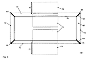
- FIG. 3 shows a third exemplary high voltage transformer module 60 in a sectional plan view.
- a dry-type transformer 62 indicated as a cuboid, is arranged centrally in a container, wherein the container is shown with its side walls 68, 70 and its end walls 72, 74 and wherein an interior space 82 is formed by the container walls.
- the transformer 62 is an integral part of a mechanical support structure 64, which is indicated in particular by outgoing at the respective vertices of the cuboid-shaped transformer 62 outgoing hollow profile connections, which pass into respective load transfer points 66.
- the heat exchangers are part of an integrated cooling system of the high voltage transformer module to carry away the waste heat generated during operation of the transformer. Particularly effective is a cooling system with a closed cooling circuit, circulating cooling medium, condenser and evaporator, which is known to those skilled in the art, however.
- Fig. 4 shows a stack 90 of two high-voltage transformer modules 92, 94, wherein the respective weight forces are removed via the load-removal points located at the respective corner points.
- stacking occurs, for example, in a ship transport. But it is also readily possible, if space permits on site, several arranged to an electrical energy system or test system interconnected container modules arranged in such a stacked for their operation.
- Fig. 5 shows a fourth transformer core 102 with winding 104, 106 in a representation 100.
- a corresponding transformer core with winding has been indicated in each case as a cuboid, whereas this is a more realistic representation example.
- transformers autotransformers, single-phase versions.
Description
Die Erfindung betrifft ein Hochspannungstransformatormodul, umfassend einen Transformatorkern mit wenigstens einer Wicklung und ein elektrisches Energiesystem mit einem Hochspannungstransformatormodul.The invention relates to a high-voltage transformer module comprising a transformer core with at least one winding and an electrical energy system with a high-voltage transformer module.
Es ist allgemein bekannt, dass Hochspannungstransformatoren, beispielsweise in einem Spannungsbereich von 110kV oder 380kV und in einem Leistungsbereich von 100MVA und höher, sowohl zu Revisionszwecken als auch nach Abschluss von eventuellen Wartungs- oder Reparaturarbeiten aber auch direkt nach ihrer Fabrikation intensiv zu prüfen sind, um deren einwandfreie Funktion für den nächsten Betriebszeitraum sicher zu stellen, was oftmals eine Vielzahl an Jahren ist. Es sind sowohl stationäre als auch mobile Prüffelder im Einsatz. Letztere werden insbesondere für eine Vor- Ort- Prüfung von Transformatoren aufgebaut, danach abgebaut und zu einem nächsten Einsatzort transportiert. Auch wenn der Transport und Aufbau eines mobilen Prüffeldes zumeist mit einem sehr hohen Aufwand verbunden ist, so ist dieser dennoch zumeist geringer, als der Aufwand, einen Transformator mit einem Gewicht von beispielsweise 200t zu einem stationären Prüffeld zu transportieren. In vorteilhafter Weise ist zudem dann die Ausfallzeit eines in Prüfung befindlichen Transformators deutlich reduziert.It is well known that high-voltage transformers, for example, in a voltage range of 110kV or 380kV and in a power range of 100MVA and higher, are to be intensively tested both for auditing purposes and after completion of any maintenance or repair work, but also directly after fabrication ensuring their proper functioning for the next operating period, which is often a multitude of years. Both stationary and mobile test fields are in use. The latter are set up in particular for on-site testing of transformers, then dismantled and transported to a next site. Even if the transport and construction of a mobile test field is usually associated with a very high cost, it is still mostly less than the effort to transport a transformer with a weight of, for example, 200 t to a stationary test field. Advantageously, then also the downtime of a transformer under test is significantly reduced.
Hierbei kommen sowohl DC als auch AC Prüffelder zum Einsatz, mit welchen die entsprechenden Prüfbedingungen hergestellt werden können. Insbesondere AC nung auf ein für die Prüfung benötigtes Spannungsniveau zu konvertieren oder aber auch, um die Spannung der zur Verfügung stehenden Einspeisung an die Wechselrichter anzupassen.Both DC and AC test fields are used, with which the corresponding test conditions can be produced. In particular, AC to convert it to a voltage level required for the test or else to adapt the voltage of the available feed to the inverters.
Ein derartiger Transformator ist aufgrund der hohen benötigten maximalen Prüfleistung - beispielsweise 20MVA und höher - eine Komponente von erheblicher Größe und erheblichem Gewicht, beispielsweise 15t. Der Transport eines solchen Transformators erfolgt in nachteiliger Weise als Sondertransport, beispielsweise auf einem Tieflader, und ist damit besonders zeit- und aufwandsintensiv. Auch der Aufbau, die Montage und Inbetriebnahme eines derartigen Prüftransformators vor Ort ist mit einem erheblichen zeitlichen und logistischen Aufwand verbunden.Such a transformer is due to the high required maximum test power - for example, 20MVA and higher - a component of considerable size and considerable weight, for example, 15t. The transport of such a transformer takes place disadvantageously as a special transport, for example on a low-loader, and is therefore particularly time-consuming and expensive. The construction, installation and commissioning of such a test transformer on site is associated with a considerable time and logistical effort.
DieThe
Ausgehend von diesem Stand der Technik ist es Aufgabe der Erfindung, einen Hochspannungstransformator beziehungsweise ein entsprechendes elektrisches Energiesystem anzugeben, welche besonders einfach zu transportieren und vor Ort aufzustellen ist.Based on this prior art, it is an object of the invention to provide a high-voltage transformer or a corresponding electrical energy system, which is particularly easy to transport and set up on site.
Diese Aufgabe wird gelöst durch ein Hochspannungstransformatormodul der eingangs genannten Art. Dieses ist dadurch gekennzeichnet, dass der Transformatorkern fest in eine mechanische Tragestruktur mit vier oberen und vier unteren quaderförmig angeordneten Eckpunkten integriert ist, wobei die Eckpunkte jeweils als Lastabtragpunkte ausgeführt und entsprechend den Abmessungen eines CSC Containers angeordnet sind.This object is achieved by a high-voltage transformer module of the aforementioned type. This is characterized in that the transformer core is firmly integrated into a mechanical support structure with four upper and four lower cuboid corner points, wherein the corner points each designed as load transfer points and according to the dimensions of a CSC Containers are arranged.
Die Grundidee der Erfindung beruht einerseits darin, ein Prüffeldsystem für Hochspannungstransformatoren aus möglichst wenigen und standardisierten Modulen aufzubauen, welche einfach zu transportieren sind und vor Ort beispielsweise durch entsprechende elektrische Steckverbindungen einfach zu einem kompletten Prüffeldsystem verschaltet werden können. Um den Transport eines Hochspannungstransformatormoduls, welches als wesentliche Komponente eines Prüffeldsystems anzusehen ist, zu vereinfachen, sind die Eckpunkte der Tragestruktur an das standardisierte Rastermaß der Eckpunkte von Standardcontainern nach CSC (International Convention for Save Containers) angepasst. CSC Container haben beispielsweise standardisierte Abmessungen von in der Breite 2,438m, in der Höhe 2,591 m und in der Länge 6,058m beziehungsweise 12,192m. Die acht Eckpunkte eines Containers formatormoduls, welches als wesentliche Komponente eines Prüffeldsystems anzusehen ist, zu vereinfachen, sind die Eckpunkte der Tragestruktur an das standardisierte Rastermaß der Eckpunkte von Standardcontainern nach CSC (International Convention for Save Containers) angepasst. CSC Container haben beispielsweise standardisierte Abmessungen von in der Breite 2,438m, in der Höhe 2,591m und in der Länge 6,058m beziehungsweise 12,192m. Die acht Eckpunkte eines Containers sind gleichzeitig seine Belastungspunkte, über welche die Gewichtskräfte nach unten abgetragen werden beziehungsweise Gewichtskräfte von darüber befindlichen Containern aufgenommen.The basic idea of the invention is, on the one hand, to construct a test field system for high-voltage transformers from as few and standardized modules as possible, which are easy to transport and can be easily connected to a complete test field system, for example by means of corresponding electrical plug-in connections. To transport a high-voltage transformer module, which is an essential component of a test field system It is considered to simplify the corner points of the support structure at the standardized spacing of the vertices of standard containers to CSC (International onvention C for S ave C ontainers) are adapted. For example, CSC containers have standardized dimensions of 2,438m in width, 2,591m in height and 6,058m and 12,192m in length, respectively. The eight corner points of a container Formormoduls, which is to be regarded as an essential component of a test field system to simplify, the vertices of the support structure are adapted to the standardized grid of the vertices of standard containers according to CSC (International C onvention for S ave C ontainers). For example, CSC containers have standardized dimensions of 2.438m in width, 2.591m in height, and 6.058m and 12.192m in length, respectively. The eight corner points of a container are at the same time its load points, over which the weight forces are removed downwards or added weight forces of containers located above it.
Die mechanische Tragestruktur ist beispielsweise als Gestell aus Edelstahlrohrprofilen geeigneter Querschnitte realisiert, wobei der Transformator dann in einer bevorzugten Variante mittig angeordnet sein kann. Der Transformator kann sowohl in ein an sich bereits tragendes Gestell integriert sein, beispielsweise indem er auf dafür vorgesehenen Auflagepunkten des Gestells mittels Schraub- oder Klemmverbindungen befestigt ist. Es ist aber auch möglich, insbesondere wenn die Größe des Transformators nahe an die Größe eines Containers herankommt, das dann eher klein ausfallende Gestell als integralen Teil des Transformators selbst auszuführen.The mechanical support structure is realized for example as a frame made of stainless steel tube profiles of suitable cross-sections, the transformer can then be arranged centrally in a preferred variant. The transformer can be integrated into a frame that is in itself already supporting, for example by being fastened to bearing points of the frame provided by means of screwed or clamped connections. But it is also possible, especially if the size of the transformer comes close to the size of a container, then run the rather small failing frame as an integral part of the transformer itself.
Somit lässt sich ein erfindungsgemäßes Hochspannungstransformatormodul wie ein Standardcontainer in einen beliebigen Containerstapel integrieren und zusammen mit diesem beispielsweise auf einem Schiff transportieren. Aber auch die Vielzahl von weiteren Transportmöglichkeiten für Standardcontainer wie beispielsweise Bahn oder LKW erschließt sich in vorteilhafter Weise für ein Hochspannungstransformatormodul, so dass dessen Transport dadurch erheblich vereinfacht wird.Thus, a high-voltage transformer module according to the invention can be integrated into any container stack like a standard container and transported together with it, for example, on a ship. But also the variety of other transport options for standard containers such as rail or truck opens up advantageously for a high voltage transformer module, so that its transport is considerably simplified.
Auch das Aufstellen des Hochspannungstransformatormoduls vor Ort wird durch die mechanische Tragestruktur, in welche der Transformator dauerhaft integriert ist, deutlich vereinfacht. Um einen sicheren Stand zu gewährleisten ist lediglich für ein Abstützen der vier unteren Lastabtragpunkte zu sorgen, beispielsweise durch geeignete Fundamentsegmente aus Beton. Die oberen vier Lastabtragpunkte dienen bei der Montage beispielsweise als Halteösen für das Abseilen durch einen Kran. Die Anordnung des Transformators mit Kern und Wicklung in der Tragestruktur ist daher so auszuführen, dass dessen isolationstechnisch sicherer Betrieb in der Tragestruktur gewährleistet ist, welche ja ein fester Bestandteil des erfindungsgemäßen Hochspannungstransformatormoduls ist. Insbesondere die isolationstechnisch bedingten Mindestabstände zu den elektrischen Anschlüssen des Transformators sind daher einzuhalten. Entsprechend einer Ausführungsvariante des Hochspannungstransformatormoduls ist der Transformator als Trockentransformator für beispielsweise einen Spannungsbereich bis 30kV, 60kV oder auch sogar bis 110kV ausgeführt. Es sind hierbei sowohl 1-phasige, 3-phasige Ausführungen als auch Sonderbauformen wie Potentialtrenner oder dergleichen denkbar.The installation of the high-voltage transformer module on site is greatly simplified by the mechanical support structure, in which the transformer is permanently integrated. To ensure a secure footing is only to provide support for the four lower load transfer points, for example, by suitable concrete foundation segments. The upper four load transfer points are used during assembly, for example, as holding eyes for rappelling by a crane. The arrangement of the transformer with core and winding in the support structure is therefore to be designed so that its isolation technology safe operation in the support structure is guaranteed, which is indeed an integral part of the high-voltage transformer module according to the invention. In particular, the insulation-related minimum distances to the electrical connections of the transformer must therefore be observed. According to one embodiment variant of the high-voltage transformer module, the transformer is designed as a dry-type transformer for example for a voltage range up to 30 kV, 60 kV or even up to 110 kV. Both 1-phase, 3-phase versions as well as special designs such as potential isolators or the like are conceivable here.
Gemäß einer weiteren Ausgestaltungsform des erfindungsgemäßen Hochspannungstransformatormoduls sind die Eckpunkte zudem als Standardcontainerecken ausgeführt, weisen also insbesondere entsprechende Bohrungen und einen inneren Hohlraum auf, so dass beispielsweise ein gegenseitiges Verspannen von aneinandergrenzenden Containerecken ermöglicht ist.According to a further embodiment of the high-voltage transformer module according to the invention, the corner points are also designed as standard container corners, thus in particular have corresponding holes and an inner cavity, so that, for example, a mutual clamping of adjacent container corners is possible.
Gemäß einer besonders bevorzugten Ausführungsform des erfindungsgemäßen Hochspannungstransformatormoduls sind die von den Eckpunkten aufgespannten Flächen als Wandung ausgebildet, so dass ein containerähnlicher Behälter mit einem Innenraum gebildet ist. Hierdurch ist insbesondere ein Transportschutz für das Hochspannungstransformatormodul gegeben, wodurch dessen Transport weiter vereinfacht ist. Eine derartige Wandung dient aber auch zum Schutz beim Betrieb. Optional ist eine Zugangsmöglichkeit - beispielsweise eine Tür - zum Inneren des containerähnlichen Behälters vorzusehen, um eine Wartung zu ermöglichen. Auch hier ist der Transformator derart auszugestalten und innerhalb des Behälters anzuordnen, dass ein isolationstechnisch sicherer Betrieb bei vorhandenen Wandungen gewährleistet ist. Die elektrischen Anschlüsse des Transformators sind dann mittels geeigneter Durchführungen, beispielsweise durch eine Seitenwandung, nach außen zu führen. Auch eine direkte Durchführung von entsprechend isolierten Kabeln ist möglich, wobei dann vorzugsweise eine jeweils herausziehbare Kabelschlaufe im Behälterinneren vorzuhalten ist.According to a particularly preferred embodiment of the high-voltage transformer module according to the invention, the surfaces spanned by the corner points are formed as walls, so that a container-like container is formed with an interior space. As a result, a transport protection for the high-voltage transformer module is given in particular, whereby its transport is further simplified. Such a wall also serves to protect during operation. Optionally, accessibility - such as a door - to the interior of the container-like container to provide for maintenance. Again, the transformer is to be designed in such a way and to arrange within the container that a safe isolation operation is ensured in existing walls. The electrical connections of the transformer are then lead by means of suitable feedthroughs, for example by a side wall, to the outside. A direct implementation of appropriately insulated cables is possible, in which case preferably a respective retractable cable loop is to be provided in the container interior.
Um eine völlige Kompatibilität eines erfindungsgemäßen Hochspannungstransformatormoduls mit bestehenden Containertransportsystemen zu gewährleisten, ist der Behälter vorzugsweise als Container entsprechend CSC ausgeführt.In order to ensure complete compatibility of a high-voltage transformer module according to the invention with existing container transport systems, the container is preferably designed as a container according to CSC.
Einer weiteren Erfindungsvariante folgend sind die Wandungen zumindest bereichsweise jeweils doppelwandig ausgeführt. Hierdurch wird die Schutzfunktion der Wandung weiter erhöht, so dass auch bei Beschädigung einer Wandung ein Schutz durch die zweite Wandung gegeben ist.According to another variant of the invention, the walls are at least partially executed in each case double-walled. As a result, the protective function of the wall is further increased, so that even if a wall is damaged, a protection by the second wall is given.
Erfindungsgemäß ist einer weiteren Variante folgend wenigstens eine Querwandung im Innenraum vorgesehen, durch welche dieser in wenigstens einen ersten und einen zweiten Innenraum geteilt ist, wobei der Transformatorkern mit Wicklung im ersten Innenraum angeordnet ist. Die Teilung des gemeinsamen Innenraums in einen ersten und einen zweiten Innenraum ermöglicht beispielsweise die Integration weiterer Komponenten eines Gesamtsystems in das Hochspannungstransformatormodul, welche dann in vorteilhafter Weise durch die Querwandung vom Transformator getrennt im zweiten Innenraum angeordnet sind. Diese Ausführungsvariante ist jedoch nur bei geringeren Transformatorleistungen möglich, wo noch ein entsprechender Platz im Innenraum des containerähnlichen Behälters zur Verfügung steht.According to the invention, according to another variant, at least one transverse wall is provided in the inner space, by which it is divided into at least a first and a second inner space, wherein the transformer core with winding is arranged in the first inner space. The division of the common interior into a first and a second interior, for example, allows the integration of further components of an overall system in the high-voltage transformer module, which are then arranged in an advantageous manner by the transverse wall of the transformer in the second interior. However, this variant is possible only at lower transformer powers, where there is still a corresponding space in the interior of the container-like container available.
Einer speziellen Ausführungsvariante folgend sind der gemeinsame Innenraum beziehungsweise der erste Innenraum, wo je nach Variante der Transformator angeordnet ist, hermetisch dicht ausgeführt. Dies ermöglicht nämlich das Füllen des betreffenden Innenraums mit einem Transformatoröl, so dass der darin befindliche Transformator letztendlich als Öltransformator ausgebildet ist. Dies ist aufgrund der Isolatoreigenschaft von Öl insbesondere bei höheren als den zuvor angegebenen Spannungen von Interesse, beispielsweise bei 110kV und höher. Der erste Innenraum dient dann als Transformatorkessel und ist auch entsprechend dem Kessel eines Öltransformators beispielsweise mit Barrieren auszugestalten, wobei dann auch vorzugsweise vor Ort zu montierende Ausleitungen benötigt werden. Ebenso sollte die Befüllung des Kessels mit Öl vorzugsweise vor Ort erfolgen, um so das Transportgewicht nicht zu groß werden zu lassen. Aus Sicherheitsgründen sollte der jeweils mit Öl gefüllte beziehungsweise zu füllende Innenraum von einer Doppelwandung umgeben sein.Following a specific embodiment, the common interior or the first interior, where arranged depending on the variant of the transformer, hermetically sealed. Namely, this makes it possible to fill the respective inner space with a transformer oil, so that the transformer therein is ultimately designed as an oil transformer. This is of interest due to the isolator nature of oil, especially at higher than the previously indicated voltages, for example at 110kV and higher. The first interior then serves as a transformer tank and is also to design according to the boiler of an oil transformer, for example, with barriers, which then also preferably to be mounted on site discharges are needed. Likewise, the filling of the boiler with oil should preferably be done on site, so as not to let the transport weight be too large. For safety reasons, each filled with oil or to be filled interior should be surrounded by a double wall.
Entsprechend einer weiteren Variante des erfindungsgemäßen Hochspannungstransformatormoduls ist innerhalb des Innenraums beziehungsweise des zweitenAccording to a further variant of the high-voltage transformer module according to the invention is within the interior or the second
Innenraums eine galvanisch mit der wenigstens einen Wicklung des Transformators verbundene elektrische Schaltanlage vorgesehen. Optional ist es aber auch innerhalb des Innenraums beziehungsweise des zweiten Innenraums wenigstens ein galvanisch mit der wenigstens einen Wicklung verbundener Wechsel- und/oder Gleichrichter vorgesehen. Beide Ausführungsformen erschließen sich selbstverständlich nur bei einem noch ausreichenden Platzangebot innerhalb des Containers beziehungsweise containerähnlichen Behälters, also beispielsweise bei einer Transformatorleistung von nur wenigen MVA. Auf diese Weise lassen sich in vorteilhafter Weise weitere Bestandteile eines modularen Gesamtsystems in das Hochspannungstransformatormodul integrieren und die Zahl der benötigten Gesamtmodule somit reduzieren.Interior an electrically connected to the at least one winding of the transformer electrical switchgear provided. Optionally, however, it is also provided within the interior or the second interior at least one galvanically connected to the at least one winding AC and / or rectifier. Of course, both embodiments are only accessible if there is still sufficient space inside the container or container-like container, that is, for example, with a transformer output of only a few MVA. In this way, further components of a modular overall system can advantageously be integrated into the high-voltage transformer module and the number of total modules required can thus be reduced.
Gemäß einer bevorzugten Erfindungsvariante ist innerhalb des Innenraums beziehungsweise des ersten und/oder zweiten Innenraums ein Kühlsystem mit wenigstens einem Wärmeübertrager vorgesehen, wobei fernerhin eine Bewegungsvorrichtung vorgesehen ist, mittels welcher der wenigstens eine Wärmeübertrager von einer Transportposition innerhalb eines der Innenräume in eine zumindest teilweise außerhalb befindliche Arbeitsposition bewegbar ist.According to a preferred variant of the invention, a cooling system with at least one heat exchanger is provided within the interior or the first and / or second interior, wherein furthermore a movement device is provided, by means of which the at least one heat exchanger from a transport position within one of the interior spaces in an at least partially located outside Working position is movable.
Transformatoren erzeugen in ihrem Betrieb eine elektrische Verlustleistung, welche zu einem Wärmeeintrag in den Container führt. Insbesondere bei Anordnung des Transformators in einem geschlossenen containerähnlichen Behälter führt dies schnell zu einem unzulässig hohen Temperaturanstieg innerhalb des Behälters. Dieser Effekt wird auch durch andere Verlustwärme produzierende Komponenten innerhalb des Behälters unterstützt, insbesondere auch durch Umrichterschränke mit ihrer Leistungselektronik. Deshalb ist die Problematik der Abfuhr von im Betrieb entstehender Verlustwärme von besonderer Bedeutung.Transformers generate in their operation an electrical power loss, which leads to a heat input into the container. In particular, in the arrangement of the transformer in a closed container-like container, this quickly leads to an inadmissibly high temperature rise within the container. This effect is also supported by other loss-heat producing components within the container, in particular by inverter cabinets with their power electronics. Therefore, the problem of the removal of heat generated during operation of particular importance.
Der erfindungsgemäße Vorteil des Kühlsystems entsprechend dieser Erfindungsvariante liegt in einer besonders platzsparenden und kompakten Anordnung des Wärmetauschers zu Transportzwecken innerhalb des Hochspannungstransformatormoduls, wobei zum Betrieb des Hochspannungstransformatormoduls der Wärmetauscher zumindest teilweise aus diesem herausbewegt ist. Aufgrund der dann erhöhten Kontaktfläche mit der Umgebungsluft ist eine deutlich erhöhte Effizienz des Kühlsystems erreicht. Vorzugsweise ist ein derartiges Kühlsystem als geschlossener Kühlkreislauf mit Kondensator und Verdampfer ausgeführt, wobei der oder auch mehrere Verdampfer durch Verdampfen der Kühlflüssigkeit Wärmeenergie im Inneren des Hochspannungstransformatormoduls aufnehmen und an den heraus bewegbaren Kondensator abgeben. Ein derartiger Kondensator ist beispielsweise im oberen Bereich des Prüffeldmoduls angeordnet und schubladenähnlich aus diesem durch eine jeweilige Öffnung heraus fahrbar. Durch ein auf die Oberfläche des Kondensators gerichtetes Gebläse ist die Effizienz eines derartigen Kühlsystems bedarfsweise noch zu steigern.The advantage of the cooling system according to the invention according to this variant of the invention lies in a particularly space-saving and compact arrangement of the heat exchanger for transport purposes within the high voltage transformer module, wherein the heat exchanger is at least partially moved out of this for operation of the high voltage transformer module. Due to the then increased contact surface with the ambient air is a significantly increased efficiency of the cooling system reached. Preferably, such a cooling system is designed as a closed cooling circuit with a condenser and evaporator, wherein the or more evaporators absorb heat energy by evaporation of the cooling liquid in the interior of the high voltage transformer module and deliver it to the movable capacitor. Such a capacitor is arranged for example in the upper region of the test field module and drawer-like movable out of this through a respective opening out. By a directed to the surface of the condenser fan, the efficiency of such a cooling system, if necessary, to increase.
Gemäß einer bevorzugten Variante des Hochspannungstransformatormoduls ist in wenigstens einer Wandung wenigstens eine mittels einer Abdeckung verschließbare Aussparung vorgesehen. Die Aussparung dient insbesondere der Durchführung der elektrischen Versorgungsleitungen oder Anschlüsse des Hochspannungstransformatormoduls, so dass diese problemlos elektrisch mit weiteren Modulen eines Gesamtsystems verbindbar ist. Die Abdeckung dient dem Schutz bei einem Transport. Nach der Aufstellung vor Ort ist kein Schutz mehr erforderlich und die Abdeckung kann entfernt werden, so dass die Aussparung offengelegt ist. Durch diese können dann entweder - bedarfsweise unter Verwendung einer dem Fachmann bekannten jeweiligen elektrischen Durchführung - direkt entsprechend isolierte Anschlusskabel geführt werden. Es kann aber auch beispielsweise eine Klemmleiste für entsprechende elektrische Anschlüsse eingesetzt werden, welche während des Transportes im Inneren des Containers gelagert wurde und bereits alle rückwärtigen modulinternen Verbindungen, beispielsweise zum Transformator, aufweist. Auf diese Weise sind sowohl ein sicherer Transport ohne Störkontur an der Anschlussstelle als auch ein einfaches Verschalten des Hochspannungstransformatormoduls mit weiteren Modulen gewährleistet.According to a preferred variant of the high-voltage transformer module, at least one recess which can be closed by means of a cover is provided in at least one wall. The recess serves, in particular, to carry out the electrical supply lines or connections of the high-voltage transformer module, so that it can easily be electrically connected to other modules of an overall system. The cover serves to protect during transport. After installation on site, protection is no longer required and the cover can be removed so that the recess is exposed. Through these can then either - if necessary, using a known to those skilled in each electrical implementation - directly corresponding insulated connection cables are performed. But it can also be used, for example, a terminal block for corresponding electrical connections, which was stored during transport inside the container and already has all the rear module-internal connections, for example, to the transformer. In this way, both a secure transport without interference contour at the junction and a simple interconnection of the high-voltage transformer module with other modules are guaranteed.
Die Aufgabe wird auch gelöst durch ein elektrisches Energiesystem, welches modular aufgebaut ist und wenigstens ein erfindungsgemäßes Hochspannungstransformatormodul umfasst. Wie eingangs erwähnt ermöglicht der modulare Aufbau, vorzugsweise unter Verwendung von Containern oder containerähnlichen Behältern als Gehäuse, einen einfachen Transport und problemlosen Aufbau vor Ort, insbesondere weil die Systemkomponenten in einer festen Position innerhalb des Containers angeordnet sind. In ihrer festen Position sind die Komponenten containerintern bereits fest verschaltet, so dass lediglich noch das Modul als solches zu verschalten ist. Die Modularität ermöglicht zudem ein bedarfsweises elektrisches Zusammenschalten von mehreren standardisierten und containerbasierten Systemmodulen, wie beispielsweise auch Umrichtermodulen, zu einem elektrischen Energiesystem. So ist beispielsweise die Leistung eines modularen elektrischen Energiesystems durch Implementierung weiterer containerbasierter Systemmodule entsprechend steigerbar.The object is also achieved by an electrical energy system which has a modular design and comprises at least one high-voltage transformer module according to the invention. As mentioned earlier, the modular construction, preferably using containers or container-like containers as a housing, enables easy transportation and easy installation on site, especially because the system components are arranged in a fixed position within the container are. In their fixed position, the components are already permanently interconnected within the container, so that only the module has to be interconnected as such. The modularity also allows a demand-based electrical interconnection of several standardized and container-based system modules, such as converter modules, to an electrical energy system. For example, the performance of a modular electrical energy system can be increased accordingly by implementing further container-based system modules.
Vorzugsweise ist das modulare elektrische Energiesystem ein Prüffeldsystem für Leistungstransformatoren, ist also dafür vorgesehen, die vorgegebene Spannung einer elektrischen Einspeisung in eine Prüffspannung (ein- oder auch dreiphasig) mit variabler Höhe und Frequenz zu konvertieren. Selbstverständlich ist ein containerbasiertes modulares elektrisches Energiesystem aber auch für andere Anwendungszwecke geeignet, beispielsweise auch als Energiesystem für Windparks beziehungsweise auch Offshore - Windparks. Ein Hochspannungstransformatormodul in seiner Containerausführung mit Transformator und Umrichtern beispielsweise ist ohne weiteres derart konzipierbar, dass es als Umformer / Umrichter für eine Windkraftanlage geeignet ist. Die Aufgabe von einem derartigen Umrichter für Windkraftanlagen ist die Umformung einer erzeugten variablen Spannung in eine definierte Einspeisespannung, und damit letztendlich sehr vergleichbar mit der Aufgabe eines Prüffeldsystems. Die Vorteile eines derart ausgeführten erfindungsgemäßen Hochspannungstransformatormoduls, nämlich seine einfache Transportierbarkeit und Montage vor Ort, ist bei der Errichtung von Windparks ebenfalls von höchster Bedeutung, so dass die Erfindung auch in diesem Bereich vorteilhaft eingesetzt werden kann.Preferably, the modular electrical energy system is a test field system for power transformers, so it is intended to convert the predetermined voltage of an electrical feed into a test voltage (single or three-phase) with variable height and frequency. Of course, a container-based modular electrical energy system is also suitable for other applications, for example, as an energy system for wind farms and offshore - wind farms. A high-voltage transformer module in its container design with transformer and converters, for example, is readily conceivable so that it is suitable as a converter / converter for a wind turbine. The object of such a converter for wind power plants is the transformation of a generated variable voltage into a defined supply voltage, and thus ultimately very similar to the task of a test field system. The advantages of such a high-voltage transformer module according to the invention, namely its ease of transport and installation on site, are also of paramount importance in the construction of wind farms, so that the invention can also be advantageously used in this area.
Weitere vorteilhafte Ausgestaltungsmöglichkeiten sind den weiteren abhängigen Ansprüchen zu entnehmen.Further advantageous embodiment possibilities can be found in the further dependent claims.
Anhand der in den Zeichnungen dargestellten Ausführungsbeispiele sollen die Erfindung, weitere Ausführungsformen und weitere Vorteile näher beschrieben werden.Reference to the embodiments illustrated in the drawings, the invention, further embodiments and other advantages will be described in detail.
Es zeigen:
- Fig. 1
- ein erstes exemplarisches Hochspannungstransformatormodul,
- Fig. 2
- ein zweites exemplarisches Hochspannungstransformatormodul,
- Fig. 3
- ein drittes exemplarisches Hochspannungstransformatormodul,
- Fig. 4
- eine Stapelung von Hochspannungstransformatormodulen sowie
- Fig. 5
- einen vierten Transformatorkern mit Wicklung.
- Fig. 1
- a first exemplary high voltage transformer module,
- Fig. 2
- a second exemplary high voltage transformer module,
- Fig. 3
- a third exemplary high voltage transformer module,
- Fig. 4
- a stack of high voltage transformer modules as well
- Fig. 5
- a fourth transformer core with winding.
Die Flächenbereiche zwischen den Lastabtragpunkten sind doppelwandig als Wandungen 18, 20 ausgeprägt, so dass ein containerähnlicher Behälter mit Innenraum gebildet ist. Es ist fernerhin zwischen den Seitenwandungen eine doppelwandige innere Querwandung 24, 26 vorgesehen, so dass ein doppelwandig umhüllter hermetisch dichter erster Innenraum 36 und ein daran angrenzender zweiter Innenraum 38 gebildet sind. Der erste doppelwandig umhüllte Innenraum 36, in welchem der Transformator 12 angeordnet ist, ist ölgefüllt und im zweiten Innenraum 38 ist eine dreiphasige elektrische Schaltanlage 32 angeordnet. Diese ist über galvanische Verbindungsleiter 34 mit dem Transformator 12 verbunden, wobei diese mittels hermetisch dichtender Durchführungen 28 durch die innere Querwandung 24, 26 in den ersten ölgefüllten Innenraum 36 geführt sind. Die Durchführungen entsprechen von ihrer Ausführungen dem Fachmann bekannten Durchführungen. Die Schaltanlage 32 ist weiterhin mittels dreier galvanischer Verbindungsleiter 34 mit einem außerhalb des containerähnlichen Behälters liegenden weiteren Containermodul verbunden, wobei diese Leiter durch entsprechende Durchführungen an der äußeren Stirnwand geführt sind.The areas between the load transfer points are double-walled as
- 1010
- erstes exemplarisches Hochspannungstransformatormodulfirst exemplary high-voltage transformer module
- 1212
- erster Transformatorkern mit Wicklungfirst transformer core with winding
- 1414
- erste mechanische Tragestrukturfirst mechanical support structure
- 1616
- LastabtragpunkteLastabtragpunkte
- 1818
- äußere Wandungouter wall
- 2020
- innere Wandunginner wall
- 2222
- Hohlraum zwischen äußerer und innerer WandungCavity between outer and inner wall
- 2424
- äußere Querwandungouter transverse wall
- 2626
- innere Querwandunginner transverse wall
- 2828
- innere Durchführunginternal execution
- 3030
- äußere Durchführungouter implementation
- 3232
- elektrische Schaltanlageelectrical switchgear
- 3434
- galvanische Verbindunggalvanic connection
- 3636
- mit Öl gefüllter erster Innenraumfilled with oil first interior
- 3838
- zweiter Innenraumsecond interior
- 4040
- zweites exemplarisches Hochspannungstransformatormodulsecond exemplary high voltage transformer module
- 4444
- untere Lastabtragpunktelower load transfer points
- 4646
- obere Lastabtragpunkteupper load transfer points
- 4848
- zweiter Transformatorkern mit Wicklungsecond transformer core with winding
- 5050
- containerähnlicher Behältercontainer-like container
- 6060
- drittes exemplarisches Hochspannungstransformatormodulthird exemplary high voltage transformer module
- 6262
- dritter Transformatorkern mit Wicklungthird transformer core with winding
- 6464
- zweite mechanische Tragestruktursecond mechanical support structure
- 6666
- LastabtragpunkteLastabtragpunkte
- 6868
- erste Seitenwandungfirst side wall
- 7070
- zweite Seitenwandungsecond side wall
- 7272
- erste Stirnwandungfirst end wall
- 7474
- zweite Stirnwandungsecond end wall
- 7676
- Wärmeübertrager in TransportpositionHeat exchanger in transport position
- 7878
- Wärmeübertrager in ArbeitspositionHeat exchanger in working position
- 8080
- Bewegungsrichtungmovement direction
- 8282
- Innenrauminner space
- 9090
- Stapelung von HochspannungstransformatormodulenStacking of high voltage transformer modules
- 9292
- erstes Hochspannungstransformatormodulfirst high-voltage transformer module
- 9494
- zweites Hochspannungstransformatormodulsecond high voltage transformer module
- 9696
- Kraftübertragung an LastabtragpunktenPower transmission at load transfer points
- 100100
- vierter Transformatorkern mit Wicklungfourth transformer core with winding
- 102102
- Transformatorkerntransformer core
- 104104
- erste Wicklungfirst winding
- 106106
- zweite Wicklungsecond winding
Claims (15)
- High-voltage transformer module (10, 40, 60, 92, 94), comprising a transformer core having at least one winding (12, 48, 62, 100), characterized in that the transformer core (102) is fixedly integrated in a mechanical supporting structure having four upper and four lower corner points arranged in the form of a square, wherein the corner points are each in the form of load transfer points (16, 44, 46, 66) and are arranged corresponding to the dimensions of a CSC container.
- High-voltage transformer module according to Claim 1, characterized in that the corner points are in the form of standard container corners.
- High-voltage transformer module according to Claim 2, characterized in that the areas spanned by the corner points are each in the form of a wall (18, 68, 70, 72, 74), with the result that a container-like receptacle (50) with an interior (82) is formed.
- High-voltage transformer module according to Claim 3, characterized in that the container-like receptacle (50) is in the form of a container adhering to CSC.
- High-voltage transformer module according to either of Claims 3 and 4, characterized in that the walls (18, 68, 70, 72, 74) are each formed at least regionally as double walls (18-20).
- High-voltage transformer module according to one of Claims 3 to 5, characterized in that at least one transverse wall (24, 26) is provided in the interior (82), by means of which transverse wall said interior (82) is divided into at least one first interior (36) and one second interior (38), wherein the transformer core with the winding (12, 48, 62, 100) is arranged in the first interior (36).
- High-voltage transformer module according to one of Claims 3 to 6, characterized in that the interior (82) or the first interior (36) is hermetically sealed.
- High-voltage transformer module according to Claim 7, characterized in that the interior (82) or the first interior (36) is filled with an oil.
- High-voltage transformer module according to one of Claims 3 to 8, characterized in that an electrical switchgear assembly (32), which is connected (34) galvanically to the at least one winding (102, 104), is provided within the interior (82) or the second interior (38).
- High-voltage transformer module according to one of Claims 3 to 9, characterized in that at least one inverter and/or rectifier, which is connected (34) galvanically to the at least one winding (102, 104), is provided within the interior (82) or the second interior (38).
- High-voltage transformer module according to one of Claims 3 to 10, characterized in that a cooling system comprising at least one heat exchanger (76) is provided within the interior (82) or the first and/or second interior (38), wherein, furthermore, a movement apparatus is provided, by means of which the at least one heat exchanger (76) is movable (80) from a transport position within one of the interiors (38, 82) into a working position (78) which is located at least partially outside.
- High-voltage transformer module according to one of Claims 3 to 11, characterized in that at least one cutout, which can be closed by means of a cover, is provided in at least one wall (18, 20, 24, 26, 68, 70, 72, 74).
- High-voltage transformer module according to Claim 12, characterized in that an electrical bushing (28, 30) is arranged in an interior (36, 38, 82) through the at least one cutout.
- Electrical energy system, characterized in that said electrical energy system has a modular design and comprises at least one high-voltage transformer module according to one of Claims 1 to 13.
- Electrical energy system according to Claim 14, characterized in that said electrical energy system is a testing station system for power transformers.
Priority Applications (7)
| Application Number | Priority Date | Filing Date | Title |
|---|---|---|---|
| ES11008721.0T ES2460628T3 (en) | 2011-11-02 | 2011-11-02 | High voltage transformer module |
| EP11008721.0A EP2590185B1 (en) | 2011-11-02 | 2011-11-02 | High voltage transformer module |
| RU2014122175/07A RU2566676C1 (en) | 2011-11-02 | 2012-10-16 | High-voltage transformer module |
| PCT/EP2012/004302 WO2013170870A2 (en) | 2011-11-02 | 2012-10-16 | High-voltage transformer module |
| CN201280053568.9A CN104025216B (en) | 2011-11-02 | 2012-10-16 | High-tension transformer module |
| UAA201404555A UA111380C2 (en) | 2011-11-02 | 2012-10-16 | High-voltage transformer module |
| US14/268,477 US9336939B2 (en) | 2011-11-02 | 2014-05-02 | High-voltage transformer module |
Applications Claiming Priority (1)
| Application Number | Priority Date | Filing Date | Title |
|---|---|---|---|
| EP11008721.0A EP2590185B1 (en) | 2011-11-02 | 2011-11-02 | High voltage transformer module |
Publications (2)
| Publication Number | Publication Date |
|---|---|
| EP2590185A1 EP2590185A1 (en) | 2013-05-08 |
| EP2590185B1 true EP2590185B1 (en) | 2014-04-02 |
Family
ID=45033657
Family Applications (1)
| Application Number | Title | Priority Date | Filing Date |
|---|---|---|---|
| EP11008721.0A Not-in-force EP2590185B1 (en) | 2011-11-02 | 2011-11-02 | High voltage transformer module |
Country Status (7)
| Country | Link |
|---|---|
| US (1) | US9336939B2 (en) |
| EP (1) | EP2590185B1 (en) |
| CN (1) | CN104025216B (en) |
| ES (1) | ES2460628T3 (en) |
| RU (1) | RU2566676C1 (en) |
| UA (1) | UA111380C2 (en) |
| WO (1) | WO2013170870A2 (en) |
Families Citing this family (6)
| Publication number | Priority date | Publication date | Assignee | Title |
|---|---|---|---|---|
| EP2853908B1 (en) * | 2013-09-25 | 2021-03-31 | ABB Power Grids Switzerland AG | Test system for high voltage components |
| DE102013111018A1 (en) * | 2013-10-04 | 2015-04-09 | Abb Technology Ag | Carrier structure for power electronics |
| EP3057112B1 (en) * | 2015-02-16 | 2020-05-20 | ABB Power Grids Switzerland AG | Oil transformer |
| EP3343575B1 (en) * | 2016-12-28 | 2020-03-18 | ABB Schweiz AG | A pressure compensator of a subsea installation |
| FR3074599B1 (en) * | 2017-12-05 | 2019-12-20 | Alstom Transport Technologies | RAIL TRACTION BLOCK TEST SYSTEM |
| GB2576514A (en) * | 2018-08-20 | 2020-02-26 | Comet Ag | Heat dissipation in an eletronic circuit and method |
Family Cites Families (16)
| Publication number | Priority date | Publication date | Assignee | Title |
|---|---|---|---|---|
| SU565332A1 (en) * | 1974-01-23 | 1977-07-15 | Московский Электрозавод Им.В.В.Куйбышева | Electroinduction apparatus |
| SU773753A1 (en) * | 1979-02-01 | 1980-10-23 | Предприятие П/Я А-1274 | Assembly for mounting unit in a casing |
| US5171113A (en) * | 1990-09-24 | 1992-12-15 | Buffers Ab | Removable cushioned container flat |
| EP2310926B1 (en) * | 2006-06-01 | 2013-11-20 | Google Inc. | Modular computing environments |
| US7551971B2 (en) * | 2006-09-13 | 2009-06-23 | Sun Microsystems, Inc. | Operation ready transportable data center in a shipping container |
| US8047904B2 (en) * | 2006-09-13 | 2011-11-01 | Oracle America, Inc. | Cooling method for a data center in a shipping container |
| US8763414B2 (en) * | 2008-03-31 | 2014-07-01 | Google Inc. | Warm floor data center |
| US20090242552A1 (en) * | 2008-04-01 | 2009-10-01 | Myers Gerald D | Iso container having a load transfer plate |
| ATE522817T1 (en) * | 2008-06-12 | 2011-09-15 | Abb Technology Ag | TEST ARRANGEMENT FOR AC VOLTAGE TESTING OF HIGH-VOLTAGE ELECTRICAL COMPONENTS |
| ES2374957T3 (en) * | 2008-06-12 | 2012-02-23 | Abb Technology Ag | TEST DEVICE FOR THE TRANSITORY TENSION TEST OF HIGH VOLTAGE ELECTRICAL COMPONENTS. |
| EP2133889A1 (en) * | 2008-06-12 | 2009-12-16 | ABB Technology AG | Choke and test assembly with choke |
| CN101355238B (en) * | 2008-09-19 | 2011-12-07 | 沈阳福林特种变压器有限公司 | Vehicle-mounted mobile substation |
| US8415829B2 (en) * | 2009-06-02 | 2013-04-09 | Vdc Manufacturing Inc. | Transportable modular multi-appliance device |
| US9670689B2 (en) * | 2010-04-06 | 2017-06-06 | Schneider Electric It Corporation | Container based data center solutions |
| CN201946414U (en) * | 2011-01-20 | 2011-08-24 | 山东华驰变压器股份有限公司 | Transformer body locating structure |
| US9166384B2 (en) * | 2011-04-28 | 2015-10-20 | Mitsubishi Electric Corporation | Switchgear |
-
2011
- 2011-11-02 EP EP11008721.0A patent/EP2590185B1/en not_active Not-in-force
- 2011-11-02 ES ES11008721.0T patent/ES2460628T3/en active Active
-
2012
- 2012-10-16 RU RU2014122175/07A patent/RU2566676C1/en active
- 2012-10-16 UA UAA201404555A patent/UA111380C2/en unknown
- 2012-10-16 WO PCT/EP2012/004302 patent/WO2013170870A2/en active Application Filing
- 2012-10-16 CN CN201280053568.9A patent/CN104025216B/en not_active Expired - Fee Related
-
2014
- 2014-05-02 US US14/268,477 patent/US9336939B2/en active Active
Also Published As
| Publication number | Publication date |
|---|---|
| CN104025216A (en) | 2014-09-03 |
| US9336939B2 (en) | 2016-05-10 |
| WO2013170870A3 (en) | 2014-01-09 |
| CN104025216B (en) | 2017-06-23 |
| UA111380C2 (en) | 2016-04-25 |
| WO2013170870A2 (en) | 2013-11-21 |
| US20140240901A1 (en) | 2014-08-28 |
| ES2460628T3 (en) | 2014-05-14 |
| RU2566676C1 (en) | 2015-10-27 |
| EP2590185A1 (en) | 2013-05-08 |
Similar Documents
| Publication | Publication Date | Title |
|---|---|---|
| EP2590185B1 (en) | High voltage transformer module | |
| EP3427275B1 (en) | Replacement transformer having a modular structure | |
| EP2133704B1 (en) | Test assembly for AC testing of high voltage electrical components | |
| EP2696358B1 (en) | Medium frequency transformer | |
| EP2345120A2 (en) | Device comprising rigid connecting bars for the conducting connection of first to second busbars | |
| EP2941822B1 (en) | Converter station with diode rectifier | |
| DE212011100212U1 (en) | Frame for a modular voltage-driven converter and insulation device | |
| DE1803363A1 (en) | Electric medium voltage line for power transmission | |
| EP2523196B1 (en) | Coil fixing device | |
| EP0446836B1 (en) | Current rectifier module | |
| EP2590490B1 (en) | Test container | |
| DE202014004372U1 (en) | Offshore wind farm with at least one sea-side substation | |
| EP3231054A1 (en) | Power factor correction module for use at rated voltages of substantially greater than 1000 v | |
| EP2811159B1 (en) | Plant for the production of wind energy at sea | |
| EP2641309A1 (en) | Switch panel for high-voltage switchgear assembly and method for constructing said switch panel | |
| EP3711127A1 (en) | Cable reel for a high-voltage cable | |
| EP3764376B1 (en) | Compensation device for power supply networks | |
| EP1463173B1 (en) | Metal-clad gas-insulated switchgear | |
| EP3435388B1 (en) | Arrangement for the regulation of voltage changes in a medium-voltage current network | |
| DE1226199B (en) | Transformer or reactor that can be dismantled into parts | |
| EP2590278A1 (en) | High performance test field module | |
| EP2853908B1 (en) | Test system for high voltage components | |
| DE2554514C3 (en) | Transformer for large electrical outputs | |
| WO2021191457A1 (en) | Mobile gas-insulated switch panel | |
| WO2018162162A1 (en) | Support assembly, and transformer with support assembly |
Legal Events
| Date | Code | Title | Description |
|---|---|---|---|
| PUAI | Public reference made under article 153(3) epc to a published international application that has entered the european phase |
Free format text: ORIGINAL CODE: 0009012 |
|
| AK | Designated contracting states |
Kind code of ref document: A1 Designated state(s): AL AT BE BG CH CY CZ DE DK EE ES FI FR GB GR HR HU IE IS IT LI LT LU LV MC MK MT NL NO PL PT RO RS SE SI SK SM TR |
|
| AX | Request for extension of the european patent |
Extension state: BA ME |
|
| 17P | Request for examination filed |
Effective date: 20130812 |
|
| RIC1 | Information provided on ipc code assigned before grant |
Ipc: H01F 27/00 20060101AFI20130912BHEP |
|
| GRAP | Despatch of communication of intention to grant a patent |
Free format text: ORIGINAL CODE: EPIDOSNIGR1 |
|
| INTG | Intention to grant announced |
Effective date: 20131127 |
|
| GRAS | Grant fee paid |
Free format text: ORIGINAL CODE: EPIDOSNIGR3 |
|
| GRAA | (expected) grant |
Free format text: ORIGINAL CODE: 0009210 |
|
| AK | Designated contracting states |
Kind code of ref document: B1 Designated state(s): AL AT BE BG CH CY CZ DE DK EE ES FI FR GB GR HR HU IE IS IT LI LT LU LV MC MK MT NL NO PL PT RO RS SE SI SK SM TR |
|
| REG | Reference to a national code |
Ref country code: GB Ref legal event code: FG4D Free format text: NOT ENGLISH |
|
| REG | Reference to a national code |
Ref country code: AT Ref legal event code: REF Ref document number: 660554 Country of ref document: AT Kind code of ref document: T Effective date: 20140415 Ref country code: CH Ref legal event code: EP |
|
| REG | Reference to a national code |
Ref country code: IE Ref legal event code: FG4D Free format text: LANGUAGE OF EP DOCUMENT: GERMAN |
|
| REG | Reference to a national code |
Ref country code: ES Ref legal event code: FG2A Ref document number: 2460628 Country of ref document: ES Kind code of ref document: T3 Effective date: 20140514 |
|
| REG | Reference to a national code |
Ref country code: DE Ref legal event code: R096 Ref document number: 502011002566 Country of ref document: DE Effective date: 20140515 |
|
| REG | Reference to a national code |
Ref country code: NL Ref legal event code: VDEP Effective date: 20140402 |
|
| REG | Reference to a national code |
Ref country code: LT Ref legal event code: MG4D |
|
| PG25 | Lapsed in a contracting state [announced via postgrant information from national office to epo] |
Ref country code: NO Free format text: LAPSE BECAUSE OF FAILURE TO SUBMIT A TRANSLATION OF THE DESCRIPTION OR TO PAY THE FEE WITHIN THE PRESCRIBED TIME-LIMIT Effective date: 20140702 Ref country code: FI Free format text: LAPSE BECAUSE OF FAILURE TO SUBMIT A TRANSLATION OF THE DESCRIPTION OR TO PAY THE FEE WITHIN THE PRESCRIBED TIME-LIMIT Effective date: 20140402 Ref country code: BG Free format text: LAPSE BECAUSE OF FAILURE TO SUBMIT A TRANSLATION OF THE DESCRIPTION OR TO PAY THE FEE WITHIN THE PRESCRIBED TIME-LIMIT Effective date: 20140702 Ref country code: CY Free format text: LAPSE BECAUSE OF FAILURE TO SUBMIT A TRANSLATION OF THE DESCRIPTION OR TO PAY THE FEE WITHIN THE PRESCRIBED TIME-LIMIT Effective date: 20140402 Ref country code: IS Free format text: LAPSE BECAUSE OF FAILURE TO SUBMIT A TRANSLATION OF THE DESCRIPTION OR TO PAY THE FEE WITHIN THE PRESCRIBED TIME-LIMIT Effective date: 20140802 Ref country code: NL Free format text: LAPSE BECAUSE OF FAILURE TO SUBMIT A TRANSLATION OF THE DESCRIPTION OR TO PAY THE FEE WITHIN THE PRESCRIBED TIME-LIMIT Effective date: 20140402 Ref country code: CZ Free format text: LAPSE BECAUSE OF FAILURE TO SUBMIT A TRANSLATION OF THE DESCRIPTION OR TO PAY THE FEE WITHIN THE PRESCRIBED TIME-LIMIT Effective date: 20140402 Ref country code: LT Free format text: LAPSE BECAUSE OF FAILURE TO SUBMIT A TRANSLATION OF THE DESCRIPTION OR TO PAY THE FEE WITHIN THE PRESCRIBED TIME-LIMIT Effective date: 20140402 Ref country code: GR Free format text: LAPSE BECAUSE OF FAILURE TO SUBMIT A TRANSLATION OF THE DESCRIPTION OR TO PAY THE FEE WITHIN THE PRESCRIBED TIME-LIMIT Effective date: 20140703 |
|
| PG25 | Lapsed in a contracting state [announced via postgrant information from national office to epo] |
Ref country code: RS Free format text: LAPSE BECAUSE OF FAILURE TO SUBMIT A TRANSLATION OF THE DESCRIPTION OR TO PAY THE FEE WITHIN THE PRESCRIBED TIME-LIMIT Effective date: 20140402 Ref country code: HR Free format text: LAPSE BECAUSE OF FAILURE TO SUBMIT A TRANSLATION OF THE DESCRIPTION OR TO PAY THE FEE WITHIN THE PRESCRIBED TIME-LIMIT Effective date: 20140402 Ref country code: SE Free format text: LAPSE BECAUSE OF FAILURE TO SUBMIT A TRANSLATION OF THE DESCRIPTION OR TO PAY THE FEE WITHIN THE PRESCRIBED TIME-LIMIT Effective date: 20140402 Ref country code: PL Free format text: LAPSE BECAUSE OF FAILURE TO SUBMIT A TRANSLATION OF THE DESCRIPTION OR TO PAY THE FEE WITHIN THE PRESCRIBED TIME-LIMIT Effective date: 20140402 Ref country code: LV Free format text: LAPSE BECAUSE OF FAILURE TO SUBMIT A TRANSLATION OF THE DESCRIPTION OR TO PAY THE FEE WITHIN THE PRESCRIBED TIME-LIMIT Effective date: 20140402 |
|
| PG25 | Lapsed in a contracting state [announced via postgrant information from national office to epo] |
Ref country code: PT Free format text: LAPSE BECAUSE OF FAILURE TO SUBMIT A TRANSLATION OF THE DESCRIPTION OR TO PAY THE FEE WITHIN THE PRESCRIBED TIME-LIMIT Effective date: 20140804 |
|
| REG | Reference to a national code |
Ref country code: DE Ref legal event code: R097 Ref document number: 502011002566 Country of ref document: DE |
|
| PG25 | Lapsed in a contracting state [announced via postgrant information from national office to epo] |
Ref country code: RO Free format text: LAPSE BECAUSE OF FAILURE TO SUBMIT A TRANSLATION OF THE DESCRIPTION OR TO PAY THE FEE WITHIN THE PRESCRIBED TIME-LIMIT Effective date: 20140402 Ref country code: DK Free format text: LAPSE BECAUSE OF FAILURE TO SUBMIT A TRANSLATION OF THE DESCRIPTION OR TO PAY THE FEE WITHIN THE PRESCRIBED TIME-LIMIT Effective date: 20140402 Ref country code: SK Free format text: LAPSE BECAUSE OF FAILURE TO SUBMIT A TRANSLATION OF THE DESCRIPTION OR TO PAY THE FEE WITHIN THE PRESCRIBED TIME-LIMIT Effective date: 20140402 Ref country code: EE Free format text: LAPSE BECAUSE OF FAILURE TO SUBMIT A TRANSLATION OF THE DESCRIPTION OR TO PAY THE FEE WITHIN THE PRESCRIBED TIME-LIMIT Effective date: 20140402 |
|
| PLBE | No opposition filed within time limit |
Free format text: ORIGINAL CODE: 0009261 |
|
| STAA | Information on the status of an ep patent application or granted ep patent |
Free format text: STATUS: NO OPPOSITION FILED WITHIN TIME LIMIT |
|
| 26N | No opposition filed |
Effective date: 20150106 |
|
| REG | Reference to a national code |
Ref country code: DE Ref legal event code: R097 Ref document number: 502011002566 Country of ref document: DE Effective date: 20150106 |
|
| PG25 | Lapsed in a contracting state [announced via postgrant information from national office to epo] |
Ref country code: RS Free format text: LAPSE BECAUSE OF FAILURE TO SUBMIT A TRANSLATION OF THE DESCRIPTION OR TO PAY THE FEE WITHIN THE PRESCRIBED TIME-LIMIT Effective date: 20141119 |
|
| PG25 | Lapsed in a contracting state [announced via postgrant information from national office to epo] |
Ref country code: BE Free format text: LAPSE BECAUSE OF NON-PAYMENT OF DUE FEES Effective date: 20141130 Ref country code: LU Free format text: LAPSE BECAUSE OF FAILURE TO SUBMIT A TRANSLATION OF THE DESCRIPTION OR TO PAY THE FEE WITHIN THE PRESCRIBED TIME-LIMIT Effective date: 20141102 Ref country code: MC Free format text: LAPSE BECAUSE OF FAILURE TO SUBMIT A TRANSLATION OF THE DESCRIPTION OR TO PAY THE FEE WITHIN THE PRESCRIBED TIME-LIMIT Effective date: 20140402 |
|
| PG25 | Lapsed in a contracting state [announced via postgrant information from national office to epo] |
Ref country code: SI Free format text: LAPSE BECAUSE OF FAILURE TO SUBMIT A TRANSLATION OF THE DESCRIPTION OR TO PAY THE FEE WITHIN THE PRESCRIBED TIME-LIMIT Effective date: 20140402 |
|
| REG | Reference to a national code |
Ref country code: IE Ref legal event code: MM4A |
|
| REG | Reference to a national code |
Ref country code: FR Ref legal event code: ST Effective date: 20150731 |
|
| PG25 | Lapsed in a contracting state [announced via postgrant information from national office to epo] |
Ref country code: IE Free format text: LAPSE BECAUSE OF NON-PAYMENT OF DUE FEES Effective date: 20141102 |
|
| PG25 | Lapsed in a contracting state [announced via postgrant information from national office to epo] |
Ref country code: FR Free format text: LAPSE BECAUSE OF NON-PAYMENT OF DUE FEES Effective date: 20141201 |
|
| PG25 | Lapsed in a contracting state [announced via postgrant information from national office to epo] |
Ref country code: SM Free format text: LAPSE BECAUSE OF FAILURE TO SUBMIT A TRANSLATION OF THE DESCRIPTION OR TO PAY THE FEE WITHIN THE PRESCRIBED TIME-LIMIT Effective date: 20140402 |
|
| GBPC | Gb: european patent ceased through non-payment of renewal fee |
Effective date: 20151102 |
|
| PG25 | Lapsed in a contracting state [announced via postgrant information from national office to epo] |
Ref country code: MT Free format text: LAPSE BECAUSE OF FAILURE TO SUBMIT A TRANSLATION OF THE DESCRIPTION OR TO PAY THE FEE WITHIN THE PRESCRIBED TIME-LIMIT Effective date: 20140402 Ref country code: TR Free format text: LAPSE BECAUSE OF FAILURE TO SUBMIT A TRANSLATION OF THE DESCRIPTION OR TO PAY THE FEE WITHIN THE PRESCRIBED TIME-LIMIT Effective date: 20140402 Ref country code: HU Free format text: LAPSE BECAUSE OF FAILURE TO SUBMIT A TRANSLATION OF THE DESCRIPTION OR TO PAY THE FEE WITHIN THE PRESCRIBED TIME-LIMIT; INVALID AB INITIO Effective date: 20111102 |
|
| REG | Reference to a national code |
Ref country code: DE Ref legal event code: R081 Ref document number: 502011002566 Country of ref document: DE Owner name: ABB POWER GRIDS SWITZERLAND AG, CH Free format text: FORMER OWNER: ABB TECHNOLOGY AG, ZUERICH, CH Ref country code: DE Ref legal event code: R081 Ref document number: 502011002566 Country of ref document: DE Owner name: ABB SCHWEIZ AG, CH Free format text: FORMER OWNER: ABB TECHNOLOGY AG, ZUERICH, CH |
|
| PG25 | Lapsed in a contracting state [announced via postgrant information from national office to epo] |
Ref country code: GB Free format text: LAPSE BECAUSE OF NON-PAYMENT OF DUE FEES Effective date: 20151102 |
|
| REG | Reference to a national code |
Ref country code: ES Ref legal event code: PC2A Owner name: ABB SCHWEIZ AG Effective date: 20171218 |
|
| REG | Reference to a national code |
Ref country code: AT Ref legal event code: MM01 Ref document number: 660554 Country of ref document: AT Kind code of ref document: T Effective date: 20161102 |
|
| PG25 | Lapsed in a contracting state [announced via postgrant information from national office to epo] |
Ref country code: AT Free format text: LAPSE BECAUSE OF NON-PAYMENT OF DUE FEES Effective date: 20161102 |
|
| REG | Reference to a national code |
Ref country code: CH Ref legal event code: PFUS Owner name: ABB SCHWEIZ AG, CH Free format text: FORMER OWNER: ABB TECHNOLOGY AG, CH |
|
| PG25 | Lapsed in a contracting state [announced via postgrant information from national office to epo] |
Ref country code: MK Free format text: LAPSE BECAUSE OF FAILURE TO SUBMIT A TRANSLATION OF THE DESCRIPTION OR TO PAY THE FEE WITHIN THE PRESCRIBED TIME-LIMIT Effective date: 20140402 |
|
| PG25 | Lapsed in a contracting state [announced via postgrant information from national office to epo] |
Ref country code: AL Free format text: LAPSE BECAUSE OF FAILURE TO SUBMIT A TRANSLATION OF THE DESCRIPTION OR TO PAY THE FEE WITHIN THE PRESCRIBED TIME-LIMIT Effective date: 20140402 |
|
| REG | Reference to a national code |
Ref country code: CH Ref legal event code: PUE Owner name: ABB POWER GRIDS SWITZERLAND AG, CH Free format text: FORMER OWNER: ABB SCHWEIZ AG, CH |
|
| PGFP | Annual fee paid to national office [announced via postgrant information from national office to epo] |
Ref country code: DE Payment date: 20201119 Year of fee payment: 10 Ref country code: CH Payment date: 20201118 Year of fee payment: 10 Ref country code: IT Payment date: 20201124 Year of fee payment: 10 |
|
| REG | Reference to a national code |
Ref country code: DE Ref legal event code: R081 Ref document number: 502011002566 Country of ref document: DE Owner name: ABB POWER GRIDS SWITZERLAND AG, CH Free format text: FORMER OWNER: ABB SCHWEIZ AG, BADEN, CH |
|
| REG | Reference to a national code |
Ref country code: ES Ref legal event code: PC2A Owner name: ABB POWER GRIDS SWITZERLAND AG Effective date: 20210520 |
|
| PGFP | Annual fee paid to national office [announced via postgrant information from national office to epo] |
Ref country code: ES Payment date: 20210122 Year of fee payment: 10 |
|
| REG | Reference to a national code |
Ref country code: DE Ref legal event code: R119 Ref document number: 502011002566 Country of ref document: DE |
|
| REG | Reference to a national code |
Ref country code: CH Ref legal event code: PL |
|
| PG25 | Lapsed in a contracting state [announced via postgrant information from national office to epo] |
Ref country code: DE Free format text: LAPSE BECAUSE OF NON-PAYMENT OF DUE FEES Effective date: 20220601 |
|
| PG25 | Lapsed in a contracting state [announced via postgrant information from national office to epo] |
Ref country code: IT Free format text: LAPSE BECAUSE OF NON-PAYMENT OF DUE FEES Effective date: 20211102 |
|
| REG | Reference to a national code |
Ref country code: ES Ref legal event code: FD2A Effective date: 20230222 |
|
| PG25 | Lapsed in a contracting state [announced via postgrant information from national office to epo] |
Ref country code: ES Free format text: LAPSE BECAUSE OF NON-PAYMENT OF DUE FEES Effective date: 20211103 |
|
| PG25 | Lapsed in a contracting state [announced via postgrant information from national office to epo] |
Ref country code: LI Free format text: LAPSE BECAUSE OF NON-PAYMENT OF DUE FEES Effective date: 20220630 Ref country code: CH Free format text: LAPSE BECAUSE OF NON-PAYMENT OF DUE FEES Effective date: 20220630 |