EP2284115B1 - Greifervorrichtung - Google Patents
Greifervorrichtung Download PDFInfo
- Publication number
- EP2284115B1 EP2284115B1 EP10156778.2A EP10156778A EP2284115B1 EP 2284115 B1 EP2284115 B1 EP 2284115B1 EP 10156778 A EP10156778 A EP 10156778A EP 2284115 B1 EP2284115 B1 EP 2284115B1
- Authority
- EP
- European Patent Office
- Prior art keywords
- gripper
- fingers
- gripper fingers
- recited
- units
- Prior art date
- Legal status (The legal status is an assumption and is not a legal conclusion. Google has not performed a legal analysis and makes no representation as to the accuracy of the status listed.)
- Active
Links
- 235000013361 beverage Nutrition 0.000 claims description 11
- 230000003019 stabilising effect Effects 0.000 claims 1
- 239000000463 material Substances 0.000 description 5
- 230000015572 biosynthetic process Effects 0.000 description 4
- 230000001419 dependent effect Effects 0.000 description 3
- 230000004913 activation Effects 0.000 description 2
- 238000005452 bending Methods 0.000 description 2
- 238000010276 construction Methods 0.000 description 2
- 238000004080 punching Methods 0.000 description 2
- 239000011800 void material Substances 0.000 description 2
- 230000000712 assembly Effects 0.000 description 1
- 238000000429 assembly Methods 0.000 description 1
- 230000005540 biological transmission Effects 0.000 description 1
- 238000001514 detection method Methods 0.000 description 1
- 238000006073 displacement reaction Methods 0.000 description 1
- 239000000835 fiber Substances 0.000 description 1
- 238000009434 installation Methods 0.000 description 1
- 230000003993 interaction Effects 0.000 description 1
- 239000002184 metal Substances 0.000 description 1
- 238000012986 modification Methods 0.000 description 1
- 230000004048 modification Effects 0.000 description 1
- 230000002787 reinforcement Effects 0.000 description 1
- 229910001220 stainless steel Inorganic materials 0.000 description 1
- 239000010935 stainless steel Substances 0.000 description 1
- 230000003319 supportive effect Effects 0.000 description 1
- 210000000779 thoracic wall Anatomy 0.000 description 1
Images

Classifications
-
- B—PERFORMING OPERATIONS; TRANSPORTING
- B66—HOISTING; LIFTING; HAULING
- B66C—CRANES; LOAD-ENGAGING ELEMENTS OR DEVICES FOR CRANES, CAPSTANS, WINCHES, OR TACKLES
- B66C1/00—Load-engaging elements or devices attached to lifting or lowering gear of cranes or adapted for connection therewith for transmitting lifting forces to articles or groups of articles
- B66C1/10—Load-engaging elements or devices attached to lifting or lowering gear of cranes or adapted for connection therewith for transmitting lifting forces to articles or groups of articles by mechanical means
- B66C1/22—Rigid members, e.g. L-shaped members, with parts engaging the under surface of the loads; Crane hooks
- B66C1/28—Duplicate, e.g. pivoted, members engaging the loads from two sides
-
- B—PERFORMING OPERATIONS; TRANSPORTING
- B65—CONVEYING; PACKING; STORING; HANDLING THIN OR FILAMENTARY MATERIAL
- B65B—MACHINES, APPARATUS OR DEVICES FOR, OR METHODS OF, PACKAGING ARTICLES OR MATERIALS; UNPACKING
- B65B35/00—Supplying, feeding, arranging or orientating articles to be packaged
- B65B35/30—Arranging and feeding articles in groups
- B65B35/36—Arranging and feeding articles in groups by grippers
-
- B—PERFORMING OPERATIONS; TRANSPORTING
- B65—CONVEYING; PACKING; STORING; HANDLING THIN OR FILAMENTARY MATERIAL
- B65G—TRANSPORT OR STORAGE DEVICES, e.g. CONVEYORS FOR LOADING OR TIPPING, SHOP CONVEYOR SYSTEMS OR PNEUMATIC TUBE CONVEYORS
- B65G47/00—Article or material-handling devices associated with conveyors; Methods employing such devices
- B65G47/74—Feeding, transfer, or discharging devices of particular kinds or types
- B65G47/90—Devices for picking-up and depositing articles or materials
Definitions
- the present invention relates to a gripper device for detecting and gripping boxes with or without therein beverage containers, which are each provided upwardly open and provided with lateral recesses.
- beverage containers In the industrial beverage bottling in beverage containers and bottles they are transported by a variety of handling devices between numerous stations and passed between the handling devices each.
- the beverage containers are usually grouped into containers with several containers. These containers can be formed for example by beverage crates with a regular number of bottles. Such boxes have a cuboid shape with an open top for vertical recording and removal of bottles and lateral recesses for gripping the crates on.
- Hakengreifsysteme be used in which at least one crate of at least two or more hook grippers can be taken by these are pivoted from above into the lateral recesses and then the box is raised.
- the hooks are grouped together. These hook groups are mounted in conventional hook gripping systems on a common tilting shaft, which is controlled centrally via a common drive and so can perform the desired pivoting movements.
- a movable layer gripper for bottle crates known, which are arranged close together without close.
- the layer gripper has a plurality of pivotable hooks, which engage in open side walls of the boxes.
- Each four walls of the bottle crates is associated with a respective hook, said associated with a row of aligned wall hooks are each arranged on a common pivot shaft.
- Two mutually perpendicular groups of mutually parallel pivot shafts are arranged in two superimposed horizontal planes.
- the two superimposed groups of Swivel shafts are supported against each other at least at the inner crossing points.
- Each two adjacent, rectified pivot shafts have a common rotary drive.
- the DE 30 24 192 A1 further discloses a gripper for loading and depalletizing of parcels such as bottle crate installations in flat ply assemblies from above.
- the gripper has a central drive and adjustable power transmission elements.
- various gripper devices for detecting boxes in different embodiments are already known, for example, single hooks that are designed sprung or gripper devices that are retracted from above two walls of adjacent boxes and then closed, so that the firm detection of the boxes on frictional engagement based.
- the EP 1 020 395 B1 Clamp gripper for loads to be gripped from above.
- there is talk of a gripper which can take a load without having to intervene.
- lifting the support unit with the voltage applied to the load gripping elements is due to the displacement of the gripping elements in the load direction relative to the support elements automatically a clamping stroke with a weight of the load dependent clamping force.
- This device can only be used by generating a frictional connection.
- the DE 20 2005 007 347 U1 discloses a robotic tool for picking up and transporting a container with a tool attachment element.
- a tool connection element is a horizontally extending support member which can form a connection with a robot.
- at least one vertically extending support arm is pivotally connected to the support element, which has at the end remote from the support element of the at least one support arm adapted to the container connecting element.
- the DE 22 53 185 A describes a gripper device for simultaneously detecting a plurality of crates, which are open at the top and equipped with lateral hand recesses.
- the height and side controllable device for detecting the boxes has with in the hand recesses swung and with Hydraulic cylinders operable gripper fingers in hook shape.
- the gripper fingers are each mounted on push and / or pull rods that can be made adjustable in one plane in several directions.
- the known gripping devices require a defined contour of the objects to be gripped and must also be precisely guided and controlled in order to grasp the objects reliably and safely.
- a primary object of the invention is to provide a generic gripper device for beverage crates or the like.
- Article in which the structure is functionally reliable and suitable design for different types of boxes can be used to grab the boxes individually and / or in layers and / or capture to be able to.
- the present invention discloses a gripper device for gripping and gripping boxes in which either beverage containers or bottles may be located.
- the boxes can have different forms and shapes and are each open at the top.
- the boxes each have lateral recesses.
- the object of the invention is achieved by a gripper device according to claim 1.
- the gripper device comprises at least two or more gripper units, each with a plurality of pivotable or otherwise movable and in each case in the lateral recesses of the boxes swiveled or insertable gripper fingers in hook shape or with hook-shaped ends.
- the hook-shaped ends of the at least two gripper fingers of the respective gripper unit are arranged at different heights with respect to the box recesses.
- a gripper unit according to the present invention comprises a plurality of gripper fingers whereby different box types and / or sizes can be palletized into, for example, bundle layers. Further, the gripper units and the gripper fingers can be arranged to be linearly displaceable, so that the hook-shaped ends of the gripper fingers can be better inserted or pivoted into the box recesses and also be movable.
- the gripper fingers have hook-shaped free ends facing in the same direction.
- the formation can For example, be formed in rows or sheets. Characterized in that the at least two gripper fingers of each gripper unit are arranged at different heights, the gripper device is relatively tolerant to different box heights and / or sizes, dimensions and / or heights of their lateral recesses. Different boxes with recesses located at different heights can be easily handled with the aid of gripper fingers engaging at different heights.
- the gripper fingers of the gripper units are each mounted in a base region and pivotable independently of each other or in other ways movable.
- the individual gripper fingers are movably mounted about a common axis of rotation in the base area.
- the independent storage allows engagement in different Kastenaus traditions, wherein the respective matching gripper fingers engages in the recess, while the other gripper fingers or not need to intervene and dodge due to their pivotal storage and / or of the closed areas of the container or box walls in an evasive movement can be forced.
- At least some of the gripper fingers on recesses it is possible to arrange the gripper fingers offset one above the other, wherein the recess of a gripper finger can form a movement space for a second gripper fingers.
- at least two gripper fingers are aligned in one plane or are pivotable in a common or approximately congruent plane of movement.
- the gripper fingers have in this variant, an approximately C-shaped contour of different sizes, so that the two located in a common plane gripper fingers are spaced apart.
- a third gripper finger is present, it can be arranged in a pivot plane parallel to it and with a height deviating from the other gripper fingers in the height of its hook-shaped gripper end.
- the gripper fingers have legs which have a different length and are arranged approximately parallel to each other.
- the gripper fingers can be prepared in this way relatively easily by means of punching and / or bending operations of suitable sheet material, such as stainless steel or a light metal sheet.
- suitable sheet material such as stainless steel or a light metal sheet.
- injection-molded variants made of plastic, possibly with a fiber reinforcement and / or a suitable ribbing are conceivable.
- the gripper fingers of each gripper unit are equipped with a spring, the restoring force counteracts an evasive movement of the movably mounted gripper fingers when hitting a side or box wall of a box to be gripped.
- An engaging in the box recess gripper fingers is pivoted by the restoring force of the spring in the direction of its rest position, while the or the other gripper fingers are biased stronger.
- only the gripper finger is needed in operation, which has the appropriate length to swing into the recess of the boxes and grab them on his handle or handle support surface and / or capture.
- the gripper fingers, which are pending on the box wall are pivoted slightly by the restoring force about the axis of rotation to the rear.
- the restoring force of the spring can optionally be adjustable for the individual gripper fingers. This can be advantageous if the gripper fingers, which engage in different lengths and thus engage with different lever forces on the box, are to be provided with an almost identical restoring force.
- the hook-shaped ends of the gripper fingers have a bearing surface which can grip the boxes in their recesses and thus lift.
- the bearing surfaces can preferably be corrugated and / or coated and / or have an anti-slip material.
- so-called centering fingers can serve as an abutment to the spring-loaded gripper fingers.
- the centering fingers are arranged on the opposite side of the box wall and directly opposite the spring-loaded gripper fingers in such a way that they act as supportive in, for example, yielding box walls, so that deformation of the box wall is prevented.
- the gripper device may comprise a plurality of gripper units, which are mounted by means of a shaft in the base area about an axis of rotation.
- This shaft is controlled by a drive.
- the shaft is rotated by a small pivot angle, so that the gripper units move to each of the boxes.
- the gripper fingers of the respective gripper units engage in the recesses of the boxes.
- at least one gripper finger of the respective gripper unit engages in the corresponding recess of the respective box, so that the active gripper finger can lift or grip the box on the actual gripping strip or gripping support surface.
- the other gripper fingers that can not fulfill the task for geometric reasons, to capture the boxes or grab, either run into the void of the recess or abut an upper or lower edge of the box wall. This impetus and the resulting evasion of the gripper finger are made possible by the aforementioned restoring force of the spring.
- the number of gripper units of a gripper device may be different. For example, three or even four gripper units can be used to lift two boxes.
- the construction or assembly of a gripper device is thus dependent on the number of gripper units.
- the number of gripper units also depends on the formation of the boxes.
- the gripper fingers of a gripper unit can engage in the recess of the boxes from the outside as well as from the inside. For example, if two boxes with three gripper units are being raised, the hook-shaped ends of the gripper fingers of at least two gripper units may point in the same direction, i. that, for example, the gripper fingers of the externally mounted gripper units can grasp the boxes from outside to inside or also from the inside to the outside.
- the third gripper unit located in the middle, grips both boxes from the inside and raises both of them.
- hook-shaped ends of the gripper fingers of each gripper unit point in the same direction.
- Another variant would be that only in pairs the hook-shaped ends of the gripper fingers of two gripper units are directed to each other. In this case, the gripper fingers of the gripper units pivot from the outside inwards into the recess of the box or hit the box wall. Another possibility that pairs of hook-shaped ends of the gripper fingers of two gripper units reject each other, so that the gripper fingers engage from the inside out into the recess of the box or abut the box wall.
- the gripper device comprises at least two gripper units, which are each configured with at least two gripper fingers. These gripper units are, as just mentioned, in each case opposite or also arranged offset opposite, so that they can, for example, grab one or more boxes.
- a gripper unit has three or more such gripper fingers.
- a gripper unit should comprise at least two gripper fingers.
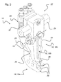
- FIG. 1 illustrates the construction of a gripper device 10 for detecting or gripping boxes 12, in which either beverage containers or bottles (not shown here) may be located.
- the boxes 12 are open at the top and each have lateral recesses 14.
- Fig. 1 shown several different sized boxes 12, which are in a regular arrangement, for example, on a pallet 50 or a similar support surface.
- the gripper device 10 has a plurality of pivotable gripper units 16, which are each provided with pivotable into the lateral recesses 14 of the boxes 12 gripper fingers 18, each hook-shaped ends 20 (see. Fig. 2 ) exhibit.
- each gripper unit 16 has three gripper fingers 18 with associated hook-shaped ends 20, which are arranged at different heights.
- the gripper device 10 is relatively tolerant to different box heights and / or sizes, dimensions and / or heights of their lateral recesses 14.
- Various boxes 12 with located at different heights recesses 14 can be handled easily with the help of engaging in different heights gripper fingers 18.
- the gripper fingers 18 of the gripper units 16 are each mounted in a base region 22 and pivotable independently of each other.
- the individual gripper fingers 18 are movably mounted about a common axis of rotation 28 in the base region 22, as shown in the Figures 2 and 3 is illustrated in detail.
- the independent storage allows engagement in different box recesses 14, wherein the respective matching gripper fingers 18 engages in the recess 14, while the other gripper fingers 18 and do not engage and dodge due to their pivotal storage and / or of the closed areas of the box walls 27 in an evasive movement can be forced.
- the gripping device 10 comprises at least two such arrangements, as in Fig. 1 are recognizable.
- the gripper device 10 comprises a total of several gripper units 16, with their base portions 22 each on a common Shaft 24 are stored.
- the shaft 24 is controlled and moved by a drive (not shown here). In the control of the shaft 24 rotates by a small pivot angle sufficient to move the gripper units 16 respectively to the boxes 12, as soon as they are to be picked up.
- a gripper finger 18 of the respective gripper unit 16 engages under a handle support surface 26 in the recess 14 of the boxes 12.
- the gripper device 10 comprises at least two gripper units 16, which are preferably each configured with at least two gripper fingers 18. These gripper units 16 are each arranged opposite, so that they can grab a box 12 from both sides. For this purpose, the hook-shaped ends 20 of each gripper unit 16 in one direction and the interaction of the two gripper units 16, the hook-shaped ends 20 are directed to the center of the box. As in Fig. 1 recognizable, the gripper device 10 has three or more gripper units 16 which are mounted on a common shaft 24, of which only one of the opposite pairs of gripper units 16 are drawn. However, there may also be four, five or more such pairs.
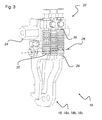
- FIG. 1 The schematic perspective views of Figures 2 and 3 show the structure of a gripper unit 16 of the gripper device 10 from Fig. 1 ,
- the gripper unit 16 shown here has a total of three gripper fingers 18 which are mounted together in the base region 22 and are pivotable independently of each other. Visible is still the fixed screwing of the base portion 22 on the hexagonal shaft 24.
- the gripper fingers 18 are on a common Rotary axis 28 movably mounted in the base region 22. So that the gripper fingers 18 can be mounted close to each other to save space, a first gripper finger 18a has a C-shaped contour with a recess 30, which forms a movement space for a second gripper finger 18b.
- the two gripper fingers 18a and 18b are aligned approximately in one plane and are pivotable in a common or approximately congruent plane of movement.
- a third gripper finger 18c is arranged next to the other two gripper fingers 18a and 18b and is pivotable in a movement plane parallel thereto.
- the gripper fingers 18a, 18b and 18c each have different lengths of leg 19, so that their hook-shaped gripper ends 20 are each arranged at different heights.
- the legs 19 of the gripper fingers 18 may be straight or cranked, as in Fig. 2 and 3 is indicated and are arranged approximately parallel to each other.
- the first gripper finger 18a and the third gripper finger 18c each have a crank, while the second gripper finger 18b is un-cranked, so that the hook-shaped ends 20 are very close to each other.
- the gripper fingers 18 can be relatively easily produced by punching and / or bending operations of a suitable sheet material.
- the gripper fingers 18 of each gripper unit 16 are each equipped with a return spring 32, wherein the restoring force of an evasive movement of the movably mounted gripper fingers 18 when hitting a side wall or box wall 27 of a box to be gripped 12 counteracts.
- An engaging in the box recess 14 gripper fingers 18 is pivoted by the restoring force of the spring 32 in the direction of its rest position, while the or the other gripper fingers 18 are biased stronger.
- only one gripper finger 18 is activated, which has the appropriate length of the leg 19 to pivot into the recess 14 of the respective box 12 and to grab this.
- a gripper finger 18, which is present at a box wall 27, is slightly pivoted by the restoring force about the axis of rotation 28 to the rear.
- the gripper fingers 18 each paragraphs 34 on their backs, as in Fig. 3 is clarified.
- the undersides of the springs 32 rests on these shoulders 34, while their tops are respectively supported in adjustable spring bearings 36 by means of screw connections are fixed in the base area 22.
- the restoring forces of the springs 32 for the individual gripper fingers 18 are each adjustable. This serves, for example, to provide the gripper fingers 18 of different lengths and thus engaging with different lever forces on the box 12 with an almost identical restoring force.
- the hooks 20 of the gripper fingers 18 each have a bearing surface 38 which engages the boxes 12 in their recesses 14.
- the bearing surfaces 38 can be, for example, corrugated, toothed and / or coated and / or provided with an anti-slip material.
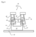
- FIG. 4 shows a schematic sectional view of a box 12, which stands for example on a pallet 50 and is detected and / or gripped by means of two gripper units 16.
- the hook-shaped ends 20 of the gripper fingers 18 have a bearing surface 38 which engages and lifts the box 12 in its recesses 14.
- the support surfaces 38 may preferably be corrugated and / or coated and / or have an anti-slip material (not shown).
- so-called centering fingers 40 can be used as an abutment of the spring-loaded gripper fingers 18 (cf. Fig. 2 and 3 ) serve.
- the centering fingers 40 are arranged on the opposite side of the box wall 27 and directly opposite the spring-loaded gripper fingers 18 such that they act to support, for example, yielding box walls 27, so that deformation of the box wall 27 is prevented.
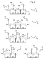
- FIG. 5 shows various arrangements of gripper units 16, which allow gripping and / or detecting boxes in a gripper device 10. These variants are not intended to be a conclusive list, as ultimately all conceivable arrangements of the gripper units 16 are possible.
- the number of boxes 12 is dependent on the number of gripper units 16 and how they are arranged in a gripper device 10 to each other. With an indicated double arrow, the pivotal movement of the respective pivotally mounted gripper units 16 should be displayed.
- the hook-shaped ends 20 pivot in the direction of the recess 14 (see. Fig. 1 or Fig. 4 ) of the boxes 12.
- the gripper units 16 are mounted on the shaft 24.
Landscapes
- Engineering & Computer Science (AREA)
- Mechanical Engineering (AREA)
- Manipulator (AREA)
- Load-Engaging Elements For Cranes (AREA)
- Wrapping Of Specific Fragile Articles (AREA)
- Specific Conveyance Elements (AREA)
Applications Claiming Priority (1)
| Application Number | Priority Date | Filing Date | Title |
|---|---|---|---|
| DE102009026361A DE102009026361A1 (de) | 2009-08-11 | 2009-08-11 | Greifervorrichtung zum gleichzeitigen Erfassen und/oder Greifen mehrerer Gebinde und/oder Kästen |
Publications (3)
| Publication Number | Publication Date |
|---|---|
| EP2284115A2 EP2284115A2 (de) | 2011-02-16 |
| EP2284115A3 EP2284115A3 (de) | 2011-10-12 |
| EP2284115B1 true EP2284115B1 (de) | 2015-06-24 |
Family
ID=43234207
Family Applications (1)
| Application Number | Title | Priority Date | Filing Date |
|---|---|---|---|
| EP10156778.2A Active EP2284115B1 (de) | 2009-08-11 | 2010-03-17 | Greifervorrichtung |
Country Status (4)
| Country | Link |
|---|---|
| US (1) | US8376433B2 (zh) |
| EP (1) | EP2284115B1 (zh) |
| CN (1) | CN101992946B (zh) |
| DE (1) | DE102009026361A1 (zh) |
Families Citing this family (14)
| Publication number | Priority date | Publication date | Assignee | Title |
|---|---|---|---|---|
| EP2575810A1 (en) | 2010-05-24 | 2013-04-10 | Synta Pharmaceuticals Corp. | Cancer therapy using a combination of a hsp90 inhibitory compound and a topoisomerase ii inhibitor |
| JP6136775B2 (ja) * | 2013-08-30 | 2017-05-31 | 株式会社ダイフク | 搬送装置 |
| DE102013112572B4 (de) * | 2013-11-14 | 2015-10-29 | Rattunde & Co. Gmbh | Zwillingsgreifer |
| CN103738836B (zh) * | 2013-12-23 | 2016-01-20 | 柳州正菱集团有限公司 | 一种发动机吊具 |
| DE102014000403A1 (de) * | 2014-01-17 | 2015-07-23 | Elementar Analysensysteme Gmbh | Anordnung umfassend einen Tiegel und eine Beschickungsvorrichtung |
| US9724831B2 (en) * | 2015-08-28 | 2017-08-08 | Te Connectivity Corporation | Robotic gripper mechanism |
| DE102015223627A1 (de) * | 2015-11-30 | 2017-06-01 | Renz GmbH & Co. KG | Halteelement und Baustoffgreiferanordnung mit einem solchen |
| CN105480718B (zh) * | 2016-01-16 | 2018-06-26 | 深圳市圣天达自动化科技有限公司 | 一种高效率自动led全彩大屏幕插装机构 |
| ITUA20162979A1 (it) | 2016-04-28 | 2017-10-28 | Illinois Tool Works | Teste per placcatura a nastro aventi limiti di pressione del nastro e sistemi di placcatura a nastro con teste per placcatura a nastro aventi limiti di pressione del nastro |
| ITUA20162977A1 (it) * | 2016-04-28 | 2017-10-28 | Illinois Tool Works | Alimentatori di nastro per placcatura aventi supporti di guida regolabili per il nastro e sistemi di placcatura a nastro con alimentatori di nastro per placcatura aventi supporti di guida regolabili per il nastro |
| ITUA20162975A1 (it) | 2016-04-28 | 2017-10-28 | Illinois Tool Works | Alimentatori di nastro per placcatura aventi rulli di pressione indipendenti e sistemi di placcatura a nastro con alimentatori di nastro per placcatura aventi rulli di pressione indipendenti |
| DE102018127974A1 (de) * | 2018-11-08 | 2020-05-14 | Kromberg & Schubert Gmbh & Co. Kg | Greifvorrichtung zum voneinander unabhängigen Greifen zweier Leiter |
| CN109848709B (zh) * | 2019-03-21 | 2023-09-26 | 深圳市联欣科技有限公司 | 数据线屏蔽壳对接铆压设备 |
| CN114873468B (zh) * | 2022-05-17 | 2023-05-30 | 山东大学 | 面向酿造环境的天车抓斗防碰撞方法及系统 |
Citations (3)
| Publication number | Priority date | Publication date | Assignee | Title |
|---|---|---|---|---|
| JPS5111575U (zh) * | 1974-07-16 | 1976-01-28 | ||
| JPS5187679A (ja) * | 1975-01-30 | 1976-07-31 | Motoda Denshi Kogyo Kk | Ryutaiatsushirindayunitsuto |
| JPH05132147A (ja) * | 1991-11-11 | 1993-05-28 | Nippon Steel Corp | 角管及び形鋼の段積み装置及び段積み方法 |
Family Cites Families (21)
| Publication number | Priority date | Publication date | Assignee | Title |
|---|---|---|---|---|
| DE7930603U1 (de) * | 1980-09-25 | Holstein Und Kappert Gmbh, 4600 Dortmund | Vorrichtung zum Signalisieren von Schaltpositionen an Verpackungsmaschinen | |
| US2879102A (en) * | 1951-06-11 | 1959-03-24 | Kughler Edwin Russell | Barrel lifting device |
| US3250229A (en) * | 1962-11-13 | 1966-05-10 | Kalamazoo Mfg Company | Tie and rail raising and tamping machine |
| DE2253185A1 (de) | 1972-10-30 | 1974-05-09 | Kettner Brauereimaschf | Greifervorrichtung zum gleichzeitigen erfassen mehrerer kaesten, insbesondere flaschenkaesten |
| DE2724978C2 (de) * | 1977-06-02 | 1985-04-04 | Schaefer Förderanlagen- und Maschinenbau GmbH, 8043 Unterföhring | Vorrichtung zum Aufeinandersetzen von Kästen |
| DE2735791C2 (de) | 1977-08-09 | 1984-02-23 | Seitz Enzinger Noll Maschinenbau Ag, 6800 Mannheim | Verfahrbarer Schichtengreifer für Flaschenkästen mit Erfassung durch Haken |
| DE2839473C2 (de) * | 1978-09-11 | 1984-05-10 | Seitz Enzinger Noll Maschinenbau Ag, 6800 Mannheim | Schichtengreifer für Flaschenkästen mit je einer Überlasteinrichtung für die verschwenkbaren Haken |
| DD145257A1 (de) | 1979-09-07 | 1980-12-03 | Harald Jesch | Greifer zum be-und entpalettieren von insbesondere flaschenkaestenlagen |
| DE7935243U1 (de) * | 1979-12-14 | 1981-08-27 | Holstein Und Kappert Gmbh, 4600 Dortmund | Vorrichtung zum umsetzen von mit ausnmehmungen ausgestatteten stueckguetern |
| DE3032805C1 (de) * | 1980-08-30 | 1982-06-16 | C. Keller GmbH u. Co KG, 4530 Ibbenbüren | Greifvorrichtung zum schichtweisen Abtragen von in Stapeln gebrannten Ziegelsteinen |
| DE3400957C1 (de) * | 1984-01-13 | 1984-10-18 | C. Keller GmbH u. Co KG, 4530 Ibbenbüren | Greifvorrichtung zum schichtweisen Abtragen von in Stapeln gebrannten Ziegelsteinen |
| US4632444A (en) * | 1985-05-03 | 1986-12-30 | Rca Corporation | Robot hand |
| JPH0726008U (ja) * | 1989-06-09 | 1995-05-16 | 日本鋼管株式会社 | リフター装置 |
| DE3940865C1 (zh) * | 1989-12-11 | 1991-04-25 | Steinle Maschinenfabrik Gmbh, 8900 Augsburg, De | |
| US5253912A (en) * | 1991-04-10 | 1993-10-19 | Axis Usa, Inc. | Gripper apparatus for electric motor components |
| DE4426615C1 (de) * | 1994-07-27 | 1995-09-14 | Ludwig Stiny | Vorrichtung zum Stapeln oder Entstapeln von stapelbarem Gut |
| DE29806424U1 (de) * | 1998-04-08 | 1999-08-05 | Keuro Besitz Gmbh & Co | Transportvorrichtung für Behältnisse zur Aufnahme von Material |
| DE19901496C1 (de) | 1999-01-11 | 2000-11-30 | Mannesmann Ag | Klemmgreifer für von oben zu greifende Lasten |
| US6412844B1 (en) * | 2000-01-14 | 2002-07-02 | Lockheed Martin Corporation | Robotic gripper mechanism |
| US8259752B2 (en) | 2004-05-07 | 2012-09-04 | Interdigital Technology Corporation | Medium access control layer architecture for supporting enhanced uplink |
| DE202005007347U1 (de) | 2005-05-04 | 2005-07-28 | Abb Patent Gmbh | Roboterwerkzeug zum Aufnehmen und Transportieren eines Behälters |
-
2009
- 2009-08-11 DE DE102009026361A patent/DE102009026361A1/de not_active Withdrawn
-
2010
- 2010-03-17 EP EP10156778.2A patent/EP2284115B1/de active Active
- 2010-06-01 CN CN201010191915.7A patent/CN101992946B/zh active Active
- 2010-06-15 US US12/815,806 patent/US8376433B2/en active Active
Patent Citations (3)
| Publication number | Priority date | Publication date | Assignee | Title |
|---|---|---|---|---|
| JPS5111575U (zh) * | 1974-07-16 | 1976-01-28 | ||
| JPS5187679A (ja) * | 1975-01-30 | 1976-07-31 | Motoda Denshi Kogyo Kk | Ryutaiatsushirindayunitsuto |
| JPH05132147A (ja) * | 1991-11-11 | 1993-05-28 | Nippon Steel Corp | 角管及び形鋼の段積み装置及び段積み方法 |
Also Published As
| Publication number | Publication date |
|---|---|
| EP2284115A2 (de) | 2011-02-16 |
| DE102009026361A1 (de) | 2011-02-17 |
| US20110037283A1 (en) | 2011-02-17 |
| CN101992946A (zh) | 2011-03-30 |
| US8376433B2 (en) | 2013-02-19 |
| CN101992946B (zh) | 2014-11-05 |
| EP2284115A3 (de) | 2011-10-12 |
Similar Documents
| Publication | Publication Date | Title |
|---|---|---|
| EP2284115B1 (de) | Greifervorrichtung | |
| EP1890954B2 (de) | Verfahren und vorrichtung zum entpalletieren von gestapelten gebinden | |
| EP0377398B1 (de) | Palettierroboter | |
| DE102015115866B4 (de) | Einrichtung zum Umpacken von zu Packungseinheiten zusammengefassten Stückgütern | |
| EP1698584B1 (de) | Flurförderzeug | |
| WO2007131464A1 (de) | Greifsystem für gestapeltes stückgut | |
| EP0482406A1 (de) | Vorrichtung zum Handhaben von Gegenständen, wie Kartons | |
| EP0377399A1 (de) | Greifvorrichtung | |
| DE102008039110A1 (de) | Greifervorrichtung zum gleichzeitigen Erfassen mehrerer Gebinde und/oder Kästen mit Getränkebehältern und Verfahren zur Justierung der Greifervorrichtung | |
| EP3037371B1 (de) | Vorrichtung und verfahren zur aufnahme, zum halten und/oder zur handhabung von flächigen gegenständen | |
| EP2218666B1 (de) | Verschwenkbare Begrenzungsleiste für auf einer Auflagefläche gruppierte Artikel | |
| EP2441712B1 (de) | Greiferkopf und Beladestation | |
| EP4112513A1 (de) | System mit einem greifer | |
| DE202005003077U1 (de) | Drehvorrichtung | |
| DE19834927A1 (de) | Verfahren und Vorrichtung zum Ein- und Auslagern von Stückgut | |
| EP3509973B1 (de) | Robotische transportvorrichtung zum transportieren von kleinteilen und mit der robotischen vorrichtung durchführbares verfahren | |
| DE3907332A1 (de) | Greifvorrichtung | |
| DE102010034992B4 (de) | Einrichtung zur Handhabung quaderförmiger Gegenstände | |
| DE102011005002B4 (de) | Wendeeinrichtung zum Wenden von, insbesondere palettierten, Lasten wie Platinenstapel oder vergleichbarer Pakete an Halbfertigteilen | |
| DE102012106140B4 (de) | Greifanordnung | |
| EP3421392A1 (de) | Regalbediengerät geeignet für den einsatz in einem hochregallager | |
| AT524051B1 (de) | Vorrichtung zum Verlagern von Transportbehältern zwischen einem Behälterstapel und einem Behälterregal | |
| DE102009040792A1 (de) | Palettenentstapler | |
| DE3507283C2 (zh) | ||
| DE19964034A1 (de) | Greifervorrichtung für einen Hublader |
Legal Events
| Date | Code | Title | Description |
|---|---|---|---|
| PUAI | Public reference made under article 153(3) epc to a published international application that has entered the european phase |
Free format text: ORIGINAL CODE: 0009012 |
|
| AK | Designated contracting states |
Kind code of ref document: A2 Designated state(s): AT BE BG CH CY CZ DE DK EE ES FI FR GB GR HR HU IE IS IT LI LT LU LV MC MK MT NL NO PL PT RO SE SI SK SM TR |
|
| AX | Request for extension of the european patent |
Extension state: AL BA ME RS |
|
| PUAL | Search report despatched |
Free format text: ORIGINAL CODE: 0009013 |
|
| AK | Designated contracting states |
Kind code of ref document: A3 Designated state(s): AT BE BG CH CY CZ DE DK EE ES FI FR GB GR HR HU IE IS IT LI LT LU LV MC MK MT NL NO PL PT RO SE SI SK SM TR |
|
| AX | Request for extension of the european patent |
Extension state: AL BA ME RS |
|
| RIC1 | Information provided on ipc code assigned before grant |
Ipc: B65G 47/90 20060101ALI20110905BHEP Ipc: B65B 35/36 20060101ALI20110905BHEP Ipc: B66C 1/28 20060101AFI20110905BHEP |
|
| 17P | Request for examination filed |
Effective date: 20111208 |
|
| RIN1 | Information on inventor provided before grant (corrected) |
Inventor name: KIRSCHNER, PETER Inventor name: WEGENER, KAI Inventor name: BAIER, ALEXANDER |
|
| 17Q | First examination report despatched |
Effective date: 20141014 |
|
| GRAP | Despatch of communication of intention to grant a patent |
Free format text: ORIGINAL CODE: EPIDOSNIGR1 |
|
| INTG | Intention to grant announced |
Effective date: 20150311 |
|
| RIN1 | Information on inventor provided before grant (corrected) |
Inventor name: WEGENER, KAI Inventor name: BAIER, ALEXANDER Inventor name: KIRSCHNER, PETER |
|
| GRAS | Grant fee paid |
Free format text: ORIGINAL CODE: EPIDOSNIGR3 |
|
| GRAA | (expected) grant |
Free format text: ORIGINAL CODE: 0009210 |
|
| AK | Designated contracting states |
Kind code of ref document: B1 Designated state(s): AT BE BG CH CY CZ DE DK EE ES FI FR GB GR HR HU IE IS IT LI LT LU LV MC MK MT NL NO PL PT RO SE SI SK SM TR |
|
| REG | Reference to a national code |
Ref country code: GB Ref legal event code: FG4D Free format text: NOT ENGLISH |
|
| REG | Reference to a national code |
Ref country code: CH Ref legal event code: EP |
|
| REG | Reference to a national code |
Ref country code: AT Ref legal event code: REF Ref document number: 732790 Country of ref document: AT Kind code of ref document: T Effective date: 20150715 |
|
| REG | Reference to a national code |
Ref country code: IE Ref legal event code: FG4D Free format text: LANGUAGE OF EP DOCUMENT: GERMAN |
|
| REG | Reference to a national code |
Ref country code: DE Ref legal event code: R096 Ref document number: 502010009720 Country of ref document: DE |
|
| PG25 | Lapsed in a contracting state [announced via postgrant information from national office to epo] |
Ref country code: FI Free format text: LAPSE BECAUSE OF FAILURE TO SUBMIT A TRANSLATION OF THE DESCRIPTION OR TO PAY THE FEE WITHIN THE PRESCRIBED TIME-LIMIT Effective date: 20150624 Ref country code: NO Free format text: LAPSE BECAUSE OF FAILURE TO SUBMIT A TRANSLATION OF THE DESCRIPTION OR TO PAY THE FEE WITHIN THE PRESCRIBED TIME-LIMIT Effective date: 20150924 Ref country code: LT Free format text: LAPSE BECAUSE OF FAILURE TO SUBMIT A TRANSLATION OF THE DESCRIPTION OR TO PAY THE FEE WITHIN THE PRESCRIBED TIME-LIMIT Effective date: 20150624 Ref country code: HR Free format text: LAPSE BECAUSE OF FAILURE TO SUBMIT A TRANSLATION OF THE DESCRIPTION OR TO PAY THE FEE WITHIN THE PRESCRIBED TIME-LIMIT Effective date: 20150624 |
|
| REG | Reference to a national code |
Ref country code: LT Ref legal event code: MG4D |
|
| PG25 | Lapsed in a contracting state [announced via postgrant information from national office to epo] |
Ref country code: LV Free format text: LAPSE BECAUSE OF FAILURE TO SUBMIT A TRANSLATION OF THE DESCRIPTION OR TO PAY THE FEE WITHIN THE PRESCRIBED TIME-LIMIT Effective date: 20150624 Ref country code: GR Free format text: LAPSE BECAUSE OF FAILURE TO SUBMIT A TRANSLATION OF THE DESCRIPTION OR TO PAY THE FEE WITHIN THE PRESCRIBED TIME-LIMIT Effective date: 20150925 Ref country code: BG Free format text: LAPSE BECAUSE OF FAILURE TO SUBMIT A TRANSLATION OF THE DESCRIPTION OR TO PAY THE FEE WITHIN THE PRESCRIBED TIME-LIMIT Effective date: 20150924 |
|
| REG | Reference to a national code |
Ref country code: NL Ref legal event code: MP Effective date: 20150624 |
|
| PG25 | Lapsed in a contracting state [announced via postgrant information from national office to epo] |
Ref country code: EE Free format text: LAPSE BECAUSE OF FAILURE TO SUBMIT A TRANSLATION OF THE DESCRIPTION OR TO PAY THE FEE WITHIN THE PRESCRIBED TIME-LIMIT Effective date: 20150624 |
|
| REG | Reference to a national code |
Ref country code: FR Ref legal event code: PLFP Year of fee payment: 7 |
|
| PG25 | Lapsed in a contracting state [announced via postgrant information from national office to epo] |
Ref country code: PT Free format text: LAPSE BECAUSE OF FAILURE TO SUBMIT A TRANSLATION OF THE DESCRIPTION OR TO PAY THE FEE WITHIN THE PRESCRIBED TIME-LIMIT Effective date: 20151026 Ref country code: SK Free format text: LAPSE BECAUSE OF FAILURE TO SUBMIT A TRANSLATION OF THE DESCRIPTION OR TO PAY THE FEE WITHIN THE PRESCRIBED TIME-LIMIT Effective date: 20150624 Ref country code: ES Free format text: LAPSE BECAUSE OF FAILURE TO SUBMIT A TRANSLATION OF THE DESCRIPTION OR TO PAY THE FEE WITHIN THE PRESCRIBED TIME-LIMIT Effective date: 20150624 Ref country code: IS Free format text: LAPSE BECAUSE OF FAILURE TO SUBMIT A TRANSLATION OF THE DESCRIPTION OR TO PAY THE FEE WITHIN THE PRESCRIBED TIME-LIMIT Effective date: 20151024 Ref country code: CZ Free format text: LAPSE BECAUSE OF FAILURE TO SUBMIT A TRANSLATION OF THE DESCRIPTION OR TO PAY THE FEE WITHIN THE PRESCRIBED TIME-LIMIT Effective date: 20150624 Ref country code: RO Free format text: LAPSE BECAUSE OF NON-PAYMENT OF DUE FEES Effective date: 20150624 Ref country code: PL Free format text: LAPSE BECAUSE OF FAILURE TO SUBMIT A TRANSLATION OF THE DESCRIPTION OR TO PAY THE FEE WITHIN THE PRESCRIBED TIME-LIMIT Effective date: 20150624 |
|
| REG | Reference to a national code |
Ref country code: DE Ref legal event code: R097 Ref document number: 502010009720 Country of ref document: DE |
|
| PG25 | Lapsed in a contracting state [announced via postgrant information from national office to epo] |
Ref country code: DK Free format text: LAPSE BECAUSE OF FAILURE TO SUBMIT A TRANSLATION OF THE DESCRIPTION OR TO PAY THE FEE WITHIN THE PRESCRIBED TIME-LIMIT Effective date: 20150624 |
|
| PLBE | No opposition filed within time limit |
Free format text: ORIGINAL CODE: 0009261 |
|
| STAA | Information on the status of an ep patent application or granted ep patent |
Free format text: STATUS: NO OPPOSITION FILED WITHIN TIME LIMIT |
|
| 26N | No opposition filed |
Effective date: 20160329 |
|
| PG25 | Lapsed in a contracting state [announced via postgrant information from national office to epo] |
Ref country code: SI Free format text: LAPSE BECAUSE OF FAILURE TO SUBMIT A TRANSLATION OF THE DESCRIPTION OR TO PAY THE FEE WITHIN THE PRESCRIBED TIME-LIMIT Effective date: 20150624 Ref country code: BE Free format text: LAPSE BECAUSE OF NON-PAYMENT OF DUE FEES Effective date: 20160331 |
|
| PG25 | Lapsed in a contracting state [announced via postgrant information from national office to epo] |
Ref country code: LU Free format text: LAPSE BECAUSE OF FAILURE TO SUBMIT A TRANSLATION OF THE DESCRIPTION OR TO PAY THE FEE WITHIN THE PRESCRIBED TIME-LIMIT Effective date: 20160317 Ref country code: MC Free format text: LAPSE BECAUSE OF FAILURE TO SUBMIT A TRANSLATION OF THE DESCRIPTION OR TO PAY THE FEE WITHIN THE PRESCRIBED TIME-LIMIT Effective date: 20150624 |
|
| REG | Reference to a national code |
Ref country code: CH Ref legal event code: PL |
|
| GBPC | Gb: european patent ceased through non-payment of renewal fee |
Effective date: 20160317 |
|
| REG | Reference to a national code |
Ref country code: IE Ref legal event code: MM4A |
|
| PG25 | Lapsed in a contracting state [announced via postgrant information from national office to epo] |
Ref country code: IE Free format text: LAPSE BECAUSE OF NON-PAYMENT OF DUE FEES Effective date: 20160317 Ref country code: CH Free format text: LAPSE BECAUSE OF NON-PAYMENT OF DUE FEES Effective date: 20160331 Ref country code: LI Free format text: LAPSE BECAUSE OF NON-PAYMENT OF DUE FEES Effective date: 20160331 Ref country code: GB Free format text: LAPSE BECAUSE OF NON-PAYMENT OF DUE FEES Effective date: 20160317 |
|
| REG | Reference to a national code |
Ref country code: FR Ref legal event code: PLFP Year of fee payment: 8 |
|
| REG | Reference to a national code |
Ref country code: AT Ref legal event code: MM01 Ref document number: 732790 Country of ref document: AT Kind code of ref document: T Effective date: 20160317 |
|
| PG25 | Lapsed in a contracting state [announced via postgrant information from national office to epo] |
Ref country code: SE Free format text: LAPSE BECAUSE OF FAILURE TO SUBMIT A TRANSLATION OF THE DESCRIPTION OR TO PAY THE FEE WITHIN THE PRESCRIBED TIME-LIMIT Effective date: 20150624 Ref country code: NL Free format text: LAPSE BECAUSE OF FAILURE TO SUBMIT A TRANSLATION OF THE DESCRIPTION OR TO PAY THE FEE WITHIN THE PRESCRIBED TIME-LIMIT Effective date: 20150624 |
|
| PG25 | Lapsed in a contracting state [announced via postgrant information from national office to epo] |
Ref country code: AT Free format text: LAPSE BECAUSE OF NON-PAYMENT OF DUE FEES Effective date: 20160317 Ref country code: MT Free format text: LAPSE BECAUSE OF FAILURE TO SUBMIT A TRANSLATION OF THE DESCRIPTION OR TO PAY THE FEE WITHIN THE PRESCRIBED TIME-LIMIT Effective date: 20150624 |
|
| REG | Reference to a national code |
Ref country code: FR Ref legal event code: PLFP Year of fee payment: 9 |
|
| PG25 | Lapsed in a contracting state [announced via postgrant information from national office to epo] |
Ref country code: HU Free format text: LAPSE BECAUSE OF FAILURE TO SUBMIT A TRANSLATION OF THE DESCRIPTION OR TO PAY THE FEE WITHIN THE PRESCRIBED TIME-LIMIT; INVALID AB INITIO Effective date: 20100317 Ref country code: CY Free format text: LAPSE BECAUSE OF FAILURE TO SUBMIT A TRANSLATION OF THE DESCRIPTION OR TO PAY THE FEE WITHIN THE PRESCRIBED TIME-LIMIT Effective date: 20150624 Ref country code: SM Free format text: LAPSE BECAUSE OF FAILURE TO SUBMIT A TRANSLATION OF THE DESCRIPTION OR TO PAY THE FEE WITHIN THE PRESCRIBED TIME-LIMIT Effective date: 20150624 |
|
| PG25 | Lapsed in a contracting state [announced via postgrant information from national office to epo] |
Ref country code: MK Free format text: LAPSE BECAUSE OF FAILURE TO SUBMIT A TRANSLATION OF THE DESCRIPTION OR TO PAY THE FEE WITHIN THE PRESCRIBED TIME-LIMIT Effective date: 20150624 Ref country code: TR Free format text: LAPSE BECAUSE OF FAILURE TO SUBMIT A TRANSLATION OF THE DESCRIPTION OR TO PAY THE FEE WITHIN THE PRESCRIBED TIME-LIMIT Effective date: 20150624 |
|
| PGFP | Annual fee paid to national office [announced via postgrant information from national office to epo] |
Ref country code: FR Payment date: 20230208 Year of fee payment: 14 |
|
| PGFP | Annual fee paid to national office [announced via postgrant information from national office to epo] |
Ref country code: IT Payment date: 20230213 Year of fee payment: 14 |
|
| P01 | Opt-out of the competence of the unified patent court (upc) registered |
Effective date: 20230523 |
|
| PGFP | Annual fee paid to national office [announced via postgrant information from national office to epo] |
Ref country code: DE Payment date: 20240130 Year of fee payment: 15 |