EP2283984A2 - Procédé et dispositif pour la découpe de troncs d'arbre - Google Patents
Procédé et dispositif pour la découpe de troncs d'arbre Download PDFInfo
- Publication number
- EP2283984A2 EP2283984A2 EP20100008318 EP10008318A EP2283984A2 EP 2283984 A2 EP2283984 A2 EP 2283984A2 EP 20100008318 EP20100008318 EP 20100008318 EP 10008318 A EP10008318 A EP 10008318A EP 2283984 A2 EP2283984 A2 EP 2283984A2
- Authority
- EP
- European Patent Office
- Prior art keywords
- tree trunk
- band saw
- devices
- cutting
- along
- Prior art date
- Legal status (The legal status is an assumption and is not a legal conclusion. Google has not performed a legal analysis and makes no representation as to the accuracy of the status listed.)
- Withdrawn
Links
Images


Classifications
-
- B—PERFORMING OPERATIONS; TRANSPORTING
- B27—WORKING OR PRESERVING WOOD OR SIMILAR MATERIAL; NAILING OR STAPLING MACHINES IN GENERAL
- B27B—SAWS FOR WOOD OR SIMILAR MATERIAL; COMPONENTS OR ACCESSORIES THEREFOR
- B27B1/00—Methods for subdividing trunks or logs essentially involving sawing
- B27B1/005—Methods for subdividing trunks or logs essentially involving sawing including the step of dividing the log into sector-shaped segments
-
- B—PERFORMING OPERATIONS; TRANSPORTING
- B27—WORKING OR PRESERVING WOOD OR SIMILAR MATERIAL; NAILING OR STAPLING MACHINES IN GENERAL
- B27B—SAWS FOR WOOD OR SIMILAR MATERIAL; COMPONENTS OR ACCESSORIES THEREFOR
- B27B15/00—Band or strap sawing machines specially designed for length cutting of trunks
- B27B15/08—Band or strap sawing machines specially designed for length cutting of trunks with a plurality of band saw blades
Definitions
- the present invention relates to a method and apparatus for cutting tree trunks, in particular small trees.
- From the DE 10 2004 052 130 B3 shows a sawing, with the help of which in the longitudinal direction of a tree trunk extending saw cuts can be performed.
- a bearing surface on which rests the tree trunk, and a stop bracket attached thereto, against which the tree trunk, are pivoted together about an axis with respect to the cutting plane of the sawing device.
- the object of the present invention is to provide a method for cutting tree trunks, in particular small logs, in such a way that a relatively high yield of boards is made possible, while at the same time the quality of the boards produced is substantially improved. Furthermore, a device suitable for carrying out this method should be provided.
- This object is achieved by a method for cutting logs, in particular small logs, in which a plurality of bandsaw devices are arranged in front of one side of a tree trunk to be cut to produce individual segment boards so as to produce cuts in the tree trunk whose cut planes are in the circumferential direction of the tree trunk spaced apart and each along a diameter of the tree trunk and in the longitudinal direction thereof.
- the main advantage of the present method for cutting small logs is that a very high timber yield in the form of boards can be achieved. While a yield of boards of 45 to 50% can be achieved with previously known processes, a yield of 87 to 91% can be achieved with the process according to the invention. This means at the same time that the device according to the invention can be used much better and more effectively, which is associated with a cost saving.
- Another important advantage of the present invention is that the quality of the boards produced is comparatively large, since the boards have essentially only "standing annual rings".
- the cuts are particularly preferably introduced so that the corresponding cutting planes are evenly spaced from each other. This is advantageous with regard to the further processing of the generated segment boards.
- the band saw assemblies are stationary on one side of the trunks to be trimmed and spaced along an extension of the longitudinal axis of the trunks, the trunks being moved towards the band saw assemblies to produce the trimming planes. It has proven to be particularly advantageous if six bandsaw devices are provided for the production of twelve segment boards.
- engaging regions of holding parts can be inserted into the already generated regions of the cuts from the circumference of the tree trunk in one end region of the tree trunk.
- the holding parts are each introduced so that an engagement area in the generated area of a section engages a predetermined distance radially and a contact area rests on the circumference of the tree trunk.
- a clamp part can be annularly placed, which clasps and holds together the holding parts, so that the tree trunk can be grasped and moved by grasping the clamp part behind the band sawing devices.
- two radially opposing segment boards are expediently placed against each other along a cutting plane and fastened to one another in such a way that a board having an approximately rectangular cross-section results.
- the two segment boards are expediently simply glued to one another at the cutting planes.
- each band saw device sawing devices with which prior to cutting the associated band saw device in the diametrically opposite outer or bark areas of the band saw Tree trunk in the longitudinal direction of the same and in the subsequent cutting plane of each associated band saw means longitudinal grooves are generated, which extend to a predetermined depth in the outer or bark area of the tree trunk to remove said contaminants.
- the outer or bark areas of the individual segment boards can be removed in each case with the help of a gap part, which is driven into a segment board along an outer ring of the year.
- An apparatus for achieving the object according to the invention comprises a plurality of band saw devices, which are arranged such that their respective cutting planes to be produced in a tree trunk along a diameter of the tree trunk and in the longitudinal direction thereof are spaced apart in the circumferential direction of the tree trunk.
- the band saw devices are arranged relative to one another such that the cutting planes of the cuts made by them are equally spaced in the circumferential direction of the log.
- the band saw devices are expediently spaced apart on one side of the tree trunks to be cut along an extension of the longitudinal axis thereof.
- the band saw devices preferably each comprise a band saw blade which is guided around outside of a tree trunk to be divided trunking guide rollers.
- the holding parts each having an engagement region and an abutment region angled relative to the engagement region.
- the engagement region is radially introduced into a generated region of a section a predetermined distance until the abutment region bears against the circumference of the tree trunk.
- a clamp member is placed annularly around the abutment areas of all introduced holding parts, so that it firmly grips the holding parts and can be taken to move the clasped tree trunk.
- each band saw device may be associated with a sawing device which is diametrically opposed to the section of the associated band saw device in the outer layer of the log and in the longitudinal direction thereof in the cutting plane of the associated band saw device opposite sides each produces a longitudinal groove which extends into the outer layer of the tree trunk to a predetermined depth.
- the sawing device preferably has the form of a circular saw, the circular saw blade in the direction of the band saw blade of the associated band saw device for introducing the longitudinal grooves is adjustable or movable.
- wedge-shaped split parts For easy removal of the outer regions of the individual segmental board preferably wedge-shaped split parts can be used, which can be driven into a segment board along an outer ring of the year.
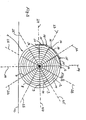
- FIG. 1 the cross-section of a tree trunk 1 to be disassembled or sawed by the method according to the invention is shown.
- the annual rings of the tree trunk 1 are denoted by 2 and the marrow thereof by 3.
- the tree trunk 1 is preferably a small log trunk, this term being understood to mean logs whose diameter is approximately 15 to 35 cm.
- FIG. 2 shows that the tree trunk 1, starting from its larger diameter (left side) to its smaller diameter (right side) tapers conically, wherein the annual rings 2 parallel to the outer edges 4, 5, ie thus with respect to the longitudinal axis 33 of the tree trunk. 1 also tapered.
- the band saw blade 15 of a band saw device 14 for producing the sectional plane 6 shown is shown.
- the saw teeth of the band saw blade 15 are designated 16.
- the band saw blade 15 extends over the guide rollers 17 and 18, of which at least one may be formed as a drive roller.
- the guide roller 18 is driven in the direction of the arrow 19 so that the band saw blade 15 moves in the direction of the arrow 20.
- the log 1 is moved in the feed direction 34.
- the band saw blade 14 generates the cutting plane 6 in the tree trunk 1 FIG. 3 are arranged.
- the individual Bandäg drivingen 14 to 26 are in the from the Figures 3 and 5 apparent manner in the circumferential direction of the Tree trunk 1 preferably evenly spaced from each other and also arranged side by side along a lateral extension of the longitudinal axis 33 of the tree trunk 1 and expediently evenly apart.
- FIG. 3 be produced with the help of only schematically illustrated by broken bands 14, 22, 23, 24, 25, 26, the cutting planes 6 to 11 extending radially through the medulla 3, such that a total of twelve wedge-shaped segment boards 13 are cut out of the tree trunk 1 of which one in the FIG. 4 is shown. It can be seen that each segmental board 13 essentially has only standing annual rings 2.
- this is on a support surface 12 ( FIG. 3 ), for example, the bearing surface of a block carriage, fixed tree trunk 1 in the direction of arrow 21 (FIG. FIG. 5 ) is moved to the band saw devices 14, 22, 23, 24, 25 and 26.
- the sections of the cutting planes 6, 7, 8, 9, 10, and 11 are generated, each extending along a defined by the arrangement of the respective band saw blade 15 diameter of the log 1 through the marrow 3 thereof.
- each bandsaw blade 15 of the bandsaw devices 14, 22, 23, 24, 25, 26 at the diametrically opposite sides the tree trunk 1 a sawing device 28 is provided, which preferably has a circular saw blade 29 and on the axis of rotation 30 of the same arranged on opposite sides of the circular saw blade 29 spacer rollers 31 whose diameter is smaller than the diameter of the circular saw blade 29.
- a sawing device 28 is particularly in the FIG. 6 shown.
- the sawing devices are movable in the direction of the arrows 19, such that their circular saw blades 29 engage in the diametrically opposite bark or peripheral regions of the tree trunk 1 moved in the direction of the arrow 21.
- the circular saw blades 29 are movable so far until the spacer rollers 31 abut the outer circumference of the tree trunk 1.
- the longitudinal grooves 39 are in each case produced exactly in front of the individual sections of the band saw blades 15 of the band saw devices 14, 22, 23, 24, 25, 26, so that any contamination of the circumferential or bark areas in the region of the longitudinal grooves 39 are eliminated. Damage and / or unwanted displacements of the band saw blades 15 are thereby avoided.
- the depth of the longitudinal grooves 39 corresponds to the difference between the radii of the spacer rollers 31 and the circular saw blade 29.
- the sawing devices 28 are automatically moved so that the spacer rollers 31 always abut the outer circumference of the tree trunk 1.
- FIG. 4 can be removed that the outer bark area of the individual segment boards 13 can be particularly easily removed by at least one appropriately wedge-shaped gap part 40 along an outer annual ring 2 from one side in the direction of the arrow 41 is driven into the segment board 13. Elaborate Schwarzen or the like are therefore not required.
Landscapes
- Life Sciences & Earth Sciences (AREA)
- Engineering & Computer Science (AREA)
- Mechanical Engineering (AREA)
- Wood Science & Technology (AREA)
- Forests & Forestry (AREA)
- Sawing (AREA)
- Debarking, Splitting, And Disintegration Of Timber (AREA)
Applications Claiming Priority (1)
| Application Number | Priority Date | Filing Date | Title |
|---|---|---|---|
| DE200910036931 DE102009036931A1 (de) | 2009-08-11 | 2009-08-11 | Verfahren und Vorrichtung zum Zerlegen von Schwachholz |
Publications (1)
| Publication Number | Publication Date |
|---|---|
| EP2283984A2 true EP2283984A2 (fr) | 2011-02-16 |
Family
ID=43063380
Family Applications (1)
| Application Number | Title | Priority Date | Filing Date |
|---|---|---|---|
| EP20100008318 Withdrawn EP2283984A2 (fr) | 2009-08-11 | 2010-08-10 | Procédé et dispositif pour la découpe de troncs d'arbre |
Country Status (2)
| Country | Link |
|---|---|
| EP (1) | EP2283984A2 (fr) |
| DE (1) | DE102009036931A1 (fr) |
Citations (1)
| Publication number | Priority date | Publication date | Assignee | Title |
|---|---|---|---|---|
| DE102004052130B3 (de) | 2004-10-27 | 2006-01-19 | Wassmer, Paul | Sägevorrichtung mit Auflagefläche für Baumstämme und mit einer quer zu dieser an einer Führung verstellbaren Anschlagkonsole |
-
2009
- 2009-08-11 DE DE200910036931 patent/DE102009036931A1/de not_active Withdrawn
-
2010
- 2010-08-10 EP EP20100008318 patent/EP2283984A2/fr not_active Withdrawn
Patent Citations (1)
| Publication number | Priority date | Publication date | Assignee | Title |
|---|---|---|---|---|
| DE102004052130B3 (de) | 2004-10-27 | 2006-01-19 | Wassmer, Paul | Sägevorrichtung mit Auflagefläche für Baumstämme und mit einer quer zu dieser an einer Führung verstellbaren Anschlagkonsole |
Also Published As
| Publication number | Publication date |
|---|---|
| DE102009036931A1 (de) | 2011-07-21 |
Similar Documents
| Publication | Publication Date | Title |
|---|---|---|
| DE102010018284A1 (de) | Turbinenschaufelrohling sowie Verfahren und Vorrichtung zum Bearbeiten eines Turbinenschaufelrohlings | |
| CH640770A5 (de) | Verfahren und vorrichtung zur spanenden zerlegung von baumstaemmen in allseitig bearbeitete holzerzeugnisse, wie bretter oder kantholz. | |
| DE3702890C2 (fr) | ||
| DE2605987B2 (de) | Verfahren und Vorrichtung zum Sägen von Holzstämmen | |
| EP0963822B1 (fr) | Dispositif et procédé pour le sciage des troncs d'arbres | |
| DE3534127A1 (de) | Verfahren und vorrichtung zum abtrennen von profilwerkstoff | |
| EP2810754B1 (fr) | Procédé et dispositif destiné au traitement d'un tronc d'arbre | |
| DE102009014861A1 (de) | Verfahren zur kontinuierlichen und vollständigen Zerlegung eines Baumstammes sowie Zerlegevorrichtung für Baumstämme zur Anwendung dieses Verfahrens | |
| EP2390035B1 (fr) | Utilisation d'une scie manuelle à fil pour le sciage d'une pièce en matériau isolant, en fibre douce ou en styropor | |
| DE3020321A1 (de) | Verfahren und vorrichtung zur spanenden zerlegung von baumstaemmen in hauptware und seitenbretter | |
| DE69527138T2 (de) | Rasierklingenherstellung | |
| DE19936312A1 (de) | Verfahren zum Zerteilen eines Naturrohstoffkörpers | |
| EP2283984A2 (fr) | Procédé et dispositif pour la découpe de troncs d'arbre | |
| DE4016628A1 (de) | Verfahren zum erzeugen von nutzholz aus baumstaemmen oder modeln, und vorrichtung zum durchfuehren des verfahrens | |
| DE102017120292A1 (de) | Trennvorrichtung für Rohre | |
| DE102007003945B3 (de) | Brennholzsäge- und Brennholzspaltvorrichtung sowie Verfahren zum Sägen und Spalten von Baumstämmen | |
| DE69612600T2 (de) | Verfahren zum spanabhebenden Bearbeiten von Baumstämmen | |
| EP2193894A1 (fr) | Procédé de sciage d'au moins une plaque | |
| EP1652640B1 (fr) | Dispositif de sciage pour des troncs d'arbres avec une surface de support et une surface de butée ajustable | |
| EP1050386A1 (fr) | Procédé et dispositif de transformation des bois ronds en planches | |
| DE202011051518U1 (de) | Vorrichtung zur Herstellung von Keilbohlen | |
| WO2019057658A1 (fr) | Procédé d'usinage de pièces, produit programme-informatique, et installation d'usinage de pièces | |
| EP1203645B1 (fr) | Procédé et dispositf pour le sciage des troncs d'arbres | |
| DE102004009222B4 (de) | Multifunktions-Schneidevorrichtung | |
| DE3504257C2 (de) | Gerät zum Abschneiden von Ästen, Bäumchen und Sträuchern |
Legal Events
| Date | Code | Title | Description |
|---|---|---|---|
| PUAI | Public reference made under article 153(3) epc to a published international application that has entered the european phase |
Free format text: ORIGINAL CODE: 0009012 |
|
| AK | Designated contracting states |
Kind code of ref document: A2 Designated state(s): AL AT BE BG CH CY CZ DE DK EE ES FI FR GB GR HR HU IE IS IT LI LT LU LV MC MK MT NL NO PL PT RO SE SI SK SM TR |
|
| AX | Request for extension of the european patent |
Extension state: BA ME RS |
|
| STAA | Information on the status of an ep patent application or granted ep patent |
Free format text: STATUS: THE APPLICATION IS DEEMED TO BE WITHDRAWN |
|
| 18D | Application deemed to be withdrawn |
Effective date: 20140301 |