EP2282237A2 - Bildpositionserkennungsvorrichtung und Bilderzeugungsvorrichtung dafür - Google Patents
Bildpositionserkennungsvorrichtung und Bilderzeugungsvorrichtung dafür Download PDFInfo
- Publication number
- EP2282237A2 EP2282237A2 EP10170068A EP10170068A EP2282237A2 EP 2282237 A2 EP2282237 A2 EP 2282237A2 EP 10170068 A EP10170068 A EP 10170068A EP 10170068 A EP10170068 A EP 10170068A EP 2282237 A2 EP2282237 A2 EP 2282237A2
- Authority
- EP
- European Patent Office
- Prior art keywords
- light
- photodetector
- light receiving
- detecting device
- position detecting
- Prior art date
- Legal status (The legal status is an assumption and is not a legal conclusion. Google has not performed a legal analysis and makes no representation as to the accuracy of the status listed.)
- Withdrawn
Links
- 230000001678 irradiating effect Effects 0.000 claims abstract description 56
- 230000003287 optical effect Effects 0.000 claims description 53
- 238000012634 optical imaging Methods 0.000 claims description 15
- 239000000758 substrate Substances 0.000 claims description 10
- 238000012546 transfer Methods 0.000 description 54
- 238000000034 method Methods 0.000 description 22
- 239000000463 material Substances 0.000 description 18
- 238000001514 detection method Methods 0.000 description 16
- 230000008569 process Effects 0.000 description 15
- 230000035945 sensitivity Effects 0.000 description 10
- 230000000052 comparative effect Effects 0.000 description 8
- 230000032258 transport Effects 0.000 description 8
- 238000012937 correction Methods 0.000 description 5
- 230000003247 decreasing effect Effects 0.000 description 5
- 239000003086 colorant Substances 0.000 description 4
- 238000004140 cleaning Methods 0.000 description 3
- 230000007246 mechanism Effects 0.000 description 3
- 230000008859 change Effects 0.000 description 2
- 238000002310 reflectometry Methods 0.000 description 2
- 238000012360 testing method Methods 0.000 description 2
- 238000011144 upstream manufacturing Methods 0.000 description 2
- 238000012935 Averaging Methods 0.000 description 1
- 238000012986 modification Methods 0.000 description 1
- 230000004048 modification Effects 0.000 description 1
- 229920001721 polyimide Polymers 0.000 description 1
- 239000009719 polyimide resin Substances 0.000 description 1
- 230000004043 responsiveness Effects 0.000 description 1
- 238000000926 separation method Methods 0.000 description 1
Images


Classifications
-
- G—PHYSICS
- G03—PHOTOGRAPHY; CINEMATOGRAPHY; ANALOGOUS TECHNIQUES USING WAVES OTHER THAN OPTICAL WAVES; ELECTROGRAPHY; HOLOGRAPHY
- G03G—ELECTROGRAPHY; ELECTROPHOTOGRAPHY; MAGNETOGRAPHY
- G03G15/00—Apparatus for electrographic processes using a charge pattern
- G03G15/01—Apparatus for electrographic processes using a charge pattern for producing multicoloured copies
- G03G15/0105—Details of unit
- G03G15/0131—Details of unit for transferring a pattern to a second base
-
- G—PHYSICS
- G03—PHOTOGRAPHY; CINEMATOGRAPHY; ANALOGOUS TECHNIQUES USING WAVES OTHER THAN OPTICAL WAVES; ELECTROGRAPHY; HOLOGRAPHY
- G03G—ELECTROGRAPHY; ELECTROPHOTOGRAPHY; MAGNETOGRAPHY
- G03G15/00—Apparatus for electrographic processes using a charge pattern
- G03G15/50—Machine control of apparatus for electrographic processes using a charge pattern, e.g. regulating differents parts of the machine, multimode copiers, microprocessor control
- G03G15/5054—Machine control of apparatus for electrographic processes using a charge pattern, e.g. regulating differents parts of the machine, multimode copiers, microprocessor control by measuring the characteristics of an intermediate image carrying member or the characteristics of an image on an intermediate image carrying member, e.g. intermediate transfer belt or drum, conveyor belt
- G03G15/5058—Machine control of apparatus for electrographic processes using a charge pattern, e.g. regulating differents parts of the machine, multimode copiers, microprocessor control by measuring the characteristics of an intermediate image carrying member or the characteristics of an image on an intermediate image carrying member, e.g. intermediate transfer belt or drum, conveyor belt using a test patch
-
- G—PHYSICS
- G03—PHOTOGRAPHY; CINEMATOGRAPHY; ANALOGOUS TECHNIQUES USING WAVES OTHER THAN OPTICAL WAVES; ELECTROGRAPHY; HOLOGRAPHY
- G03G—ELECTROGRAPHY; ELECTROPHOTOGRAPHY; MAGNETOGRAPHY
- G03G2215/00—Apparatus for electrophotographic processes
- G03G2215/00025—Machine control, e.g. regulating different parts of the machine
- G03G2215/00029—Image density detection
- G03G2215/00059—Image density detection on intermediate image carrying member, e.g. transfer belt
-
- G—PHYSICS
- G03—PHOTOGRAPHY; CINEMATOGRAPHY; ANALOGOUS TECHNIQUES USING WAVES OTHER THAN OPTICAL WAVES; ELECTROGRAPHY; HOLOGRAPHY
- G03G—ELECTROGRAPHY; ELECTROPHOTOGRAPHY; MAGNETOGRAPHY
- G03G2215/00—Apparatus for electrophotographic processes
- G03G2215/00362—Apparatus for electrophotographic processes relating to the copy medium handling
- G03G2215/00535—Stable handling of copy medium
- G03G2215/00611—Detector details, e.g. optical detector
- G03G2215/00616—Optical detector
-
- G—PHYSICS
- G03—PHOTOGRAPHY; CINEMATOGRAPHY; ANALOGOUS TECHNIQUES USING WAVES OTHER THAN OPTICAL WAVES; ELECTROGRAPHY; HOLOGRAPHY
- G03G—ELECTROGRAPHY; ELECTROPHOTOGRAPHY; MAGNETOGRAPHY
- G03G2215/00—Apparatus for electrophotographic processes
- G03G2215/01—Apparatus for electrophotographic processes for producing multicoloured copies
- G03G2215/0151—Apparatus for electrophotographic processes for producing multicoloured copies characterised by the technical problem
- G03G2215/0158—Colour registration
- G03G2215/0161—Generation of registration marks
Definitions
- the present invention relates to an image position detecting device and an image forming apparatus using the image position detecting device.
- JP 2004-20769 A deals with a problem that when a resist-correction-pattern detecting sensor and an image forming material (toner) amount detecting sensor are used together, it is necessary to ensure both a responsiveness required for detecting a resist correction pattern and a dynamic range required for detecting an image forming material.
- JP 2004-20769 A describes a technique for carrying out, for an electromagnetic wave output member, different output controls depending on two or more types patterns which are formed on a recording medium with an image forming material (toner). Specifically, the reference 1 describes carrying out a continuous output in the case where a resist pattern is detected, and an intermittent output in the case where a concentration pattern is detected.
- JP 2006-251686 A relates to a device for detecting and correcting a color shift and concentration of each color toner image which occur in an image forming apparatus.
- JP 2006-251686 A describes a technique for separately determining a light quantity set value for color shift detection and that for concentration detection in a light emission sensor system and in a light receiving sensor system, respectively.
- JP 2006-251686 A also describes setting a proper light quantity value in each detection, thereby carrying out a color shift correction and a concentration correction with high precision.
- Exemplary embodiment of the invention provides an image position detecting device that can suppress variation in accuracy of detecting respective color components when marks which are used to detect positions of images of the color components are detected by a regular reflecting method, and also provides an image forming apparatus using the image position detecting device.
- Fig. 1A shows an outline of an image forming apparatus according to an exemplary embodiment of the invention.
- the image forming apparatus includes a movable body 1, image forming sections 2 (for example, 2a to 2d) and an image position detecting device 3.
- the movable body 1 is configured to be moved in a predetermined direction.
- the image forming sections 2 form, on the movable body 1, marks M (for example, Ma to Md) which are formed of respective color components.
- the image position detecting device 3 detects the marks M.
- the image position detecting device 3 includes a light irradiating unit 5 and a photodetector 10.
- the light irradiating unit 5 is disposed so as to face the movable body 1.
- the light irradiating unit 5 irradiates any of the marks M (Ma to Md) with light Bm(D) having a wavelength in an ultraviolet range at a time.
- the photodetector 10 is provided separately from the light irradiating unit 5 to face the movable body 1.
- the photodetector 10 detects the light Bm(U) having the wavelength in the ultraviolet range from light regularly reflected by the irradiated mark M (Ma to Md).
- the movable body 1 travels from the right side to the left side as indicated by an arrow shown in Fig. 1A .
- the light irradiating unit 5 and the photodetector 10 are arranged along a travel direction of the movable body 1.
- the light irradiating unit 5 and the photodetector 10 may be arranged along a direction intersecting the travel direction of the movable body 1, particularly, a direction substantially perpendicular to the travel direction of the movable body 1.
- the movable body 1 may have any configuration so long as the marks M (Ma to Md) are formed thereon.
- Examples of the movable body 1 include an image carrier that directly carries the images of the color components, a recording-material transporting body that transports a recording material on which an image is to be recorded, and the recording material itself.
- Examples of the image position detecting mark M include a patch and a pattern which are used to detect a position of an image.
- the image forming sections 2 may be provided separately for the respective color components as shown in Fig. 1A .
- one image forming section 2 may be shared by plural color components.
- one image forming section 2 may be shared by the all color components (for example, a four-cycle type).
- the single image position detecting device 3 may be provided for the movable body 1.
- plural image position detecting devices 3 may be provided, and an averaging process may be performed therefore.
- the light irradiating unit 5 may have any configuration so long as it has a light emitting portion 6 that emits at least the light Bm(U) having the wavelength in the ultraviolet range. Also, the light irradiating unit 5 may include various optical elements in addition to the light emitting portion 6.
- the photodetector 10 may have any configuration so long as it has a light receiving portion 11 that receives at least the light Bm(U) having the wavelength in the ultraviolet range.
- the photodetector 10 may include various optical elements in addition to the light receiving portion 11.
- typical modes of the light irradiating unit 5 and the photodetector 10 include (i) the case where the light irradiating unit 5 irradiates the mark M only with the light Bm(U) having the wavelength in the ultraviolet range and (ii) the case where the light with which the light irradiating unit 5 irradiates the mark M has the wavelength in the ultraviolet range and a wavelength in a range other than the ultraviolet range and the photodetector 10 includes a light eliminating member (not shown) that eliminates the light having the wavelength in the range other than the ultraviolet range.
- the light irradiating unit 5 may include an emission portion 6 and an optical guiding member 7.
- the emission portion 6 emits the light having the wavelength in the ultraviolet range.
- the optical guiding member7 such as a collimator lens, guides the light from the light emitting portion 6 toward the mark M in a state where the light emitted from the emission portion 6 is in a parallel light beam.
- the photodetector 10 may include a pair of light receiving portions 11.
- the light receiving portions 11 may be symmetrically arranged with respect to a reference center line.
- each light receiving portion 11 may have a single light receiving cell or may have a light receiving cell divided into plural parts.
- the photodetector 10 having the light receiving portions 11 may include an optical imaging member 12 in an optical path of the light regularly reflected by the irradiated mark M.
- the optical imaging member 12 focuses the light regularly reflected by the irradiated mark M into an image on the pair of the light receiving portions 11.
- the optical imaging member 12 may be inclined with respect to an axis of the optical path so as to decrease a difference between (i) an optical path length between one of the light receiving portions 11 and the irradiated mark M and (ii) an optical path length between the other light receiving portion 11 and the irradiated mark M.
- This example is a mechanism for decreasing the difference in length between optical paths reaching the light receiving portions 11 by devising a layout of the optical imaging member 12.
- the photodetector 10 having the light receiving portions 11 may include a substrate 13 on which the light receiving portions 11 are mounted.
- the substrate 13 is inclined with respect to the axis of the optical path so as to decrease the difference between (i) the optical path length between the one of the light receiving portions 11 and the irradiated mark M and (ii) the optical path length between the other light receiving portion 11 and the irradiated mark M.
- This example is a mechanism for decreasing the difference in length between the optical paths reaching the light receiving portions 11 by devising a layout of the substrate 13 on which the light receiving portions 11 are mounted.
- the light irradiating unit 5 and the photodetector 10 having the light receiving portions 11 may be disposed so that the light irradiating unit 5 is located in a direction extending along the centerline of the light receiving portions 11 of the photodetector 10.
- This example is a mechanism for decreasing the difference in length between the optical paths reaching the light receiving portions 11 by devising layouts of the photodetector 10 and the light irradiating unit 5.
- Fig. 2 is an explanatory view showing the entire structure of an image forming apparatus according to a first exemplary embodiment.
- an image forming apparatus 20 has plural image forming sections 30 (30a to 30d), an intermediate transfer belt 40, a secondary transfer unit 50 and a recording-material transport system 60. Images of color components of yellow (Y), magenta (M), cyan (C) and black (K) are formed on the image forming sections 30 (30a to 30d), for example.
- the image forming apparatus 20 circulates and moves the intermediate transfer belt 40 in a part where the intermediate transfer belt 40 faces the image forming sections 30, and sequentially transfers the images of the color components, which are formed by the image forming sections 30, onto the intermediate transfer belt 40. Furthermore, the image forming apparatus 20 secondarily transfers, by means of the secondary transfer unit 50, a multi-transfer image on the intermediate transfer belt 40 to a recording material S which is transported by the recording-material transport system 60.
- Each image forming section 30 has a drum-shaped photosensitive body 31, and also has a charger 32, an exposing unit 33, a developing unit 34, a transfer unit 35 and a cleaning unit around the photosensitive body 31.
- the photosensitive body 31 is rotated in a certain direction.
- the charger 32 such as a corotron, charges the photosensitive body 31.
- the exposing unit 33 such as a laser scanning device, writes an electrostatic latent image to the charged photosensitive body 31.
- the developing unit 34 changes the electrostatic latent image on the photosensitive body 31 into a visible image with a toner of a color component corresponding to each image forming section 30.
- the transfer unit 35 such as a transfer roll, primarily transfers a developed image (a toner image) on the photosensitive body 31 to the intermediate transfer belt 40.
- the cleaning unit 36 cleans away a residual toner on the photosensitive body 31.
- the intermediate transfer belt 40 for example, includes a polyimide resin.
- the intermediate transfer belt 40 is laid over plural tension rolls 41 to 45 and is circulated and moved with the tension roll 41 being used as a driving roll, for instance.
- the tension roll 42 is disposed on a virtual line extending from a straight part of the intermediate transfer belt 40 which faces the respective image forming sections 30 (30a to 30d).
- the tension roll 43 serves as a tension applying roll for applying a tension to the intermediate transfer belt 40.
- the tension roll 44 serves as a roll 52 which is opposite to a secondary transfer roll 51 which is the secondary transfer unit 50.
- a belt cleaner 46 for cleaning away a toner remaining on the intermediate transfer belt 40 is provided in a part opposite to the tension roll 45.
- Reference numeral 53 denotes a supply roller for supplying, to the opposite roll 52, a transfer voltage required for secondary transfer.
- the recording-material transport system 60 has recording material feeding devices 61 and 62 that feeding the recording material S.
- a certain transporting path 63 is provided so that the recording material S fed from the recording material feeding devices 61 and 62 passes through a secondary transfer part.
- the transporting path 63 is provided with a proper number of transport rolls 64 and transport belts 65 and 66.
- the recording materials S fed from the recording material feeding devices 61 and 62 are transported to the secondary transfer part and are then transported to a fixing unit 70 via the transport belts 65 and 66, and a secondarily-transferred image is fixed onto the recording materials S by the fixing unit 70.
- a color shift sensor 100 (an example of an image position detecting device) is disposed on a downstream side of the straight part of the intermediate transfer belt 40, which is in the most-downstream image forming section 30d, in a moving direction of the intermediate transfer belt 40 with facing and being in non-contact with a surface the intermediate transfer belt 40.
- reference numeral 80 denotes a control device that controls respective devices/units of the image forming sections 30 (30a to 30d), the intermediate transfer belt 40, the recording-material transport system 60 and the fixing unit 70 to execute an image forming process and to perform a color shift control process by the respective image forming sections 30.
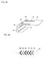
- a pair of color shift sensors 100 is provided opposite to each other on both sides in a width direction crossing the moving direction of the intermediate transfer belt 40 as shown in Fig. 3A , for example.
- the pair of color shift sensors 100 detect color shift detecting patterns M shown in Figs. 3A and 3B .
- the color shift detecting patterns M are formed at predetermined timings by using the image forming sections 30 (30a to 30d).
- each color shifter detecting pattern M is a V-shaped pattern, which protrudes in the moving direction of the intermediate transfer belt 40, is bent at an angle of 90 degrees, and is formed with a corresponding color toner.
- the example is configured so that color shifts in the color shift detecting patterns Ma to Mc for Y, M and C colors are detected based on the color shift detecting pattern Md for K color.
- the color shift sensor 100 (one example of the image position detecting device) includes a light irradiating unit 110 and a photodetector 120 in a sensor container 101 as shown in Fig. 4 .
- the light irradiating unit 110 irradiates the color shift detecting pattern M (Ma to Md) on the intermediate transfer belt 40 with light.
- the photodetector 120 which is provided separately from the light irradiating unit 110, detects light regularly reflected by the color shift detecting pattern M (Ma to Md) on the intermediate transfer belt 40.
- the light irradiating unit 110 is disposed on an upstream side, in the moving direction of the intermediate transfer belt 40, with being opposite to the photodetector 120 across a vertical line H passing through a light irradiated part of the intermediate transfer belt 40.
- An arrow shown in Fig. 4 indicates a travel direction of the intermediate transfer belt 40.
- the light irradiating unit 110 and the photodetector 120 are arranged along the travel direction of the intermediate transfer belt 40.
- the light irradiating unit 110 is disposed on the upstream side of the photodetector 120 in the moving direction of the intermediate transfer belt 40.
- the light irradiating unit 110 includes a light emitting portion 111 and an optical guiding lens 112.
- the light emitting portion 111 such as an LED, emits only light having a wavelength in an ultraviolet range.
- the optical guiding lens 112 changes the light emitted from the light emitting portion 111 into a parallel beam and irradiates the color shift detecting pattern M (Ma to Md) with the parallel beam.
- the photodetector 120 includes a light receiving portion 121 and an optical imaging lens 122.
- the light receiving portion 121 detects the light regularly reflected by the color shift detecting pattern M (Ma to Md).
- the optical imaging lens 122 is provided on a front side of the light receiving portion 121 and focuses the light regularly reflected by the color shift detecting pattern M (Ma to Md) to form an image on the light receiving portion 121.
- Reference numeral 130 denotes a substrate on which the photodetector 120 is mounted.
- the light receiving portions 121 of the photodetector 120 have such a pair structure that the light receiving portions 121 are separation from each other with being opposite to each other across a central axis O.
- the light receiving portions 121 (121a, 121 b) having the pair structure are disposed so as to correspond to the color shift detecting pattern M (Ma to Md) of the V-shaped pattern.
- the light receiving portion 121 a is divided into two light receiving cells PD1 and PD2, and the light receiving portion 121b is divided into two light receiving cells PD3 and PD4.
- An output characteristic of the light receiving portion 121 of the photodetector 120 shows a sine waveform which has the central axis O as a boundary as shown in Fig. 6A , for example. Therefore, it is possible to grasp a position of a central part (corresponding to a tip part of the V shape) of the color shift detecting pattern M (Ma to Md) more accurately as compared with a comparative example shown in Fig. 6B (in which a light receiving portion of a photodetector is formed of a single light receiving cell), for example.
- the color shift detecting pattern Md for the K color and the color shift detecting pattern Ma for the Y color are shifted from each other in the width direction of the intermediate transfer belt 40, for example, it is possible to grasp a relative position of the color shift detecting pattern Ma for the Y color with respect to the color shift detecting pattern Md for the K color based on a distance A in the moving direction of the intermediate transfer belt 40 between a position of a central part of the color shift detecting pattern Md for the K color and the color shift detecting pattern Ma for the Y color as shown in Fig. 5B .
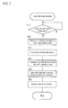
- control device 80 determines as to whether or not a color shift control timing comes (step S10).
- the color shift control timing may be selected appropriately. Examples of the color shift control timing include a timing at which a first job has been started since power is turned on and a timing whenever the certain number of sheets is printed.
- control device 80 determines that the color shift control timing comes (Yes at step S10), the control device 80 controls each image forming section 30 (30a to 30d) to from the color shift detecting pattern M (Ma to Md) for the corresponding color (step S20).
- control device 80 checks an output of the color shift sensor 100 (step S30) and calculates a color shift amount of each color shift detecting pattern M (Ma to Md) (step S40). Then, the control device 80 determines a color shift correcting amount for each color component and executes color shift correction (for example, corrects a writing start position of an electrostatic latent image for each color component image) (step S50).
- the color shift sensor 100 uses light having a wavelength (for example, 395 nm) in the ultraviolet range. Therefore, as show in Figs. 8A to 8D , reflectivities of the color shift detecting patterns Ma to Md of the respective color components (Y, M, C and K) are approximately 10% and are almost equal to each other for. Therefore, it can be understood that a variation in sensor sensitivity is small.
- the detection sensitivities of the color shift sensor 100 for the color shift detecting patterns M are almost equal.
- the detection sensitivities of the color shift sensor 100 can be maintained with high accuracy.
- the light emitting portion 111 of the light irradiating unit 110 in the color shift sensor 100 emits only the light having the wavelength in the ultraviolet range.
- the light emitting portion 111 of the light irradiating unit 110 may emit light having a wavelength in a range other than the ultraviolet range as well as the light having the wavelength in the ultraviolet range.
- the photodetector 120 is provided with an optical filter 123 that eliminates the light having the wavelength in the range other than the ultraviolet range, for example.
- Fig. 10 shows a color shift sensor (one example of the image position detecting device) according to a second exemplary embodiment.
- the basic configuration of the color shift sensor 100 (one example of the image position detecting device) is similar to that of the first exemplary embodiment and is different from that of the first exemplary embodiment in that a substrate 130 is inclined so as to decrease a difference between (i) an optical path length between one of the light receiving portions 121 and the irradiated color shift detecting mark M (Ma to Md) and (ii) an optical path length between the other light receiving portion 121 and the irradiated color shift detecting mark M (Ma to Md).
- the intermediate transfer belt travels from the right side to the left side as in Fig. 4 .
- the second exemplary embodiment it is possible to properly incline a light receiving surface of the light receiving portions 121 of the photodetector 120 having the pair structure by optimally setting a inclination posture of the substrate 130. Also, in the second exemplary embodiment, it is possible to suppress the difference between the optical path lengths to the light receiving portions 121 of the photodetector 120 having the pair structure. Therefore, the light regularly reflected by the color shift detecting pattern M forms an image in a small amount of out-of-focus from the light receiving portion 121. Thus, higher accuracy in detection sensitivities of the color shift sensor 100 can be achieved.
- Figs. 11 A and 11B show a color shift sensor (one example of the image position detecting device) according to a third exemplary embodiment.
- the basic configuration of a color shift sensor 100 (one example of the image position detecting device) is similar to that of the first exemplary embodiment and is different from that of the first exemplary embodiment in that a light irradiating unit 110 and a photodetector 120 are disposed so that the light irradiating unit 110 is located in a direction extending along a centerline of light receiving portions 121 of the photodetector 120 having a pair structure so as to decrease a difference between (i) an optical path length between one of the light receiving portions 121 and the irradiated color shift detecting mark M (Ma to Md) and (ii) an optical path length between the other light receiving portion 121 and the irradiated color shift detecting mark M (Ma to Md).
- the intermediate transfer belt travels from the rear side of the paper of Fig. 11 B to the front side thereof.
- the light irradiating unit 110 particularly, light emitting portion 111
- the photodetector 120 particularly, light receiving portions 121 are arranged along a direction substantially perpendicular to the travel direction of the intermediate transfer belt.
- a position where the color shift sensor 100 is provided is rotated by 90 degrees around a virtual line axis of the intermediate transfer belt 40 in a vertical direction.
- higher accuracy in detection sensitivities of the color shift sensor 100 can be achieved.
- Fig. 12 shows a color shift sensor (one example of the image position detecting device) according to a fourth exemplary embodiment.
- the basic configuration of the color shift sensor 100 (one example of the image position detecting device) is similar to that of the third exemplary embodiment and is different from that of the third exemplary embodiment in that an optical imaging lens 122 is disposed with inclining at a predetermined angle ⁇ with respect to an axis of an optical path so as to decrease a difference between (i) an optical path length between one of the light receiving portions 121 and the irradiated color shift detecting mark M (Ma to Md) and (ii) an optical path length between the other light receiving portion 121 and the irradiated color shift detecting mark M (Ma to Md). It is noted that, in Fig.
- a circle having a dot therein represents that the intermediate transfer belt 40 travels the rear side of the paper of Fig. 12 to the front side thereof.
- the light irradiating unit 110 particularly, light emitting portion 111
- the photodetector 120 particularly, light receiving portions 121 are arranged along a direction substantially perpendicular to the travel direction of the intermediate transfer belt 40.
- the fourth exemplary embodiment it is possible to suppress the difference between the optical path lengths to the light receiving portions 121 of the photodetector 120 having the pair structure. Therefore, the light regularly reflected by the color shift detecting pattern M forms an image on the light receiving portions 121 with a small amount of out-of-focus. Thus, the detection sensitivities of the color shift sensor 100 can have higher accuracy.
- the color shift sensor 100 can also be used for such a high speed image forming apparatus because the color shift sensor 100 has highly accurate detection sensitivities.
- the light regularly reflected by the color shift detecting pattern M forms an image in a state of out-of-focus from the light receiving portions 121 having the pair structure, as shown in Fig. 14A or 14C .
- the detecting accuracy of the color shift sensor 100 is enhanced more greatly as compared with the case where a layout of the optical imaging lens 122 is not adjusted.
- Example 1 the color shift sensor 100 according to the fourth exemplary embodiment is used.
- a relationship between a focal length and color registration (color shift) in a lateral direction (-Lat) and a process direction (-Pro) for the Y, M and K colors is examined.
- the lateral direction is a widthwise direction of the intermediate transfer belt 40
- the process direction is a moving direction of the intermediate transfer belt 40.
- the lateral direction may be a direction perpendicular to the intermediate transfer belt 40
- the process direction may be a direction parallel to the intermediate transfer belt 40.
- the "focal length” means a focal length of an optical system between the color shift detecting pattern M and the light receiving portions 121 of the photodetector 120.
- the optimum focal length is 8.0 mm. It should be noted that although the optimum focal length of Example 1 is 8.0mm, the invention is not limited thereto.
- Comparative Example 1 in which a light irradiating unit emits only light having a wavelength in an infrared region, a relationship between the focal length and the color registration is examined on the same condition as that in Example 1. Consequently, examination results shown in Fig. 15B are obtained.
- Comparative Example 1 it can be understood that the color registration for the K color is increased with an increase in variation of the focal length as compared with the other color components (Y and M colors) and that higher accuracy in an assembling work of the color shift sensor 100 would be correspondingly indispensable. Consequently, it is concerned that the assembling work of the color shift sensor 100 might be burdensome.
- Example 2 the color shift sensor according to the second exemplary embodiment is used. A relationship between a process speed of an image forming apparatus and a sensor output of the color shift sensor is examined. Then, an examination result shown in Fig. 16 is obtained.
- the sensor output is reduced with an increase in process speed of the image forming apparatus.
- the color shift sensor has a high accuracy in sensor sensitivity. Therefore, even if the process speed is set to be high and the sensor output is reduced to some extent, detection accuracy of the color shift sensor is maintained to be excellent.
- Example 2 the detection accuracy of the color shift sensor is excellent on the condition that the process speed is 600 mm/sec or less.
- Example 3 the color shift sensor 100 according to the fourth exemplary embodiment is used.
- An NG region means that pattern detection accuracy of the color shift sensor is reduced, and it is impossible to detect patterns.
- An OK region means that high pattern detection accuracy of the color shift sensor is maintained.
- Example 3 it can be understood that detection accuracy of the color shift sensor can be maintained to be excellent even if the minimum pattern width is small to some extent in the case where the detecting area is set to be large.
Landscapes
- Physics & Mathematics (AREA)
- General Physics & Mathematics (AREA)
- Engineering & Computer Science (AREA)
- Microelectronics & Electronic Packaging (AREA)
- Control Or Security For Electrophotography (AREA)
- Color Electrophotography (AREA)
Applications Claiming Priority (1)
| Application Number | Priority Date | Filing Date | Title |
|---|---|---|---|
| JP2009171377A JP2011027848A (ja) | 2009-07-22 | 2009-07-22 | 画像位置検出装置及びこれを用いた画像形成装置 |
Publications (1)
| Publication Number | Publication Date |
|---|---|
| EP2282237A2 true EP2282237A2 (de) | 2011-02-09 |
Family
ID=43234260
Family Applications (1)
| Application Number | Title | Priority Date | Filing Date |
|---|---|---|---|
| EP10170068A Withdrawn EP2282237A2 (de) | 2009-07-22 | 2010-07-20 | Bildpositionserkennungsvorrichtung und Bilderzeugungsvorrichtung dafür |
Country Status (3)
| Country | Link |
|---|---|
| US (1) | US20110018949A1 (de) |
| EP (1) | EP2282237A2 (de) |
| JP (1) | JP2011027848A (de) |
Families Citing this family (1)
| Publication number | Priority date | Publication date | Assignee | Title |
|---|---|---|---|---|
| JP7303995B2 (ja) * | 2019-02-27 | 2023-07-06 | ブラザー工業株式会社 | 画像形成装置 |
Citations (2)
| Publication number | Priority date | Publication date | Assignee | Title |
|---|---|---|---|---|
| JP2004020769A (ja) | 2002-06-14 | 2004-01-22 | Matsushita Electric Ind Co Ltd | カラー画像形成装置 |
| JP2006251686A (ja) | 2005-03-14 | 2006-09-21 | Canon Inc | 画像形成装置 |
Family Cites Families (3)
| Publication number | Priority date | Publication date | Assignee | Title |
|---|---|---|---|---|
| US3730133A (en) * | 1970-03-05 | 1973-05-01 | American Cyanamid Co | Apparatus for remote marking of articles of manufacture |
| US5634731A (en) * | 1994-03-04 | 1997-06-03 | Dai Nippon Printing Co., Ltd. | Method and apparatus for thermal transfer printing |
| JP3079076B2 (ja) * | 1997-03-19 | 2000-08-21 | 富士通株式会社 | 画像形成装置 |
-
2009
- 2009-07-22 JP JP2009171377A patent/JP2011027848A/ja active Pending
-
2010
- 2010-07-20 EP EP10170068A patent/EP2282237A2/de not_active Withdrawn
- 2010-07-21 US US12/840,631 patent/US20110018949A1/en not_active Abandoned
Patent Citations (2)
| Publication number | Priority date | Publication date | Assignee | Title |
|---|---|---|---|---|
| JP2004020769A (ja) | 2002-06-14 | 2004-01-22 | Matsushita Electric Ind Co Ltd | カラー画像形成装置 |
| JP2006251686A (ja) | 2005-03-14 | 2006-09-21 | Canon Inc | 画像形成装置 |
Also Published As
| Publication number | Publication date |
|---|---|
| US20110018949A1 (en) | 2011-01-27 |
| JP2011027848A (ja) | 2011-02-10 |
Similar Documents
| Publication | Publication Date | Title |
|---|---|---|
| US8279491B2 (en) | Color image formation apparatus for forming a reference pattern with a plurality of lines having a black color as reference color and for correcting misalignment with respect to the reference pattern | |
| US7917045B2 (en) | Image forming apparatus and image forming method | |
| US7055928B2 (en) | Alignment pattern detecting sensor, method of determining acceptance width of the alignment pattern detecting sensor, method of forming alignment pattern, and image forming apparatus | |
| US8422033B2 (en) | Reflective optical sensor and image forming apparatus | |
| JP5434694B2 (ja) | 位置ずれ補正方法及び位置ずれ補正装置、並びにそれを用いた画像形成装置 | |
| US20120224191A1 (en) | Image Forming Apparatus | |
| JP4419101B2 (ja) | 画像形成装置 | |
| US9116453B2 (en) | Image forming apparatus | |
| JP5262646B2 (ja) | 画像検出装置及び多色画像形成装置 | |
| US7660552B2 (en) | Image forming apparatus and test pattern | |
| JP6675344B2 (ja) | 光学センサ及び画像形成装置 | |
| EP2282237A2 (de) | Bildpositionserkennungsvorrichtung und Bilderzeugungsvorrichtung dafür | |
| US7428388B2 (en) | Image formation apparatus with image correction capability | |
| JP3958195B2 (ja) | 画像形成装置 | |
| JP2006084565A (ja) | カラー画像形成装置 | |
| JP5114256B2 (ja) | 画像形成装置および画像形成方法 | |
| JP7424202B2 (ja) | 画像形成装置 | |
| JP6849889B2 (ja) | 光学センサ及び画像形成装置 | |
| JP3920868B2 (ja) | 画像形成装置 | |
| JP2008096807A (ja) | カラー画像形成装置及び色ずれ補正方法 | |
| JP2006153676A (ja) | 光学式エンコーダ装置及び画像形成装置 | |
| JP2007079605A (ja) | 位置合わせパターン検知センサ・画像形成装置・色ずれ検知方法・色ずれ補正方法 | |
| JP2025154184A (ja) | 受発光センサ及び該受発光センサを備えた画像形成装置 | |
| JP2025154188A (ja) | 受発光センサ及び該受発光センサを備えた画像形成装置 | |
| JP2025154187A (ja) | 受発光センサ及び該受発光センサを備えた画像形成装置 |
Legal Events
| Date | Code | Title | Description |
|---|---|---|---|
| PUAI | Public reference made under article 153(3) epc to a published international application that has entered the european phase |
Free format text: ORIGINAL CODE: 0009012 |
|
| AK | Designated contracting states |
Kind code of ref document: A2 Designated state(s): AL AT BE BG CH CY CZ DE DK EE ES FI FR GB GR HR HU IE IS IT LI LT LU LV MC MK MT NL NO PL PT RO SE SI SK SM TR |
|
| AX | Request for extension of the european patent |
Extension state: BA ME RS |
|
| STAA | Information on the status of an ep patent application or granted ep patent |
Free format text: STATUS: THE APPLICATION HAS BEEN WITHDRAWN |
|
| 18W | Application withdrawn |
Effective date: 20140117 |