EP2281397B1 - Beleuchtungs- und anzeigevorrichtung - Google Patents
Beleuchtungs- und anzeigevorrichtung Download PDFInfo
- Publication number
- EP2281397B1 EP2281397B1 EP09757276.2A EP09757276A EP2281397B1 EP 2281397 B1 EP2281397 B1 EP 2281397B1 EP 09757276 A EP09757276 A EP 09757276A EP 2281397 B1 EP2281397 B1 EP 2281397B1
- Authority
- EP
- European Patent Office
- Prior art keywords
- lighting
- light
- display
- light emission
- emission surface
- Prior art date
- Legal status (The legal status is an assumption and is not a legal conclusion. Google has not performed a legal analysis and makes no representation as to the accuracy of the status listed.)
- Active
Links
- 238000005286 illumination Methods 0.000 title description 15
- 238000009413 insulation Methods 0.000 claims description 7
- 239000000463 material Substances 0.000 claims description 6
- 239000004973 liquid crystal related substance Substances 0.000 claims description 4
- 230000000694 effects Effects 0.000 description 3
- 230000005855 radiation Effects 0.000 description 3
- 239000003086 colorant Substances 0.000 description 1
- 238000013016 damping Methods 0.000 description 1
- 230000003247 decreasing effect Effects 0.000 description 1
- 230000001419 dependent effect Effects 0.000 description 1
- 238000010586 diagram Methods 0.000 description 1
- 238000005516 engineering process Methods 0.000 description 1
- 239000011159 matrix material Substances 0.000 description 1
- 230000003287 optical effect Effects 0.000 description 1
- 239000013589 supplement Substances 0.000 description 1
Images
Classifications
-
- H—ELECTRICITY
- H04—ELECTRIC COMMUNICATION TECHNIQUE
- H04N—PICTORIAL COMMUNICATION, e.g. TELEVISION
- H04N9/00—Details of colour television systems
- H04N9/12—Picture reproducers
-
- H—ELECTRICITY
- H04—ELECTRIC COMMUNICATION TECHNIQUE
- H04N—PICTORIAL COMMUNICATION, e.g. TELEVISION
- H04N5/00—Details of television systems
- H04N5/74—Projection arrangements for image reproduction, e.g. using eidophor
Definitions
- the invention relates to a lighting and display device which has a display with a first light-emitting surface and a lighting element with a second light-emitting surface. Furthermore, the invention relates to a lighting and display device with a projector for projecting images and a lighting element with a light-emitting surface.
- a “lighting and display device” is understood to mean a device which serves on the one hand for lighting and on the other hand for displaying, in particular for displaying information.
- a “lighting element” is understood to mean a means for lighting, in particular for lighting a room or a room area.
- a lighting element has means for generating light;
- the light-emitting element can have a light-emitting surface, from which the light generated can be emitted or emitted to an environment of the light-emitting element.
- a “display” is understood to mean a display unit of an electronic device, for example a display unit of a computer.
- a display can be used to generate light which can be emitted via a light-emitting surface of the display, specifically in such a way that a display can be visibly displayed on the light-emitting surface.
- the display can have light-emitting diodes (LEDs or light-emitting diodes); a liquid crystal display can also be provided.
- the lighting element In the case of a lighting element, it is generally desirable for the lighting element to be designed in such a way that it can be arranged advantageously and in a space-saving manner in an environment to be illuminated with the lighting element, that is to say, for example, in a room or room area to be illuminated. In addition, of course, the lighting element should be able to provide as much light as is desired for lighting.
- WO 2007/1313334 A1 a multi-pixel display is known that is suitable for displaying graphics on the one hand, but also as a lighting element on the other.
- a display system which has a display with a light-emitting surface. Another area is formed around the light emitting surface, onto which an image can be projected.
- a device with a display which can be, for example, a TV set. Images are projected onto the wall areas of the room adjacent to the display.
- a display is known, on the two sides of which a lateral display is connected. Projectors are used to generate images on the side displays.
- the US 6,611,297 B1 shows, inter alia, a lighting arrangement in which a projector mounted on a ceiling illuminates a wall area located below the projector, a display for displaying video information being arranged within the illuminated wall area.
- the JP H11 144510 A describes a lighting system in which an LCD display is provided in the center of an arrangement arranged on the ceiling of a room and is surrounded by a diffusely emitting lighting arrangement.
- the object of the present invention is to provide an improved lighting and display device. Illumination options are to be improved, in particular with a space-saving design.
- a lighting and display device which has a display with a first light-emitting surface and a lighting element with a second light-emitting surface.
- the first light-emitting surface is smaller than the second light-emitting surface and is arranged in a central region with respect to the outer boundary of the second light-emitting surface.
- the device If the device is to be used for lighting, light can be emitted for this purpose both via the light-emitting surface of the lighting element and via the light-emitting surface of the display.
- the type of arrangement mentioned allows the light-emitting surface of the display to be functionally integrated into the light-emitting surface of the lighting element, so that overall a light-emitting surface that is enlarged in this sense is available for illumination. In this way, the light emission options and thus the lighting options are improved.
- the display represents an extension part of the lighting element, so that no special space is required for the display. Therefore, the device as a whole is particularly space-saving.
- Both the display and the lighting element are designed to display individual pixels on the respective light-emitting surface, the display being designed to display more pixels per unit area than the lighting element.
- the display advantageously has light sources in the form of LEDs or a liquid crystal display.
- the lighting element advantageously has light sources in the form of LEDs. It can also be advantageously provided that a material for acoustic insulation is arranged in the radiation direction in front of the LEDs of the lighting element. In this way the lighting and display device can be used in a particularly space-saving manner in addition to acoustic insulation.
- the display is designed to emit light in the same or in a similar color and / or in the same or in a similar brightness as the lighting element. If light is emitted via both light-emitting surfaces, the impression of an overall particularly uniformly illuminating surface can be created in this way.
- the shortest distance between the first light-emitting surface and the second light-emitting surface is advantageously comparatively small, for example a maximum of half the diameter of the first light-emitting surface, preferably a maximum of one-tenth the diameter of the first light-emitting surface. This also contributes to an impression of a particularly uniform and evenly illuminating surface when light is emitted via both light emitting surfaces.
- the first light-emitting surface and the second light-emitting surface are advantageously arranged essentially within one plane, preferably between two parallel planes, the spacing of which is as large as half the diameter of the first light-emitting surface, preferably as large as a tenth of the diameter of the first light-emitting surface.
- Such an arrangement allows the device to be arranged in a particularly space-saving manner in a room, for example in front of a wall of the room.
- the lighting and display device advantageously also has a control unit for controlling the display and the lighting element. This makes operation easier, in particular when setting lighting by means of both light emitting surfaces.
- a combination of three lighting and display devices according to the invention is provided, a first and a second lighting and display device having a combination of features according to the first-mentioned aspect of the invention, that is to say in particular each having a display and a lighting element, and wherein a third lighting and display device has a combination of features as described below, that is to say in particular has a projector and a lighting element.
- the light-emitting surface has an opening in a central area, the projector being arranged relative to the lighting element in such a way that images can be projected through the opening with the projector.
- the projector can not only be used to project images, but also to illuminate a work surface or the surroundings of a work surface.
- the lighting and display device is attached to a ceiling of a room, so that the light-emitting surface is aligned parallel to the ceiling and can be projected with the projector onto a projection surface below the light-emitting surface.
- a work surface for example a table surface, can serve as the projection surface.
- the projector can then either produce an image on the projection surface, for example in the form of a display, or the projection surface can be illuminated with a uniform light, so that an illumination function is fulfilled.
- the lighting element advantageously has light sources in the form of LEDs. It can also be advantageously provided that a material for acoustic insulation is arranged in front of the LEDs in the direction of radiation.
- the second lighting and display device has an additional light for illuminating a work surface, which connects to the second light-emitting surface of the second lighting and display device.
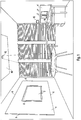
- Fig. 1 shows an example of a work space in the form of an office with a total of three embodiments of lighting and display devices according to the invention.
- Today's typical main activities in an office include concentrated work, telecommunications, video conferencing, meetings, etc.
- modern electronic media such as computers with Internet access etc. are used, which are generally becoming increasingly versatile and intuitive to use .
- the invention offers a particularly advantageous one Lighting and display devices (hereinafter also referred to as "device"), the possible use of the invention not being restricted to the environment of an office.
- a lighting and display device according to the invention can also be used in a private room area, in a hall or in principle also outdoors.
- a first embodiment of a device according to the invention is shown, which is also referred to below briefly as "video conference unit".
- the device comprises a display which is arranged on the relevant wall of the room and which has a first light-emitting surface 2 or “light-emitting surface 2 of the display”.
- a "light emitting surface” is a surface from which light can be actively emitted.
- the display is used to show information. It therefore represents a display device and can be connected, for example, to a conventional computer known per se in such a way that it accordingly serves as a display for this computer. Means known per se such as wireless mouse or keyboard units can be provided as an interface to the computer.
- the display can be, for example, a display device based on plasma technology or an LCD (Liquid Crystal Display).
- the screen diagonal of the display can be, for example, between 80 and 140 cm.
- a lighting element can be seen for illuminating an environment of the device, for example for illuminating the room.
- the light-emitting element has a second light-emitting surface 4 or a “light-emitting surface 4 of the light-emitting element”, which is larger than the first light-emitting surface 2. It can be provided that the light-emitting element is designed to generate a diffuse light.
- a matrix arrangement of LEDs can be provided as the light source. In this case, LEDs can be provided that can produce colored light, in short “colored” LEDs, for example “RGB LEDs” and / or LEDs that can generate white light, in short “white LEDs”.
- the second light-emitting surface 4 has an outer boundary 6, which is rectangular in the example shown.
- the mutual arrangement of the two light-emitting surfaces 2, 4 is such that the first light-emitting surface 2 is arranged in a central region with respect to the outer boundary 6 of the second light-emitting surface 4.
- the first Light-emitting surface 2 with respect to the outer boundary 6 of the second light-emitting surface 4 can be arranged in the center or “in the middle”.
- the device can be operated in two different modes, namely in a "lighting mode” and in a “display mode".
- the lighting mode the device is provided, at least primarily, for lighting an environment of the device, that is to say, for example, for lighting the room.
- the display mode the device is provided, at least primarily, for displaying information using the display on the first light-emitting surface 2.
- the device can be used to emit light for illumination not only via the light-emitting surface 4 of the lighting element, but also additionally via the light-emitting surface 2 of the display. Due to the above-mentioned type of relative arrangement of the two light-emitting surfaces 2, 4, the light-emitting surface 2 of the display is, as it were, integrated into the light-emitting surface 4 of the lighting element, so that overall a quasi-uniform appearing and in this sense enlarged light-emitting surface is available for illumination. In this way, the light emission options of the device and thus the lighting options are improved.
- the boundaries between the two functional units of the "lighting" device on the one hand and "display” on the other hand are, so to speak, "blurred" in the device according to the invention.
- the display in this mode the display supplements the lighting element, so that in the lighting mode the lighting element and the display form a functional unit; in this case, the display is "integrated" into the lighting element. In this sense, it forms an "integrative" part in the lighting mode. Therefore, the device as a whole is particularly space-saving.
- the second light-emitting surface 4 can be arranged in a ring, specifically in the form of a closed ring around the first light-emitting surface 2.
- the light-emitting surface 2 of the display can be arranged approximately at eye level with respect to a person sitting or standing in the room, so that information displayed on the first light-emitting surface 2 is generally easy and good can be seen, while the light-emitting surface 4 of the lighting element is clearly above and below Light emitting surface extends beyond the display.
- the outer boundary 6 of the second light-emitting surface 4 is between 30 cm and 100 cm above the upper boundary of the first light-emitting surface 2.
- the same can also be provided for the lower boundaries and the two corresponding lateral boundaries. With an overall comparatively large light emission surface, a comparatively pleasant light for lighting can be generated.
- the two light-emitting surfaces 2, 4 cover a predominant part of the relevant wall of the room.
- the lengths of the sides of the outer boundary 6 of the second light-emitting surface 4 can be in the range of meters, for example between one and five meters.
- the display can advantageously be designed to emit light in the same or in a similar color and / or in the same or in a similar brightness or intensity as the lighting element.
- "white light” of the same brightness or at least similar brightness can be emitted from both light emission surfaces 2, 4.
- illumination can be achieved in the illumination mode in which the light emission via the two light emission surfaces 2, 4 appears particularly homogeneous; overall, a particularly uniform "light image” can be produced in this way.
- “similar” color refers to a color that is located in an equally spaced color diagram within a small environment of the color of the light of the lighting element in question.
- a "similar" brightness or intensity is a brightness that deviates less than a small amount, for example less than 10%, from the relevant brightness or intensity of the light of the lighting element.
- the lighting element is advantageously designed to emit light of different colors and / or brightness in different areas of the second light emitting surface.
- it can be provided in the display mode that the lighting element can be controlled in such a way that light is emitted from the second light-emitting surface 4 in such a way that the contrast from the display on the first light-emitting surface 2 is reduced towards the outside.
- the control being able to be provided such that the display on the first light-emitting surface 2 is brightness and / or color outwards slowly decreasing "continued", namely under the lower resolution or pixel density of the lighting element compared to the display.
- the shortest distance between the first light-emitting surface 2 and the second light-emitting surface 4 is at most as large as half the diameter of the first light-emitting surface 2, preferably at most as large as one-tenth the diameter of the first light-emitting surface 2
- this distance is less than one tenth of the diameter of the first light-emitting surface 2 and is essentially only filled by a narrow frame 8, which can be part of the display and which surrounds the first light-emitting surface 2.
- the screen diagonal of the light-emitting surface 2 of the display is 110 cm; in this case, the diameter of the first light-emitting surface is 110 cm and a tenth of it is 11 cm, so that the space between the two light-emitting surfaces 2, 4 would have a width in this case that is less than 11 cm at any point.
- the device can furthermore have a camera (not shown in the figure), which is connected to a computer together with the display in such a way that a video conference can be carried out with it.
- the camera can be arranged, for example, in the area of the frame 8, for example embedded in the frame 8.
- the display is used for the display, for example for displaying information such as is typically shown on a display when working with a computer, a correspondingly high resolution or pixel density is provided for the display.
- the display is designed to be able to display or resolve more pixels per unit area than the lighting element, since information about the second light emitting surface 4 is not provided.
- the device as a whole can be designed with a large area in relation to a room, it is also particularly suitable for being arranged in front of a wall, as is the case in the example shown in front of the left wall. For this reason, it can also be particularly advantageous to arrange a material in front of the light source of the second light-emitting surface 4, that is to say for example in front of the corresponding LEDs, which is permeable to light, but has a damping effect with respect to acoustics or sound. On in this way the device can also provide acoustic insulation. For example, an acoustic panel made of transparent honeycomb material can be provided for this.
- the device can be designed to be particularly space-saving if the two light-emitting surfaces 2, 4 are arranged essentially in one plane and the total extent of the device perpendicular to this plane, that is to say its “strength” or “thickness”, is comparatively small.
- the first light-emitting surface 2 and the second light-emitting surface 4 are arranged between two parallel planes, the spacing of which is as large as half the diameter of the first light-emitting surface 2, preferably as large as a tenth of the diameter of the first light-emitting surface 2 can of course also be provided that the two light-emitting surfaces 2, 4 are arranged in one plane. This further promotes a particularly uniform appearance of the two light-emitting surfaces in the illumination mode.
- a control unit for controlling the display and the lighting element is also provided.
- the control unit is preferably designed to switch the two modes mentioned, ie the lighting mode and the display mode, on or off. It can preferably be provided that the light emitted by the first light-emitting surface 2 can be adjusted in terms of its brightness and color to the light that is emitted by the second light-emitting surface 4 with the control unit in the illumination mode, preferably in such a way that the light diffuses that emits from the first light emitting surface 2 differs as little as possible from the light emitted from the second light emitting surface 4. This facilitates the operation of the device when the lighting mode is set.
- a second exemplary embodiment of a lighting and display device according to the invention is shown on the right-hand side, which is also referred to below for short as an “office table unit”. Only differences from the first exemplary embodiment are discussed below. Unless otherwise stated, the explanations for the first exemplary embodiment apply analogously or analogously.
- the first light-emitting surface is composed of a plurality, in the example shown, of two separate segments 2 'and 2 ".
- the two segments 2 ', 2 " can each represent displays that are connected to a computer or each to a computer.
- the second light-emitting surface 4' is predominantly to the right and left of the two segments 2 ', 2" the first light emitting surface is arranged.
- the two segments 2 ', 2 " can, so to speak, be” embedded "in the second light-emitting surface 4'.
- the two light-emitting surfaces 2 ', 2" and 4' form a "light wall".
- the two light-emitting surfaces 2 ', 2 "and 4' are arranged essentially vertically, specifically on a rear boundary of a horizontal work surface 10, which can be an office table surface, for example.
- an additional light 12 can be provided in this case, with which the work surface 10 can be illuminated from above, so that an "accent lighting" can be generated.
- a lamp based on a mirror projector can be provided for this purpose.
- the mirror can be attached to the lighting element, for example in the area of the upper boundary of the second light-emitting surface 4 or the “light wall”.
- the mirror is pivotable and can be moved by a motor.
- a camera can also be attached to the mirror with which an image of the work surface 10 can be captured, so that an active tracking of the mirror with the aid of the motor is made possible on this basis.
- automatic focusing of the projection surface or work surface can be provided.
- the light which is emitted by the second light-emitting surface 4 ', is selected in intensity and color such that a contrast reduction between the first light-emitting surface or the two segments 2', 2 "of the first light-emitting surface and the Backlight is achieved.
- a further example of a lighting and display device can be seen, which is also briefly referred to below as "ceiling unit”.
- This has a projector (not visible in the figure as such) for projecting images, and a lighting element with a light-emitting surface 40.
- the projector can be, for example, a device usually referred to as a "video projector”.
- the light emitting surface 40 is oriented parallel to the ceiling, that is to say essentially horizontally.
- the projector is arranged so that it can be projected downwards.
- the explanations for the first exemplary embodiment also apply mutatis mutandis to this third exemplary embodiment.
- the device can be operated both in a "lighting mode” and in a "display mode”.
- the light emitting surface 40 corresponds to the light emitting surface 4 of the lighting element in the first exemplary embodiment; Unless otherwise shown, the light-emitting surface 40 can therefore have the same features as the second light-emitting surface 4 in the first exemplary embodiment. In particular, it can in turn be provided that LEDs are provided as light sources and that a translucent acoustic insulation is arranged in front of these LEDs in the direction of radiation.
- the light-emitting surface 40 has an opening 42.
- the projector is arranged relative to the lighting element in such a way that images can be projected downward through the opening 42 with the projector.
- the projector comprises an optical system which is arranged in the area of the opening 42 or in the opening 42. It can be provided that the projector is, so to speak, "embedded" in the lighting element or in the light-emitting surface 40 of the lighting element.
- a table with a table surface 50 is arranged below the device, so that the table surface 50 serves as a projection surface for the projector.
- the projector is designed to project an image which corresponds to a display such as can be shown on the light-emitting surface 2 of the display in the first exemplary embodiment.
- the projector can be connected to a computer.
- Means known per se, such as wireless mouse or keyboard units, can in turn be provided as an interface to the computer.
- the projector is designed to emit a uniform light in the illumination mode, so that the corresponding projection surface, in this case the table surface 50 or a partial area of the table surface 50, is illuminated uniformly.
- the projector can be used in lighting mode Take on the function of a spotlight.
- color-neutral white lighting can be provided for this.
- a corresponding tracking of the light cone is again possible, as has been shown above for the additional light 12 in the office table unit.
- the double function of the projector which serves as display means in the display mode and as the illumination means in the illumination mode, is particularly advantageous here.
- Fig. 1 shown combination of three lighting and display devices according to the invention is particularly suitable for use in an office environment.
- the "video conference unit” video conferences can be carried out.
- the "office table unit” is suitable for concentrated work and telecommunications and the "ceiling unit” for a meeting.
- the combination shown is particularly suitable for essential, typical main activities in the work environment of an office.
- a combination of two lighting and display devices according to the invention is of course also advantageous.
- the "video conference unit” can be combined with the "office table unit” and the same applies to the other possible sub-combinations.
- a common computer preferably with a USB connection, that is to say an “office PC”, can be provided, which can be connected to all the devices accordingly. If necessary, the mirror projector can also be adjusted using this computer.
Landscapes
- Engineering & Computer Science (AREA)
- Multimedia (AREA)
- Signal Processing (AREA)
- Devices For Indicating Variable Information By Combining Individual Elements (AREA)
- Control Of Indicators Other Than Cathode Ray Tubes (AREA)
Description
- Die Erfindung betrifft eine Beleuchtungs- und Anzeigevorrichtung, die ein Display mit einer ersten Lichtabgabefläche und ein Leuchtelement mit einer zweiten Lichtabgabefläche aufweist. Weiterhin betrifft die Erfindung eine Beleuchtungs- und Anzeigevorrichtung mit einem Projektor zur Projektion von Bildern und einem Leuchtelement mit einer Lichtabgabefläche.
- Unter einer "Beleuchtungs- und Anzeigevorrichtung" wird im vorliegenden Rahmen eine Vorrichtung verstanden, die zum einen zur Beleuchtung dient und zum anderen zur Anzeige, insbesondere zur Anzeige von Informationen.
- Unter einem "Leuchtelement" wird im vorliegenden Rahmen ein Mittel zur Beleuchtung, insbesondere zur Beleuchtung eines Raumes oder eines Raumbereichs verstanden. Ein Leuchtelement weist Mittel zur Lichterzeugung auf; weiterhin kann das Leuchtelement eine Lichtabgabefläche aufweisen, von der aus das erzeugte Licht an eine Umgebung des Leuchtelements abgegeben bzw. ausgestrahlt werden kann.
- Unter einem "Display" wird im vorliegenden Rahmen eine Anzeigeeinheit eines elektronischen Geräts verstanden, beispielsweise eine Anzeigeeinheit eines Computers. Mit einem Display kann Licht erzeugt werden, das über eine Lichtabgabefläche des Displays abgestrahlt werden kann, und zwar derart, dass auf diese Weise auf der Lichtabgabefläche eine Anzeige sichtbar dargestellt werden kann. Zur Lichterzeugung kann das Display Licht emittierende Dioden (LEDs bzw. Leuchtdioden) aufweisen; auch eine Flüssigkristallanzeige kann vorgesehen sein.
- Bei einem Leuchtelement ist in der Regel erwünscht, dass das Leuchtelement derart gestaltet ist, dass es sich vorteilhaft und raumsparend in einer mit dem Leuchtelement zu beleuchtenden Umgebung, also beispielsweise in einem zu beleuchtenden Raum oder Raumbereich, anordnen lässt. Außerdem soll selbstverständlich mit dem Leuchtelement so viel Licht zur Verfügung gestellt werden können, wie zur Beleuchtung erwünscht ist.
- Aus der
US 2007/0126864 A1 ist ein System bekannt, mit dem in einem ersten Bereich ein Video dargestellt werden kann und in einem zweiten Bereich, der um den ersten Bereich herum angeordnet ist, unterschiedliche Bilder, Muster oder dergleichen dargestellt werden können. - Aus der
WO 2007/1313334 A1 - Aus der
US 2002/0198438 A1 ist eine Überkopf-Anordnung mit einer Segeltuchabdeckung und einer Bildprojektionseinheit bekannt. - Aus der
EP 1 396 781 A2 ist ein Anzeigesystem bekannt, das ein Display mit einer Lichtabgabefläche aufweist. Um die Lichtabgabefläche herum ist eine weitere Fläche gebildet, auf die ein Bild projiziert werden kann. - Aus der
WO 2005/017739 A1 ist eine Vorrichtung mit einem Display bekannt, bei dem es sich beispielsweise um ein TV-Gerät handeln kann. Auf die, an das Display angrenzenden Wandbereiche des Raums werden Bilder projiziert. - Aus der
WO 2007/113754 A1 ist ein Display bekannt, auf dessen beiden Seiten sich jeweils ein seitliches Display anschließt. Zur Bilderzeugung auf den seitlichen Displays dienen Projektoren. - Aus der
EP 1379 917 A2 ist ein Projektor zur Projektion von Bildern auf einen Schirm bekannt. Aus derWO 2005/057921 A2 ist ebenfalls ein Projektor zur Projektion von Bildern auf einen Schirm bekannt. - Die
US 6,611,297 B1 zeigt u.a. eine Beleuchtungsanordnung, bei der ein an einer Decke montierter Projektor einen unterhalb des Projektors befindlichen Wandbereich beleuchtet, wobei innerhalb des beleuchteten Wandbereichs ein Display zur Darstellung von Video-Informationen angeordnet ist. - Die
JP H11 144510 A - Der vorliegenden Erfindung liegt die Aufgabe zu Grunde, eine verbesserte Beleuchtungs- und Anzeigevorrichtung anzugeben. Dabei sollen insbesondere bei insgesamt raumsparender Ausführung Möglichkeiten der Beleuchtung verbessert werden.
- Diese Aufgabe wird gemäß der Erfindung mit den in den unabhängigen Ansprüchen genannten Gegenständen gelöst. Bevorzugte Ausführungsformen der Erfindung sind in den abhängigen Ansprüchen angegeben.
- Gemäß der Erfindung ist eine Beleuchtungs- und Anzeigevorrichtung vorgesehen, die ein Display mit einer ersten Lichtabgabefläche und ein Leuchtelement mit einer zweiten Lichtabgabefläche aufweist. Die erste Lichtabgabefläche ist dabei kleiner als die zweite Lichtabgabefläche und mit Bezug auf die äußere Begrenzung der zweiten Lichtabgabefläche in einem mittleren Bereich angeordnet.
- Falls mit der Vorrichtung eine Beleuchtung durchgeführt werden soll, kann hierfür Licht sowohl über Lichtabgabefläche des Leuchtelements, als auch über die Lichtabgabefläche des Displays ausgestrahlt werden. Durch die genannte Art der Anordnung lässt sich dabei die Lichtabgabefläche des Displays in die Lichtabgabefläche des Leuchtelements funktionell integrieren, so dass insgesamt eine in diesem Sinne vergrößerte Leichtabgabefläche zur Beleuchtung zur Verfügung steht. Auf diese Weise sind die Lichtabgabemöglichkeiten und damit die Beleuchtungsmöglichkeiten verbessert. Außerdem stellt in diesem Fall durch die integrative Anordnung das Display gleichsam einen Erweiterungsteil des Leuchtelements dar, so dass für das Display kein gesonderter Platz erforderlich ist. Daher ist die Vorrichtung insgesamt besonders raumsparend.
- Sowohl das Display als auch das Leuchtelement sind dazu ausgelegt, auf der jeweiligen Lichtabgabefläche einzelne Bildpunkte darzustellen, wobei das Display dazu ausgelegt ist, mehr Bildpunkte pro Flächeneinheit darzustellen als das Leuchtelement.
- Vorteilhaft weist das Display Lichtquellen in Form von LEDs oder eine Flüssigkristallanzeige auf.
- Vorteilhaft weist das Leuchtelement Lichtquellen in Form von LEDs auf. Dabei kann weiterhin vorteilhaft vorgesehen sein, dass in Abstrahlrichtung vor den LEDs des Leuchtelements ein Material zur Akustikdämmung angeordnet ist. Auf diese Weise lässt sich die Beleuchtungs- und Anzeigevorrichtung besonders raumsparend zusätzlich zur Akustikdämmung verwenden.
- Erfindungsgemäß ist das Display dazu ausgelegt, Licht in derselben oder in einer ähnlichen Farbe und/oder in derselben oder in einer ähnlichen Helligkeit abzugeben, wie das Leuchtelement. Wenn über beide Lichtabgabeflächen Licht abgegeben wird, kann auf diese Weise der Eindruck einer insgesamt besonders gleichmäßig leuchtenden Fläche bewirkt werden.
- Vorteilhaft ist die kürzeste Entfernung zwischen der ersten Lichtabgabefläche und der zweiten Lichtabgabefläche vergleichsweise klein, zum Beispiel maximal so groß wie der halbe Durchmesser der ersten Lichtabgabefläche, vorzugsweise maximal so groß wie ein Zehntel des Durchmessers der ersten Lichtabgabefläche. Auch dies trägt bei Lichtabgabe über beide Lichtabgabeflächen zu einem Eindruck einer besonders einheitlich und gleichmäßig leuchtenden Fläche bei.
- Vorteilhaft sind die erste Lichtabgabefläche und die zweite Lichtabgabefläche im Wesentlichen innerhalb einer Ebene angeordnet, vorzugsweise zwischen zwei parallelen Ebenen, deren Abstand so groß ist wie der halbe Durchmesser der ersten Lichtabgabefläche, vorzugsweise so groß wie ein Zehntel des Durchmessers der ersten Lichtabgabefläche. Durch eine derartige Anordnung lässt sich die Vorrichtung insbesondere besonders raumsparend in einem Raum, beispielsweise vor einer Wand des Raums, anordnen.
- Vorteilhaft weist die Beleuchtungs- und Anzeigevorrichtung weiterhin eine Steuereinheit zur Ansteuerung des Displays und des Leuchtelements auf. Dies erleichtert die Bedienung insbesondere bei Einstellung einer Beleuchtung mittels beider Lichtabgabeflächen.
- Gemäß einem weiteren Aspekt der Erfindung ist eine Kombination aus drei erfindungsgemäßen Beleuchtungs- und Anzeigevorrichtungen vorgesehen, wobei eine erste und eine zweite Beleuchtungs- und Anzeigevorrichtung eine Merkmalskombination gemäß dem zuerst genannten Aspekt der Erfindung aufweisen, also insbesondere jeweils ein Display und ein Leuchtelement aufweisen und wobei eine dritte Beleuchtungs- und Anzeigevorrichtung eine Merkmalskombination wie nachfolgend beschrieben aufweist, also insbesondere einen Projektor und ein Leuchtelement aufweist. Dabei weist die Lichtabgabefläche in einem mittleren Bereich eine Öffnung auf, wobei der Projektor relativ zu dem Leuchtelement so angeordnet ist, dass mit dem Projektor Bilder durch die Öffnung hindurch projiziert werden können.
- Der Projektor kann nicht nur zur Projektion von Bildern verwendet werden, sondern auch zur Beleuchtung einer Arbeitsfläche bzw. einer Umgebung einer Arbeitsfläche. Beispielsweise kann vorgesehen sein, dass die Beleuchtungs- und Anzeigevorrichtung an einer Decke eines Raumes befestigt wird, so dass die Lichtabgabefläche parallel zur Decke ausgerichtet ist und mit dem Projektor auf eine Projektionsfläche unterhalb der Lichtabgabefläche projiziert werden kann. Als Projektionsfläche kann dabei eine Arbeitsfläche, beispielsweise eine Tischoberfläche dienen. Mit dem Projektor kann dann - je nach Bedarf - entweder auf der Projektionsfläche ein Bild, beispielsweise in Form einer Anzeige, erzeugt werden oder die Projektionsfläche kann mit einem gleichförmigen Licht bestrahlt werden, so dass eine Beleuchtungsfunktion erfüllt wird.
- Vorteilhaft weist dabei das Leuchtelement Lichtquellen in Form von LEDs auf. Dabei kann weiterhin vorteilhaft vorgesehen sein, dass in Abstrahlrichtung vor den LEDs ein Material zur Akustikdämmung angeordnet ist.
- Dabei kann vorteilhaft vorgesehen sein, dass die zweite Beleuchtungs- und Anzeigevorrichtung eine zusätzliche Leuchte zur Beleuchtung einer Arbeitsfläche aufweist, die an die zweite Lichtabgabefläche der zweiten Beleuchtungs- und Anzeigevorrichtung anschließt.
- Die Erfindung wird im Folgenden an Hand von Ausführungsbeispielen und mit Bezug auf die Zeichnung näher erläutert. Es zeigt:
- Fig. 1
- einen Arbeitsraum mit drei Ausführungsbeispielen einer erfindungsgemäßen Beleuchtungs- und Anzeigevorrichtung.
-
Fig. 1 zeigt beispielhaft einen Arbeitsraum in Form eines Büros mit insgesamt drei Ausführungsbeispielen von erfindungsgemäßen Beleuchtungs- und Anzeigevorrichtungen. Zu den heute typischen Haupttätigkeiten in einem Büro zählen beispielsweise konzentriertes Arbeiten, Telekommunikation, Durchführen von Videokonferenzen, Besprechungen usw. Dabei kommen üblicherweise moderne elektronische Medien, wie beispielsweise Computer mit Internetzugang usw. zum Einsatz, die im Allgemeinen immer vielseitiger und intuitiver in ihrer Bedienbarkeit werden. Vor diesem Hintergrund bietet die Erfindung eine besonders vorteilhafte Beleuchtungs- und Anzeigevorrichtungen (im Folgenden auch kurz "Vorrichtung" genannt), wobei die Einsatzmöglichkeit der Erfindung nicht auf das Umfeld eines Büros eingeschränkt ist. Beispielsweise kann eine erfindungsgemäße Beleuchtungs- und Anzeigevorrichtung auch in einem privaten Raumbereich, in einer Halle oder grundsätzlich auch im Freien eingesetzt werden. - Auf der linken Seite des in
Fig. 1 gezeigten Raumes ist ein erstes Ausführungsbeispiel einer erfindungsgemäßen Vorrichtung dargestellt, das im Folgenden auch kurz als "Videokonferenzeinheit" bezeichnet wird. Die Vorrichtung umfasst ein Display, das an der betreffenden Wand des Raums angeordnet ist und das eine erste Lichtabgabefläche 2 bzw. "Lichtabgabefläche 2 des Displays" aufweist. Mit "Lichtabgabefläche" sei dabei eine Fläche bezeichnet, von der aus aktiv Licht ausgesendet werden kann. - Das Display dient zur Anzeige von Informationen. Es stellt also eine Anzeigevorrichtung dar und kann beispielsweise derart mit einem an sich bekannten, üblichen Computer verbunden sein, dass es dementsprechend als Display für diesen Computer dient. Als Interface zum Computer können hierbei an sich bekannte Mittel wie drahtlose Maus- oder Tastatureinheiten vorgesehen sein. Bei dem Display kann es sich beispielsweise um eine Anzeigevorrichtung auf Basis der Plasma-Technologie oder um ein LCD (Liquid Crystal Display) handeln. Die Bildschirmdiagonale des Displays kann beispielsweise zwischen 80 und 140 cm betragen.
- Weiterhin erkennt man an der linken Wand des Raums ein Leuchtelement, zur Beleuchtung einer Umgebung der Vorrichtung, beispielsweise zur Beleuchtung des Raums. Das Leuchtelement weist eine zweite Lichtabgabefläche 4 bzw. eine "Lichtabgabefläche 4 des Leuchtelements" auf, die größer ist, als die erste Lichtabgabefläche 2. Dabei kann vorgesehen sein, dass das Leuchtelement dazu ausgelegt ist, ein diffuses Licht zu erzeugen. Als Lichtquelle kann eine Matrixanordnung von LEDs (Licht emittierenden Dioden) vorgesehen sein. Dabei können LEDs vorgesehen sein, die farbiges Licht erzeugen können, kurz "farbige" LEDs, also beispielsweise "RGB-LEDs" und/oder LEDs, die weißes Licht erzeugen können, kurz "weiße LEDs".
- Die zweite Lichtabgabefläche 4 weist eine äußere Begrenzung 6 auf, die im gezeigten Beispiel rechteckförmig ist. Die gegenseitige Anordnung der beiden Lichtabgabeflächen 2, 4 ist derart, dass die erste Lichtabgabefläche 2 mit Bezug auf die äußere Begrenzung 6 der zweiten Lichtabgabefläche 4 in einem mittleren Bereich angeordnet ist. Beispielsweise kann - wie im gezeigten Beispiel der Fall - die erste Lichtabgabefläche 2 mit Bezug auf die äußere Begrenzung 6 der zweiten Lichtabgabefläche 4 im Zentrum bzw. "mittig" angeordnet sein.
- Vorzugsweise ist vorgesehen, dass die Vorrichtung in zwei unterschiedlichen Modi betrieben werden kann, und zwar in einem "Beleuchtungsmodus" und in einem "Anzeigemodus". In dem Beleuchtungsmodus ist die Vorrichtung zumindest primär zur Beleuchtung einer Umgebung der Vorrichtung, also zum Beispiel zur Beleuchtung des Raums vorgesehen. Im "Anzeigemodus" ist die Vorrichtung zumindest primär zur Anzeige von Informationen mithilfe des Displays auf der ersten Lichtabgabefläche 2 vorgesehen.
- Im Beleuchtungsmodus kann mit der Vorrichtung Licht zur Beleuchtung nicht nur über die Lichtabgabefläche 4 des Leuchtelements, sondern zusätzlich auch über die Lichtabgabefläche 2 des Displays ausgestrahlt werden. Durch die genannte Art der relativen Anordnung der beiden Lichtabgabeflächen 2, 4 ist die Lichtabgabefläche 2 des Displays gleichsam in die Lichtabgabefläche 4 des Leuchtelements integriert, so dass insgesamt eine quasi einheitlich erscheinende und in diesem Sinne vergrößerte Lichtabgabefläche zur Beleuchtung zur Verfügung steht. Auf diese Weise sind die Lichtabgabemöglichkeiten der Vorrichtung und damit die Beleuchtungsmöglichkeiten verbessert. Die Grenzen zwischen den beiden funktionellen Einheiten der Vorrichtung "Beleuchtung" einerseits und "Anzeige" andererseits sind bei der erfindungsgemäßen Vorrichtung sozusagen "verschwommen".
- Außerdem wird dadurch erzielt, dass im Beleuchtungsmodus für das Display kein gesonderter Platz bzw. Raumbereich erforderlich ist, denn das Display ergänzt in diesem Modus das Leuchtelement, so dass im Beleuchtungsmodus das Leuchtelement und das Display eine funktionelle Einheit bilden; das Display ist also in diesem Fall insoweit in das Leuchtelement "eingebunden". Es bildet also im Beleuchtungsmodus in diesem Sinne einen "integrativen" Teil. Daher ist die Vorrichtung insgesamt besonders raumsparend.
- Die zweite Lichtabgabefläche 4 kann - wie im gezeigten Beispiel der Fall - ringförmig, und zwar in Form eines geschlossenen Rings um die erste Lichtabgabefläche 2 herum angeordnet sein. Bei den typischen Größenverhältnissen in einem Raum kann auf diese Weise die Lichtabgabefläche 2 des Displays - mit Bezug auf einen in dem Raum sitzenden oder stehenden Menschen - etwa in Augenhöhe angeordnet sein, so dass sich auf der ersten Lichtabgabefläche 2 dargestellte Informationen im Allgemeinen leicht und gut erkennen lassen, während sich die Lichtabgabefläche 4 des Leuchtelements nach oben und unten deutlich über die Lichtabgabefläche des Displays hinaus erstreckt. Beispielsweise kann vorgesehen sein, dass sich die äußere Begrenzung 6 der zweiten Lichtabgabefläche 4 zwischen 30 cm und 100 cm oberhalb der oberen Begrenzung der ersten Lichtabgabefläche 2 befindet. Analoges kann auch für die unteren Begrenzungen und die beiden entsprechenden seitlichen Begrenzungen vorgesehen sein. Mit einer insgesamt vergleichsweise großen Lichtabgabefläche lässt sich ein vergleichsweise angenehmes Licht zur Beleuchtung erzeugen.
- Im gezeigten Beispiel bedecken die beiden Lichtabgabeflächen 2, 4 einen überwiegenden Anteil der betreffenden Wand des Raums. Die Längen der Seiten der äußeren Begrenzung 6 der zweiten Lichtabgabefläche 4 können dabei im Bereich von Metern liegen, beispielsweise zwischen einem und fünf Metern.
- Das Display kann vorteilhaft dazu ausgelegt sein, Licht in derselben oder in einer ähnlichen Farbe und/oder in derselben oder in einer ähnlichen Helligkeit bzw. Intensität abzugeben, wie das Leuchtelement. Beispielsweise kann vorgesehen sein, dass von beiden Lichtabgabeflächen 2, 4 "Weißlicht" derselben Helligkeit oder zumindest ähnlicher Helligkeit abgegeben werden kann. Auf diese Weise kann im Beleuchtungsmodus eine Beleuchtung erzielt werden, bei der die Lichtabgabe über die beiden Lichtabgabeflächen 2, 4 besonders homogen erscheint; insgesamt lässt sich auf diese Weise ein besonders gleichförmiges "Lichtbild" bewirken. Mit "ähnlicher" Farbe sei in diesem Zusammenhang eine Farbe bezeichnet, die sich in einem gleichabständigen Farbdiagramm innerhalb einer kleinen Umgebung von der betreffenden Farbe des Lichts des Leuchtelements befindet. Mit "ähnlicher" Helligkeit bzw. Intensität sei eine Helligkeit bezeichnet, die weniger als ein kleines Maß, beispielsweise weniger als 10% von der betreffenden Helligkeit bzw. Intensität des Lichts des Leuchtelements abweicht.
- Vorteilhaft ist das Leuchtelement dazu ausgelegt, in unterschiedlichen Bereichen der zweiten Lichtabgabefläche Licht unterschiedlicher Farbe und/oder Helligkeit abzustrahlen. In diesem Fall kann im Anzeigemodus vorgesehen sein, dass das Leuchtelement so angesteuert werden kann, dass von der zweiten Lichtabgabefläche 4 derart Licht abgestrahlt wird, dass dadurch der Kontrast von der Anzeige auf der ersten Lichtabgabefläche 2 nach außen zu reduzierend verläuft. Es kann also insbesondere vorgesehen sein, dass auch im Anzeigemodus von der zweiten Lichtabgabefläche 4 zumindest innerhalb einer Umgebung der ersten Lichtabgabefläche 2 Licht abgestrahlt wird, wobei die Ansteuerung so vorgesehen sein kann, dass die Anzeige auf der ersten Lichtabgabefläche 2 hinsichtlich Helligkeit und/oder Farbe nach außen hin langsam abnehmend "weitergeführt" wird, und zwar unter der im Vergleich zum Display geringeren Auflösung bzw. Bildpunktdichte des Leuchtelements.
- Mit Bezug auf ein besonders einheitliches Lichtbild ist es auch vorteilhaft, wenn zwischen den beiden Lichtabgabeflächen 2, 3 kein oder nur ein vergleichsweise kleiner Abstand besteht. Dabei kann beispielsweise vorteilhaft vorgesehen sein, dass die kürzeste Entfernung zwischen der ersten Lichtabgabefläche 2 und der zweiten Lichtabgabefläche 4 maximal so groß ist wie der halbe Durchmesser der ersten Lichtabgabefläche 2, vorzugsweise maximal so groß wie ein Zehntel des Durchmessers der ersten Lichtabgabefläche 2. Im gezeigten Beispiel beträgt dieser Abstand weniger als ein Zehntel des Durchmessers der ersten Lichtabgabefläche 2 und ist im Wesentlichen nur von einem schmalen Rahmen 8 ausgefüllt, der Teil des Displays sein kann und der die erste Lichtabgabefläche 2 einfasst. Beispielsweise kann vorgesehen sein, dass die Bildschirmdiagonale der Lichtabgabefläche 2 des Displays 110 cm beträgt; in diesem Fall ist also der Durchmesser der ersten Lichtabgabefläche 110 cm und ein Zehntel hiervon 11 cm, so dass der Zwischenraum zwischen den beiden Lichtabgabeflächen 2, 4 in diesem Fall eine Breite aufweisen würde, die an jeder Stelle kleiner als 11 cm ist.
- Vorteilhaft kann die Vorrichtung weiterhin eine (in der Figur nicht dargestellte) Kamera aufweisen, die zusammen mit dem Display so mit einem Computer verbunden ist, dass mit deren Hilfe eine Videokonferenz durchgeführt werden kann. Die Kamera kann dabei beispielsweise im Bereich des Rahmens 8 angeordnet sein, beispielsweise in den Rahmen 8 eingelassen sein.
- Da das Display zur Anzeige dient, also beispielsweise zur Anzeige von Informationen, wie sie bei einer Arbeit mit einem Computer typischerweise an einem Display angezeigt werden, ist für das Display eine entsprechend hohe Auflösung bzw. Bildpunktdichte vorgesehen. Insbesondere kann vorgesehen sein, dass das Display dafür ausgelegt ist, mehr Bildpunkte pro Flächeneinheit darstellen bzw. auflösen zu können, als das Leuchtelement, denn eine Anzeige von Informationen ist über die zweite Lichtabgabefläche 4 nicht vorgesehen.
- Da die Vorrichtung insgesamt mit Bezug auf einen Raum großflächig gestaltet sein kann, eignet sie sich auch besonders dafür, vor einer Wand angeordnet zu werden, so wie im gezeigten Beispiel vor der linken Wand der Fall. Aus diesem Grund kann es auch besonders vorteilhaft sein, vor der Lichtquelle der zweiten Lichtabgabefläche 4, also beispielsweise vor den entsprechenden LEDs ein Material anzuordnen, das für Licht durchlässig ist, aber mit Bezug auf Akustik bzw. Schall dämpfend wirkt. Auf diese Weise kann die Vorrichtung auch eine Akustikdämmung bewirken. Beispielsweise kann hierfür ein Akustikpanel aus transparentem Wabenmaterial vorgesehen sein.
- Besonders raumsparend lässt sich die Vorrichtung gestalten, wenn die beiden Lichtabgabeflächen 2, 4 im Wesentlichen in einer Ebene angeordnet sind und dabei die Gesamterstreckung der Vorrichtung senkrecht zu dieser Ebene, also deren "Stärke" oder "Dicke" vergleichsweise klein ist. Beispielsweise kann vorgesehen sein, dass die erste Lichtabgabefläche 2 und die zweite Lichtabgabefläche 4 zwischen zwei parallelen Ebenen angeordnet sind, deren Abstand so groß ist wie der halbe Durchmesser der ersten Lichtabgabefläche 2, vorzugsweise so groß wie ein Zehntel des Durchmessers der ersten Lichtabgabefläche 2. Es kann selbstverständlich auch vorgesehen sein, dass die beiden Lichtabgabeflächen 2, 4 in einer Ebene angeordnet sind. Dies fördert weiterhin im Beleuchtungsmodus ein besonders einheitliches Erscheinungsbild der beiden Lichtabgabeflächen.
- Beim dargestellten Ausführungsbeispiel ist weiterhin eine (in der Figur nicht gezeigte) Steuereinheit zur Ansteuerung des Displays und des Leuchtelements vorgesehen. Mit der Steuereinheit kann also sowohl das Display, als auch das Leuchtelement angesteuert werden. Die Steuereinheit ist vorzugsweise dazu ausgelegt, die beiden genannten Modi, also den Beleuchtungsmodus und den Anzeigemodus ein- bzw. auszuschalten. Vorzugsweise kann dabei vorgesehen sein, dass mit der Steuereinheit im Beleuchtungsmodus das von der ersten Lichtabgabefläche 2 abgegebene Licht hinsichtlich seiner Helligkeit und Farbe auf das Licht abgestimmt werden kann, das von der zweiten Lichtabgabefläche 4 abgestrahlt wird, und zwar vorzugsweise derart, dass sich das Licht, das von der ersten Lichtabgabefläche 2 abgegeben wird, möglichst wenig von dem Licht unterscheidet, das von der zweiten Lichtabgabefläche 4 abgegeben wird. Dies erleichtert die Bedienung der Vorrichtung bei Einstellung des Beleuchtungsmodus.
- In
Fig. 1 ist auf der rechten Seite ein zweites Ausführungsbeispiel einer erfindungsgemäßen Beleuchtungs- und Anzeigevorrichtung dargestellt, die im Folgenden auch kurz als "Bürotischeinheit" bezeichnet wird. Im Folgenden wird nur auf Unterschiede zum ersten Ausführungsbeispiel eingegangen. Soweit nicht anders angegeben, gelten die Ausführungen zum ersten Ausführungsbeispiel analog bzw. sinngemäß. - Beim zweiten Ausführungsbeispiel setzt sich die erste Lichtabgabefläche aus mehreren, im gezeigten Beispiel aus zwei getrennten Segmenten 2' und 2" zusammen. Dabei können die beiden Segmente 2', 2" jeweils für sich Displays darstellen, die mit einem Computer oder jeweils mit einem Computer verbunden sind. Die zweite Lichtabgabefläche 4' ist in diesem Fall überwiegend rechts und links von den beiden Segmenten 2', 2" der ersten Lichtabgabefläche angeordnet. Die beiden Segmente 2', 2" können bei dieser Ausführung sozusagen in die zweite Lichtabgabefläche 4' "eingelassen" sein. Insgesamt bilden die beiden Lichtabgabeflächen 2', 2" und 4' eine "Lichtwand".
- Im gezeigten Beispiel sind die beiden Lichtabgabeflächen 2', 2" und 4' im Wesentlichen vertikal angeordnet, und zwar an einer rückwärtigen Begrenzung einer horizontalen Arbeitsfläche 10, bei der es sich beispielsweise um eine Bürotischoberfläche handeln kann.
- Zur weitergehenden Verbesserung der Beleuchtungssituation der Arbeitsfläche 10 kann in diesem Fall eine zusätzliche Leuchte 12 vorgesehen sein, mit der die Arbeitsfläche 10 von oben beleuchtet werden kann, so dass also eine "Akzentbeleuchtung" erzeugt werden kann. Beispielsweise kann hierfür eine Leuchte auf Spiegel-Werfer Basis vorgesehen sein. Dabei kann der Spiegel an dem Leuchtelement, beispielsweise im Bereich der oberen Begrenzung der zweiten Lichtabgabefläche 4 bzw. der "Lichtwand" befestigt sein. Besonders vorteilhaft kann in diesem Fall weiterhin vorgesehen sein, dass der Spiegel schwenkbar ist und dabei von einem Motor bewegt werden kann. Dabei kann weiterhin am Spiegel eine Kamera befestigt sein, mit der ein Bild der Arbeitsfläche 10 erfasst werden kann, so dass auf dieser Basis eine aktive Nachführung des Spiegels mithilfe des Motors ermöglicht ist. Außerdem kann eine automatische Fokussierung der Projektionsfläche bzw. Arbeitsfläche vorgesehen sein.
- Im Anzeigemodus kann vorgesehen sein, dass das Licht, das von der zweiten Lichtabgabefläche 4' abgestrahlt wird, in Intensität und Farbe so gewählt ist, dass eine Kontrastminderung zwischen der ersten Lichtabgabefläche bzw. den beiden Segmenten 2', 2" der ersten Lichtabgabefläche und dem Hintergrundlicht erzielt wird.
- An der Decke des in
Fig. 1 gezeigten Raums ist ein weiteres Beispiel einer Beleuchtungs- und Anzeigevorrichtung zu erkennen, das im Folgenden auch kurz als "Deckeneinheit" bezeichnet wird. Diese weist einen (in der Figur als solchen nicht sichtbaren) Projektor zur Projektion von Bildern auf, sowie ein Leuchtelement mit einer Lichtabgabefläche 40. Bei dem Projektor kann es sich beispielsweise um ein üblicherweise als "Videobeamer" bezeichnetes Gerät handeln. Die Lichtabgabefläche 40 ist dabei parallel zur Decke, also im Wesentlichen horizontal ausgerichtet. Der Projektor ist so angeordnet, dass mit ihm nach unten projiziert werden kann. - Soweit nicht anders angegeben gelten die Ausführungen zum ersten Ausführungsbeispiel wiederum sinngemäß auch für dieses dritte Ausführungsbeispiel. Insbesondere ist wiederum vorgesehen, dass die Vorrichtung sowohl in einem "Beleuchtungsmodus", als auch in einem "Anzeigemodus" betrieben werden kann.
- Die Lichtabgabefläche 40 entspricht der Lichtabgabefläche 4 des Leuchtelements beim ersten Ausführungsbeispiel; die Lichtabgabefläche 40 kann also, soweit nicht anders dargestellt, dieselben Merkmale aufweisen wie die zweite Lichtabgabefläche 4 beim ersten Ausführungsbeispiel. Es kann also insbesondere wiederum vorgesehen sein, dass als Lichtquellen LEDs vorgesehen sind und in Abstrahlrichtung vor diesen LEDs eine lichtdurchlässige Akustikdämmung angeordnet ist.
- In einem mittleren Bereich, beispielsweise genau in der Mitte, weist dabei die Lichtabgabefläche 40 eine Öffnung 42 auf. Dabei ist der Projektor relativ zu dem Leuchtelement so angeordnet, dass mit dem Projektor Bilder durch die Öffnung 42 hindurch nach unten projiziert werden können. Beispielsweise kann vorgesehen sein, dass der Projektor eine Optik umfasst, die im Bereich der Öffnung 42 oder in der Öffnung 42 angeordnet ist. Es kann vorgesehen sein, dass der Projektor sozusagen in das Leuchtelement bzw. in die Lichtabgabefläche 40 des Leuchtelements "eingelassen" ist.
- Im gezeigten Beispiel ist unterhalb der Vorrichtung ein Tisch mit einer Tischoberfläche 50 angeordnet, so dass die Tischoberfläche 50 als Projektionsfläche für den Projektor dient.
- Der Projektor ist dazu ausgelegt, im Anzeigemodus ein Bild zu projizieren, das einer Anzeige entspricht, wie sie beim ersten Ausführungsbeispiel auf der Lichtabgabefläche 2 des Displays dargestellt werden kann. Der Projektor kann also dementsprechend mit einem Computer verbunden sein. Als Interface zum Computer können hierbei wiederum an sich bekannte Mittel wie drahtlose Maus- bzw. Tastatureinheiten vorgesehen sein.
- Weiterhin ist der Projektor dazu ausgelegt, im Beleuchtungsmodus ein gleichförmiges Licht abzugeben, so dass die entsprechende Projektionsfläche, hier also die Tischoberfläche 50 oder ein Teilbereich der Tischoberfläche 50 gleichförmig beleuchtet wird. Der Projektor kann in diesem Sinn also im Beleuchtungsmodus die Funktion eines Strahlers übernehmen. Beispielsweise kann hierfür eine farbneutrale weiße Beleuchtung vorgesehen sein. Hierbei ist wiederum eine entsprechende Nachführung des Lichtkegels möglich, wie sie weiter oben für die zusätzliche Leuchte 12 bei der Bürotischeinheit dargestellt worden ist.
- Besonders vorteilhaft ist hier die Doppelfunktion des Projektors, der im Anzeigemodus als Anzeigemittel dient und im Beleuchtungsmodus als Beleuchtungsmittel.
- Die in
Fig. 1 gezeigte Kombination von drei erfindungsgemäßen Beleuchtungs- und Anzeigevorrichtungen eignet sich in besonderem Maße für einen Einsatz in einem Büro-Umfeld. - Mit der zuerst genannten Vorrichtung, der "Videokonferenzeinheit" können Videokonferenzen durchgeführt werden. Für ein konzentriertes Arbeiten und Telekommunikation eignet sich die "Bürotischeinheit" und für eine Besprechung die "Deckeneinheit". Auf diese Weise eignet sich die dargestellte Kombination besonders für wesentliche, typische Haupttätigkeiten im Arbeitsumfeld eines Büros. Selbstverständlich ist auch eine Kombination von zwei erfindungsgemäßen Beleuchtungs- und Anzeigevorrichtungen vorteilhaft. Beispielsweise kann die "Videokonferenzeinheit" mit der "Bürotischeinheit" kombiniert werden und entsprechendes gilt für die weiteren möglichen Unterkombinationen.
- Bei Kombination von mehreren erfindungsgemäßen Beleuchtungs- und Anzeigevorrichtungen kann vorteilhaft ein gemeinsamer Computer, vorzugsweise mit USB-Anbindung, also sozusagen ein "Office-PC" vorgesehen sein, der entsprechend mit allen Vorrichtungen verbunden sein kann. Über diesen Computer kann dann gegebenenfalls auch die Nachführung des Spiegel-Werfers erfolgen.
Claims (11)
- Beleuchtungs- und Anzeigevorrichtung, die dazu ausgelegt ist, in zwei unterschiedlichen Modi betrieben zu werden, und zwar in einem Anzeigemodus und in einem Beleuchtungsmodus,
aufweisend- ein Display mit einer ersten Lichtabgabefläche (2), und- ein Leuchtelement mit einer zweiten Lichtabgabefläche (4),wobei mit Lichtabgabefläche eine Fläche bezeichnet sei, von der aus aktiv Licht ausgesendet werden kann,
wobei die erste Lichtabgabefläche (2) kleiner ist als die zweite Lichtabgabefläche (4) und dabei mit Bezug auf die äußere Begrenzung (6) der zweiten Lichtabgabefläche (4) in einem mittleren Bereich angeordnet ist und wobei sowohl das Display als auch das Leuchtelement dazu ausgelegt sind, auf der jeweiligen Lichtabgabefläche (2, 4) einzelne Bildpunkte darzustellen, wobei das Display dazu ausgelegt ist, mehr Bildpunkte pro Flächeneinheit darzustellen als das Leuchtelement,
wobei die Beleuchtungs- und Anzeigevorrichtung im Anzeigemodus zumindest primär zur Anzeige von Informationen mithilfe des Displays auf der ersten Lichtabgabefläche (2) vorgesehen ist und im Beleuchtungsmodus zumindest primär zur Beleuchtung einer Umgebung der Beleuchtungs- und Anzeigevorrichtung,
wobei im Beleuchtungsmodus Licht zur Beleuchtung nicht nur über die Lichtabgabefläche (4) des Leuchtelements, sondern zusätzlich auch über die Lichtabgabefläche (2) des Displays ausgestrahlt wird,
wobei das Display dazu ausgelegt ist, Licht in derselben oder in einer ähnlichen Farbe und/oder in derselben oder in einer ähnlichen Helligkeit abzugeben, wie das Leuchtelement, so dass im Beleuchtungsmodus eine Beleuchtung erzielt wird, bei der die Lichtabgabe über die beiden Lichtabgabeflächen (2, 4) besonders homogen erscheint. - Beleuchtungs- und Anzeigevorrichtung nach Anspruch 1,
bei der das Display Lichtquellen in Form von LEDs oder eine Flüssigkristallanzeige aufweist. - Beleuchtungs- und Anzeigevorrichtung nach einem der vorhergehenden Ansprüche,
bei der das Leuchtelement Lichtquellen in Form von LEDs aufweist. - Beleuchtungs- und Anzeigevorrichtung nach Anspruch 3,
bei der in Abstrahlrichtung vor den LEDs des Leuchtelements ein Material zur Akustikdämmung angeordnet ist. - Beleuchtungs- und Anzeigevorrichtung nach einem der vorhergehenden Ansprüche,
bei der die kürzeste Entfernung zwischen der ersten Lichtabgabefläche (2) und der zweiten Lichtabgabefläche (4) maximal so groß ist wie der halbe Durchmesser der ersten Lichtabgabefläche (2), vorzugsweise maximal so groß wie ein Zehntel des Durchmessers der ersten Lichtabgabefläche (2). - Beleuchtungs- und Anzeigevorrichtung nach einem der vorhergehenden Ansprüche,
bei der die erste Lichtabgabefläche (2) und die zweite Lichtabgabefläche (4) im Wesentlichen innerhalb einer Ebene angeordnet sind, vorzugsweise zwischen zwei parallelen Ebenen, deren Abstand so groß ist wie der halbe Durchmesser der ersten Lichtabgabefläche (2), vorzugsweise so groß wie ein Zehntel des Durchmessers der ersten Lichtabgabefläche (2). - Beleuchtungs- und Anzeigevorrichtung nach einem der vorhergehenden Ansprüche,
weiterhin aufweisend eine Steuereinheit zur Ansteuerung des Displays und des Leuchtelements. - Kombination aus drei Beleuchtungs- und Anzeigevorrichtungen,
wobei eine erste Beleuchtungs- und Anzeigevorrichtung die in einem der Ansprüche 1 bis 7 genannte Merkmalskombination aufweist,
wobei eine zweite Beleuchtungs- und Anzeigevorrichtung die in einem der Ansprüche 1 bis 7 genannte Merkmalskombination aufweist, und
wobei eine dritte Beleuchtungs- und Anzeigevorrichtung aufweist:- einen Projektor zur Projektion von Bildern, und- ein Leuchtelement mit einer Lichtabgabefläche (40),wobei die Lichtabgabefläche (40) in einem mittleren Bereich eine Öffnung (42) aufweist, und der Projektor relativ zu dem Leuchtelement so angeordnet ist, dass mit dem Projektor Bilder durch die Öffnung (42) hindurch projiziert werden können. - Kombination nach Anspruch 8,
bei der das Leuchtelement Lichtquellen in Form von LEDs aufweist. - Kombination nach Anspruch 8 oder 9,
bei der in Abstrahlrichtung vor den LEDs ein Material zur Akustikdämmung angeordnet ist. - Kombination nach einem der Ansprüche 8 bis 10,
wobei die zweite Beleuchtungs- und Anzeigevorrichtung eine zusätzliche Leuchte zur Beleuchtung einer an die zweite Lichtabgabefläche (4') der zweiten Beleuchtungs- und Anzeigevorrichtung anschließende und vorzugsweise zu dieser im Wesentlichen rechtwinklig angeordneten Arbeitsfläche (10) aufweist.
Applications Claiming Priority (2)
| Application Number | Priority Date | Filing Date | Title |
|---|---|---|---|
| DE102008026517A DE102008026517A1 (de) | 2008-06-03 | 2008-06-03 | Beleuchtungs- und Anzeigevorrichtung |
| PCT/EP2009/003956 WO2009146893A1 (de) | 2008-06-03 | 2009-06-03 | Beleuchtungs- und anzeigevorrichtung |
Publications (2)
| Publication Number | Publication Date |
|---|---|
| EP2281397A1 EP2281397A1 (de) | 2011-02-09 |
| EP2281397B1 true EP2281397B1 (de) | 2020-05-27 |
Family
ID=41111372
Family Applications (1)
| Application Number | Title | Priority Date | Filing Date |
|---|---|---|---|
| EP09757276.2A Active EP2281397B1 (de) | 2008-06-03 | 2009-06-03 | Beleuchtungs- und anzeigevorrichtung |
Country Status (3)
| Country | Link |
|---|---|
| EP (1) | EP2281397B1 (de) |
| DE (1) | DE102008026517A1 (de) |
| WO (1) | WO2009146893A1 (de) |
Families Citing this family (1)
| Publication number | Priority date | Publication date | Assignee | Title |
|---|---|---|---|---|
| CN106530990A (zh) * | 2016-12-27 | 2017-03-22 | 京东方科技集团股份有限公司 | 显示装置、显示系统 |
Citations (10)
| Publication number | Priority date | Publication date | Assignee | Title |
|---|---|---|---|---|
| JPH11144510A (ja) * | 1997-11-06 | 1999-05-28 | Matsushita Electric Ind Co Ltd | 照明装置 |
| US20020198438A1 (en) * | 2001-06-22 | 2002-12-26 | Virginia Tech Intellectual Properties, Inc. | Method and overhead system for performing a plurality of therapeutic functions within a room |
| US20030016236A1 (en) * | 2001-07-18 | 2003-01-23 | Barry Bronson | Immersive augmentation for display systems |
| US6611297B1 (en) * | 1998-04-13 | 2003-08-26 | Matsushita Electric Industrial Co., Ltd. | Illumination control method and illumination device |
| EP1379917A2 (de) * | 2001-04-06 | 2004-01-14 | 3M Innovative Properties Company | Projektionsschirm für ein schaufenster |
| EP1396781A2 (de) * | 2002-09-05 | 2004-03-10 | Sony Computer Entertainment Inc. | Anzeigesystem, Anzeigesteuerungsvorrichtung, Anzeigevorrichtung, Anzeigeverfahren und Benutzerschnittstellevorrichtung |
| WO2005017739A1 (en) * | 2003-08-19 | 2005-02-24 | Koninklijke Philips Electronics N.V. | A visual content signal display apparatus and a method of displaying a visual content signal therefor |
| WO2005057921A2 (en) * | 2003-12-09 | 2005-06-23 | Reactrix Systems, Inc. | Self-contained interactive video display system |
| US20070211475A1 (en) * | 2006-03-08 | 2007-09-13 | Laura Sevack | Light projector accessory for recessed lighting fixtures |
| WO2007113754A1 (en) * | 2006-03-31 | 2007-10-11 | Koninklijke Philips Electronics N.V. | Adaptive rendering of video content based on additional frames of content |
Family Cites Families (11)
| Publication number | Priority date | Publication date | Assignee | Title |
|---|---|---|---|---|
| DE19941541A1 (de) * | 1999-09-01 | 2001-03-15 | Kostal Leopold Gmbh & Co Kg | Elektrolumineszenz-Display |
| RU2159514C1 (ru) * | 1999-09-02 | 2000-11-20 | Немцова Светлана Рафаиловна | Способ формирования внешней подсветки при просмотре электронного изображения |
| JP4176299B2 (ja) * | 2000-09-29 | 2008-11-05 | 富士フイルム株式会社 | 医用画像表示システム |
| DE10260831B3 (de) * | 2002-12-23 | 2004-04-15 | Lisa Dräxlmaier GmbH | Beleuchtungssystem für Anzeigen in Fahrzeugen |
| ATE354911T1 (de) * | 2003-06-12 | 2007-03-15 | Koninkl Philips Electronics Nv | Gerät zur gleichzeitigen bildprojektion und raumbeleuchtung |
| EP1551178A1 (de) * | 2003-12-18 | 2005-07-06 | Koninklijke Philips Electronics N.V. | Zusätzliches visuelles Anzeigesystem |
| CN103826360A (zh) * | 2004-11-30 | 2014-05-28 | Tp视觉控股有限公司 | 显示系统 |
| DE102005043310B4 (de) * | 2005-09-12 | 2007-10-04 | Siemens Ag | Anzeigesystem insbesondere für eine industrielle Automatisierungseinrichtung |
| US20070126864A1 (en) | 2005-12-05 | 2007-06-07 | Kiran Bhat | Synthesizing three-dimensional surround visual field |
| CN101341743B (zh) * | 2005-12-20 | 2011-04-13 | 皇家飞利浦电子股份有限公司 | 用于产生环境照明的分层光导 |
| WO2007131334A1 (en) | 2006-05-11 | 2007-11-22 | Imaginum Inc. | Multi-pixel light emitting module |
-
2008
- 2008-06-03 DE DE102008026517A patent/DE102008026517A1/de not_active Withdrawn
-
2009
- 2009-06-03 EP EP09757276.2A patent/EP2281397B1/de active Active
- 2009-06-03 WO PCT/EP2009/003956 patent/WO2009146893A1/de active Application Filing
Patent Citations (10)
| Publication number | Priority date | Publication date | Assignee | Title |
|---|---|---|---|---|
| JPH11144510A (ja) * | 1997-11-06 | 1999-05-28 | Matsushita Electric Ind Co Ltd | 照明装置 |
| US6611297B1 (en) * | 1998-04-13 | 2003-08-26 | Matsushita Electric Industrial Co., Ltd. | Illumination control method and illumination device |
| EP1379917A2 (de) * | 2001-04-06 | 2004-01-14 | 3M Innovative Properties Company | Projektionsschirm für ein schaufenster |
| US20020198438A1 (en) * | 2001-06-22 | 2002-12-26 | Virginia Tech Intellectual Properties, Inc. | Method and overhead system for performing a plurality of therapeutic functions within a room |
| US20030016236A1 (en) * | 2001-07-18 | 2003-01-23 | Barry Bronson | Immersive augmentation for display systems |
| EP1396781A2 (de) * | 2002-09-05 | 2004-03-10 | Sony Computer Entertainment Inc. | Anzeigesystem, Anzeigesteuerungsvorrichtung, Anzeigevorrichtung, Anzeigeverfahren und Benutzerschnittstellevorrichtung |
| WO2005017739A1 (en) * | 2003-08-19 | 2005-02-24 | Koninklijke Philips Electronics N.V. | A visual content signal display apparatus and a method of displaying a visual content signal therefor |
| WO2005057921A2 (en) * | 2003-12-09 | 2005-06-23 | Reactrix Systems, Inc. | Self-contained interactive video display system |
| US20070211475A1 (en) * | 2006-03-08 | 2007-09-13 | Laura Sevack | Light projector accessory for recessed lighting fixtures |
| WO2007113754A1 (en) * | 2006-03-31 | 2007-10-11 | Koninklijke Philips Electronics N.V. | Adaptive rendering of video content based on additional frames of content |
Also Published As
| Publication number | Publication date |
|---|---|
| EP2281397A1 (de) | 2011-02-09 |
| DE102008026517A1 (de) | 2009-12-10 |
| WO2009146893A1 (de) | 2009-12-10 |
Similar Documents
| Publication | Publication Date | Title |
|---|---|---|
| DE602005003828T2 (de) | Led-beleuchtung | |
| EP3218795A2 (de) | Anzeigevorrichtung und verfahren zum betreiben einer solchen anzeigevorrichtung | |
| EP2239494B1 (de) | Anordnung zur Raumbeleuchtung | |
| DE112013000581B4 (de) | Zweischirmanzeige und Anzeigeverfahren | |
| DE102018105569A1 (de) | Leuchteinrichtung | |
| DE102006055926A1 (de) | Anzeige mit über Kreuz angeordneten Leuchteinheiten | |
| WO2013163970A1 (de) | Anordnung aus einem tisch und einer bildprojizierenden vorrichtung sowie steuerungsverfahren | |
| EP3555521A1 (de) | Leuchte | |
| DE102020000347A1 (de) | Verfahren und Bildschirm zur Darstellung von Bildinhalten in mindestens zwei Betriebsarten | |
| EP2030190A1 (de) | Anzeigevorrichtung | |
| EP2281397B1 (de) | Beleuchtungs- und anzeigevorrichtung | |
| DE202015009240U1 (de) | Beleuchtungsvorrichtung | |
| DE19927791A1 (de) | Farbanzeige mit sequentieller Primärfarberzeugung | |
| EP3396242B1 (de) | Lichtstrahler sowie lichstrahlersystem und arbeitsplatzmöbel mit einem solchen | |
| EP1069065A1 (de) | Aufzugsanlage | |
| WO2013143567A1 (de) | Anzeigemodul für eine anzeigevorrichtung | |
| DE102012011202A1 (de) | Projektor und Verfahren zum Erzeugen eines Bildes | |
| DE19702344A1 (de) | Beleuchtungsanordnung für Arbeitsplätze | |
| EP2466572B1 (de) | Leuchtelement sowie Anordnung mehrerer Leuchtelemente zur Bilddarstellung | |
| WO2004092775A2 (de) | Anordnung zur wahlweise zwei- oder dreidimensionalen darstellung | |
| DE3331481A1 (de) | Mobiliarausruestung fuer video-konferenzstudios | |
| EP4130550A1 (de) | Leuchte zur beleuchtung eines arbeitsplatzes | |
| EP4080109A1 (de) | Multifunktionale leuchte zur beleuchtung eines arbeitsplatzes | |
| DE102012108294A1 (de) | Beleuchtungsvorrichtung | |
| AT16366U1 (de) | Verfahren und System zum Erzeugen von Lichtinszenierungen |
Legal Events
| Date | Code | Title | Description |
|---|---|---|---|
| PUAI | Public reference made under article 153(3) epc to a published international application that has entered the european phase |
Free format text: ORIGINAL CODE: 0009012 |
|
| 17P | Request for examination filed |
Effective date: 20101103 |
|
| AK | Designated contracting states |
Kind code of ref document: A1 Designated state(s): AT BE BG CH CY CZ DE DK EE ES FI FR GB GR HR HU IE IS IT LI LT LU LV MC MK MT NL NO PL PT RO SE SI SK TR |
|
| AX | Request for extension of the european patent |
Extension state: AL BA RS |
|
| DAX | Request for extension of the european patent (deleted) | ||
| STAA | Information on the status of an ep patent application or granted ep patent |
Free format text: STATUS: EXAMINATION IS IN PROGRESS |
|
| GRAP | Despatch of communication of intention to grant a patent |
Free format text: ORIGINAL CODE: EPIDOSNIGR1 |
|
| STAA | Information on the status of an ep patent application or granted ep patent |
Free format text: STATUS: GRANT OF PATENT IS INTENDED |
|
| INTG | Intention to grant announced |
Effective date: 20200220 |
|
| GRAS | Grant fee paid |
Free format text: ORIGINAL CODE: EPIDOSNIGR3 |
|
| GRAA | (expected) grant |
Free format text: ORIGINAL CODE: 0009210 |
|
| STAA | Information on the status of an ep patent application or granted ep patent |
Free format text: STATUS: THE PATENT HAS BEEN GRANTED |
|
| AK | Designated contracting states |
Kind code of ref document: B1 Designated state(s): AT BE BG CH CY CZ DE DK EE ES FI FR GB GR HR HU IE IS IT LI LT LU LV MC MK MT NL NO PL PT RO SE SI SK TR |
|
| REG | Reference to a national code |
Ref country code: GB Ref legal event code: FG4D Free format text: NOT ENGLISH |
|
| REG | Reference to a national code |
Ref country code: CH Ref legal event code: EP |
|
| REG | Reference to a national code |
Ref country code: AT Ref legal event code: REF Ref document number: 1275800 Country of ref document: AT Kind code of ref document: T Effective date: 20200615 |
|
| REG | Reference to a national code |
Ref country code: DE Ref legal event code: R096 Ref document number: 502009016204 Country of ref document: DE |
|
| PGFP | Annual fee paid to national office [announced via postgrant information from national office to epo] |
Ref country code: AT Payment date: 20200622 Year of fee payment: 12 |
|
| REG | Reference to a national code |
Ref country code: LT Ref legal event code: MG4D |
|
| PG25 | Lapsed in a contracting state [announced via postgrant information from national office to epo] |
Ref country code: SE Free format text: LAPSE BECAUSE OF FAILURE TO SUBMIT A TRANSLATION OF THE DESCRIPTION OR TO PAY THE FEE WITHIN THE PRESCRIBED TIME-LIMIT Effective date: 20200527 Ref country code: IS Free format text: LAPSE BECAUSE OF FAILURE TO SUBMIT A TRANSLATION OF THE DESCRIPTION OR TO PAY THE FEE WITHIN THE PRESCRIBED TIME-LIMIT Effective date: 20200927 Ref country code: LT Free format text: LAPSE BECAUSE OF FAILURE TO SUBMIT A TRANSLATION OF THE DESCRIPTION OR TO PAY THE FEE WITHIN THE PRESCRIBED TIME-LIMIT Effective date: 20200527 Ref country code: FI Free format text: LAPSE BECAUSE OF FAILURE TO SUBMIT A TRANSLATION OF THE DESCRIPTION OR TO PAY THE FEE WITHIN THE PRESCRIBED TIME-LIMIT Effective date: 20200527 Ref country code: GR Free format text: LAPSE BECAUSE OF FAILURE TO SUBMIT A TRANSLATION OF THE DESCRIPTION OR TO PAY THE FEE WITHIN THE PRESCRIBED TIME-LIMIT Effective date: 20200828 Ref country code: NO Free format text: LAPSE BECAUSE OF FAILURE TO SUBMIT A TRANSLATION OF THE DESCRIPTION OR TO PAY THE FEE WITHIN THE PRESCRIBED TIME-LIMIT Effective date: 20200827 Ref country code: PT Free format text: LAPSE BECAUSE OF FAILURE TO SUBMIT A TRANSLATION OF THE DESCRIPTION OR TO PAY THE FEE WITHIN THE PRESCRIBED TIME-LIMIT Effective date: 20200928 |
|
| REG | Reference to a national code |
Ref country code: NL Ref legal event code: MP Effective date: 20200527 |
|
| PG25 | Lapsed in a contracting state [announced via postgrant information from national office to epo] |
Ref country code: HR Free format text: LAPSE BECAUSE OF FAILURE TO SUBMIT A TRANSLATION OF THE DESCRIPTION OR TO PAY THE FEE WITHIN THE PRESCRIBED TIME-LIMIT Effective date: 20200527 Ref country code: LV Free format text: LAPSE BECAUSE OF FAILURE TO SUBMIT A TRANSLATION OF THE DESCRIPTION OR TO PAY THE FEE WITHIN THE PRESCRIBED TIME-LIMIT Effective date: 20200527 Ref country code: BG Free format text: LAPSE BECAUSE OF FAILURE TO SUBMIT A TRANSLATION OF THE DESCRIPTION OR TO PAY THE FEE WITHIN THE PRESCRIBED TIME-LIMIT Effective date: 20200827 |
|
| PG25 | Lapsed in a contracting state [announced via postgrant information from national office to epo] |
Ref country code: NL Free format text: LAPSE BECAUSE OF FAILURE TO SUBMIT A TRANSLATION OF THE DESCRIPTION OR TO PAY THE FEE WITHIN THE PRESCRIBED TIME-LIMIT Effective date: 20200527 |
|
| PG25 | Lapsed in a contracting state [announced via postgrant information from national office to epo] |
Ref country code: DK Free format text: LAPSE BECAUSE OF FAILURE TO SUBMIT A TRANSLATION OF THE DESCRIPTION OR TO PAY THE FEE WITHIN THE PRESCRIBED TIME-LIMIT Effective date: 20200527 Ref country code: ES Free format text: LAPSE BECAUSE OF FAILURE TO SUBMIT A TRANSLATION OF THE DESCRIPTION OR TO PAY THE FEE WITHIN THE PRESCRIBED TIME-LIMIT Effective date: 20200527 Ref country code: RO Free format text: LAPSE BECAUSE OF FAILURE TO SUBMIT A TRANSLATION OF THE DESCRIPTION OR TO PAY THE FEE WITHIN THE PRESCRIBED TIME-LIMIT Effective date: 20200527 Ref country code: EE Free format text: LAPSE BECAUSE OF FAILURE TO SUBMIT A TRANSLATION OF THE DESCRIPTION OR TO PAY THE FEE WITHIN THE PRESCRIBED TIME-LIMIT Effective date: 20200527 Ref country code: CZ Free format text: LAPSE BECAUSE OF FAILURE TO SUBMIT A TRANSLATION OF THE DESCRIPTION OR TO PAY THE FEE WITHIN THE PRESCRIBED TIME-LIMIT Effective date: 20200527 Ref country code: IT Free format text: LAPSE BECAUSE OF FAILURE TO SUBMIT A TRANSLATION OF THE DESCRIPTION OR TO PAY THE FEE WITHIN THE PRESCRIBED TIME-LIMIT Effective date: 20200527 |
|
| REG | Reference to a national code |
Ref country code: CH Ref legal event code: PL |
|
| PG25 | Lapsed in a contracting state [announced via postgrant information from national office to epo] |
Ref country code: MC Free format text: LAPSE BECAUSE OF FAILURE TO SUBMIT A TRANSLATION OF THE DESCRIPTION OR TO PAY THE FEE WITHIN THE PRESCRIBED TIME-LIMIT Effective date: 20200527 Ref country code: SK Free format text: LAPSE BECAUSE OF FAILURE TO SUBMIT A TRANSLATION OF THE DESCRIPTION OR TO PAY THE FEE WITHIN THE PRESCRIBED TIME-LIMIT Effective date: 20200527 Ref country code: PL Free format text: LAPSE BECAUSE OF FAILURE TO SUBMIT A TRANSLATION OF THE DESCRIPTION OR TO PAY THE FEE WITHIN THE PRESCRIBED TIME-LIMIT Effective date: 20200527 |
|
| REG | Reference to a national code |
Ref country code: DE Ref legal event code: R097 Ref document number: 502009016204 Country of ref document: DE |
|
| PG25 | Lapsed in a contracting state [announced via postgrant information from national office to epo] |
Ref country code: LU Free format text: LAPSE BECAUSE OF NON-PAYMENT OF DUE FEES Effective date: 20200603 |
|
| PLBE | No opposition filed within time limit |
Free format text: ORIGINAL CODE: 0009261 |
|
| STAA | Information on the status of an ep patent application or granted ep patent |
Free format text: STATUS: NO OPPOSITION FILED WITHIN TIME LIMIT |
|
| REG | Reference to a national code |
Ref country code: BE Ref legal event code: MM Effective date: 20200630 |
|
| PG25 | Lapsed in a contracting state [announced via postgrant information from national office to epo] |
Ref country code: CH Free format text: LAPSE BECAUSE OF NON-PAYMENT OF DUE FEES Effective date: 20200630 Ref country code: IE Free format text: LAPSE BECAUSE OF NON-PAYMENT OF DUE FEES Effective date: 20200603 Ref country code: LI Free format text: LAPSE BECAUSE OF NON-PAYMENT OF DUE FEES Effective date: 20200630 |
|
| 26N | No opposition filed |
Effective date: 20210302 |
|
| PG25 | Lapsed in a contracting state [announced via postgrant information from national office to epo] |
Ref country code: SI Free format text: LAPSE BECAUSE OF FAILURE TO SUBMIT A TRANSLATION OF THE DESCRIPTION OR TO PAY THE FEE WITHIN THE PRESCRIBED TIME-LIMIT Effective date: 20200527 Ref country code: BE Free format text: LAPSE BECAUSE OF NON-PAYMENT OF DUE FEES Effective date: 20200630 |
|
| REG | Reference to a national code |
Ref country code: AT Ref legal event code: MM01 Ref document number: 1275800 Country of ref document: AT Kind code of ref document: T Effective date: 20210603 |
|
| PG25 | Lapsed in a contracting state [announced via postgrant information from national office to epo] |
Ref country code: AT Free format text: LAPSE BECAUSE OF NON-PAYMENT OF DUE FEES Effective date: 20210603 |
|
| REG | Reference to a national code |
Ref country code: DE Ref legal event code: R084 Ref document number: 502009016204 Country of ref document: DE |
|
| PG25 | Lapsed in a contracting state [announced via postgrant information from national office to epo] |
Ref country code: TR Free format text: LAPSE BECAUSE OF FAILURE TO SUBMIT A TRANSLATION OF THE DESCRIPTION OR TO PAY THE FEE WITHIN THE PRESCRIBED TIME-LIMIT Effective date: 20200527 Ref country code: MT Free format text: LAPSE BECAUSE OF FAILURE TO SUBMIT A TRANSLATION OF THE DESCRIPTION OR TO PAY THE FEE WITHIN THE PRESCRIBED TIME-LIMIT Effective date: 20200527 Ref country code: CY Free format text: LAPSE BECAUSE OF FAILURE TO SUBMIT A TRANSLATION OF THE DESCRIPTION OR TO PAY THE FEE WITHIN THE PRESCRIBED TIME-LIMIT Effective date: 20200527 |
|
| PG25 | Lapsed in a contracting state [announced via postgrant information from national office to epo] |
Ref country code: MK Free format text: LAPSE BECAUSE OF FAILURE TO SUBMIT A TRANSLATION OF THE DESCRIPTION OR TO PAY THE FEE WITHIN THE PRESCRIBED TIME-LIMIT Effective date: 20200527 |
|
| PGFP | Annual fee paid to national office [announced via postgrant information from national office to epo] |
Ref country code: GB Payment date: 20220621 Year of fee payment: 14 |
|
| PGFP | Annual fee paid to national office [announced via postgrant information from national office to epo] |
Ref country code: FR Payment date: 20220623 Year of fee payment: 14 |
|
| P01 | Opt-out of the competence of the unified patent court (upc) registered |
Effective date: 20230530 |
|
| PGFP | Annual fee paid to national office [announced via postgrant information from national office to epo] |
Ref country code: DE Payment date: 20230627 Year of fee payment: 15 |
|
| GBPC | Gb: european patent ceased through non-payment of renewal fee |
Effective date: 20230603 |
|
| PG25 | Lapsed in a contracting state [announced via postgrant information from national office to epo] |
Ref country code: GB Free format text: LAPSE BECAUSE OF NON-PAYMENT OF DUE FEES Effective date: 20230603 |
|
| PG25 | Lapsed in a contracting state [announced via postgrant information from national office to epo] |
Ref country code: FR Free format text: LAPSE BECAUSE OF NON-PAYMENT OF DUE FEES Effective date: 20230630 |