EP2280609B1 - Handwerkzeug - Google Patents
Handwerkzeug Download PDFInfo
- Publication number
- EP2280609B1 EP2280609B1 EP09757111.1A EP09757111A EP2280609B1 EP 2280609 B1 EP2280609 B1 EP 2280609B1 EP 09757111 A EP09757111 A EP 09757111A EP 2280609 B1 EP2280609 B1 EP 2280609B1
- Authority
- EP
- European Patent Office
- Prior art keywords
- opening
- hand tool
- rfid chip
- tool
- coupling loop
- Prior art date
- Legal status (The legal status is an assumption and is not a legal conclusion. Google has not performed a legal analysis and makes no representation as to the accuracy of the status listed.)
- Active
Links
Images

Classifications
-
- A—HUMAN NECESSITIES
- A22—BUTCHERING; MEAT TREATMENT; PROCESSING POULTRY OR FISH
- A22C—PROCESSING MEAT, POULTRY, OR FISH
- A22C17/00—Other devices for processing meat or bones
- A22C17/004—Devices for deboning meat
-
- A—HUMAN NECESSITIES
- A22—BUTCHERING; MEAT TREATMENT; PROCESSING POULTRY OR FISH
- A22B—SLAUGHTERING
- A22B5/00—Accessories for use during or after slaughtering
- A22B5/0017—Apparatus for cutting, dividing or deboning carcasses
- A22B5/0047—Hand-tools for deboning, cutting or dividing carcasses
-
- B—PERFORMING OPERATIONS; TRANSPORTING
- B26—HAND CUTTING TOOLS; CUTTING; SEVERING
- B26B—HAND-HELD CUTTING TOOLS NOT OTHERWISE PROVIDED FOR
- B26B3/00—Hand knives with fixed blades
Definitions
- the invention relates to a hand tool according to the preamble of claim 1.
- Hand tools in the commercial industrial and medical sector are subject to requirements such as registration on delivery and handover, registration of completeness, recording of the operating time.
- a system and method for acquiring usage data of a hand tool namely a deboning knife
- An transponder is mounted transversely in an opening in the leg of the boning knife. This transponder protrudes outwards in equal parts over the surface of the tree.
- the data sheet of a suitable transponder mentioned in the publication shows that the transponder comprises a glass housing in which a complete antenna is arranged in addition to an RFID chip. This antenna is located outside the aperture of the boning knife.
- the object of the invention is to combine a hand tool with an RFID chip such that a high reading range and thus reliable identification are achieved.
- the metallic part of the hand tool itself is an antenna, with which the RFID chip by means of its coupling loop is coupled in an opening with an outwardly guided slot in the metallic part. Because of the inductive coupling at the opening, the "cold" end of the antenna is formed at this point. Capacitive influences on the antenna by a user's hand at this point are therefore minimal.
- the hand tool is provided with a molded plastic handle, no changes to the tool for spraying the plastic handle are necessary.
- the RFID chip with the coupling coil during the injection process is not exposed to a high temperature of the liquid plastic, since the heat can be dissipated by the metallic part.
- the RFID chip is embedded with the coupling loop in a potting compound and clamped in the opening.
- the RFID chip with the coupling loop remains positioned defined after insertion into the opening and is resistant to possible displacement during subsequent production steps.
- the potting compound forms a thermal insulation for the RFID chip and the coupling loop when molding the plastic handle and thus bridges the time between the injection molding with liquid plastic and its cooling.
- the plastic handle preferably encloses the opening and the RFID chip arranged in the opening with the coupling loop.
- the RFID chip with the coupling loop in the finished hand tool is additionally protected by the plastic handle and inaccessible from the outside. It is thus exposed neither to mechanical influences during handling of the hand tool, nor to chemical influences during cleaning.
- Information about the type and type of hand tool can be stored in the RFID chip encoded or uncoded by writing.
- the hand tool can carry its specific data with it independently of a central history storage, so that it can be queried by any reader.
- the service life can be detected.
- Machining and maintenance operations such as cleaning, sharpening, can be captured and stored.
- a cleaning and / or sharpening tool can be preset.
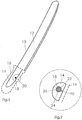
- Fig. 1 shows a knife 10 according to the invention, consisting of a metallic blade 12, a metallic Erl 14 with an opening 18 and a plastic handle 16. The latter is indicated only by dashed lines to allow the view of the opening 18.
- the opening 18 has an outwardly leading slot 20 and in the opening is an RFID chip with a coupling loop (detail Fig. 2 ) arranged.
- the metallic blade 12 and the metallic Erl 14 emitters of an asymmetrically inductively powered electric antenna.
- the metal immediately surrounding the opening 18 forms a coupling winding for the radiator and is simultaneously integrated into the radiator.
- the outwardly directed from the opening 18 slot 20 is necessary so that a coupling winding and no short-circuit winding is formed.
- Fig. 2 shows as a detail Fig. 1 an enlarged view of an opening 18 with the RFIF chip 22, the coupling loop 24 and the slot 20.
- the RFID chip 22 with the coupling loop 24 is embedded in a potting compound 26 and represents a prefabricated component whose outer dimensions correspond to the diameter and the thickness of the Erl 14. This component is used before injection molding of the plastic handle 16 in the opening 18 and jammed there.
- Fig. 3 shows a schematic representation of a system for input and output and for cleaning and maintenance of tools.
- the system comprises an input and output station 28 and a cleaning and maintenance station 32 for tools 10, each equipped with a reading device 34, 36, 38.
- a user receives a tool 10, z. As a knife, at an input and output station 28. There Ident data of the tool 10 and possibly the user are detected. After a maximum useful life of the tool 10, the user receives a signal that informs him of the end of the service life and causes him to return the used tool at an input and output station 28.
- cleaning and / or maintenance is then carried out in a cleaning or service station 32 before the tool 10, if possible, is returned to the use cycle.
- a cleaning and / or sharpening tool can be preset in the machining parameters via an identification of the type and type of the hand tool 10.
Landscapes
- Life Sciences & Earth Sciences (AREA)
- Engineering & Computer Science (AREA)
- Food Science & Technology (AREA)
- Forests & Forestry (AREA)
- Mechanical Engineering (AREA)
- Wood Science & Technology (AREA)
- Zoology (AREA)
- Machine Tool Sensing Apparatuses (AREA)
- Injection Moulding Of Plastics Or The Like (AREA)
Description
- Die Erfindung betrifft ein Handwerkzeug nach dem Oberbegriff des Anspruchs 1.
- Handwerkzeuge im gewerblichen industriellen und medizinischen Bereich unterliegen Anforderungen wie Registrierung bei Aus- und Abgabe, Erfassung der Vollständigkeit, Erfassung der Einsatzzeit. So werden z. B. in fleischverarbeitenden Betrieben Entbeinungsmesser eingesetzt, die nach einer festgelegten Benutzungsdauer gereinigt werden müssen, damit eine Vermehrung und Weitergabe von Keimen verhindert wird.
- Zur sicheren, genauen und schnellen Erfassung der Handwerkzeuge wäre die Nutzung von berührungslos lesbaren RFID-Chips an den Handwerkzeugen und deren Registrierung mittels Lesegeräten sinnvoll.
- Um eine ausreichende Lesereichweite der RFID-Chips zu erhalten, ist eine mit dem Chip gekoppelte Antenne notwendig. Eine in einen Kunststoffgriff des Handwerkzeugs eingelassene Antenne würde wegen der Nachbarschaft zu metallischen Teilen stark gedämpft werden. Bei ausschließlich aus Metall bestehen Handwerkzeugen, z. B. medizinischen Instrumenten ist das Problem noch gravierender.
- Aus der
WO 01/42991 A1 - Der Erfindung liegt die Aufgabe zugrunde, ein Handwerkzeug derart mit einem RFID-Chip zu kombinieren, dass eine hohe Lesereichweite und damit eine sichere Identifizierung erzielt wird.
- Diese Aufgabe wird durch ein Handwerkzeug nach Anspruch gelöst.
- Weiterbildungen und vorteilhafte Ausgestaltungen ergeben sich aus den Unteransprüchen.
- Bei der erfindungsgemäßen Lösung ist der metallische Teil des Handwerkzeugs selbst Antenne, mit der der RFID-Chip mittels seiner Koppelschleife in einer Öffnung mit einem nach außen geführten Schlitz im metallischen Teil gekoppelt ist. Wegen der induktiven Kopplung an der Öffnung ist an dieser Stelle das "kalte" Ende der Antenne gebildet. Kapazitive Einflüsse auf die Antenne durch die Hand eines Nutzers an dieser Stelle sind daher minimal.
- Sofern das Handwerkzeug mit einem angespritzten Kunststoffhandgriff versehen wird, sind keine Änderungen am Werkzeug zum Spritzen des Kunststoffhandgriffs nötig. Außerdem ist der RFID-Chip mit der Koppelspule während des Spritzvorgangs keiner hohen Temperatur des flüssigen Kunststoffes ausgesetzt, da die Wärme durch den metallischen Teil abgeleitet werden kann.
- Gemäß einer Weiterbildung ist der RFID-Chip mit der Koppelschleife in eine Vergussmasse eingebettet und in die Öffnung eingeklemmt.
- Dadurch bleibt der RFID-Chip mit der Koppelschleife nach dem Einsetzen in die Öffnung definiert positioniert und ist bei nachfolgenden Herstellungsschritten gegen eine mögliche Verlagerung resistent. Zudem bildet die Vergussmasse eine Wärmeisolierung für den RFID-Chip und die Koppelschleife beim Anspritzen des Kunststoffgriffs und überbrückt damit die Zeit zwischen dem Anspritzen mit flüssigem Kunststoff und dessen Abkühlen.
- Vorzugsweise umschließt der Kunststoffgriff die Öffnung und den in der Öffnung angeordneten RFID-Chip mit der Koppelschleife.
- Dadurch ist der RFID-Chip mit der Koppelschleife beim fertigen Handwerkzeug zusätzlich durch den Kunststoffgriff geschützt und von außen unzugänglich. Er ist somit weder mechanischen Einflüssen bei der Handhabung des Handwerkzeugs ausgesetzt, noch chemischen Einflüssen bei der Reinigung.
- Angaben über Art und Typs des Handwerkzeugs können im RFID-Chip codiert oder uncodiert durch Beschreiben gespeichert sein.
- Dadurch kann das Handwerkzeug unabhängig von einer zentralen Historiespeicherung seine spezifischen Daten bei sich tragen, so dass diese von jedem beliebigen Lesegerät abgefragt werden können.
- Ferner kann die Gebrauchsdauer erfasst werden.
- Dadurch ist es möglich, gebrauchte Werkzeuge rechtzeitig aus dem Produktions- oder Nutzungsprozess zu entziehen, um Verunreinigungen oder Verschleiß zu vermeiden.
- Bearbeitungs- und Wartungsvorgänge, wie Reinigen, Schärfen können erfasst und gespeichert werden.
- Durch Erfassen der Historie von Bearbeitungs- und Wartungsvorgänge, wie Reinigen, Schärfen können sämtliche Vorgänge ausgewertet werden, die Aufschluss über Brauchbarkeit und Lebensdauer des Werkzeugs liefern.
- Bei Überschreiten von Grenzwerten der Anzahl der Bearbeitungs- und Wartungsvorgänge kann der Nutzer gewarnt oder das Werkzeug aus dem Nutzungskreislauf entfernt werden.
- Dadurch wir sichergestellt, dass ungeeignete Werkzeuge nicht mehr in den Produktions- oder Nutzungsprozess gelangen.
- Über eine Identifizierung von Art und Typs des Handwerkzeugs kann ein Reinigungs- und/oder Schärfwerkzeug voreingestellt werden.
- Dies erleichtert wesentlich die Handhabung des Werkzeugs nach Gebrauch und ermöglicht, die Maschineneinstellungen für nachfolgende Reinigungs- und Wartungsarbeiten automatisch und bedarfsgerecht vorzunehmen.
- Nachfolgend wird die Erfindung anhand eines Ausführungsbeispiels erläutert, das in der Zeichnung dargestellt ist.
- In der Zeichnung zeigen:
- Fig. 1
- ein als Messer ausgebildetes Handwerkzeug nach der Erfindung,
- Fig. 2
- als Detail aus
Fig. 1 eine vergrößerte Darstellung einer Öffnung mit dem RFIF-Chip und der Koppelschleife und - Fig. 3
- eine schematische Darstellung einer Anlage zur Ein- und Ausgabe sowie zur Reinigung und Wartung von Werkzeugen.
-
Fig. 1 zeigt ein Messer 10 nach der Erfindung, bestehend aus einer metallischen Klinge 12, einem metallischen Erl 14 mit einer Öffnung 18 und einem Kunststoffgriff 16. Letzterer ist nur gestrichelt angedeutet, um die Sicht auf die Öffnung 18 zu ermöglichen. Die Öffnung 18 weist einen nach außen führenden Schlitz 20 auf und in der Öffnung ist ein RFID-Chip mit einer Koppelschleife (DetailFig. 2 ) angeordnet. - Die metallische Klinge 12 und das metallischen Erl 14 sind erfindungsgemäß Strahler einer asymmetrisch induktiv gespeisten elektrischen Antenne. Das die Öffnung 18 unmittelbar umgebende Metall bildet eine Koppelwindung für die Strahler und ist gleichzeitig in die Strahler integriert. Der von der Öffnung 18 nach außen geführte Schlitz 20 ist nötig, damit eine Koppelwindung und keine Kurzschlusswindung entsteht.
-
Fig. 2 zeigt als Detail ausFig. 1 eine vergrößerte Darstellung einer Öffnung 18 mit dem RFIF-Chip 22, der Koppelschleife 24 und dem Schlitz 20. Der RFID-Chip 22 mit der Koppelschleife 24 ist in eine Vergussmasse 26 eingebettet und stellt ein vorgefertigtes Bauteil dar, dessen äußere Abmessungen dem Durchmeser und der Dicke des Erl 14 entsprechen. Dieses Bauteil wird vor Anspritzen des Kunststoffgriffes 16 in die Öffnung 18 eingesetzt und verklemmt sich dort. -
Fig. 3 zeigt eine schematische Darstellung einer Anlage zur Ein- und Ausgabe sowie zur Reinigung und Wartung von Werkzeugen., - Die Anlage umfasst eine Ein- und Ausgabestation 28 sowie eine Reinigungs- 30 und Wartungsstation 32 für Werkzeuge 10, jeweils ausgestattet mit einem Lesegerät 34, 36, 38.
- Ein Nutzer erhält ein Werkzeug 10, z. B. ein Messer, an einer Ein- und Ausgabestation 28. Dort werden Identdaten des Werkzeugs 10 sowie eventuell des Nutzers erfasst. Der Nutzer empfängt nach einer maximalen Nutzungsdauer des Werkzeugs 10 ein Signal, dass ihm das das Ende der Nutzungsdauer mitteilt und ihn veranlasst, das verbrauchte Werkzeug an der einer Ein- und Ausgabestation 28 zurückzugeben.
- Je nach Art des Werkzeugs 10 wird anschließend eine Reinigung und/oder Wartung in einer Reinigungs- 30, oder Wartungsstation 32 durchgeführt, ehe das Werkzeug 10, sofern möglich, in den Nutzungskreislauf zurückgeführt wird.
- Beim Erfassen des Werkzeugs 10 an der Ein- und Ausgabestation 28 sowie der Reinigungs- 30, oder Wartungsstation 32 werden Angaben über Art und Typs des Handwerkzeugs 10 sowie Gebrauchsdauer in einem Stationsspeicher und im RFID-Chip 22 codiert oder uncodiert durch Beschreiben gespeichert. Weiterhin werden Einsatzzeiten sowie Bearbeitungs- und Wartungsvorgänge, wie Reinigen, Schärfen erfasst und gespeichert. Bei Überschreiten von zulässigen Grenzwerten der Einsatzzeiten sowie der Anzahl der zulässigen Bearbeitungs- und Wartungsvorgänge kann der Nutzer gewarnt werden oder das Werkzeug aus dem Nutzungskreislauf entfernt werden.
- Falls Bearbeitungs- und Wartungsvorgänge sinnvoll sind und einen erneuten Einsatz des Werkzeugs versprechen, kann über eine Identifizierung von Art und Typs des Handwerkzeugs 10 ein Reinigungs- und/oder Schärfwerkzeug in den Bearbeitungsparametern voreingestellt werden.
Claims (5)
- Handwerkzeug, bestehend aus wenigstens einem metallischen Teil, wobei der metallische Teil (14) eine Öffnung (18) aufweist, in der ein RFID-Chip (22) angeordnet ist, dadurch gekennzeichnet, dass der metallische Teil (14) eine Antenne ist, mit der der RFID-Chip (22) über eine Koppelschleife (24) induktiv gekoppelt ist, wobei die Öffnung (18) im metallischen Teil (14) einen nach außen geführten Schlitz (20) aufweist und in der Öffnung (18) zusätzlich die Koppelschleife (24) angeordnet ist, wodurch der metallische Teil (14) des Handwerkzeugs selbst Antenne ist.
- Handwerkzeug nach Anspruch 1, dadurch gekennzeichnet, dass der RFID-Chip (22) mit der Koppelschleife (24) in eine Vergussmasse (26) eingebettet ist und in die Öffnung (18) eingeklemmt ist.
- Handwerkzeug nach Anspruch 2, dadurch gekennzeichnet, dass ein Kunststoffgriff (16) den metallischen Teil (14) mit der Öffnung (18) und den in der Öffnung (18) angeordneten RFID-Chip (22) mit der Koppelschleife (24) umschließt.
- Handwerkzeug nach einem der Ansprüche 1 bis 3, welches als Messer aus einer metallischen Klinge (12) und einem metallischen Erl (14) ausgebildet ist, dadurch gekennzeichnet, dass die Öffnung (18) mit dem nach außen geführten Schlitz (20) im Erl (14) angeordnet ist.
- Handwerkzeug nach Anspruch 4, dadurch gekennzeichnet, dass der Erl (14) mit der Öffnung (18) mit dem nach außen geführten Schlitz (20) sowie der in der Öffnung (18) angeordnete RFID-Chip (22) mit der Koppelschleife (24) von einem Kunststoffgriff (16) umschlossen ist.
Applications Claiming Priority (2)
| Application Number | Priority Date | Filing Date | Title |
|---|---|---|---|
| DE200810026678 DE102008026678B4 (de) | 2008-06-04 | 2008-06-04 | Handwerkzeug |
| PCT/DE2009/000744 WO2009146677A1 (de) | 2008-06-04 | 2009-05-28 | Handwerkzeug |
Publications (2)
| Publication Number | Publication Date |
|---|---|
| EP2280609A1 EP2280609A1 (de) | 2011-02-09 |
| EP2280609B1 true EP2280609B1 (de) | 2018-08-08 |
Family
ID=40996580
Family Applications (1)
| Application Number | Title | Priority Date | Filing Date |
|---|---|---|---|
| EP09757111.1A Active EP2280609B1 (de) | 2008-06-04 | 2009-05-28 | Handwerkzeug |
Country Status (4)
| Country | Link |
|---|---|
| EP (1) | EP2280609B1 (de) |
| DE (1) | DE102008026678B4 (de) |
| ES (1) | ES2694045T3 (de) |
| WO (1) | WO2009146677A1 (de) |
Cited By (3)
| Publication number | Priority date | Publication date | Assignee | Title |
|---|---|---|---|---|
| WO2023014385A1 (en) * | 2021-08-02 | 2023-02-09 | Dexter-Russell, Inc. | A tool having a detectable wireless marker or tag |
| WO2024215388A1 (en) * | 2021-08-02 | 2024-10-17 | Dexter-Russell, Inc. | A tool having a detectable wireless marker or tag |
| US12579395B2 (en) | 2021-08-02 | 2026-03-17 | Dexter-Russell, Inc. | Tool having a detectable wireless marker or tag |
Families Citing this family (5)
| Publication number | Priority date | Publication date | Assignee | Title |
|---|---|---|---|---|
| DE102010022967A1 (de) * | 2010-06-08 | 2011-12-08 | Johannes Giesser Messerfabrik Gmbh | System und Verfahren zur Überwachung von Werkzeugen |
| FI127821B (en) | 2013-05-17 | 2019-03-15 | Lm Instr Oy | Medical or dental instrument and method of its manufacture |
| DE102013219875B4 (de) | 2013-10-01 | 2019-10-17 | Fried. Dick Gmbh & Co. Kg | Messer mit einem am Erl angeordneten RFID-Transponder |
| PL3809330T3 (pl) * | 2019-10-17 | 2024-09-16 | Ivo Cutelarias, S.A. | Artykuł sztućcowy z pasywnym identyfikatorem uhf |
| KR102539605B1 (ko) * | 2022-10-14 | 2023-06-05 | 대원미트주식회사 | 뼈 발골용 칼 |
Family Cites Families (4)
| Publication number | Priority date | Publication date | Assignee | Title |
|---|---|---|---|---|
| AUPQ453499A0 (en) * | 1999-12-08 | 2000-01-06 | Herbert Mcivor Holdings Pty Ltd | A system and method for automatically logging article use and an article adapted for such |
| DE102004022290B4 (de) * | 2004-05-04 | 2009-08-20 | Friedr. Dick Gmbh & Co. Kg | Messer und Messerregistriersystem |
| DE102006012070A1 (de) * | 2006-03-16 | 2007-09-20 | Zwilling J. A. Henckels Ag | Schneidwerkzeug, insbesondere Messer |
| DE102006032150B4 (de) * | 2006-07-12 | 2009-08-06 | Friedr. Dick Gmbh & Co. Kg | Messer und Verfahren zu dessen Herstellung |
-
2008
- 2008-06-04 DE DE200810026678 patent/DE102008026678B4/de not_active Expired - Fee Related
-
2009
- 2009-05-28 ES ES09757111.1T patent/ES2694045T3/es active Active
- 2009-05-28 EP EP09757111.1A patent/EP2280609B1/de active Active
- 2009-05-28 WO PCT/DE2009/000744 patent/WO2009146677A1/de not_active Ceased
Non-Patent Citations (1)
| Title |
|---|
| None * |
Cited By (3)
| Publication number | Priority date | Publication date | Assignee | Title |
|---|---|---|---|---|
| WO2023014385A1 (en) * | 2021-08-02 | 2023-02-09 | Dexter-Russell, Inc. | A tool having a detectable wireless marker or tag |
| WO2024215388A1 (en) * | 2021-08-02 | 2024-10-17 | Dexter-Russell, Inc. | A tool having a detectable wireless marker or tag |
| US12579395B2 (en) | 2021-08-02 | 2026-03-17 | Dexter-Russell, Inc. | Tool having a detectable wireless marker or tag |
Also Published As
| Publication number | Publication date |
|---|---|
| DE102008026678B4 (de) | 2014-12-04 |
| EP2280609A1 (de) | 2011-02-09 |
| WO2009146677A1 (de) | 2009-12-10 |
| DE102008026678A1 (de) | 2009-12-10 |
| ES2694045T3 (es) | 2018-12-17 |
Similar Documents
| Publication | Publication Date | Title |
|---|---|---|
| DE102008026678B4 (de) | Handwerkzeug | |
| EP3639942B2 (de) | Pressmaschine mit sensorsystem zur automatisierten erkennung einer pressbackenanordnung | |
| EP1130377B1 (de) | Vorrichtung zur automatischen Identifikation und Bearbeitung von Objekten | |
| EP3639941B1 (de) | Pressmaschine mit sensorsystem zur werkstück-identifikation | |
| DE102006046759B4 (de) | Verfahren zur Erhöhung der Sicherheit beim Betrieb eines Roboters | |
| EP4291962A1 (de) | Verfahren zur rückverfolgung von schmiedeteilen über den gesamten herstellungsprozess, insbesondere vom schmiedeprozess, über sandstrahlen und warmbehandlung bis zur mechanischen bearbeitung | |
| WO2008006342A1 (de) | Messer und verfahren zu dessen herstellung | |
| EP3459897B1 (de) | Bedienvorrichtung für eine handhabungsvorrichtung | |
| DE202013100697U1 (de) | Vorrichtung zur Kontrolle der Beladung eines Service-Fahrzeugs | |
| DE19840785C2 (de) | Verfahren zur Ausrüstung eines Gegenstandes mit Informationsdaten | |
| DE2943622A1 (de) | Verfahren und vorrichtung zum codieren und decodieren von teilen | |
| EP3421169B1 (de) | Schutzglas mit einem transponder und einbauhilfe ; zugehörige schutzglaskassette und laserwerkzeug | |
| EP2395405B1 (de) | System und Verfahren zur Überwachung von Werkzeugen | |
| EP2147414B1 (de) | Messstellenkennzeichnung zur automatischen messstellenerkennung in einem system zur zustandsüberwachung | |
| EP1744943B1 (de) | Messer und messerregistriersystem | |
| EP3317005B1 (de) | Dispergiervorrichtung | |
| DE102008005986A1 (de) | Sicherheitseinrichtung für Werkzeugmaschinen | |
| DE102006039207B3 (de) | System sowie Verfahren zur Organisation von zu bearbeitenden Werkstücken | |
| DE3607771A1 (de) | Werkzeughalter mit datentraeger | |
| DE10323168A1 (de) | Elektronisches Bauteil mit einem Kennzeichnungselement | |
| DE19505513C2 (de) | Verfahren zur Einzelstückverfolgung | |
| DE20209915U1 (de) | Transponderbasierte Vorrichtung zur Identifikation von Radsätzen | |
| DE102022115563B3 (de) | Entnahmesystem und Verfahren zum Betrieb eines Entnahmesystems | |
| AT396417B (de) | Vorrichtung zur übernahme von milch od. dgl. | |
| WO2007025997A1 (de) | Rohling für ein zahnersatzteil mit für eine bearbeitung relevanten informationen und bearbeitungsvorrichtung und verfahren für diesen |
Legal Events
| Date | Code | Title | Description |
|---|---|---|---|
| PUAI | Public reference made under article 153(3) epc to a published international application that has entered the european phase |
Free format text: ORIGINAL CODE: 0009012 |
|
| 17P | Request for examination filed |
Effective date: 20101008 |
|
| AK | Designated contracting states |
Kind code of ref document: A1 Designated state(s): AT BE BG CH CY CZ DE DK EE ES FI FR GB GR HR HU IE IS IT LI LT LU LV MC MK MT NL NO PL PT RO SE SI SK TR |
|
| AX | Request for extension of the european patent |
Extension state: AL BA RS |
|
| DAX | Request for extension of the european patent (deleted) | ||
| 17Q | First examination report despatched |
Effective date: 20141126 |
|
| REG | Reference to a national code |
Ref country code: DE Ref legal event code: R079 Ref document number: 502009015167 Country of ref document: DE Free format text: PREVIOUS MAIN CLASS: A22B0003100000 Ipc: B26B0003000000 |
|
| GRAP | Despatch of communication of intention to grant a patent |
Free format text: ORIGINAL CODE: EPIDOSNIGR1 |
|
| STAA | Information on the status of an ep patent application or granted ep patent |
Free format text: STATUS: GRANT OF PATENT IS INTENDED |
|
| INTG | Intention to grant announced |
Effective date: 20180507 |
|
| RIC1 | Information provided on ipc code assigned before grant |
Ipc: A22B 5/00 20060101ALI20180420BHEP Ipc: A22C 17/00 20060101ALI20180420BHEP Ipc: B26B 3/00 20060101AFI20180420BHEP |
|
| GRAS | Grant fee paid |
Free format text: ORIGINAL CODE: EPIDOSNIGR3 |
|
| GRAA | (expected) grant |
Free format text: ORIGINAL CODE: 0009210 |
|
| STAA | Information on the status of an ep patent application or granted ep patent |
Free format text: STATUS: THE PATENT HAS BEEN GRANTED |
|
| AK | Designated contracting states |
Kind code of ref document: B1 Designated state(s): AT BE BG CH CY CZ DE DK EE ES FI FR GB GR HR HU IE IS IT LI LT LU LV MC MK MT NL NO PL PT RO SE SI SK TR |
|
| REG | Reference to a national code |
Ref country code: GB Ref legal event code: FG4D Free format text: NOT ENGLISH |
|
| REG | Reference to a national code |
Ref country code: CH Ref legal event code: EP Ref country code: AT Ref legal event code: REF Ref document number: 1026465 Country of ref document: AT Kind code of ref document: T Effective date: 20180815 |
|
| REG | Reference to a national code |
Ref country code: IE Ref legal event code: FG4D Free format text: LANGUAGE OF EP DOCUMENT: GERMAN |
|
| REG | Reference to a national code |
Ref country code: DE Ref legal event code: R096 Ref document number: 502009015167 Country of ref document: DE |
|
| REG | Reference to a national code |
Ref country code: NL Ref legal event code: MP Effective date: 20180808 |
|
| REG | Reference to a national code |
Ref country code: ES Ref legal event code: FG2A Ref document number: 2694045 Country of ref document: ES Kind code of ref document: T3 Effective date: 20181217 |
|
| REG | Reference to a national code |
Ref country code: LT Ref legal event code: MG4D |
|
| PG25 | Lapsed in a contracting state [announced via postgrant information from national office to epo] |
Ref country code: IS Free format text: LAPSE BECAUSE OF FAILURE TO SUBMIT A TRANSLATION OF THE DESCRIPTION OR TO PAY THE FEE WITHIN THE PRESCRIBED TIME-LIMIT Effective date: 20181208 Ref country code: PL Free format text: LAPSE BECAUSE OF FAILURE TO SUBMIT A TRANSLATION OF THE DESCRIPTION OR TO PAY THE FEE WITHIN THE PRESCRIBED TIME-LIMIT Effective date: 20180808 Ref country code: GR Free format text: LAPSE BECAUSE OF FAILURE TO SUBMIT A TRANSLATION OF THE DESCRIPTION OR TO PAY THE FEE WITHIN THE PRESCRIBED TIME-LIMIT Effective date: 20181109 Ref country code: NO Free format text: LAPSE BECAUSE OF FAILURE TO SUBMIT A TRANSLATION OF THE DESCRIPTION OR TO PAY THE FEE WITHIN THE PRESCRIBED TIME-LIMIT Effective date: 20181108 Ref country code: SE Free format text: LAPSE BECAUSE OF FAILURE TO SUBMIT A TRANSLATION OF THE DESCRIPTION OR TO PAY THE FEE WITHIN THE PRESCRIBED TIME-LIMIT Effective date: 20180808 Ref country code: FI Free format text: LAPSE BECAUSE OF FAILURE TO SUBMIT A TRANSLATION OF THE DESCRIPTION OR TO PAY THE FEE WITHIN THE PRESCRIBED TIME-LIMIT Effective date: 20180808 Ref country code: BG Free format text: LAPSE BECAUSE OF FAILURE TO SUBMIT A TRANSLATION OF THE DESCRIPTION OR TO PAY THE FEE WITHIN THE PRESCRIBED TIME-LIMIT Effective date: 20181108 Ref country code: NL Free format text: LAPSE BECAUSE OF FAILURE TO SUBMIT A TRANSLATION OF THE DESCRIPTION OR TO PAY THE FEE WITHIN THE PRESCRIBED TIME-LIMIT Effective date: 20180808 Ref country code: LT Free format text: LAPSE BECAUSE OF FAILURE TO SUBMIT A TRANSLATION OF THE DESCRIPTION OR TO PAY THE FEE WITHIN THE PRESCRIBED TIME-LIMIT Effective date: 20180808 |
|
| PG25 | Lapsed in a contracting state [announced via postgrant information from national office to epo] |
Ref country code: HR Free format text: LAPSE BECAUSE OF FAILURE TO SUBMIT A TRANSLATION OF THE DESCRIPTION OR TO PAY THE FEE WITHIN THE PRESCRIBED TIME-LIMIT Effective date: 20180808 Ref country code: LV Free format text: LAPSE BECAUSE OF FAILURE TO SUBMIT A TRANSLATION OF THE DESCRIPTION OR TO PAY THE FEE WITHIN THE PRESCRIBED TIME-LIMIT Effective date: 20180808 |
|
| PG25 | Lapsed in a contracting state [announced via postgrant information from national office to epo] |
Ref country code: CZ Free format text: LAPSE BECAUSE OF FAILURE TO SUBMIT A TRANSLATION OF THE DESCRIPTION OR TO PAY THE FEE WITHIN THE PRESCRIBED TIME-LIMIT Effective date: 20180808 Ref country code: IT Free format text: LAPSE BECAUSE OF FAILURE TO SUBMIT A TRANSLATION OF THE DESCRIPTION OR TO PAY THE FEE WITHIN THE PRESCRIBED TIME-LIMIT Effective date: 20180808 Ref country code: RO Free format text: LAPSE BECAUSE OF FAILURE TO SUBMIT A TRANSLATION OF THE DESCRIPTION OR TO PAY THE FEE WITHIN THE PRESCRIBED TIME-LIMIT Effective date: 20180808 Ref country code: EE Free format text: LAPSE BECAUSE OF FAILURE TO SUBMIT A TRANSLATION OF THE DESCRIPTION OR TO PAY THE FEE WITHIN THE PRESCRIBED TIME-LIMIT Effective date: 20180808 |
|
| REG | Reference to a national code |
Ref country code: DE Ref legal event code: R097 Ref document number: 502009015167 Country of ref document: DE |
|
| PG25 | Lapsed in a contracting state [announced via postgrant information from national office to epo] |
Ref country code: DK Free format text: LAPSE BECAUSE OF FAILURE TO SUBMIT A TRANSLATION OF THE DESCRIPTION OR TO PAY THE FEE WITHIN THE PRESCRIBED TIME-LIMIT Effective date: 20180808 Ref country code: SK Free format text: LAPSE BECAUSE OF FAILURE TO SUBMIT A TRANSLATION OF THE DESCRIPTION OR TO PAY THE FEE WITHIN THE PRESCRIBED TIME-LIMIT Effective date: 20180808 |
|
| PLBE | No opposition filed within time limit |
Free format text: ORIGINAL CODE: 0009261 |
|
| STAA | Information on the status of an ep patent application or granted ep patent |
Free format text: STATUS: NO OPPOSITION FILED WITHIN TIME LIMIT |
|
| 26N | No opposition filed |
Effective date: 20190509 |
|
| PG25 | Lapsed in a contracting state [announced via postgrant information from national office to epo] |
Ref country code: SI Free format text: LAPSE BECAUSE OF FAILURE TO SUBMIT A TRANSLATION OF THE DESCRIPTION OR TO PAY THE FEE WITHIN THE PRESCRIBED TIME-LIMIT Effective date: 20180808 |
|
| REG | Reference to a national code |
Ref country code: CH Ref legal event code: PL |
|
| PG25 | Lapsed in a contracting state [announced via postgrant information from national office to epo] |
Ref country code: CH Free format text: LAPSE BECAUSE OF NON-PAYMENT OF DUE FEES Effective date: 20190531 Ref country code: MC Free format text: LAPSE BECAUSE OF FAILURE TO SUBMIT A TRANSLATION OF THE DESCRIPTION OR TO PAY THE FEE WITHIN THE PRESCRIBED TIME-LIMIT Effective date: 20180808 Ref country code: LI Free format text: LAPSE BECAUSE OF NON-PAYMENT OF DUE FEES Effective date: 20190531 |
|
| REG | Reference to a national code |
Ref country code: BE Ref legal event code: MM Effective date: 20190531 |
|
| PG25 | Lapsed in a contracting state [announced via postgrant information from national office to epo] |
Ref country code: LU Free format text: LAPSE BECAUSE OF NON-PAYMENT OF DUE FEES Effective date: 20190528 |
|
| PG25 | Lapsed in a contracting state [announced via postgrant information from national office to epo] |
Ref country code: TR Free format text: LAPSE BECAUSE OF FAILURE TO SUBMIT A TRANSLATION OF THE DESCRIPTION OR TO PAY THE FEE WITHIN THE PRESCRIBED TIME-LIMIT Effective date: 20180808 |
|
| PG25 | Lapsed in a contracting state [announced via postgrant information from national office to epo] |
Ref country code: IE Free format text: LAPSE BECAUSE OF NON-PAYMENT OF DUE FEES Effective date: 20190528 |
|
| PG25 | Lapsed in a contracting state [announced via postgrant information from national office to epo] |
Ref country code: BE Free format text: LAPSE BECAUSE OF NON-PAYMENT OF DUE FEES Effective date: 20190531 |
|
| PG25 | Lapsed in a contracting state [announced via postgrant information from national office to epo] |
Ref country code: PT Free format text: LAPSE BECAUSE OF FAILURE TO SUBMIT A TRANSLATION OF THE DESCRIPTION OR TO PAY THE FEE WITHIN THE PRESCRIBED TIME-LIMIT Effective date: 20181208 |
|
| REG | Reference to a national code |
Ref country code: AT Ref legal event code: MM01 Ref document number: 1026465 Country of ref document: AT Kind code of ref document: T Effective date: 20190528 |
|
| PG25 | Lapsed in a contracting state [announced via postgrant information from national office to epo] |
Ref country code: AT Free format text: LAPSE BECAUSE OF NON-PAYMENT OF DUE FEES Effective date: 20190528 |
|
| PG25 | Lapsed in a contracting state [announced via postgrant information from national office to epo] |
Ref country code: CY Free format text: LAPSE BECAUSE OF FAILURE TO SUBMIT A TRANSLATION OF THE DESCRIPTION OR TO PAY THE FEE WITHIN THE PRESCRIBED TIME-LIMIT Effective date: 20180808 |
|
| PG25 | Lapsed in a contracting state [announced via postgrant information from national office to epo] |
Ref country code: MT Free format text: LAPSE BECAUSE OF FAILURE TO SUBMIT A TRANSLATION OF THE DESCRIPTION OR TO PAY THE FEE WITHIN THE PRESCRIBED TIME-LIMIT Effective date: 20180808 Ref country code: HU Free format text: LAPSE BECAUSE OF FAILURE TO SUBMIT A TRANSLATION OF THE DESCRIPTION OR TO PAY THE FEE WITHIN THE PRESCRIBED TIME-LIMIT; INVALID AB INITIO Effective date: 20090528 |
|
| PG25 | Lapsed in a contracting state [announced via postgrant information from national office to epo] |
Ref country code: MK Free format text: LAPSE BECAUSE OF FAILURE TO SUBMIT A TRANSLATION OF THE DESCRIPTION OR TO PAY THE FEE WITHIN THE PRESCRIBED TIME-LIMIT Effective date: 20180808 |
|
| P01 | Opt-out of the competence of the unified patent court (upc) registered |
Effective date: 20230530 |
|
| PGFP | Annual fee paid to national office [announced via postgrant information from national office to epo] |
Ref country code: DE Payment date: 20250516 Year of fee payment: 17 |
|
| PGFP | Annual fee paid to national office [announced via postgrant information from national office to epo] |
Ref country code: GB Payment date: 20250522 Year of fee payment: 17 Ref country code: ES Payment date: 20250616 Year of fee payment: 17 |
|
| PGFP | Annual fee paid to national office [announced via postgrant information from national office to epo] |
Ref country code: FR Payment date: 20250523 Year of fee payment: 17 |