EP2279803B2 - Transporteur hélicoïdal - Google Patents
Transporteur hélicoïdal Download PDFInfo
- Publication number
- EP2279803B2 EP2279803B2 EP10006871.7A EP10006871A EP2279803B2 EP 2279803 B2 EP2279803 B2 EP 2279803B2 EP 10006871 A EP10006871 A EP 10006871A EP 2279803 B2 EP2279803 B2 EP 2279803B2
- Authority
- EP
- European Patent Office
- Prior art keywords
- container
- transport
- spiral conveyor
- conveyor according
- support ring
- Prior art date
- Legal status (The legal status is an assumption and is not a legal conclusion. Google has not performed a legal analysis and makes no representation as to the accuracy of the status listed.)
- Active
Links
- 238000013461 design Methods 0.000 claims description 10
- 238000004140 cleaning Methods 0.000 claims description 9
- 238000001035 drying Methods 0.000 claims description 4
- 230000000694 effects Effects 0.000 claims description 2
- 230000001360 synchronised effect Effects 0.000 claims description 2
- 238000007664 blowing Methods 0.000 description 6
- 230000002093 peripheral effect Effects 0.000 description 5
- 238000005406 washing Methods 0.000 description 5
- 239000007788 liquid Substances 0.000 description 4
- 238000005507 spraying Methods 0.000 description 3
- 238000003780 insertion Methods 0.000 description 2
- 230000037431 insertion Effects 0.000 description 2
- 239000007921 spray Substances 0.000 description 2
- 235000013361 beverage Nutrition 0.000 description 1
- 239000012530 fluid Substances 0.000 description 1
- 238000002347 injection Methods 0.000 description 1
- 239000007924 injection Substances 0.000 description 1
- 238000009434 installation Methods 0.000 description 1
- 238000012986 modification Methods 0.000 description 1
- 230000004048 modification Effects 0.000 description 1
- 238000012549 training Methods 0.000 description 1
- 238000012546 transfer Methods 0.000 description 1
- 230000007704 transition Effects 0.000 description 1
Images


Classifications
-
- B—PERFORMING OPERATIONS; TRANSPORTING
- B65—CONVEYING; PACKING; STORING; HANDLING THIN OR FILAMENTARY MATERIAL
- B65G—TRANSPORT OR STORAGE DEVICES, e.g. CONVEYORS FOR LOADING OR TIPPING, SHOP CONVEYOR SYSTEMS OR PNEUMATIC TUBE CONVEYORS
- B65G11/00—Chutes
- B65G11/06—Chutes of helical or spiral form
- B65G11/063—Chutes of helical or spiral form for articles
-
- B—PERFORMING OPERATIONS; TRANSPORTING
- B65—CONVEYING; PACKING; STORING; HANDLING THIN OR FILAMENTARY MATERIAL
- B65B—MACHINES, APPARATUS OR DEVICES FOR, OR METHODS OF, PACKAGING ARTICLES OR MATERIALS; UNPACKING
- B65B55/00—Preserving, protecting or purifying packages or package contents in association with packaging
- B65B55/24—Cleaning of, or removing dust from, containers, wrappers, or packaging ; Preventing of fouling
Definitions
- the invention relates to a spiral conveyor according to the preamble of claim 1.
- Spiral conveyors of this type are known ( DE 101 16 854 A1 ).
- a disadvantage of these known spiral conveyors is that the arrangement of the at least one driver not rotating, in particular stationary functional elements in the space enclosed by the helical transport path space as well as the supply of any supply lines in this room are possible only with relatively large design effort.
- the object of the invention is to show a spiral conveyor, which avoids this disadvantage.
- a spiral conveyor according to the patent claim 1 is formed.
- the spiral conveyor is part of a device for cleaning the container. Due to the special design of the device or the spiral conveyor it is u.a. possible to arrange nozzles for spraying the container easily even within the space surrounding the helical transport path stationary and to connect via simple connecting lines, in particular via connecting lines without rotary distributor or rotary joints with that source that provides the treatment and / or cleaning fluid ,
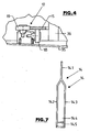
- Containers within the meaning of the invention are containers, in particular on their outer contour cubic or cuboid containers, which are used for storage and / or transport of products, such. Transport and / or storage boxes, beverage or bottle crates etc.
- spiral conveyor is used to convey containers or containers 2 in the form of boxes, for example in the form of transport boxes, and crates on a vertical machine axis MA enclosing helical and generally designated 3 in the figures transport route.
- the containers 2, which have the usual shape in transport boxes or crates, are fed to the spiral conveyor 1 or its transport path from an outer transporter, not shown, in a transport direction A via a lower container inlet 4.
- the containers 2 are, after they have passed the transport path 3 in the transport direction A, forwarded by the transport path 3 via an upper container outlet 5 in the transport direction A at an outer conveyor not shown for further use and / or treatment.
- the containers 2 are rectangular in plan view and are on the transport path 3 in normal position, i. with the container opening above lying so moved that the narrower peripheral sides of the container 2 are oriented perpendicular to the transport direction A.
- the transport path 3 further consists of two machine axis MA also helically enclosing and extending substantially from the container inlet 4 to the container outlet 5 guide rails 8 and 9, each extending above the formed by the sliding guides 6 and 7 helical transport or sliding plane and facilities for the longer peripheral sides of the container 2 form.
- the elements of the transport path 3 and in particular the two sliding guides 6 and 7 and the associated guide railings 8 and 9 are held on a device frame 10 of the spiral conveyor 1, namely the outer slide 6 relative to the machine axis MA and the guide rail 8 adjacent to this sliding guide outer, parallel to the machine axis MA extending struts 11 and the inner slide 7 and the associated guide railing 9 on an inner support structure 12 which is connected directly below and above a fixed shaft 13 with the device frame 10.
- the sliding guides 6 and 7 and the guide rails 8 and 9 are each made in the illustrated embodiment of a tube profile.
- the transport path 3 further comprises a plurality of drivers 14, for example, three drivers 14 which are provided distributed around the machine axis MA at equal angular intervals and each oriented parallel to the machine axis MA through the space between the sliding guides 6 and 7 and the guide rails 8 and 9 of the Top of the spiral conveyor 1 and the Transport section 3 to extend to the bottom of the spiral conveyor 1 and the transport path 3.
- a plurality of drivers 14 for example, three drivers 14 which are provided distributed around the machine axis MA at equal angular intervals and each oriented parallel to the machine axis MA through the space between the sliding guides 6 and 7 and the guide rails 8 and 9 of the Top of the spiral conveyor 1 and the Transport section 3 to extend to the bottom of the spiral conveyor 1 and the transport path 3.
- each driver is carried out 14 tuning fork-like, consisting of an upper, relative to the total length of the driver 14 short driver portion 14.1, which forks at its lower end into two parallel and spaced apart driver sections 14.2 and 14.3, which at the the driver portion 14.1 remote from the lower end via two transverse webs 14.4 and 14.5 are interconnected.
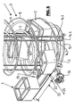
- the drivers 14 are each mounted on a machine axis MA concentric and radially spaced and below the container inlet 4 and below the local trajectory of the container 2 arranged support ring 15, which also the central support structure 12 also at a radial distance encloses.
- the drivers 14 are each attached to a wheel 16 which is rotatably mounted on the shaft 13 about the machine axis MA.
- the two driver sections 14.1 and 14.3 form contact surfaces for the transport section 3 by pushing with the drivers 14 further moved container 2. Only immediately before reaching the container outlet 5 is only the driver portion 14.1 against the respective container.
- the drivers 14 are attached to the support ring 15 and the wheel 16 such that the plane defined by the Mit Spotifyabitesen 14.2 and 14.3 is parallel to that edge region against which the respective driver 14 abuts the trailing in the transport direction A narrow side of a container 2.
- support rings serve at least three provided on the machine frame and the machine axis MA preferably at even angular intervals offset bearing elements 17 which in the illustrated embodiment, one to a horizontal or substantially horizontal, radially Machine axis MA freely rotatable roller 18 for axial support of the support ring 15 and a about an axis parallel to the machine axis MA freely rotatable roller 19 for radial support of the support ring 15 on the ring inside or outside.
- the lower support ring 15 and the upper wheel 16 are synchronously driven about the machine axis MA in the transport direction A, so that with the support ring 15 and the wheel 16 and the driver 14 in the between the sliding guides 6 and 7 and the guide rails 8 and 9 formed free space for carrying the container 2 on the transport path 3 move.
- This machine drive can be realized in many different ways, for example, by independent but synchronized electric motor drives for the wheel 16 and the support ring 15, as indicated in the figures with the two drives 20 and 21, or by a single drive, such as electric motor Drive, with which both the support ring 15 and the wheel 16 are drivingly connected.
- the direct drive of the support ring 15 is characterized in that it is provided with a toothing, in which engages a pinion of the drive or drive train. If the toothing on that annular surface of the support ring 15 is provided on which the radial guidance is carried out, the rollers 19 are designed as a gear, then at least one of these gears is the support ring 15 driving pinion.
- the container inlet 4, via which the containers 2 are also fed with their narrower peripheral sides perpendicular or transversely to the transport direction A of the transport path 3 approximately tangentially to the circulation path of the driver 14, consists essentially of two perpendicular to the transport direction A spaced apart and synchronously driven conveyor belts 22nd and 23, each having a closed loop forming and driven by an electric motor drive 24 endlessly driven transport element, for example in the form of a hinge strap chain.
- the one conveyor belt 22 Due to the tangential arrangement or orientation of the container inlet 4 and the conveyor belts 22 and 23 with respect to the orbit of the driver 14, the one conveyor belt 22 has a greater length than the other conveyor belt 23 , The insertion of the container 2 from the container inlet 4 in the transport path 3 is carried out by the conveyor belts 22 and 23.
- the design and arrangement of the conveyor belts 22 and 23 ensures that each container 2 in the transfer of container inlet 4 to the transport section 3 at any time is sufficiently supported on the conveyor belts 22 and 23 or on the sliding guides 6 and 7 at its container bottom, first at the container bottom on the two conveyor belts 22 and 23, then at the first insertion into the transport path 3 with the container bottom at least in the region of Transport direction A lagging side still on the two conveyor belts 22 and 23 and on the leading in the transport direction A side with the container bottom already on the outer slide 6 and then subsequently with the container bottom on both sliding guides 6 and 7
- the container inlet 4 and the local conveyor belts 22 and 23 and / or not shown, provided on the container inlet 4 retaining elements for the container 2 are controlled such that the introduction of each container 2 is completed in the transport section 3, before a driver 14 the transition achieved between the container inlet and the transport path 3, so that the moving into the transport section 3 container 2 each reliable from the Drivers 14 entrained and moved along the transport path 3.
- the two sliding guides 6 and 7 each terminate in a slide guide 28 for the container bottoms formed by guide plates 26 and 27 in the illustrated embodiment.
- On the slide 28 further two conveyor belts 30 and 31 are provided with drive 32 through which the container 2 from the container outlet 5 to the outer conveyor, not shown, are further promoted.
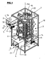
- the spiral conveyor 1 serves as a conveyor or transport device, which allow it with a small size and thus in particular in confined spatial conditions to promote container 2 from a lower level to a higher level.
- the spiral conveyor 1 is preferably part of a device for treating the containers 2, for example a component of a container cleaning system and / or container washing installation, in which the containers 2 are moved, at least on the transport route 3, through different treatment zones, e.g. are formed by spray nozzles for a container inside andindustrialabspritzung.
- different treatment zones e.g. are formed by spray nozzles for a container inside andindustrialabspritzung.
- the container inlet and the container outlet are preferably formed with a tunnel-like housing element, as indicated in the figures with 33 and 34.
- the transport path 3 having the interior of the device is then provided below the transport path with a trained as a collecting tray bottom 35.
- the machine frame below the wall 35 then 10 different functional elements are provided in the machine frame, for example, at least one container for the cleaning and washing liquid, in particular at least one container for in the sump (bottom 35) collected and recycled cleaning and washing liquid, at least one pump, etc .. housed.
- at least one container for the cleaning and washing liquid in particular at least one container for in the sump (bottom 35) collected and recycled cleaning and washing liquid, at least one pump, etc .. housed.
- the spiral conveyor 1 is for example part of a dryer, i.
- 3 outlets or nozzles for blowing off the container 2 are provided with an air flow within the enclosure also closed along the transport path 3 of the device for drying the previously cleaned in another device.
- Below the wall 35 are then, for example, aggregates for generating the blowing air.
- the described design of the spiral conveyor 1 and in particular the use of the support ring 15 has, especially when training this conveyor as a dryer for drying the container 2 by blowing quite significant advantages. Due to the described design is a problem-free arrangement of a relatively large cross section and, for example, slot-shaped nozzle openings having feeds for the blowing air within the space enclosed by the helical transport path 3 space possible, as shown in the FIG. 3 with broken lines at 36 is indicated.
- the feeders are then connected by the support ring 15 with a device, not shown and arranged below the bottom 35 for generating the blowing air.
- the slot-shaped nozzles produce a blast air flow which is directed radially outward with respect to the machine axis MA and which also causes the containers 2 to be effectively dried, assisted by the centrifugal forces acting on liquid residues on the containers 2.
- the bearing takes place lower Mit whichtragiatas formed by the support ring 15 at a radial distance from the machine axis MA, the (distance) is equal to or substantially equal to half the diameter of the support ring 15.
- the radial distance is preferably at least 50% of half the diameter of the support ring 15.
- the container inlet 4 and the container outlet 5 are on a common side of the machine frame 10 provided, according to the tangential course of the conveying direction A on the container inlet and the container outlet 5 with respect to the course of the conveying direction within the transport path 3 on different vertical sides of the machine frame 10.
- the containers 2 are moved along the transport path 3 from bottom to top. In principle, it is also possible to move the containers 2 in the reverse direction from the upper end to the lower end of the transport path, in particular with a correspondingly small gradient of the coiled transport path 3.
Landscapes
- Structure Of Belt Conveyors (AREA)
- Specific Conveyance Elements (AREA)
Claims (13)
- Transporteur hélicoïdal pour des conteneurs (2) sous la forme de caissons de transport avec au moins un trajet de transport (3) entourant à la manière d'une hélice un axe vertical de machine (MA) et s'étendant entre une entrée (4) de conteneurs et une sortie (5) de conteneurs, qui est défini par des éléments de guidage et/ou de glissement des conteneurs (6, 7, 8, 9) externes en rapport à l'axe de la machine (MA), ainsi qu'internes en rapport à l'axe de la machine (MA), lesquels forment un plan de transport ou de glissement sur lequel sont posés les conteneurs (2), ainsi que des balustrades de guidage pour les conteneurs (2), ainsi qu'avec au moins un élément d'entraînement (14) qui s'étend sur toute la longueur de l'hélice formée par le trajet de transport (3) et qui traverse le trajet de transport (3) entre les éléments de guidage et/ou de glissement des conteneurs (6, 7, 8, 9) internes et externes, l'au moins un élément d'entraînement (14) étant maintenu sur au moins deux éléments porteurs (15, 16) d'élément d'entraînement susceptibles d'être entraînés en périphérie autour de l'axe de la machine (MA) pour un déplacement sur une orbite entourant l'axe de la machine (MA), les balustrades de guidage (8, 9) s'étendant au-dessus du plan de transport ou plan de coulissement et en rapport à l'axe de la machine (MA) et en rapport à l'au moins un élément d'entraînement (14) formant une balustrade de guidage (8) latérale externe en direction radiale et une balustrade de guidage (9) latérale interne en direction radiale,
caractérisé en ce qu'un des éléments porteurs d'élément d'entraînement est un anneau porteur (15) rotatif, avec un palier à distance radial de l'axe de la machine (MA) et en ce que l'au moins un élément d'entraînement (14) est fixé par une extrémité sur l'anneau porteur (15) inférieure et par une extrémité sur une roue supérieure, (16) entraînée en périphérie par un entraînement (20) autour de l'axe de la machine (MA) et formant le deuxième élément porteur d'élément d'entraînement. - Transporteur hélicoïdal selon la revendication 1, caractérisé en ce que La distance radiale du logement est égale ou sensiblement égale au demi-diamètre de l'anneau porteur, mais au moins supérieur à 50 % du demi-diamètre d'anneau porteur (15),
et/ou
en ce que l'anneau porteur (15) est une partie d'une couronne de pivotement ou est raccordé à celle-ci,
et/ou
en ce que l'anneau porteur (15) est logé sur plusieurs dispositifs de palier (17) déportés autour de l'axe de la machine (MA) et espacés de celui-ci en direction radiale, qui assurent un appui axial et radial d'anneau porteur (15). - Transporteur hélicoïdal selon la revendication 1 ou la revendication 2, caractérisé en ce que l'entrée (4) de conteneurs et/ou la sortie (5) de conteneurs sont formées pour une direction de transport (A) des conteneurs (2), de manière tangentielle ou sensiblement tangentielle à la direction de transport (A) du trajet de transport (3).
- Transporteur hélicoïdal selon l'une quelconque des revendications précédentes, caractérisé en ce que l'entrée (4) de conteneurs comporte au moins un élément de transport (22), de préférence sous la forme d'une bande transporteuse (22), lequel est orienté de manière tangentielle ou sensiblement tangentielle en rapport aux éléments de guidage et/ou de glissement des conteneurs (6, 8) externes.
- Transporteur hélicoïdal selon l'une quelconque des revendications précédentes, caractérisé en ce que l'entrée (4) de conteneurs comporte au moins un élément de transport, de préférence une bande transporteuse (23), lequel est orienté de manière tangentielle ou sensiblement tangentielle en rapport aux éléments de guidage et/ou de glissement des conteneurs (7, 9) internes.
- Transporteur hélicoïdal selon la revendication 4 ou la revendication 5, caractérisé en ce que les éléments de transport (22, 23) se terminent chacun sur les éléments de guidage et de glissement des conteneurs (6, 8) externes.
- Transporteur hélicoïdal selon l'une quelconque des revendications précédentes, caractérisé en ce que la sortie (5) de conteneurs forme au moins un plan de glissement ou de transport (28, 30, 31) pour les conteneurs (2), dans le plan de transport ou de glissement (28) étant prévue par exemple au moins une échancrure (29) pour l'au moins un élément d'entraînement (14) recoupant ledit plan de transport.
- Transporteur hélicoïdal selon l'une quelconque des revendications précédentes, caractérisé en ce que l'entrée (4) de conteneurs et la sortie (5) de conteneurs sont prévus sur un côté commun d'un bâti de machine (10) du transporteur hélicoïdal et/ou sur différents niveaux de hauteur, à savoir de préférence la sortie (5) de conteneurs au-dessus de l'entrée (4) de conteneurs.
- Transporteur hélicoïdal selon l'une quelconque des revendications précédentes, caractérisé par une commande commune ou encore par des commandes séparées synchronisées pour les éléments porteurs (15, 16) d'élément d'entraînement.
- Transporteur hélicoïdal selon l'une quelconque des revendications précédentes, caractérisé par sa configuration comme dispositif destiné à traiter, notamment à nettoyer et/ou à sécher les conteneurs (2).
- Transporteur hélicoïdal selon la revendication 10, caractérisé en ce qu'à l'intérieur d'un espace entourant le trajet de transport (3) sont prévus des éléments fonctionnels (36) destinés à traiter, notamment à nettoyer et/ou à sécher les conteneurs (2), ainsi que des conduits ou canaux d'alimentation, notamment pour lesdits éléments fonctionnels (36).
- Transporteur hélicoïdal selon l'une quelconque des revendications précédentes, caractérisé en ce qu'en-dessous de l'élément porteur d'élément d'entraînement inférieur, de préférence en-dessous d'anneau porteur (15) est prévue une paroi (35) conçue de préférence en tant que cuve.
- Transporteur hélicoïdal selon l'une quelconque des revendications précédentes, caractérisé en ce qu'au moins un élément porteur inférieur d'élément d'entraînement est conçu en tant qu'anneau porteur (15).
Priority Applications (2)
| Application Number | Priority Date | Filing Date | Title |
|---|---|---|---|
| SI201030106A SI2279803T2 (sl) | 2009-07-29 | 2010-07-02 | Spiralni transporter |
| SI201030106T SI2279803T1 (sl) | 2009-07-29 | 2010-07-02 | Spiralni transporter |
Applications Claiming Priority (1)
| Application Number | Priority Date | Filing Date | Title |
|---|---|---|---|
| DE102009035273.2A DE102009035273B4 (de) | 2009-07-29 | 2009-07-29 | Wendelförderer |
Publications (3)
| Publication Number | Publication Date |
|---|---|
| EP2279803A1 EP2279803A1 (fr) | 2011-02-02 |
| EP2279803B1 EP2279803B1 (fr) | 2012-09-19 |
| EP2279803B2 true EP2279803B2 (fr) | 2016-03-02 |
Family
ID=43034644
Family Applications (1)
| Application Number | Title | Priority Date | Filing Date |
|---|---|---|---|
| EP10006871.7A Active EP2279803B2 (fr) | 2009-07-29 | 2010-07-02 | Transporteur hélicoïdal |
Country Status (6)
| Country | Link |
|---|---|
| US (1) | US8276746B2 (fr) |
| EP (1) | EP2279803B2 (fr) |
| CN (1) | CN101987324A (fr) |
| DE (1) | DE102009035273B4 (fr) |
| DK (1) | DK2279803T4 (fr) |
| SI (2) | SI2279803T1 (fr) |
Families Citing this family (16)
| Publication number | Priority date | Publication date | Assignee | Title |
|---|---|---|---|---|
| CN102448856B (zh) * | 2009-05-27 | 2014-07-09 | 布兰塔根国际公司 | 塔式结构及其传送系统及传送容器的方法 |
| DE202013101987U1 (de) | 2013-05-07 | 2013-08-09 | Ulrich Klotzki | Wendelförderer |
| WO2015073191A1 (fr) | 2013-11-12 | 2015-05-21 | Transnorm System, Inc. | Latte pour un convoyeur |
| CN105668154B (zh) * | 2014-11-18 | 2018-07-03 | 广州达意隆包装机械股份有限公司 | 螺旋输送装置 |
| NL2014054B1 (nl) * | 2014-12-24 | 2016-10-12 | Ambaflex Int B V | Transporteur. |
| US10201122B2 (en) | 2015-01-23 | 2019-02-12 | Kevin W. Higgins | Large-scale helical farming apparatus |
| CN104970079B (zh) * | 2015-06-23 | 2017-02-22 | 杜登锋 | 离心回转输送器及带有该离心回转输送器的鱼类宰杀机 |
| CN106429247B (zh) * | 2016-09-21 | 2019-04-16 | 江汉大学 | 一种新型货物装载装置 |
| CN107413795A (zh) * | 2017-04-26 | 2017-12-01 | 重庆乐嚼食品有限公司 | 罐头盒清洗风干装置 |
| CN107416282B (zh) * | 2017-04-26 | 2019-03-15 | 重庆乐嚼食品有限公司 | 罐头盒清洗传送机构 |
| CN107976024B (zh) * | 2017-12-26 | 2024-05-03 | 南京厨优堂科技有限公司 | 一种薄壁衬套自动烘干设备 |
| ES2966601T3 (es) * | 2019-03-29 | 2024-04-23 | Specialty Conveyor Bv | Un transportador de acumulación |
| CN112896886A (zh) * | 2021-01-20 | 2021-06-04 | 钱军 | 一种多功能物流仓储转运装置 |
| CN113199856B (zh) * | 2021-04-20 | 2023-12-12 | 内蒙古和瑞包装有限公司 | 一种包装纸箱印刷加工用烘干装置 |
| CN116119247B (zh) * | 2023-04-19 | 2023-06-23 | 泉州绿光达电子科技有限公司 | 一种太阳灯加工用运载装置 |
| US12102081B1 (en) * | 2024-03-22 | 2024-10-01 | Prince Mohammad Bin Fahd University | Vertical farming spraying system |
Citations (1)
| Publication number | Priority date | Publication date | Assignee | Title |
|---|---|---|---|---|
| US3032798A (en) † | 1960-02-09 | 1962-05-08 | Lodge & Shipley Co | Case cleaning machine |
Family Cites Families (12)
| Publication number | Priority date | Publication date | Assignee | Title |
|---|---|---|---|---|
| US1046062A (en) * | 1906-12-11 | 1912-12-03 | Charles E Felt | Bottle-washing machine. |
| US1892206A (en) * | 1932-01-14 | 1932-12-27 | Alvey Mfg Company | Conveyer |
| US2628708A (en) * | 1951-01-25 | 1953-02-17 | Ballentine & Sons P | Article raising or lowering conveyer |
| GB1024113A (en) * | 1963-05-21 | 1966-03-30 | Hydromation Engineering Compan | Improvements in and relating to storage and transfer devices |
| US3295666A (en) * | 1965-10-21 | 1967-01-03 | F Jos Lamb Company Inc | Helical storage unit |
| DE3315413A1 (de) * | 1983-04-28 | 1984-10-31 | Robert 5470 Andernach Mürtz | Vorrichtung zum reinigen von behaeltern |
| JPS59195118U (ja) * | 1983-06-10 | 1984-12-25 | 麒麟麦酒株式会社 | 容器昇降装置 |
| US5291987A (en) * | 1993-03-25 | 1994-03-08 | Millard Manufacturing Corp. | Conveyor for raising and lowering articles |
| US5297668A (en) * | 1993-06-29 | 1994-03-29 | Millard Mfg. Corp. | Conveyor for raising and lowering containers including means for manually removing containers therefrom |
| DE10116854B4 (de) | 2001-04-04 | 2005-07-07 | Ulrich Klotzki | Waschanlage zum Reinigen von Behältnissen für den Transport und/oder die Aufbewahrung z. B. von Flaschen wie Getränkeflaschen |
| EP1952900A1 (fr) * | 2007-01-30 | 2008-08-06 | Ulrich Klotzki | Dispositif de nettoyage de récipients |
| DE102007005994B4 (de) * | 2007-02-07 | 2010-08-26 | Lang Technik Gmbh | Puffereinrichtung |
-
2009
- 2009-07-29 DE DE102009035273.2A patent/DE102009035273B4/de active Active
-
2010
- 2010-07-02 DK DK10006871.7T patent/DK2279803T4/en active
- 2010-07-02 SI SI201030106T patent/SI2279803T1/sl unknown
- 2010-07-02 EP EP10006871.7A patent/EP2279803B2/fr active Active
- 2010-07-02 SI SI201030106A patent/SI2279803T2/sl unknown
- 2010-07-28 CN CN2010102437503A patent/CN101987324A/zh active Pending
- 2010-07-28 US US12/805,375 patent/US8276746B2/en active Active
Patent Citations (1)
| Publication number | Priority date | Publication date | Assignee | Title |
|---|---|---|---|---|
| US3032798A (en) † | 1960-02-09 | 1962-05-08 | Lodge & Shipley Co | Case cleaning machine |
Also Published As
| Publication number | Publication date |
|---|---|
| CN101987324A (zh) | 2011-03-23 |
| DE102009035273B4 (de) | 2016-07-07 |
| US8276746B2 (en) | 2012-10-02 |
| EP2279803B1 (fr) | 2012-09-19 |
| DK2279803T4 (en) | 2016-04-25 |
| SI2279803T1 (sl) | 2013-01-31 |
| DE102009035273A1 (de) | 2011-02-03 |
| SI2279803T2 (sl) | 2016-07-29 |
| US20110024267A1 (en) | 2011-02-03 |
| EP2279803A1 (fr) | 2011-02-02 |
| DK2279803T3 (da) | 2013-01-02 |
Similar Documents
| Publication | Publication Date | Title |
|---|---|---|
| EP2279803B2 (fr) | Transporteur hélicoïdal | |
| EP0485937B1 (fr) | Dispositif de groupement | |
| DE3301525C2 (fr) | ||
| DE60118772T2 (de) | Zufuhrsystem für vorformen insbesondere geeignet für eine behälter blasmaschine | |
| DE3873292T2 (de) | Automatische anlage zum aufrichten und in einer reihe aufstellen von behaeltern. | |
| WO2006087109A1 (fr) | Système de table avant | |
| EP2583919B1 (fr) | Dispositif de transport d'objets | |
| DE3916671C2 (de) | Verfahren und Vorrichtung zum aufeinanderfolgenden Fördern von flachen Süßigkeiten | |
| DE102010051283B4 (de) | Wendelförderer | |
| DE3315413A1 (de) | Vorrichtung zum reinigen von behaeltern | |
| DE4400871C2 (de) | Vorrichtung zum Waschen bzw. Reinigen von Flaschenkästen | |
| DE2855982A1 (de) | Stueckgut-transportvorrichtung | |
| EP1530542B1 (fr) | Dispositif de sterilisation pour bouchons de contenants de boisson | |
| CH627995A5 (de) | Vorrichtung zum ausrichten von flaschen. | |
| DE102004049330A1 (de) | Vortisch für Behälterbehandlungsmaschinen | |
| EP1952900A1 (fr) | Dispositif de nettoyage de récipients | |
| DE102008049296A1 (de) | Vorrichtung zum Abblasen oder Trocknen von Kästen oder dergleichen Behältern | |
| EP2647443B1 (fr) | Dispositif de nettoyage de récipients | |
| DE202013101987U1 (de) | Wendelförderer | |
| DE3431447C2 (fr) | ||
| DE3148796C2 (fr) | ||
| DE3611494C2 (fr) | ||
| DE69710153T2 (de) | Vorrichtung zur Behandlung der Oberfläche von Zwiebel- und Knollengewächsen | |
| DE1757702A1 (de) | Verfahren und Vorrichtung zum Reinigen und Wenden von kastenfoermigen Behaeltern | |
| EP1166902B1 (fr) | Dispositif pour nettoyer des caisses |
Legal Events
| Date | Code | Title | Description |
|---|---|---|---|
| PUAI | Public reference made under article 153(3) epc to a published international application that has entered the european phase |
Free format text: ORIGINAL CODE: 0009012 |
|
| AK | Designated contracting states |
Kind code of ref document: A1 Designated state(s): AL AT BE BG CH CY CZ DE DK EE ES FI FR GB GR HR HU IE IS IT LI LT LU LV MC MK MT NL NO PL PT RO SE SI SK SM TR |
|
| AX | Request for extension of the european patent |
Extension state: BA ME RS |
|
| 17P | Request for examination filed |
Effective date: 20110524 |
|
| GRAP | Despatch of communication of intention to grant a patent |
Free format text: ORIGINAL CODE: EPIDOSNIGR1 |
|
| GRAS | Grant fee paid |
Free format text: ORIGINAL CODE: EPIDOSNIGR3 |
|
| GRAA | (expected) grant |
Free format text: ORIGINAL CODE: 0009210 |
|
| AK | Designated contracting states |
Kind code of ref document: B1 Designated state(s): AL AT BE BG CH CY CZ DE DK EE ES FI FR GB GR HR HU IE IS IT LI LT LU LV MC MK MT NL NO PL PT RO SE SI SK SM TR |
|
| REG | Reference to a national code |
Ref country code: GB Ref legal event code: FG4D Free format text: NOT ENGLISH |
|
| REG | Reference to a national code |
Ref country code: CH Ref legal event code: EP |
|
| REG | Reference to a national code |
Ref country code: IE Ref legal event code: FG4D Free format text: LANGUAGE OF EP DOCUMENT: GERMAN |
|
| REG | Reference to a national code |
Ref country code: AT Ref legal event code: REF Ref document number: 575711 Country of ref document: AT Kind code of ref document: T Effective date: 20121015 |
|
| REG | Reference to a national code |
Ref country code: CH Ref legal event code: NV Representative=s name: LUCHS & PARTNER AG PATENTANWAELTE |
|
| REG | Reference to a national code |
Ref country code: DE Ref legal event code: R096 Ref document number: 502010001267 Country of ref document: DE Effective date: 20121115 |
|
| REG | Reference to a national code |
Ref country code: NL Ref legal event code: T3 |
|
| REG | Reference to a national code |
Ref country code: DK Ref legal event code: T3 |
|
| PG25 | Lapsed in a contracting state [announced via postgrant information from national office to epo] |
Ref country code: FI Free format text: LAPSE BECAUSE OF FAILURE TO SUBMIT A TRANSLATION OF THE DESCRIPTION OR TO PAY THE FEE WITHIN THE PRESCRIBED TIME-LIMIT Effective date: 20120919 Ref country code: NO Free format text: LAPSE BECAUSE OF FAILURE TO SUBMIT A TRANSLATION OF THE DESCRIPTION OR TO PAY THE FEE WITHIN THE PRESCRIBED TIME-LIMIT Effective date: 20121219 Ref country code: HR Free format text: LAPSE BECAUSE OF FAILURE TO SUBMIT A TRANSLATION OF THE DESCRIPTION OR TO PAY THE FEE WITHIN THE PRESCRIBED TIME-LIMIT Effective date: 20120919 Ref country code: LT Free format text: LAPSE BECAUSE OF FAILURE TO SUBMIT A TRANSLATION OF THE DESCRIPTION OR TO PAY THE FEE WITHIN THE PRESCRIBED TIME-LIMIT Effective date: 20120919 |
|
| REG | Reference to a national code |
Ref country code: LT Ref legal event code: MG4D Effective date: 20120919 |
|
| PG25 | Lapsed in a contracting state [announced via postgrant information from national office to epo] |
Ref country code: GR Free format text: LAPSE BECAUSE OF FAILURE TO SUBMIT A TRANSLATION OF THE DESCRIPTION OR TO PAY THE FEE WITHIN THE PRESCRIBED TIME-LIMIT Effective date: 20121220 Ref country code: LV Free format text: LAPSE BECAUSE OF FAILURE TO SUBMIT A TRANSLATION OF THE DESCRIPTION OR TO PAY THE FEE WITHIN THE PRESCRIBED TIME-LIMIT Effective date: 20120919 Ref country code: SE Free format text: LAPSE BECAUSE OF FAILURE TO SUBMIT A TRANSLATION OF THE DESCRIPTION OR TO PAY THE FEE WITHIN THE PRESCRIBED TIME-LIMIT Effective date: 20120919 |
|
| PG25 | Lapsed in a contracting state [announced via postgrant information from national office to epo] |
Ref country code: ES Free format text: LAPSE BECAUSE OF FAILURE TO SUBMIT A TRANSLATION OF THE DESCRIPTION OR TO PAY THE FEE WITHIN THE PRESCRIBED TIME-LIMIT Effective date: 20121230 Ref country code: IS Free format text: LAPSE BECAUSE OF FAILURE TO SUBMIT A TRANSLATION OF THE DESCRIPTION OR TO PAY THE FEE WITHIN THE PRESCRIBED TIME-LIMIT Effective date: 20130119 Ref country code: RO Free format text: LAPSE BECAUSE OF FAILURE TO SUBMIT A TRANSLATION OF THE DESCRIPTION OR TO PAY THE FEE WITHIN THE PRESCRIBED TIME-LIMIT Effective date: 20120919 Ref country code: EE Free format text: LAPSE BECAUSE OF FAILURE TO SUBMIT A TRANSLATION OF THE DESCRIPTION OR TO PAY THE FEE WITHIN THE PRESCRIBED TIME-LIMIT Effective date: 20120919 |
|
| PG25 | Lapsed in a contracting state [announced via postgrant information from national office to epo] |
Ref country code: PL Free format text: LAPSE BECAUSE OF FAILURE TO SUBMIT A TRANSLATION OF THE DESCRIPTION OR TO PAY THE FEE WITHIN THE PRESCRIBED TIME-LIMIT Effective date: 20120919 Ref country code: PT Free format text: LAPSE BECAUSE OF FAILURE TO SUBMIT A TRANSLATION OF THE DESCRIPTION OR TO PAY THE FEE WITHIN THE PRESCRIBED TIME-LIMIT Effective date: 20130121 Ref country code: SK Free format text: LAPSE BECAUSE OF FAILURE TO SUBMIT A TRANSLATION OF THE DESCRIPTION OR TO PAY THE FEE WITHIN THE PRESCRIBED TIME-LIMIT Effective date: 20120919 |
|
| PLBI | Opposition filed |
Free format text: ORIGINAL CODE: 0009260 |
|
| PLAX | Notice of opposition and request to file observation + time limit sent |
Free format text: ORIGINAL CODE: EPIDOSNOBS2 |
|
| 26 | Opposition filed |
Opponent name: ALPE BETRIEBSEINRICHTUNG, HYGIENE- UND UMWELTTECHN Effective date: 20130618 |
|
| PG25 | Lapsed in a contracting state [announced via postgrant information from national office to epo] |
Ref country code: BG Free format text: LAPSE BECAUSE OF FAILURE TO SUBMIT A TRANSLATION OF THE DESCRIPTION OR TO PAY THE FEE WITHIN THE PRESCRIBED TIME-LIMIT Effective date: 20121219 |
|
| REG | Reference to a national code |
Ref country code: DE Ref legal event code: R026 Ref document number: 502010001267 Country of ref document: DE Effective date: 20130618 |
|
| PLBB | Reply of patent proprietor to notice(s) of opposition received |
Free format text: ORIGINAL CODE: EPIDOSNOBS3 |
|
| PG25 | Lapsed in a contracting state [announced via postgrant information from national office to epo] |
Ref country code: CY Free format text: LAPSE BECAUSE OF FAILURE TO SUBMIT A TRANSLATION OF THE DESCRIPTION OR TO PAY THE FEE WITHIN THE PRESCRIBED TIME-LIMIT Effective date: 20120919 |
|
| PG25 | Lapsed in a contracting state [announced via postgrant information from national office to epo] |
Ref country code: MC Free format text: LAPSE BECAUSE OF FAILURE TO SUBMIT A TRANSLATION OF THE DESCRIPTION OR TO PAY THE FEE WITHIN THE PRESCRIBED TIME-LIMIT Effective date: 20120919 |
|
| REG | Reference to a national code |
Ref country code: IE Ref legal event code: MM4A |
|
| PLAY | Examination report in opposition despatched + time limit |
Free format text: ORIGINAL CODE: EPIDOSNORE2 |
|
| PG25 | Lapsed in a contracting state [announced via postgrant information from national office to epo] |
Ref country code: IE Free format text: LAPSE BECAUSE OF NON-PAYMENT OF DUE FEES Effective date: 20130702 |
|
| PLBC | Reply to examination report in opposition received |
Free format text: ORIGINAL CODE: EPIDOSNORE3 |
|
| PG25 | Lapsed in a contracting state [announced via postgrant information from national office to epo] |
Ref country code: SM Free format text: LAPSE BECAUSE OF FAILURE TO SUBMIT A TRANSLATION OF THE DESCRIPTION OR TO PAY THE FEE WITHIN THE PRESCRIBED TIME-LIMIT Effective date: 20120919 |
|
| REG | Reference to a national code |
Ref country code: FR Ref legal event code: PLFP Year of fee payment: 6 |
|
| PG25 | Lapsed in a contracting state [announced via postgrant information from national office to epo] |
Ref country code: MT Free format text: LAPSE BECAUSE OF FAILURE TO SUBMIT A TRANSLATION OF THE DESCRIPTION OR TO PAY THE FEE WITHIN THE PRESCRIBED TIME-LIMIT Effective date: 20120919 |
|
| PG25 | Lapsed in a contracting state [announced via postgrant information from national office to epo] |
Ref country code: MK Free format text: LAPSE BECAUSE OF FAILURE TO SUBMIT A TRANSLATION OF THE DESCRIPTION OR TO PAY THE FEE WITHIN THE PRESCRIBED TIME-LIMIT Effective date: 20120919 Ref country code: LU Free format text: LAPSE BECAUSE OF NON-PAYMENT OF DUE FEES Effective date: 20130702 Ref country code: HU Free format text: LAPSE BECAUSE OF FAILURE TO SUBMIT A TRANSLATION OF THE DESCRIPTION OR TO PAY THE FEE WITHIN THE PRESCRIBED TIME-LIMIT; INVALID AB INITIO Effective date: 20100702 |
|
| RIC2 | Information provided on ipc code assigned after grant |
Ipc: B65G 11/06 20060101ALI20150826BHEP Ipc: B65B 55/24 20060101ALN20150826BHEP Ipc: B08B 9/08 20060101AFI20150826BHEP Ipc: B65G 21/18 20060101ALI20150826BHEP |
|
| RAP2 | Party data changed (patent owner data changed or rights of a patent transferred) |
Owner name: KLOTZKI MASCHINENBAU GMBH |
|
| RIN2 | Information on inventor provided after grant (corrected) |
Inventor name: KLOTZKI, ULRICH |
|
| PUAH | Patent maintained in amended form |
Free format text: ORIGINAL CODE: 0009272 |
|
| STAA | Information on the status of an ep patent application or granted ep patent |
Free format text: STATUS: PATENT MAINTAINED AS AMENDED |
|
| 27A | Patent maintained in amended form |
Effective date: 20160302 |
|
| AK | Designated contracting states |
Kind code of ref document: B2 Designated state(s): AL AT BE BG CH CY CZ DE DK EE ES FI FR GB GR HR HU IE IS IT LI LT LU LV MC MK MT NL NO PL PT RO SE SI SK SM TR |
|
| REG | Reference to a national code |
Ref country code: DE Ref legal event code: R102 Ref document number: 502010001267 Country of ref document: DE |
|
| REG | Reference to a national code |
Ref country code: CH Ref legal event code: AELC |
|
| REG | Reference to a national code |
Ref country code: DK Ref legal event code: T4 Effective date: 20160418 |
|
| REG | Reference to a national code |
Ref country code: NL Ref legal event code: FP |
|
| REG | Reference to a national code |
Ref country code: GB Ref legal event code: 732E Free format text: REGISTERED BETWEEN 20160526 AND 20160601 |
|
| REG | Reference to a national code |
Ref country code: FR Ref legal event code: PLFP Year of fee payment: 7 |
|
| REG | Reference to a national code |
Ref country code: SI Ref legal event code: SP73 Owner name: KLOTZKI MASCHINENBAU GMBH; DE Effective date: 20160914 |
|
| REG | Reference to a national code |
Ref country code: FR Ref legal event code: PLFP Year of fee payment: 8 |
|
| REG | Reference to a national code |
Ref country code: FR Ref legal event code: PLFP Year of fee payment: 9 |
|
| PG25 | Lapsed in a contracting state [announced via postgrant information from national office to epo] |
Ref country code: AL Free format text: LAPSE BECAUSE OF FAILURE TO SUBMIT A TRANSLATION OF THE DESCRIPTION OR TO PAY THE FEE WITHIN THE PRESCRIBED TIME-LIMIT Effective date: 20120919 |
|
| P01 | Opt-out of the competence of the unified patent court (upc) registered |
Effective date: 20230509 |
|
| PGFP | Annual fee paid to national office [announced via postgrant information from national office to epo] |
Ref country code: IT Payment date: 20230724 Year of fee payment: 14 Ref country code: GB Payment date: 20230720 Year of fee payment: 14 Ref country code: CH Payment date: 20230802 Year of fee payment: 14 Ref country code: AT Payment date: 20230720 Year of fee payment: 14 |
|
| PGFP | Annual fee paid to national office [announced via postgrant information from national office to epo] |
Ref country code: SI Payment date: 20230623 Year of fee payment: 14 Ref country code: FR Payment date: 20230725 Year of fee payment: 14 Ref country code: DK Payment date: 20230721 Year of fee payment: 14 Ref country code: BE Payment date: 20230719 Year of fee payment: 14 |
|
| PGFP | Annual fee paid to national office [announced via postgrant information from national office to epo] |
Ref country code: CZ Payment date: 20240624 Year of fee payment: 15 |
|
| PGFP | Annual fee paid to national office [announced via postgrant information from national office to epo] |
Ref country code: TR Payment date: 20240624 Year of fee payment: 15 |
|
| PGFP | Annual fee paid to national office [announced via postgrant information from national office to epo] |
Ref country code: NL Payment date: 20240719 Year of fee payment: 15 |
|
| PGFP | Annual fee paid to national office [announced via postgrant information from national office to epo] |
Ref country code: DE Payment date: 20240730 Year of fee payment: 15 |