EP2279111B1 - Unterseeboot mit einem propulsionsantrieb mit einem elektroringmotor - Google Patents
Unterseeboot mit einem propulsionsantrieb mit einem elektroringmotor Download PDFInfo
- Publication number
- EP2279111B1 EP2279111B1 EP09765707.6A EP09765707A EP2279111B1 EP 2279111 B1 EP2279111 B1 EP 2279111B1 EP 09765707 A EP09765707 A EP 09765707A EP 2279111 B1 EP2279111 B1 EP 2279111B1
- Authority
- EP
- European Patent Office
- Prior art keywords
- rotor
- submarine
- motor
- propulsion drive
- electric motor
- Prior art date
- Legal status (The legal status is an assumption and is not a legal conclusion. Google has not performed a legal analysis and makes no representation as to the accuracy of the status listed.)
- Active
Links
Images


Classifications
-
- B—PERFORMING OPERATIONS; TRANSPORTING
- B63—SHIPS OR OTHER WATERBORNE VESSELS; RELATED EQUIPMENT
- B63G—OFFENSIVE OR DEFENSIVE ARRANGEMENTS ON VESSELS; MINE-LAYING; MINE-SWEEPING; SUBMARINES; AIRCRAFT CARRIERS
- B63G8/00—Underwater vessels, e.g. submarines; Equipment specially adapted therefor
- B63G8/08—Propulsion
-
- B—PERFORMING OPERATIONS; TRANSPORTING
- B63—SHIPS OR OTHER WATERBORNE VESSELS; RELATED EQUIPMENT
- B63H—MARINE PROPULSION OR STEERING
- B63H1/00—Propulsive elements directly acting on water
- B63H1/02—Propulsive elements directly acting on water of rotary type
- B63H1/12—Propulsive elements directly acting on water of rotary type with rotation axis substantially in propulsive direction
- B63H1/14—Propellers
- B63H1/16—Propellers having a shrouding ring attached to blades
-
- B—PERFORMING OPERATIONS; TRANSPORTING
- B63—SHIPS OR OTHER WATERBORNE VESSELS; RELATED EQUIPMENT
- B63H—MARINE PROPULSION OR STEERING
- B63H21/00—Use of propulsion power plant or units on vessels
- B63H21/12—Use of propulsion power plant or units on vessels the vessels being motor-driven
- B63H21/17—Use of propulsion power plant or units on vessels the vessels being motor-driven by electric motor
-
- B—PERFORMING OPERATIONS; TRANSPORTING
- B63—SHIPS OR OTHER WATERBORNE VESSELS; RELATED EQUIPMENT
- B63H—MARINE PROPULSION OR STEERING
- B63H23/00—Transmitting power from propulsion power plant to propulsive elements
- B63H23/22—Transmitting power from propulsion power plant to propulsive elements with non-mechanical gearing
- B63H23/24—Transmitting power from propulsion power plant to propulsive elements with non-mechanical gearing electric
-
- H—ELECTRICITY
- H02—GENERATION; CONVERSION OR DISTRIBUTION OF ELECTRIC POWER
- H02K—DYNAMO-ELECTRIC MACHINES
- H02K7/00—Arrangements for handling mechanical energy structurally associated with dynamo-electric machines, e.g. structural association with mechanical driving motors or auxiliary dynamo-electric machines
- H02K7/14—Structural association with mechanical loads, e.g. with hand-held machine tools or fans
-
- B—PERFORMING OPERATIONS; TRANSPORTING
- B63—SHIPS OR OTHER WATERBORNE VESSELS; RELATED EQUIPMENT
- B63H—MARINE PROPULSION OR STEERING
- B63H1/00—Propulsive elements directly acting on water
- B63H1/02—Propulsive elements directly acting on water of rotary type
- B63H1/12—Propulsive elements directly acting on water of rotary type with rotation axis substantially in propulsive direction
- B63H1/14—Propellers
- B63H1/16—Propellers having a shrouding ring attached to blades
- B63H2001/165—Hubless propellers, e.g. peripherally driven shrouds with blades projecting from the shrouds' inside surfaces
-
- B—PERFORMING OPERATIONS; TRANSPORTING
- B63—SHIPS OR OTHER WATERBORNE VESSELS; RELATED EQUIPMENT
- B63H—MARINE PROPULSION OR STEERING
- B63H23/00—Transmitting power from propulsion power plant to propulsive elements
- B63H2023/005—Transmitting power from propulsion power plant to propulsive elements using a drive acting on the periphery of a rotating propulsive element, e.g. on a dented circumferential ring on a propeller, or a propeller acting as rotor of an electric motor
Definitions
- the invention relates to a submarine with a propulsion drive according to claim 1.
- propulsion usually propulsion as a propulsion in the submarine electric motor, which drives a propeller shaft in the longitudinal direction of the boat in extension of the stern outside the boat hull arranged propeller.
- the propeller shaft must penetrate the hull of the submarine in the stern of the submarine. The seal at the point of penetration usually takes place with a shaft seal.
- two propeller shafts in the rear can be guided through the boat hull and propel two side by side in the longitudinal direction of the boat in extension of the stern outside the boat hull arranged propeller (one propeller each on starboard and port side).
- a disadvantage of such a propulsion drive is the relatively large noise emission of the propeller, which facilitates locating the submarine. Also, at great depths, even a small damage to the shaft seal can cause problems for the submarine. Furthermore, a torpedo hit or other damage in the stern of the submarine with rotating propeller shaft can cause the shaft bends and thereby ruptures the tail of the submarine in such a way that it comes to a total loss of the submarine.
- US 7,353,768 Bl discloses an underwater vehicle having a shaft on which a propeller is disposed and a generator / motor having a stator and a rotor coupled to the propeller.
- the underwater vehicle further includes at least one energy store connected to the generator / motor and a control unit by means of which the operating mode of the generator / motor can be adjusted, wherein a charging mode, a drive mode and an idling mode can be set.
- EP 1 739 007 A1 reveals a shaftless propeller.
- the propeller includes a stator having an annular opening and a rotor disposed in the opening of the stator.
- the rotor has an annular rotor body on which a plurality of inwardly directed propeller blades are arranged.
- US 5 078 628 A discloses a shaftless propulsion drive having an annular rotor and an annular stator. On the rotor, a wreath with outwardly directed propeller blades is attached.
- Advantageous embodiments of the submarine are the subject of subclaims 2 to 13.
- a method for operating a particularly advantageous embodiment of a propulsion drive according to the invention is the subject of claim 13.
- Advantageous embodiments of the method are the subject of the subclaims 14 to 16.
- a submarine according to the invention has a propulsion drive arranged outside the boat hull, which is arranged in the longitudinal direction of the submarine in extension of the stern and comprises a housing and a first electric motor.
- the housing forms a nozzle-shaped channel for a flow of water through the channel in a main flow direction from an inlet to an outlet of the channel.
- the first electric motor has a rotor disposed in the channel and rotatably supported in the housing, the rotor being annularly formed with a ring inner side and a ring outer side. According to the wing for propulsion of the submarine are arranged on the inner ring side of the rotor.
- An electric motor with such an annular rotor is often referred to in the literature as "Elektroringmotor” or "RIM drive”.
- the flow space for the water can be made particularly low-resistance and streamlined.
- the electric motor is located outside the boat hull, it does not require space inside the boat hull.
- the propulsion drive even represents a mass that intercepts part of the explosion.
- the propulsion drive additionally comprises at least a second electric motor with a rotor which is also arranged in the channel and rotatably mounted in the housing, wherein the rotor is annularly formed with a ring inside and a Ringau ⁇ enseite, wherein on the ring inside of the rotor wings are arranged, and wherein the rotor of the first electric motor and the rotor of the second electric motor are arranged in the channel in the main flow direction of the water one behind the other.
- the second electric motor is thus designed as a "RIM drive” or "Elektroringmotor".
- a propulsion drive is highly redundant and has a high reliability.
- the maximum drive power can be increased without reducing the efficiency at creeping, whereby the dive time is positively influenced.
- the rotor of the second motor is rotatable independently of the rotor of the first motor to at least partially redirect an outflow of the water, which is different from the main flow direction, caused by the rotor of the first motor, back into the main flow direction.
- the rotors of the electric motors are for this purpose preferably rotatably supported in mutually opposite direction in the housing.
- the rotor of the first electrical motor, which is first arranged in the direction of flow, can thus be controlled in a targeted manner for delivering a torque to the water for propulsion of the submarine.
- the rotor of the second motor of the lossy swirl of the outflow of the rotor of the first motor ie flow components of the water, which deviate from the main flow direction, at least partially redirected in the main flow direction and thus converted into thrust.
- the flow components other than the main flow direction may be radial or circular flow components with respect to the axis of rotation.
- the propulsion drive can also comprise more than two motors with rotors, which are arranged one behind the other in the channel in the main flow direction of the fluid.
- the propulsion drive can be modularly constructed from a plurality of standardized engine units, wherein the number of engine units can be even or even odd.
- the torque outputs of the motors are independently controllable. This makes it possible to adapt the propulsion drive to different fluidic conditions and to set a desired operating mode of the propulsion drive in a targeted manner (for example thrust-optimized, speed-optimized, consumption-optimized, noise-optimized).
- the submarine comprises a control device for controlling the torque outputs of the motors such that the torques output by the motors are in a predetermined relationship to one another.
- torque ratios can be determined, for example, depending on the fluidic conditions, such as e.g. the flow rate of the fluid or other parameters (such as the desired mode of operation) may be stored in the form of characteristics in the controller.
- the controller may control the ratio of torques by controlling the current levels applied to the motors.
- each of the motors for power supply can be electrically connected to a respective power converter.
- a power converter By means of a power converter can be in a simple and reliable way of an electric machine supplied power and thus controlling the torque output by the electric machine.
- the ratio of the delivered torques during operation of the propulsion drive is variable.
- the propulsion drive can thus be optimally adapted to the respectively prevailing in operation fluidic conditions or desired mode.
- the motor (s) is therefore preferably free of a component passing therethrough along the axis of rotation of the rotor (s) thereof.
- the absence of a central shaft also has the advantage that entering the channel foreign body can tilt only bad.
- the annular design of the rotor (the rotors)
- the housing is nozzle-shaped, a particularly high efficiency of the propulsion drive can be achieved.
- a higher thrust than in a free-rotating propeller can be achieved, especially in stall conditions, whereby the maneuverability is increased in narrow waters.
- the submarine has exactly one propulsion drive described above, wherein the rear cone is arranged in the flow direction in front of the inlet of the propulsion drive.
- the tail cone is preferably arranged in a line with the axis of rotation of the rotor or the rotors, i. the end of the tail cone lies exactly on the axis of rotation of the rotor or the rotors of the propulsion drive.
- the tail cone can also be arranged at a distance from this axis of rotation, wherein this distance is then preferably smaller than the distance between the ring inner side of the rotor or the rotors of the rotation axis in order to achieve a uniform flow of the propulsion drive.
- the tail cone may also extend into the propulsion drive or through the propulsion drive.
- the tail cone is then preferably arranged in a line with the axis of rotation of the rotor or the rotors of the propulsion drive.
- the rear cone is formed axially symmetrical, with its axis of symmetry is in line with the axis of rotation of the rotor or the rotors.
- the ends of the blades of the rotor or the rotors of the Propulsionsantriebs can also be rotatably mounted on the rear cone, whereby the stability and thus the power output of the Propulsionsantriebs can be increased.
- the ends of the wings can also be fixed to the tail cone fastened and the tail cone to be rotatably attached to the boat hull.
- the size of the propulsion drive, its arrangement on the tail cone and the shape of the stern of the submarine, in particular the shape of the tail cone, are preferably matched to one another such that a uniform flow of the propulsion drive results, thereby achieving a good efficiency of the propulsion drive and at the same time Cavitation and unwanted noise can be avoided.
- Such system optimization is possible for a person skilled in hydrodynamics without much difficulty.
- a submarine can of course also have exactly two propulsion drives described above, arranged for example alongside one another in the longitudinal direction of the submarine in extension of the stern outside the boat hull (for example one on each starboard and port side).
- a particularly advantageous method for operating a propulsion drive with two electric motors described above is characterized in that an outflow of the water, which deviates from the main flow direction caused by the rotor of the first motor, at least partially from the rotor of the second motor in the main flow direction again is diverted.
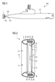
- FIG. 1 shows in a schematic representation of a manned military submarine 100 with a boat hull 101 and a rear 102 of the submarine 100 arranged propulsion drive 1.
- the propulsion drive 1 is the Mannpropulsionsantrieb the submarine.
- the propulsion drive 1 is in the longitudinal direction of the submarine 100 in extension of the stern arranged outside the boat hull 101.
- a submarine as Hauptpropulsionsantrieb also two or more such propulsion drives 1, which are arranged side by side in the longitudinal direction of the submarine 100 in extension of the stern 102 outside the boat hull 101 (eg ever one on starboard and port side)
- the main propulsion drive 1 has a nozzle-shaped housing 2, which forms a tubular channel 3 for a flow of water through the channel 3 in a main flow direction 5 from an inlet 4 to an outlet 6 of the channel 3.
- the propulsion drive 1 comprises an electric motor 10 with a rotor 20 which is arranged in the channel 3 and is rotatably mounted about an axis of rotation 25 in the housing 2, wherein the rotor 20 as a hollow cylinder and thus annularly formed with a ring inner side 21 and a ring outer side 22 is.
- On the inner ring side 21 of the rotor 20 are distributed evenly distributed in the circumferential direction wings 23 for propulsion of the submarine 100.
- Under the outer ring side 22 here is understood the side of the rotor 20, which is defined by the radially outer boundary surface of the rotor 20 and under the ring inner side 21 is the side of the rotor 20 understood, which is defined by the radially inner boundary surface of the rotor 20.
- the main flow direction 5 in this case runs in the direction of the axis of rotation 25 of the rotor 20.
- the rotor 20 is rotatably mounted in the housing 2 on its ring outer side 22 by means of bearings 24 about the axis of rotation 25.
- the However, storage can in principle also be effected by means of bearings on the inside of the ring 21 or on one or both end sides of the annular rotor 20.
- wings 23 rotate with the rotor 20 and are preferably releasably secured in standardized fasteners to the rotor 20 to replace them can.
- the wings 23 may in this case have, for example, an axial, semi-axial or radial shape.
- the rotor 20 thus forms with the attached wings 23 thus an impeller.
- an excitation system 26 is arranged on the ring outer side 22 of the rotor 20. This may be an arrangement of permanent magnets or a winding system, which is arranged distributed in the circumferential direction of the rotor 20 on the outer ring side 22 thereof.
- the motor 10 further comprises a stator 30 with a stator exciter system 31, wherein the stator 30 is arranged in a ring around the rotor 20 so that the stator exciter system 31 and the rotor-side exciter system 26 interact electromagnetically, so that the stator 30 with the rotor 20 electric motor 10 forms.
- a stator 30 with a stator exciter system 31 wherein the stator 30 is arranged in a ring around the rotor 20 so that the stator exciter system 31 and the rotor-side exciter system 26 interact electromagnetically, so that the stator 30 with the rotor 20 electric motor 10 forms.
- Such an electric motor 10 with an annular rotor 20 is often referred to in the literature as "RIM drive” or as "Elektroringmotor”.
- the cables for the power supply to the motor 10 and signal lines for the control and monitoring and monitoring of the motor 10 may for example run in the brackets 103.
- the propulsion drive 1 is designed to be particularly resistant to resistance to the water flowing through the channel 3.
- the motor 10 is free of a component which extends along the axis of rotation 25 of its rotor 20 therethrough.
- the stator 30 is integrated in the housing 2.
- the annular rotor 20 is formed such that the diameter the ring inner side 21 corresponds to the diameter of the channel 3 immediately in front of the rotor 20.
- the annular rotor 20 is for this purpose sunk in the housing 2 or forms with its inner ring side 21, the outer boundary surface of the channel 3 in the region of the rotor 20, said outer boundary surface is aligned with the adjacent, formed by the housing 2 outer boundary surface.
- the ring-shaped rotor 20 itself thus does not constitute a flow resistance for the water beyond the wall friction.
- FIG. 3 shown submarine 100 differs from that in FIG. 1 shown submarine in that it has a propulsion drive 40, which instead of only a single motor 10 now comprises two motors 10, 11.
- each of the motors 10, 11 each comprise a rotor 20 which is formed as a hollow cylinder and thus annular with an inner ring side 21 and a ring outer side 22 and in which 21 wings 23 are arranged on the inner ring side.
- the rotors 20 of the two motors 10, 11 are arranged coaxially one behind the other in the channel 3 in the flow direction of the fluid and mounted with their respective outer ring 22 by means of bearings 24 independently of each other in the same and opposite directions about a common axis of rotation 25 rotatable in the housing 2 ,
- the main flow direction 5 in this case runs in the direction of the axes of rotation 25 of the rotors 20.
- the motors 10, 11 are free of a component which runs along the axis of rotation 25 of their respective rotors 20 therethrough.
- an excitation system 26 is arranged on the ring outer side 22 of the rotors 20, which is, for example, an arrangement of permanent magnets or a winding system which is arranged distributed in the circumferential direction of the rotor 20 on the outside of the ring 22.
- Both motors 10, 11 each comprise a stator 30 with a stator excitation system 31, wherein the stator 30 is arranged in a ring around the rotor 20 such that the stator excitation system 31 and the rotor-side excitation system 26 interact electromagnetically, so that the stator 30 with the rotor 20 forms the electric motor 10 and 11, respectively.
- the rotor 20 of the second motor 11 is rotatable independently of the rotor 20 of the first motor 10 to at least partially redirect an outflow of water caused by the rotor 20 of the first motor 10, which deviates from the main flow direction 5, in the main flow direction 5.
- the rotor 20 of the first electrical motor 10, which is first arranged in the direction of flow, can thus be specifically controlled to deliver a torque to the water for propulsion of the submarine 100.
- the lossy spin of the effluent of the rotor 20 of the first motor 10 i. Flow components of the water, which differ from the main flow direction 5, at least partially redirected in the main flow direction 5 and thus converted into thrust.
- a flow deflection and an at least partial torque compensation is effected.
- a deflection of the deviating from the main flow direction 5 flow components of the water is for example possible that the rotor 20 of the second motor 11 is held stationary or firmly locked or that it is driven by the flowing through the channel 3 water or that he in opposite Direction as the rotor 20 of the first motor 10 is electrically driven, ie that the two rotors 20 kontrarot Schl.
- FIG. 5 in the case of propulsion drive 40 of 3 and FIG. 4 shows, in the case that these two motors 10, 11 comprises, a control device 51 for controlling the Torque outputs of the motors 10, 11 such that the output by the motors 10, 11 torques in a, in particular by the water dynamics, predetermined relationship to each other.
- each of the motors 10, 11 is electrically connected to a respective power converter 52.
- each of the motors 10, 11 is powered via the respective power converter 52 from a power source 53, e.g. a power generator or a fuel cell system, or an energy storage 54, e.g. a battery powered by electricity.
- a power source 53 e.g. a power generator or a fuel cell system
- an energy storage 54 e.g. a battery powered by electricity.
- the control device 51 controls the torques of the motors 10, 11 and thus also the ratio of the torques of the two motors 10, 11 by controlling the currents applied to the motors 10, 11.
- the control device 51 detects these current strengths via signal lines 55 and controls the power converters 52 via control lines 56.
- the ratio of the torques output by the motors 10, 11 is thus variable during operation of the propulsion drive. This allows the ratio to the fluidic conditions and other operating parameters, such as. a desired mode of operation of the propulsion drive 40 (e.g., thrust optimized, speed optimized, fuel efficient, noise optimized), adjusted, and a desired operating point of the propulsion drive 40 adjusted.
- a desired mode of operation of the propulsion drive 40 e.g., thrust optimized, speed optimized, fuel efficient, noise optimized
- characteristic curves or data sets are stored in the control device 51, which describe the dependence of the torque ratio on the fluidic boundary conditions and the operating parameters (for example the desired operating mode).
- a further adaptation of the machine to changed fluidic conditions is possible in that the pitch of the wings 23 is variable.
- the housing 2 of the propulsion drive 1, 40 may also be, e.g. by means of a suitable, possibly gimbal, attachment, horizontally and / or vertically in relation to the boat hull 101 to be movably attached to the boat hull 101.
- the propulsion flow of the propulsion drive 1, 40 can then be directed in different directions, whereby the maneuverability of the submarine can be improved.
- the propulsion drive 40 with two electric motors 10, 11 of 3 - 5 is preferably operated such that caused by the rotor 20 of the first motor 10 outflow of water, which is different from the main flow direction 5, at least partially by the rotor 20 of the second motor 11 is redirected in the main flow direction 5.
- the following three operating modes are available for this purpose:
- the rotor 20 of the first motor 10 is electrically driven.
- the rotor 20 of the second motor 11 is turned on, e.g. by means of a brake, not shown, stationarily held or firmly locked.
- the rotor 20 of the first motor 10 is electrically driven.
- the rotor 20 of the second motor 11 is freely rotatable and is wholly or at least substantially driven by the water flowing through the channel 3.
- the rotor 20 of the second motor 11 can then assume the function of Grimschen a guide wheel, which deviates from the main flow direction 5 and thus lossy flow components of the effluent of the rotor 20 of the first motor 10 at least partially in the main flow direction 5 again.
- the rotor 20 of the second motor 11 can also be held depending on the hydrodynamic design of the second propeller as described above or driven in a counter-rotating manner by the motor 11.
- the rotors 20 of the two motors 10, 11 are electrically driven in the opposite direction, so that they kontrarotieren and cause by the Kontrarotation a desired torque compensation.
- Such a driving regime optimally adjusts the current drawn by the battery or the fuel cell and thus minimizes the power consumption, thereby prolonging the submarine's travel or dive time.
- the hydrodynamic design task is burdened with fewer compromises, since the surface load of the propellers for maximum travel is reduced by the use of 2 propellers.
- the efficiency of the propulsion is improved.
- the boat hull 101 runs out at its seen in the flow direction rear end in a rounded rear portion 104, which is often referred to in the jargon as "tail cone".
- the submarine 100 has exactly one propulsion drive 1 or 40, which is arranged at the stern 102 of the submarine 100 in such a way that this rear cone 104 extends into the inlet 4 of the propulsion drive 1 or 40.
- the size of the propulsion drive, its arrangement on the tail cone 104 and the shape of the stern 102 of the submarine 100, in particular the shape of the tail cone 104, are matched to one another in such a way that a uniform flow of the propulsion drive results, whereby a good efficiency of the propulsion drive is achieved At the same time cavitation and unwanted noise can be avoided.
- the tail cone 104 is arranged in a line to the axis of rotation 25 of the rotor 20 and the rotors 20 of the propulsion drive 1 and 40, respectively.
- the tail cone 104 is in this case formed axially symmetrical, with its axis of symmetry in one Line with the axis of rotation 25 of the rotor 20 and the rotors 20 extends.
- the tail cone 104 may also extend through the propulsion drive 1 or 40, respectively.
- FIG. 6 shows this the propulsion drive 1 of FIG. 2
- the rotor 20 is rotatably mounted not only on the rear cone 104 by means of the bearings 24 in the housing 2, but additionally also on the ends of the wings 23 by means of bearings 105.
- the stability and thus the power output of the propulsion drive 1 can be increased.
- FIG. 7 shows a corresponding embodiment for the case of the propulsion drive 40 of FIG. 4 .
Description
- Die Erfindung betrifft ein Unterseeboot mit einem Propulsionsantrieb gemäß Patentanspruch 1.
- Aktuelle bemannte militärische Unterseeboote (U-Boote) weisen für den Vortrieb üblicherweise als Propulsionsantrieb einen im Unterseeboot angeordneten Elektromotor auf, der über eine Propellerwelle einen in Längsrichtung des Bootes in Verlängerung des Hecks außerhalb der Bootshülle angeordneten Propeller antreibt. Die Propellerwelle muss hierzu im Heck des Unterseebootes die Hülle des Unterseebootes durchdringen. Die Abdichtung an der Durchdringungsstelle erfolgt dabei üblicherweise mit einer Wellendichtung. Bei manchen Typen von Unterseebooten können auch zwei Propellerwellen im Heck durch die Bootshülle geführt sein und zwei nebeneinander in Längsrichtung des Bootes in Verlängerung des Hecks außerhalb der Bootshülle angeordnete Propeller antreiben (je einen Propeller auf Steuerbord- und Backbordseite).
- Nachteilig bei einem derartigen Propulsionsantrieb ist die relativ große Geräuschabstrahlung des Propellers, die eine Ortbarkeit des Unterseebootes erleichtert. Außerdem kann in großen Tiefen bereits eine kleine Beschädigung an der Wellendichtung zu Problemen für das Unterseeboot führen. Weiterhin kann ein Torpedotreffer oder eine andere Beschädigung im Heck des Unterseebootes bei drehender Propellerwelle dazu führen, dass sich die Welle verbiegt und dadurch das Heck des Unterseebootes in solcher Weise aufreißt, dass es zu einem Totalverlust des Unterseebootes kommt.
-
US 7 353 768 Bl offenbart ein Unterwasserfahrzeug mit einer Welle, an der ein Propeller angeordnet ist, und einen Generator/Motor, der einen Stator und einen an den Propeller gekoppelten Rotor aufweist. Das Unterwasserfahrzeug umfasst ferner wenigstens einen mit dem Generator/Motor verbundenen Energiespeicher und eine Steuereinheit, mittels derer der Betriebsmodus des Generators/Motors eingestellt werden kann, wobei ein Auflademodus, ein Antriebsmodus und ein Leerlaufmodus eingestellt werden können. -
EP 1 739 007 Al offenbart einen wellenlosen Propeller. Der Propeller umfasst einen Stator mit einer ringförmigen Öffnung und einen Rotor, der in der Öffnung des Stators angeordnet ist. Der Rotor weist einen ringförmigen Rotorkörper auf, an dem mehrere nach innen gerichtete Propellerblätter angeordnet sind. -
US 5 078 628 A offenbart einen wellenlosen Propulsionsantrieb mit einem ringförmigen Rotor und einem ringförmigen Stator. An dem Rotor ist ein Kranz mit nach außen gerichteten Propellerblättern angebracht. - Es ist deshalb Aufgabe vorliegender Erfindung ein Unterseeboot mit einem Propulsionsantrieb anzugeben, mit dem die vorgenannten Probleme zumindest teilweise vermieden werden können.
- Die Lösung dieser Aufgabe gelingt durch ein Unterseeboot mit einem Propulsionsantrieb gemäß Patentanspruch 1. Vorteilhafte Ausgestaltungen des Unterseebootes sind Gegenstand der Unteransprüche 2 bis 13. Ein Verfahren zum Betrieb einer besonders vorteilhaften Ausgestaltung eines erfindungsgemäßen Propulsionsantriebes ist Gegenstand des Patentanspruchs 13. Vorteilhafte Ausgestaltungen des Verfahrens sind Gegenstand der Unteransprüche 14 bis 16.
- Ein erfindungsgemäßes Unterseeboot weist einen außerhalb der Bootshülle angeordneten Propulsionsantrieb auf, der in Längsrichtung des Unterseebootes in Verlängerung dessen Heck angeordnet ist und ein Gehäuse und einen ersten elektrischen Motor umfasst. Das Gehäuse bildet einen düsenförmigen, Kanal für ein Strömen von Wasser durch den Kanal in einer Hauptströmungsrichtung von einem Einlass zu einem Auslass des Kanals aus. Der erste elektrische Motor weist einen Rotor auf, der in dem Kanal angeordnet und drehbar in dem Gehäuse gelagert ist, wobei der Rotor ringförmig mit einer Ringinnenseite und einer Ringaußenseite ausgebildet ist. Erfindungsgemäß sind an der Ringinnenseite des Rotors Flügel zum Vortrieb des Unterseebootes angeordnet. Ein elektrischer Motor mit einem derartigen ringförmigen Rotor wird in der Fachliteratur häufig als "Elektroringmotor" oder "RIM-Drive" bezeichnet.
- Da der Elektromotor außerhalb der Bootshülle angeordnet ist, müssen nur Kabel für die Stromversorgung des Elektroringmotors an wahlfreier Stelle durch die Bootshülle geführt werden. Es ist jedoch keine Durchdringung der Bootshülle durch eine sich drehende Propellerwelle nötig. Somit können zum eine keine Probleme an Wellendichtungen entstehen und zum anderen führt ein Torpedotreffer im Heck des Unterseebootes mit geringerer Wahrscheinlichkeit zu einem Totalverlust des Unterseebootes. Da der Rotor von dem Gehäuse umgeben ist, kann die Geräuschabstrahlung des Rotors und der Propellerflügel für den Vortrieb des Unterseebootes klein gehalten werden. Die Geräuschentwicklung der Propellerflügel ist vor allem deshalb geringer, da bauartbedingt keine Spitzenwirbel an den Flügelaussenkanten entstehen. Durch die ringförmige Ausbildung des Rotors kann der Strömungsraum für das Wasser besonders widerstandsarm und strömungsgünstig ausgestaltet werden. Da der elektrische Motor außerhalb der Bootshülle angeordnet ist, benötigt er außerdem keinen Platz innerhalb der Bootshülle. Im Falle eines Torpedotreffers im Heck des Unterseebootes stellt der Propulsionsantrieb sogar noch eine Masse dar, die einen Teil der Explosion mit abfängt.
- Gemäß der Erfindung umfasst der Propulsionsantrieb zusätzlich zumindest einen zweiten elektrischen Motor mit einem Rotor, der ebenfalls in dem Kanal angeordnet und drehbar in dem Gehäuse gelagert ist, wobei der Rotor ringförmig mit einer Ringinnenseite und einer Ringauβenseite ausgebildet ist, wobei an der Ringinnenseite des Rotors Flügel angeordnet sind, und wobei der Rotor des ersten elektrischen Motors und der Rotor des zweiten elektrischen Motors in dem Kanal in der Hauptströmungsrichtung des Wassers hintereinander angeordnet sind. Auch der zweite elektrische Motor ist somit als "RIM-Drive" bzw. "Elektroringmotor" ausgebildet. Ein derartiger Propulsionsantrieb ist in hohem Maße redundant und weist eine hohe Ausfallsicherheit auf. Außerdem kann die maximale Antriebsleistung vergrößert werden, ohne den Wirkungsgrad bei Schleichfahrt zu verringern, wodurch die Tauchzeit positiv beeinflusst wird.
- Bevorzugt ist der Rotor des zweiten Motors unabhängig von dem Rotor des ersten Motors drehbar, um eine von dem Rotor des ersten Motors verursachte Abströmung des Wassers, die von der Hauptströmungsrichtung abweicht, zumindest teilweise wieder in die Hauptströmungsrichtung umzulenken. Die Rotoren der elektrischen Motoren sind hierzu bevorzugt in zueinander entgegen gesetzter Richtung drehbar in dem Gehäuse gelagert. Der Rotor des in Strömungsrichtung zuerst angeordneten ersten elektrischen Motors kann somit gezielt zur Abgabe eines Drehmomentes an das Wasser zum Vortrieb des Unterseebootes angesteuert werden. Durch den Rotor des zweiten Motors kann der verlustbehaftete Drall des Abstromes des Rotors des ersten Motors, d.h. Strömungskomponenten des Wassers, die von der Hauptströmungsrichtung abweichen, zumindest teilweise wieder in die Hauptströmungsrichtung umgelenkt und somit in Schub umgewandelt werden. Wenn die Hauptströmungsrichtung in Richtung der Drehachse des Rotors verläuft, kann es sich bei den von der Hauptströmungsrichtung abweichenden Strömungskomponenten beispielsweise um in Bezug auf die Drehachse radiale oder zirkulare Strömungskomponenten handeln. Durch den zweiten Rotor wird somit eine Strömungsumlenkung und ein zumindest teilweiser Momentenausgleich bewirkt. Eine Umlenkung der von der Hauptströmungsrichtung abweichen Strömungskomponenten des Wassers ist dadurch möglich, dass der zweite Rotor einfach stationär festgehalten wird, dass er durch das durch den Kanal strömende Wasser und ggf. zusätzlich elektrisch mit geringem Moment angetrieben wird, oder dass er kontrarotierend elektrisch angetrieben wird.
- Durch die Lagerung der Rotoren in dem Gehäuse und den Momentenausgleich, der zu einer Reduzierung der Flächenbelastung bei Volllast der an den Rotoren angeordneten Flügel für den Vortrieb des Unterseebootes führt, können von dem Propulsionsantrieb an die Umgebung abgegebene Geräusche besonders gering gehalten und zudem auch die Kavitation an den Flügeln verringert werden. Dies erleichtert außerdem die hydrodynamische Entwurfsaufgabe.
- Durch eine Steuerung des von dem Rotor des zweiten Motors an das Wasser abgegebenen Drehmomentes können von dem Rotor des ersten Motors in dem Abstrom des ersten Rotors erzeugte, von der Hauptströmungsrichtung abweichende Strömungskomponenten gezielt zumindest teilweise wieder in die Hauptströmungsrichtung umgelenkt werden. Die Steuerung kann beispielsweise in Abhängigkeit von den hydrodynamischen Randbedingungen und der konkreten Ausgestaltung des Propulsionsantriebes erfolgen. Durch einen optimalen Momentenausgleich zwischen den Motoren kann dann die Wasserströmung optimal ausgenutzt werden. Dies erhöht den Wirkungsgrad und somit die Einsatzdauer.
- Der Propulsionsantrieb kann grundsätzlich auch mehr als zwei Motoren mit Rotoren umfassen, die in dem Kanal in der Hauptströmungsrichtung des Fluides hintereinander angeordnet sind. Bei einem derartigen Verbund von Motoren können gezielt einige Rotoren zur Drehmomentabgabe und andere zum Momentausgleich vorgesehen und beim Betrieb in entsprechender Weise betrieben werden. Der Propulsionsantrieb kann dabei je nach Leistungsanforderung und/oder fluidischen Rahmenbedingungen modular aus einer Mehrzahl standardisierter Motoreinheiten aufgebaut sein, wobei die Anzahl der Motoreinheiten geradzahlig oder auch ungeradzahlig sein kann.
- Gemäß einer besonders vorteilhaften Ausgestaltung der Erfindung sind die Drehmomentabgaben der Motoren unabhängig voneinander steuerbar. Hierdurch ist es möglich, den Propulsionsantrieb an unterschiedliche fluidische Rahmenbedingungen anzupassen und gezielt eine gewünschte Betriebsart des Propulsionsantriebs einzustellen (z.B. schuboptimiert, geschwindigkeitsoptimiert, verbrauchsoptimiert, geräuschoptimiert).
- Von Vorteil umfasst das Unterseeboot eine Steuerungseinrichtung zur Steuerung der Drehmomentabgaben der Motoren derart, dass die durch die Motoren abgegebenen Drehmomente in einem vorgegebenen Verhältnis zueinander stehen. Derartige Drehmomentverhältnisse können beispielsweise in Abhängigkeit von den fluidischen Rahmenbedingungen, wie z.B. der Strömungsgeschwindigkeit des Fluids oder anderer Parameter (wie z.B. der gewünschten Betriebsart), in Form von Kennlinien in der Steuerungseinrichtung gespeichert sein.
- Die Steuerungseinrichtung kann das Verhältnis der Drehmomente durch Steuerung oder Regelung der Stromstärken, mit denen die Motoren beaufschlagt werden, steuern. Zur Steuerung der Drehmomentabgaben kann jeder der Motoren zur Stromzufuhr elektrisch mit jeweils einem Stromrichter verbunden sein. Mittels eines Stromrichters lässt sich auf einfache und zuverlässige Weise der einer elektrischen Maschine zugeführte Strom und somit das von der elektrischen Maschine abgegebene Drehmoment steuern.
- Bevorzugt ist das Verhältnis der abgegebenen Drehmomente beim Betrieb des Propulsionsantriebs veränderbar. Der Propulsionsantrieb kann somit optimal an die im Betrieb jeweils vorherrschenden fluidischen Rahmenbedingungen oder gewünschte Betriebsart angepasst werden.
- Durch die ringförmige Ausbildung des Rotors (der Rotoren) ist es besonders vorteilhaft möglich, bei dem Rotor (den Rotoren) auf eine (zentrale) Welle und dafür notwendige Halterungen zu verzichten, die besonders störend für das durch den Kanal strömende Wasser sind und den Wirkungsgrad des Propulsionsantriebs verringern. Der Motor (die Motoren) ist (sind) deshalb bevorzugt frei von einem Bauteil, das entlang der Drehachse des (ihres jeweiligen) Rotors durch diesen hindurch verläuft. Der Verzicht auf eine zentrale Welle hat auch den Vorteil, dass in den Kanal eintretende Fremdkörper sich nur schlecht verkanten können.
- Durch die ringförmige Ausbildung des Rotors (der Rotoren) ist es aber auch möglich, bei dem Rotor (den Rotoren) einen zentralen rotationssymmetrischen Verdrängungskörper vorzusehen, der entlang der Drehachse des (ihres jeweiligen) Rotors durch diesen hindurch verläuft und auf den Nachstrom des Bootes optimiert ist.
- Wenn das Gehäuse düsenförmig ausgebildet ist, kann ein besonders hoher Wirkungsgrad des Propulsionsantriebes erzielt werden. Durch eine derartige düsenförmige Ausgestaltung kann besonders bei Standschubbedingungen ein höherer Schub als bei einem frei drehenden Propeller erzielt werden, wodurch die Manövrierfähigkeit in engen Gewässern erhöht wird.
- Dies gilt besonders, wenn das Gehäuse des Propulsionsantriebes, z.B. mittels einer geeigneten Befestigung, horizontal und/oder vertikal in Bezug auf die Bootshülle beweglich an der Bootshülle befestigt ist, da der Schubstrom dann in verschiedene Richtungen gelenkt werden kann. Hierdurch können sogar die hinteren Steuerruder an einem Unterseeboot entfallen oder zumindest stark verkleinert werden, was der Widerstandsminimierung und somit der Leistungssteigerung und Geräuschemissionssenkung dient.
- Üblicherweise läuft bei einem Unterseeboot die Bootshülle an ihrem in Strömungsrichtung gesehen hinteren Ende in einem, zumeist abgerundeten, Heckteil aus, das in der Fachsprache häufig auch als "Heckkegel" bezeichnet wird. Gemäß einer besonders vorteilhaften Ausgestaltung weist das Unterseeboot genau einen vorstehend beschriebenen Propulsionsantrieb auf, wobei der Heckkegel in Strömungsrichtung vor dem Einlass des Propulsionsantriebs angeordnet ist.
- Der Heckkegel ist dabei bevorzugt in einer Linie mit der Drehachse des Rotors bzw. der Rotoren angeordnet, d.h. das Ende des Heckkegels liegt genau auf der Drehachse des Rotors bzw. der Rotoren des Propulsionsantriebs. Der Heckkegel kann aber auch in einem Abstand von dieser Drehachse angeordnet sein, wobei dieser Abstand dann vorzugsweise kleiner ist als der Abstand der Ringinnenseite des Rotors bzw. der Rotoren von der Drehachse, um eine gleichmäßige Anströmung des Propulsionsantriebs zu erzielen.
- Der Heckkegel kann sich aber auch in den Propulsionsantrieb hinein oder durch den Propulsionsantrieb hindurch erstrecken. Der Heckkegel ist dann bevorzugt in einer Linie mit der Drehachse des Rotors bzw. der Rotoren des Propulsionsantriebs angeordnet. Vorzugsweise ist der Heckkegel dabei achsensymmetrisch ausgebildet, wobei seine Symmetrieachse in einer Linie mit der Drehachse des Rotors bzw. der Rotoren verläuft. Die Enden der Flügel des Rotors bzw. der Rotoren des Propulsionsantriebs können dabei auch drehbar auf dem Heckkegel gelagert sein, wodurch die Stabilität und damit die Leistungsabgabe des Propulsionsantriebs vergrößert werden kann. Alternativ können die Enden der Flügel auch fest an dem Heckkegel befestigt und der Heckkegel dafür drehbar an der Bootshülle befestigt sein.
- Die Größe des Propulsionsantriebs, dessen Anordnung am Heckkegel und die Form des Hecks des U-Bootes, insbesondere die Form des Heckkegels, sind dabei vorzugsweise derart aufeinander abgestimmt, dass sich eine gleichmäßige Anströmung des Propulsionsantriebs ergibt, wodurch ein guter Wirkungsgrad des Propulsionsantriebs erzielt und gleichzeitig Kavitation und unerwünschte Geräusche vermieden werden können. Eine derartige Systemoptimierung ist für einen Fachmann der Hydrodynamik ohne größere Schwierigkeiten möglich.
- Grundsätzlich kann ein Unterseeboot natürlich auch genau zwei vorstehend geschilderte Propulsionsantriebe aufweisen, die beispielsweise nebeneinander in Längsrichtung des Unterseebootes in Verlängerung des Hecks außerhalb der Bootshülle angeordnet sind (z.B. je einer auf Steuerbord- und Backbordseite).
- Ein besonders vorteilhaftes Verfahren zum Betrieb eines vorstehend beschriebenen Propulsionsantriebs mit zwei elektrischen Motoren zeichnet sich dadurch aus, dass eine von dem Rotor des ersten Motors verursachte Abströmung des Wassers, die von der Hauptströmungsrichtung abweicht, von dem Rotor des zweiten Motors zumindest teilweise wieder in die Hauptströmungsrichtung umgelenkt wird.
- Hierbei bieten sich folgende besonders vorteilhaften Betriebsmodi an:
- a) Der Rotor des ersten Motors wird elektrisch angetrieben und der Rotor des zweiten Motors wird stationär festgehalten. Diese Betriebsart bietet sich vorzugsweise für eine Schleichfahrt des Unterseebootes an.
- b) Der Rotor des ersten Motors wird elektrisch angetrieben und der Rotor des zweiten Motors wird ganz oder zumindest im Wesentlichen durch das durch den Kanal strömende Wasser angetrieben. Der Rotor des zweiten Motors kann dann die Funktion eines Grimschen Leitrades übernehmen, das von der Hauptströmungsrichtung abweichende und somit verlustbehaftete Strömungskomponenten des Abstromes des ersten Rotors zumindest teilweise wieder in die Hauptströmungsrichtung umlenkt. Diese Betriebsart bietet sich vorzugsweise für eine Marschfahrt des Unterseebootes an. Falls notwendig wird diese Bewegung noch durch ein geringes Moment, welches durch den zweiten Motor aufgebracht wird, unterstützt, z.B. wenn der zweite Rotor mit seinen Flügeln nicht wie ein Grimsches Leitrad ausgelegt ist.
- c) Die Rotoren beider Motoren werden elektrisch angetrieben, wobei die beiden Rotoren kontrarotieren. Diese Betriebsart ist besonders vorteilhaft für eine Fahrt mit hoher Geschwindigkeit und/oder bei großer Wassertiefe, da hier eine deutliche Wirkungsgradsteigerung(ca. 3%) zu erwarten ist.
- Die Erfindung sowie weitere vorteilhafte Ausgestaltungen der Erfindung gemäß Merkmalen der Unteransprüche werden im folgenden anhand von Ausführungsbeispielen in den Figuren näher erläutert; darin zeigen:
- FIG 1
- ein Unterseeboot mit einem Propulsionsantrieb mit einem einzigen Elektroringmotor,
- FIG 2
- einen Teillängsschnitt durch den Propulsionsantrieb von
FIG 1 , - FIG 3
- ein Unterseeboot mit einem Propulsionsantrieb mit zwei Elektroringmotoren,
- FIG 4
- einen Teillängsschnitt durch den Propulsionsantrieb von
FIG 3 , - FIG 5
- eine Prinzipdarstellung des Propulsionsantriebs von
FIG 3 und FIG 4 und der Komponenten zu Steuerung ihrer Drehmomentabgabe, - FIG 6
- einen Propulsionsantrieb mit einem Rotor mit einer zusätzlichen Lagerung auf dem Heckkegel,
- FIG 7
- einen Propulsionsantrieb mit zwei Rotoren mit einer zusätzlichen Lagerung auf dem Heckkegel.
-
FIG 1 zeigt in einer prinzipiellen Darstellung ein bemanntes militärisches Unterseeboot 100 mit einer Bootshülle 101 und einem am Heck 102 des Unterseebootes 100 angeordneten Propulsionsantrieb 1. Der Propulsionsantrieb 1 stellt dabei den Hauptpropulsionsantrieb des Unterseebootes dar. Der Propulsionsantrieb 1 ist in Längsrichtung des Unterseebootes 100 in Verlängerung des Hecks außerhalb der Bootshülle 101 angeordnet. Die Befestigung des Propulsionsantriebs 1 an der Bootshülle 101 erfolgt mittels Halterungen 103. Grundsätzlich kann ein Unterseeboot als Hauptpropulsionsantrieb auch zwei oder mehr derartige Propulsionsantriebe 1 aufweisen, die nebeneinander in Längsrichtung des Unterseebootes 100 in Verlängerung des Hecks 102 außerhalb der Bootshülle 101 angeordnet sind (z.B. je einer auf Steuerbord- und Backbordseite) - Wie im Detail in
FIG 2 dargestellt, weist der Hauptpropulsionsantrieb 1 ein düsenförmig ausgebildetes Gehäuse 2 auf, das einen rohrförmigen Kanal 3 für ein Strömen von Wasser durch den Kanal 3 in einer Hauptströmungsrichtung 5 von einem Einlass 4 zu einem Auslass 6 des Kanals 3 ausbildet. - Der Propulsionsantrieb 1 umfasst einen elektrischer Motor 10 mit einem Rotor 20, der in dem Kanal 3 angeordnet und um eine Drehachse 25 drehbar in dem Gehäuse 2 gelagert ist, wobei der Rotor 20 als Hohlzylinder und somit ringförmig mit einer Ringinnenseite 21 und einer Ringaußenseite 22 ausgebildet ist. An der Ringinnenseite 21 des Rotors 20 sind in Umfangsrichtung gleichmäßig verteilt Flügel 23 zum Vortrieb des Unterseebootes 100 angeordnet. Unter der Ringaußenseite 22 wird hierbei die Seite des Rotors 20 verstanden, die durch die radial äußere Begrenzungsfläche des Rotors 20 definiert ist und unter der Ringinnenseite 21 wird die Seite des Rotors 20 verstanden, die durch die radial innere Begrenzungsfläche des Rotors 20 definiert ist. Die Hauptströmungsrichtung 5 verläuft hierbei in Richtung der Drehachse 25 des Rotors 20.
- Der Rotor 20 ist an seiner Ringaußenseite 22 mittels Lager 24 um die Drehachse 25 drehbar in dem Gehäuse 2 gelagert. Die Lagerung kann jedoch grundsätzlich auch mittels Lager auf der Ringinnenseite 21 oder an einer oder beiden Stirnseiten des ringförmigen Rotors 20 erfolgen.
- Die nach innen in Richtung zur Drehachse 25 gerichtet an der Ringinnenseite 21 des Rotors 20 angeordneten Flügel 23 rotieren mit dem Rotor 20 mit und sind vorzugsweise in standardisierten Befestigungsvorrichtungen lösbar an dem Rotor 20 befestigt, um sie auswechseln zu können. Die Flügel 23 können hierbei beispielsweise eine axiale, halbaxiale oder radiale Form aufweisen. Der Rotor 20 bildet mit den daran befestigten Flügeln 23 somit einen Impeller aus. Auf der Ringaußenseite 22 des Rotors 20 ist ein Erregersystem 26 angeordnet. Hierbei kann es sich um eine Anordnung von Permanentmagneten oder um ein Wicklungssystem handeln, das in Umfangsrichtung des Rotors 20 verteilt auf dessen Ringaußenseite 22 angeordnet ist.
- Der Motor 10 umfasst weiterhin einen Stator 30 mit einem statorseitigen Erregersystem 31, wobei der Stator 30 ringförmig derart um den Rotor 20 angeordnet ist, dass das statorseitige Erregersystem 31 und das rotorseitige Erregersystem 26 elektromagnetisch zusammenwirken, so dass der Stator 30 mit dem Rotor 20 den elektrischen Motor 10 bildet. Ein derartiger elektrischer Motor 10 mit einem ringförmigen Rotor 20 wird in der Fachliteratur häufig als "RIM-Drive" oder als "Elektroringmotor" bezeichnet.
- Die Kabel für die Stromzuführung zu dem Motor 10 sowie Signalleitungen für die Steuerung und Regelung sowie Überwachung des Motors 10 können beispielsweise in den Halterungen 103 verlaufen.
- Der Propulsionsantrieb 1 ist besonders widerstandsarm für das durch den Kanal 3 strömende Wasser ausgeführt. Hierzu ist der Motor 10 frei von einem Bauteil, das entlang der Drehachse 25 seines Rotors 20 durch diesen hindurch verläuft. Außerdem ist der Stator 30 in das Gehäuse 2 integriert. Weiterhin ist der ringförmige Rotor 20 derart ausgebildet, dass der Durchmesser der Ringinnenseite 21 dem Durchmesser des Kanals 3 unmittelbar vor dem Rotor 20 entspricht. Der ringförmige Rotor 20 ist hierzu in dem Gehäuse 2 versenkt angeordnet bzw. bildet mit seiner Ringinnenseite 21 die äußere Begrenzungsfläche des Kanals 3 im Bereich des Rotors 20, wobei diese äußere Begrenzungsfläche mit der angrenzenden, von dem Gehäuse 2 gebildeten äußeren Begrenzungsfläche fluchtet. Der ringförmige Rotor 20 selbst stellt somit keinen über die Wandreibung hinausgehenden Strömungswiderstand für das Wasser dar.
- Ein in
FIG 3 dargestelltes Unterseeboot 100 unterscheidet sich von dem inFIG 1 dargestellten Unterseeboot dadurch, dass es einen Propulsionsantrieb 40 aufweist, der statt nur eines einzigen Motors 10 nun zwei Motoren 10, 11 umfasst. - Wie hierzu im Detail in
FIG 4 dargestellt, umfasst jeder der Motoren 10, 11 jeweils einen Rotor 20, der als Hohlzylinder und somit ringförmig mit einer Ringinnenseite 21 und einer Ringaußenseite 22 ausgebildet ist und bei dem an der Ringinnenseite 21 Flügel 23 angeordnet sind. - Die Rotoren 20 der zwei Motoren 10, 11 sind in dem Kanal 3 in Strömungsrichtung des Fluids koaxial hintereinander angeordnet und mit ihrer jeweiligen Ringaußenseite 22 mittels Lager 24 voneinander unabhängig in gleicher und zueinander entgegen gesetzter Richtung um eine gemeinsame Drehachse 25 drehbar in dem Gehäuse 2 gelagert. Die Hauptströmungsrichtung 5 verläuft hierbei in Richtung der Drehachsen 25 der Rotoren 20. Die Motoren 10, 11 sind frei von einem Bauteil, das entlang der Drehachse 25 ihrer jeweiligen Rotoren 20 durch diese hindurch verläuft.
- Bei beiden Motoren 10, 11 ist auf der Ringaußenseite 22 der Rotoren 20 jeweils ein Erregersystem 26 angeordnet, bei dem es sich beispielsweise um eine Anordnung von Permanentmagneten oder um ein Wicklungssystem handeln, das in Umfangsrichtung des Rotors 20 verteilt auf der Ringaußenseite 22 angeordnet ist.
- Beide Motoren 10, 11 umfassen jeweils einen Stator 30 mit einem statorseitigen Erregersystem 31, wobei der Stator 30 ringförmig derart um den Rotor 20 angeordnet ist, dass das statorseitige Erregersystem 31 und das rotorseitige Erregersystem 26 elektromagnetisch zusammenwirken, so dass der Stator 30 mit dem Rotor 20 den elektrischen Motor 10 bzw. 11 bildet.
- Der Rotor 20 des zweiten Motors 11 ist unabhängig von dem Rotor 20 des ersten Motors 10 drehbar, um eine von dem Rotor 20 des ersten Motors 10 verursachte Abströmung des Wassers, die von der Hauptströmungsrichtung 5 abweicht, zumindest teilweise wieder in die Hauptströmungsrichtung 5 umzulenken.
- Der Rotor 20 des in Strömungsrichtung zuerst angeordneten ersten elektrischen Motors 10 kann somit gezielt zur Abgabe eines Drehmomentes an das Wasser zum Vortrieb des Unterseebootes 100 angesteuert werden. Durch den Rotor 20 des zweiten Motors 11 kann der verlustbehaftete Drall des Abstromes des Rotors 20 des ersten Motors 10, d.h. Strömungskomponenten des Wassers, die von der Hauptströmungsrichtung 5 abweichen, zumindest teilweise wieder in die Hauptströmungsrichtung 5 umgelenkt und somit in Schub umgewandelt werden.
- Durch den Rotor 20 des zweiten Motors 11 wird somit eine Strömungsumlenkung und ein zumindest teilweiser Momentenausgleich bewirkt. Eine Umlenkung der von der Hauptströmungsrichtung 5 abweichenden Strömungskomponenten des Wassers ist beispielsweise dadurch möglich, dass der Rotor 20 des zweiten Motors 11 stationär festgehalten bzw. fest arretiert wird oder dass er durch das durch den Kanal 3 strömende Wasser angetrieben wird oder dass er in entgegen gesetzter Richtung wie der Rotor 20 des ersten Motors 10 elektrisch angetrieben wird, d.h. dass die beiden Rotoren 20 kontrarotieren.
- Wie
FIG 5 für den Fall des Propulsionsantriebs 40 vonFIG 3 und FIG 4 zeigt, dient im Fall, dass dieser zwei Motoren 10, 11 umfasst, eine Steuerungseinrichtung 51 zur Steuerung der Drehmomentabgaben der Motoren 10, 11 derart, dass die durch die Motoren 10, 11 abgegebenen Drehmomente in einem, insbesondere durch die Wasserdynamik, vorgegebenen Verhältnis zueinander stehen. - Zur Steuerung der Drehmomentabgaben ist jeder der Motoren 10, 11 elektrisch mit jeweils einem Stromrichter 52 verbunden. Bei Motorbetrieb wird jeder der Motoren 10, 11 über den jeweiligen Stromrichter 52 von einer Energiequelle 53, z.B. einem Stromgenerator oder einer Brennstoffzellenanlage, oder einem Energiespeicher 54, z.B. einer Batterie, mit elektrischem Strom gespeist.
- Die Steuerungseinrichtung 51 steuert die Drehmomente der Motoren 10, 11 und somit auch das Verhältnis der Drehmomente der beiden Motoren 10, 11 durch Steuerung der Stromstärken, mit denen die Motoren 10, 11 beaufschlagt werden. Die Steuerungseinrichtung 51 erfasst diese Stromstärken über Signalleitungen 55 und steuert die Stromrichter 52 über Steuerleitungen 56.
- Das Verhältnis der durch die Motoren 10, 11 abgegebenen Drehmomente ist somit beim Betrieb des Propulsionsantriebs veränderbar. Hierdurch kann das Verhältnis an die fluidischen Rahmenbedingungen und andere Betriebsparameter, wie z.B. eine gewünschte Betriebsart des Propulsionsantriebs 40 (z.B. schuboptimiert, geschwindigkeitsoptimiert, verbrauchsoptimiert, geräuschoptimiert), angepasst und ein gewünschter Betriebspunkt des Propulsionsantriebs 40 eingestellt werden. Zur Bestimmung des Drehmomentverhältnisses sind in der Steuerungseinrichtung 51 Kennlinien oder Datensätze hinterlegt, die die Abhängigkeit des Drehmomentverhältnisses von den fluidischen Rahmenbedingungen und den Betriebsparametern (z.B. gewünschte Betriebsart) beschreiben.
- Eine weitere Anpassung der Maschine an geänderte fluidische Rahmenbedingungen ist dadurch möglich, dass die Steigung der Flügel 23 veränderbar ist.
- Das Gehäuse 2 des Propulsionsantriebes 1, 40 kann auch, z.B. mittels einer geeigneten, ggf. kardanischen, Befestigung, horizontal und/oder vertikal in Bezug auf die Bootshülle 101 beweglich an der Bootshülle 101 befestigt sein. Der Schubstrom des Propulsionsantriebes 1, 40 kann dann in verschiedene Richtungen gelenkt werden, wodurch die Manövrierfähigkeit des Unterseebootes verbessert werden kann.
- Der Propulsionsantrieb 40 mit zwei elektrischen Motoren 10, 11 von
FIG 3 - 5 wird bevorzugt derart betrieben, dass eine von dem Rotor 20 des ersten Motors 10 verursachte Abströmung des Wassers, die von der Hauptströmungsrichtung 5 abweicht, von dem Rotor 20 des zweiten Motors 11 zumindest teilweise wieder in die Hauptströmungsrichtung 5 umgelenkt wird. Hierzu stehen die folgenden drei Betriebsmodi zur Verfügung: - Für eine Schleichfahrt des Unterseebootes wird nur der Rotor 20 des ersten Motors 10 elektrisch angetrieben. Der Rotor 20 des zweiten Motors 11 wird dagegen, z.B. mittels einer nicht näher dargestellten Bremse, stationär festgehalten bzw. fest arretiert.
- Für eine Marschfahrt des Unterseebootes wird ebenfalls nur der Rotor 20 des ersten Motors 10 elektrisch angetrieben. Der Rotor 20 des zweiten Motors 11 ist dagegen frei drehbar und wird ganz oder zumindest im Wesentlichen durch das durch den Kanal 3 strömende Wasser angetrieben. Der Rotor 20 des zweiten Motors 11 kann bei entsprechender Auslegung der Flügel 23 dann die Funktion eines Grimschen Leitrades übernehmen, das von der Hauptströmungsrichtung 5 abweichende und somit verlustbehaftete Strömungskomponenten des Abstromes des Rotors 20 des ersten Motors 10 zumindest teilweise wieder in die Hauptströmungsrichtung 5 umlenkt. Alternativ kann der Rotor 20 des zweiten Motors 11 auch abhängig von der hydrodynamischen Auslegung des zweiten Propellers wie oben beschrieben festgehalten werden oder durch den Motor 11 kontrarotierend angetrieben werden.
- Bei einer Fahrt mit hoher Geschwindigkeit und/oder bei großer Wassertiefe werden die Rotoren 20 der beiden Motoren 10, 11 elektrisch in entgegen gesetzter Richtung angetrieben, so dass sie kontrarotieren und durch die Kontrarotation einen gewünschten Momentenausgleich bewirken.
- Durch ein derartiges Fahrtregime wird die Stromabnahme von der Batterie oder der Brennstoffzelle optimal eingestellt und somit der Energieverbrauch minimiert, wodurch die Fahrt- oder Tauchzeit des Unterseebootes verlängert werden kann. Gleichzeitig wird die hydrodynamische Entwurfsaufgabe mit weniger Kompromissen belastet, da die Flächenbelastung der Propeller für Höchstfahrt durch den Einsatz von 2 Propellern verringert wird. Gleichzeitig wird der Wirkungsgrad der Propulsion verbessert.
- Bei dem in
FIG 1 undFIG 3 gezeigten Unterseeboot 100 läuft die Bootshülle 101 an ihrem in Strömungsrichtung gesehen hinteren Ende in einem abgerundeten Heckteil 104 aus, das in der Fachsprache häufig auch als "Heckkegel" bezeichnet wird. Das Unterseeboot 100 weist genau einen Propulsionsantrieb 1 bzw. 40 auf, der derart am Heck 102 des Unterseebootes 100 angeordnet ist, dass sich dieser Heckkegel 104 bis in den Einlass 4 des Propulsionsantriebs 1 bzw. 40 hinein erstreckt. - Die Größe des Propulsionsantriebs, dessen Anordnung am Heckkegel 104 und die Form des Hecks 102 des Unterseebootes 100, insbesondere die Form des Heckkegels 104, sind dabei derart aufeinander abgestimmt, dass sich eine gleichmäßige Anströmung des Propulsionsantriebs ergibt, wodurch ein guter Wirkungsgrad des Propulsionsantriebs erzielt und gleichzeitig Kavitation und unerwünschte Geräusche vermieden werden können.
- Der Heckkegel 104 ist dabei in einer Linie zu der Drehachse 25 des Rotors 20 bzw. der Rotoren 20 des Propulsionsantriebs 1 bzw. 40 angeordnet. Der Heckkegel 104 ist hierbei achsensymmetrisch ausgebildet, wobei seine Symmetrieachse in einer Linie mit der Drehachse 25 des Rotors 20 bzw. der Rotoren 20 verläuft.
- Der Heckkegel 104 kann sich aber auch durch den Propulsionsantrieb 1 bzw. 40 hindurch erstrecken.
-
FIG 6 zeigt hierzu den Propulsionsantrieb 1 vonFIG 2 , wobei der Rotor 20 aber nicht nur mittels der Lager 24 drehbar in dem Gehäuse 2, sondern zusätzlich auch noch über die Enden der Flügel 23 mittels Lager 105 drehbar auf dem Heckkegel 104 gelagert ist. Hierdurch kann die Stabilität und damit die Leistungsabgabe des Propulsionsantriebs 1 vergrößert werden kann. -
FIG 7 zeigt eine entsprechende Ausführung für den Fall des Propulsionsantriebs 40 vonFIG 4 .
Claims (16)
- Unterseeboot (100) mit einer Bootshülle (101) und einem Propulsionsantrieb (1) für das Unterseeboot,
dadurch gekennzeichnet, dass der Propulsionsantrieb (1) in Längsrichtung des Unterseebootes (100) in Verlängerung dessen Heck (102) außerhalb der Bootshülle (101) angeordnet ist und ein Gehäuse (2) und einen ersten elektrischen Motor (10) umfasst, wobei das Gehäuse (2) einen Kanal (3) für ein Strömen von Wasser durch den Kanal (3) in einer Hauptströmungsrichtung (5) von einem Einlass (4) zu einem Auslass (6) des Kanals (3) ausbildet, und wobei der erste elektrische Motor (10) einen Rotor (20) aufweist, der in dem Kanal (3) angeordnet und um eine Drehachse (25) drehbar in dem Gehäuse (2) gelagert ist, wobei der Rotor (20) ringförmig mit einer Ringinnenseite (21) und einer Ringaußenseite (22) ausgebildet ist, wobei an der Ringinnenseite (21) des Rotors (20) Flügel zum Vortrieb des Unterseebootes (23) angeordnet sind,
und dass der Propulsionsantrieb (1) zumindest einen zweiten elektrischen Motor (11) umfasst, wobei der zweite elektrische Motor (11) einen Rotor (20) aufweist, der in dem Kanal (3) angeordnet und drehbar in dem Gehäuse (2) gelagert ist, wobei der Rotor (20) ringförmig mit einer Ringinnenseite (21) und einer Ringaußenseite (22) ausgebildet ist, wobei an der Ringinnenseite (21) des Rotors (20) Flügel (23) angeordnet sind, und wobei der Rotor (20) des ersten elektrischen Motors (10) und der Rotor (20) des zweiten elektrischen Motors (11) in dem Kanal (3) in der Hauptströmungsrichtung (5) des Wassers hintereinander angeordnet sind. - Unterseeboot (100) nach Anspruch 1,
dadurch gekennzeichnet, dass der Rotor (20) des ersten elektrischen Motors (10) unabhängig von dem Rotor (20) des zweiten elektrischen Motors (11) drehbar ist, um eine von dem Rotor (20) des ersten elektrischen Motors (10) verursachte Abströmung des Wassers, die von der Hauptströmungsrichtung (5) abweicht, zumindest teilweise wieder in die Hauptströmungsrichtung (5) umzulenken. - Unterseeboot (100) nach Anspruch 2,
dadurch gekennzeichnet, dass die Rotoren (20) der elektrischen Motoren (10,11) in zueinander entgegen gesetzter Richtung drehbar in dem Gehäuse (2) gelagert sind. - Unterseeboot (100) nach einem der vorhergehenden Ansprüche,
dadurch gekennzeichnet, dass die Drehmomentabgaben der elektrischen Motoren (10, 11) unabhängig voneinander steuerbar sind. - Unterseeboot (100) nach einem der vorhergehenden Ansprüche,
gekennzeichnet durch eine Steuerungseinrichtung (51) zur Steuerung der Drehmomentabgaben der elektrischen Motoren (10, 11) derart, dass die durch die elektrischen Motoren (10, 11) abgegebenen Drehmomente in einem vorgegebenen Verhältnis zueinander stehen, wobei die Steuerungseinrichtung (51) das Verhältnis der Drehmomente durch Steuerung oder Regelung der Stromstärken, mit denen die elektrischen Motoren (10, 11) beaufschlagt werden, steuert. - Unterseeboot (100) nach Anspruch 5,
dadurch gekennzeichnet, dass das Verhältnis der abgegebenen Drehmomente beim Betrieb der elektrischen Motoren (10,11) veränderbar ist. - Unterseeboot (100) nach einem der vorhergehenden Ansprüche,
dadurch gekennzeichnet, dass das Gehäuse (2) düsenförmig ausgebildet ist. - Unterseeboot (100) nach einem der vorhergehenden Ansprüche,
dadurch gekennzeichnet, dass das Gehäuse (2) in wenigstens einer Richtung gegenüber der Bootshülle (101) beweglich an der Bootshülle (101) befestigt ist. - Unterseeboot (100) mit genau einem Propulsionsantrieb (1, 40) nach einem der vorgehenden Ansprüche,
dadurch gekennzeichnet, dass es eine Bootshülle (102) aufweist, die an ihrem in Strömungsrichtung gesehen hinteren Ende in einem Heckkegel (104) ausläuft, wobei der Heckkegel (104) in Strömungsrichtung vor dem Einlass (4) des Propulsionsantriebs (1) angeordnet ist. - Unterseeboot (100) mit genau einem Propulsionsantrieb (1, 40) nach einem der Ansprüche 1 bis 8,
dadurch gekennzeichnet, dass es eine Bootshülle (102) aufweist, die an ihrem in Strömungsrichtung gesehen hinteren Ende in einem Heckkegel (104) ausläuft, wobei sich der Heckkegel (104) in den Propulsionsantrieb (1) hinein oder durch den Propulsionsantrieb (1) hindurch erstreckt. - Unterseeboot (100) nach Anspruch 10,
dadurch gekennzeichnet, dass die Enden der Flügel (23) des Rotors (20) bzw. der Rotoren (20) des Propulsionsantriebs (1 bzw. 40) drehbar auf dem Heckkegel (104) gelagert sind. - Unterseeboot (100) nach einem der Ansprüche 9 bis 11, dadurch gekennzeichnet, dass der Heckkegel (104) in einer Linie mit der Drehachse (25) des Rotors (20) bzw. der Rotoren (20) angeordnet ist.
- Verfahren zum Betrieb eines Unterseebootes (100) nach einem der vorhergehenden Ansprüche,
dadurch gekennzeichnet, dass eine von dem Rotor (20) des ersten Motors (10) verursachte strömung des Wassers, die von der Hauptströmungsrichtung (5) abweicht, von dem Rotor (20) des zweiten Motors (11) zumindest teilweise wieder in die Hauptströmungsrichtung (5) umgelenkt wird. - Verfahren zum Betrieb eines Unterseebootes (100) nach Anspruch 13,
dadurch gekennzeichnet, dass, vorzugsweise für eine Schleichfahrt des Unterseebootes, der Rotor (20) des ersten Motors (10) elektrisch angetrieben und der Rotor (20) des zweiten Motors stationär festgehalten wird. - Verfahren zum Betrieb eines Unterseebootes (100) nach Anspruch 13 oder 14,
dadurch gekennzeichnet, dass, vorzugsweise für eine Marschfahrt des Unterseebootes, der Rotor (20) des ersten Motors (10) elektrisch angetrieben wird und der Rotor (20) des zweiten Motors (11) ganz oder zumindest im Wesentlichen durch das durch den Kanal (3) strömende Wasser angetrieben wird. - Verfahren zum Betrieb eines Unterseebootes (100) nach einem der Ansprüche 13 bis 15,
dadurch gekennzeichnet, dass, vorzugsweise für eine Fahrt mit hoher Geschwindigkeit und/oder bei großer Wassertiefe, die Rotoren (20) beider Motoren (10, 11) elektrisch angetrieben werden, wobei die beiden Rotoren (20) kontrarotieren.
Applications Claiming Priority (2)
| Application Number | Priority Date | Filing Date | Title |
|---|---|---|---|
| DE102008025211 | 2008-05-27 | ||
| PCT/EP2009/056234 WO2009153127A2 (de) | 2008-05-27 | 2009-05-22 | Unterseeboot mit einem propulsionsantrieb mit einem elektroringmotor |
Publications (2)
| Publication Number | Publication Date |
|---|---|
| EP2279111A2 EP2279111A2 (de) | 2011-02-02 |
| EP2279111B1 true EP2279111B1 (de) | 2014-04-02 |
Family
ID=41378203
Family Applications (1)
| Application Number | Title | Priority Date | Filing Date |
|---|---|---|---|
| EP09765707.6A Active EP2279111B1 (de) | 2008-05-27 | 2009-05-22 | Unterseeboot mit einem propulsionsantrieb mit einem elektroringmotor |
Country Status (5)
| Country | Link |
|---|---|
| US (2) | US8074592B2 (de) |
| EP (1) | EP2279111B1 (de) |
| KR (1) | KR101277348B1 (de) |
| ES (1) | ES2460616T3 (de) |
| WO (1) | WO2009153127A2 (de) |
Families Citing this family (25)
| Publication number | Priority date | Publication date | Assignee | Title |
|---|---|---|---|---|
| EP2279111B1 (de) * | 2008-05-27 | 2014-04-02 | Siemens Aktiengesellschaft | Unterseeboot mit einem propulsionsantrieb mit einem elektroringmotor |
| WO2009144164A1 (de) * | 2008-05-27 | 2009-12-03 | Siemens Aktiengesellschaft | Strömungsmaschine mit zumindest zwei kontrarotierbaren rotoren und mechanischem momentenausgleich |
| US20120049523A1 (en) * | 2009-04-29 | 2012-03-01 | Bersiek Shamel A | Wind jet turbine ii |
| US8585451B2 (en) * | 2010-08-05 | 2013-11-19 | Eric Bleicken | Circumferential ring propulsors and control assemblies for manned or unmanned underwater vehicles |
| DE102012211844A1 (de) * | 2012-07-06 | 2014-01-09 | Siemens Aktiengesellschaft | RIM-Antriebssystem für Wasserfahrzeuge |
| US20160376910A1 (en) * | 2013-07-17 | 2016-12-29 | Brian Sellers | Power generating apparatus |
| WO2016065737A1 (zh) * | 2014-10-30 | 2016-05-06 | 熵零股份有限公司 | 电磁对应体叶轮对转流体机构及其热动力系统 |
| CN104462652B (zh) * | 2014-11-07 | 2017-09-08 | 中国人民解放军海军工程大学 | 一种无轴驱动式集成电机泵喷推进器水力模型的设计方法 |
| FR3029499B1 (fr) * | 2014-12-08 | 2018-04-13 | Hy-Generation | Helice a entrainement circonferentiel et a pales autoajustables |
| US20170104385A1 (en) * | 2015-10-08 | 2017-04-13 | Adam C. Salamon | Reduced Complexity Ring Motor Design for Propeller Driven Vehicles |
| US10322783B2 (en) * | 2015-10-16 | 2019-06-18 | Seabed Geosolutions B.V. | Seismic autonomous underwater vehicle |
| KR101967341B1 (ko) * | 2015-11-05 | 2019-08-13 | 엘지전자 주식회사 | 차량용 무선 전력 송신기 및 수신기 |
| DE102015225394A1 (de) * | 2015-12-16 | 2017-06-22 | Siemens Aktiengesellschaft | Verfahren zur Energieerzeugung sowie Energieerzeugungsvorrichtung, insbesondere für mobile Anwendungen |
| CH713816A1 (de) * | 2017-05-29 | 2018-11-30 | Martin Ziegler Dr | Rekuperativer Propellerantrieb mit gegenläufiger Turbine. |
| SI3604117T1 (sl) * | 2018-08-03 | 2020-11-30 | Sealence S.r.l. | Pogonska naprava z izvenkrmnim vodnim curkom za pomorska vozila |
| DE102018120200A1 (de) * | 2018-08-20 | 2020-02-20 | Dr. Ing. H.C. F. Porsche Aktiengesellschaft | Luftfahrzeug |
| FR3094955B1 (fr) * | 2019-04-12 | 2022-06-03 | Safran | Propulseur d’aéronef |
| NO345167B1 (no) * | 2019-05-02 | 2020-10-26 | Joan Holding As | Pumpe med ringmotor |
| EP4121349A4 (de) * | 2020-03-19 | 2024-05-01 | Everon Corp | Nabenlose antriebseinheit |
| GB202303571D0 (en) | 2020-10-15 | 2023-04-26 | Marlin As | Pump with ring motor |
| JP2022157536A (ja) | 2021-03-31 | 2022-10-14 | 三菱重工業株式会社 | 流体機械及び水中航走体 |
| JP2022157540A (ja) | 2021-03-31 | 2022-10-14 | 三菱重工業株式会社 | 流体機械及び水中航走体 |
| JP2022157530A (ja) | 2021-03-31 | 2022-10-14 | 三菱重工業株式会社 | 流体機械及び水中航走体 |
| JP2022157533A (ja) | 2021-03-31 | 2022-10-14 | 三菱重工業株式会社 | 流体機械及び水中航走体 |
| WO2023034027A1 (en) * | 2021-09-05 | 2023-03-09 | Muller Peter Jacques | Rim driven thruster with adjustable rotor blade pitch |
Citations (1)
| Publication number | Priority date | Publication date | Assignee | Title |
|---|---|---|---|---|
| US5722864A (en) * | 1996-06-24 | 1998-03-03 | Andiarena; Oscar | Marine propulsion system |
Family Cites Families (15)
| Publication number | Priority date | Publication date | Assignee | Title |
|---|---|---|---|---|
| GB1197850A (en) | 1968-12-03 | 1970-07-08 | Satterthwaite James G | Peripheral Journal Propeller Drive |
| US5078628A (en) * | 1989-06-23 | 1992-01-07 | Newport News Shipbuilding And Dry Dock Company | Marine propulsor |
| DE58907472D1 (de) | 1989-11-01 | 1994-05-19 | Blohm & Voss Int | Unterwasserpropellerantrieb. |
| US5185545A (en) * | 1990-08-23 | 1993-02-09 | Westinghouse Electric Corp. | Dual propeller shock resistant submersible propulsor unit |
| US5220231A (en) | 1990-08-23 | 1993-06-15 | Westinghouse Electric Corp. | Integral motor propulsor unit for water vehicles |
| KR100308180B1 (ko) * | 1992-04-29 | 2001-12-15 | 드폴 루이스 에이 | 수중추진장치 |
| KR100308181B1 (ko) * | 1992-04-29 | 2001-12-15 | 드폴 루이스 에이 | 수중추진장치 |
| US5306183A (en) * | 1993-02-25 | 1994-04-26 | Harbor Branch Oceanographic Institute Inc. | Propulsion systems for submarine vessels |
| US5644199A (en) * | 1994-07-20 | 1997-07-01 | Matsushita Electric Industrial Co., Ltd. | Method for driving an ultrasonic motor |
| US6217399B1 (en) | 1999-01-25 | 2001-04-17 | Electric Boat Corporation | Propulsion arrangement for axisymmetric fluid-borne vehicles |
| US7032859B2 (en) * | 2004-07-23 | 2006-04-25 | The United States Of America As Represented By The Secretary Of The Navy | Counter rotating ducted fan having a permanent magnet drive |
| NL1029389C2 (nl) | 2005-06-30 | 2007-01-04 | Marifin Beheer B V | Asloze schroef. |
| US7353768B1 (en) * | 2006-07-10 | 2008-04-08 | The United States Of America As Represented By The Administrator Of The National Aeronautics And Space Administration | Underwater vehicle propulsion and power generation |
| WO2009144164A1 (de) | 2008-05-27 | 2009-12-03 | Siemens Aktiengesellschaft | Strömungsmaschine mit zumindest zwei kontrarotierbaren rotoren und mechanischem momentenausgleich |
| EP2279111B1 (de) * | 2008-05-27 | 2014-04-02 | Siemens Aktiengesellschaft | Unterseeboot mit einem propulsionsantrieb mit einem elektroringmotor |
-
2009
- 2009-05-22 EP EP09765707.6A patent/EP2279111B1/de active Active
- 2009-05-22 KR KR1020107026497A patent/KR101277348B1/ko active IP Right Grant
- 2009-05-22 US US12/470,512 patent/US8074592B2/en not_active Expired - Fee Related
- 2009-05-22 WO PCT/EP2009/056234 patent/WO2009153127A2/de active Application Filing
- 2009-05-22 ES ES09765707.6T patent/ES2460616T3/es active Active
-
2011
- 2011-10-06 US US13/267,083 patent/US8485118B2/en not_active Expired - Fee Related
Patent Citations (1)
| Publication number | Priority date | Publication date | Assignee | Title |
|---|---|---|---|---|
| US5722864A (en) * | 1996-06-24 | 1998-03-03 | Andiarena; Oscar | Marine propulsion system |
Also Published As
| Publication number | Publication date |
|---|---|
| ES2460616T3 (es) | 2014-05-14 |
| KR101277348B1 (ko) | 2013-06-20 |
| EP2279111A2 (de) | 2011-02-02 |
| US8485118B2 (en) | 2013-07-16 |
| KR20120096956A (ko) | 2012-09-03 |
| US8074592B2 (en) | 2011-12-13 |
| WO2009153127A3 (de) | 2010-08-19 |
| WO2009153127A2 (de) | 2009-12-23 |
| US20090293795A1 (en) | 2009-12-03 |
| US20120024216A1 (en) | 2012-02-02 |
Similar Documents
| Publication | Publication Date | Title |
|---|---|---|
| EP2279111B1 (de) | Unterseeboot mit einem propulsionsantrieb mit einem elektroringmotor | |
| EP2279113B1 (de) | Strömungsmaschine mit zumindest zwei rotoren | |
| DE102009040471B4 (de) | Mechanisch angetriebener Schiffpropulsor mit hohem Wirkungsgrad | |
| EP1796959B1 (de) | Pod-schiffsantrieb mit hydrodynamischem getriebe | |
| EP0935553B1 (de) | Doppelpropeller-antrieb für wasserfahrzeuge | |
| EP2605958B1 (de) | Verstellpropeller oder -repeller | |
| EP0111908B1 (de) | Elektrisch angetriebene Schiffsschraube und Verwendung hierfür | |
| EP0786402B1 (de) | Gondelpropelleranlage | |
| EP2445783B1 (de) | Schiff mit zwei hintereinander angeordneten propellern | |
| DE19648417A1 (de) | Schiffsantrieb mit einem Ruderpropeller | |
| EP1759987B1 (de) | Elektrischer Bootsantrieb | |
| EP4028667A1 (de) | Mantelstromtriebwerk mit mindestens einer drehmomentstufe | |
| DE102006026230B4 (de) | Antrieb für Schiffe | |
| EP2238019B1 (de) | Antrieb für ein wasserfahrzeug mit einem elektromotor | |
| DE19541746C2 (de) | Antriebsvorrichtung | |
| EP2106998B1 (de) | Unterseeboot | |
| DE102004008805B4 (de) | Zweipropellerantrieb für Schiffe | |
| EP1315653B1 (de) | Antrieb für schnelle schiffe | |
| DE102004058259B4 (de) | Drehzahlvariabler Schiffsantrieb | |
| DE4440791A1 (de) | Unterwasser-Strahlantrieb | |
| DE102009031977A1 (de) | Hilfsantrieb für Segelflugzeuge und Segelflugzeug mit Hilfsantrieb | |
| DE202016004090U1 (de) | Antriebseinrichtung für ein Wasserfahrzeug sowie Wasserfahrzeug | |
| WO2004074088A1 (de) | SCHIFFSANTRIEBSSYSTEM, INSBESONDERE FÜR EIN GROssES, SEEGEHENDES SCHIFF | |
| EP2781449B1 (de) | Mechanisch angetriebener nabenloser Schiffspropulsor | |
| DE102017213414A1 (de) | Aktivrudernachrüstung |
Legal Events
| Date | Code | Title | Description |
|---|---|---|---|
| PUAI | Public reference made under article 153(3) epc to a published international application that has entered the european phase |
Free format text: ORIGINAL CODE: 0009012 |
|
| 17P | Request for examination filed |
Effective date: 20101112 |
|
| AK | Designated contracting states |
Kind code of ref document: A2 Designated state(s): AT BE BG CH CY CZ DE DK EE ES FI FR GB GR HR HU IE IS IT LI LT LU LV MC MK MT NL NO PL PT RO SE SI SK TR |
|
| AX | Request for extension of the european patent |
Extension state: AL BA RS |
|
| DAX | Request for extension of the european patent (deleted) | ||
| 17Q | First examination report despatched |
Effective date: 20120615 |
|
| RAP1 | Party data changed (applicant data changed or rights of an application transferred) |
Owner name: SIEMENS AKTIENGESELLSCHAFT |
|
| GRAP | Despatch of communication of intention to grant a patent |
Free format text: ORIGINAL CODE: EPIDOSNIGR1 |
|
| INTG | Intention to grant announced |
Effective date: 20131025 |
|
| GRAS | Grant fee paid |
Free format text: ORIGINAL CODE: EPIDOSNIGR3 |
|
| GRAA | (expected) grant |
Free format text: ORIGINAL CODE: 0009210 |
|
| AK | Designated contracting states |
Kind code of ref document: B1 Designated state(s): AT BE BG CH CY CZ DE DK EE ES FI FR GB GR HR HU IE IS IT LI LT LU LV MC MK MT NL NO PL PT RO SE SI SK TR |
|
| REG | Reference to a national code |
Ref country code: GB Ref legal event code: FG4D Free format text: NOT ENGLISH |
|
| REG | Reference to a national code |
Ref country code: AT Ref legal event code: REF Ref document number: 659915 Country of ref document: AT Kind code of ref document: T Effective date: 20140415 Ref country code: CH Ref legal event code: EP |
|
| REG | Reference to a national code |
Ref country code: IE Ref legal event code: FG4D Free format text: LANGUAGE OF EP DOCUMENT: GERMAN |
|
| REG | Reference to a national code |
Ref country code: DE Ref legal event code: R096 Ref document number: 502009009110 Country of ref document: DE Effective date: 20140508 |
|
| REG | Reference to a national code |
Ref country code: ES Ref legal event code: FG2A Ref document number: 2460616 Country of ref document: ES Kind code of ref document: T3 Effective date: 20140514 |
|
| REG | Reference to a national code |
Ref country code: SE Ref legal event code: TRGR |
|
| REG | Reference to a national code |
Ref country code: GR Ref legal event code: EP Ref document number: 20140401017 Country of ref document: GR Effective date: 20140625 |
|
| REG | Reference to a national code |
Ref country code: NL Ref legal event code: VDEP Effective date: 20140402 |
|
| REG | Reference to a national code |
Ref country code: LT Ref legal event code: MG4D |
|
| PG25 | Lapsed in a contracting state [announced via postgrant information from national office to epo] |
Ref country code: CY Free format text: LAPSE BECAUSE OF FAILURE TO SUBMIT A TRANSLATION OF THE DESCRIPTION OR TO PAY THE FEE WITHIN THE PRESCRIBED TIME-LIMIT Effective date: 20140402 Ref country code: FI Free format text: LAPSE BECAUSE OF FAILURE TO SUBMIT A TRANSLATION OF THE DESCRIPTION OR TO PAY THE FEE WITHIN THE PRESCRIBED TIME-LIMIT Effective date: 20140402 Ref country code: NO Free format text: LAPSE BECAUSE OF FAILURE TO SUBMIT A TRANSLATION OF THE DESCRIPTION OR TO PAY THE FEE WITHIN THE PRESCRIBED TIME-LIMIT Effective date: 20140702 Ref country code: IS Free format text: LAPSE BECAUSE OF FAILURE TO SUBMIT A TRANSLATION OF THE DESCRIPTION OR TO PAY THE FEE WITHIN THE PRESCRIBED TIME-LIMIT Effective date: 20140802 Ref country code: NL Free format text: LAPSE BECAUSE OF FAILURE TO SUBMIT A TRANSLATION OF THE DESCRIPTION OR TO PAY THE FEE WITHIN THE PRESCRIBED TIME-LIMIT Effective date: 20140402 Ref country code: BG Free format text: LAPSE BECAUSE OF FAILURE TO SUBMIT A TRANSLATION OF THE DESCRIPTION OR TO PAY THE FEE WITHIN THE PRESCRIBED TIME-LIMIT Effective date: 20140702 Ref country code: CZ Free format text: LAPSE BECAUSE OF FAILURE TO SUBMIT A TRANSLATION OF THE DESCRIPTION OR TO PAY THE FEE WITHIN THE PRESCRIBED TIME-LIMIT Effective date: 20140402 Ref country code: LT Free format text: LAPSE BECAUSE OF FAILURE TO SUBMIT A TRANSLATION OF THE DESCRIPTION OR TO PAY THE FEE WITHIN THE PRESCRIBED TIME-LIMIT Effective date: 20140402 |
|
| PG25 | Lapsed in a contracting state [announced via postgrant information from national office to epo] |
Ref country code: PL Free format text: LAPSE BECAUSE OF FAILURE TO SUBMIT A TRANSLATION OF THE DESCRIPTION OR TO PAY THE FEE WITHIN THE PRESCRIBED TIME-LIMIT Effective date: 20140402 Ref country code: LV Free format text: LAPSE BECAUSE OF FAILURE TO SUBMIT A TRANSLATION OF THE DESCRIPTION OR TO PAY THE FEE WITHIN THE PRESCRIBED TIME-LIMIT Effective date: 20140402 Ref country code: HR Free format text: LAPSE BECAUSE OF FAILURE TO SUBMIT A TRANSLATION OF THE DESCRIPTION OR TO PAY THE FEE WITHIN THE PRESCRIBED TIME-LIMIT Effective date: 20140402 |
|
| PG25 | Lapsed in a contracting state [announced via postgrant information from national office to epo] |
Ref country code: PT Free format text: LAPSE BECAUSE OF FAILURE TO SUBMIT A TRANSLATION OF THE DESCRIPTION OR TO PAY THE FEE WITHIN THE PRESCRIBED TIME-LIMIT Effective date: 20140804 |
|
| REG | Reference to a national code |
Ref country code: CH Ref legal event code: PL |
|
| REG | Reference to a national code |
Ref country code: DE Ref legal event code: R097 Ref document number: 502009009110 Country of ref document: DE |
|
| PG25 | Lapsed in a contracting state [announced via postgrant information from national office to epo] |
Ref country code: SK Free format text: LAPSE BECAUSE OF FAILURE TO SUBMIT A TRANSLATION OF THE DESCRIPTION OR TO PAY THE FEE WITHIN THE PRESCRIBED TIME-LIMIT Effective date: 20140402 Ref country code: MC Free format text: LAPSE BECAUSE OF FAILURE TO SUBMIT A TRANSLATION OF THE DESCRIPTION OR TO PAY THE FEE WITHIN THE PRESCRIBED TIME-LIMIT Effective date: 20140402 Ref country code: LI Free format text: LAPSE BECAUSE OF NON-PAYMENT OF DUE FEES Effective date: 20140531 Ref country code: EE Free format text: LAPSE BECAUSE OF FAILURE TO SUBMIT A TRANSLATION OF THE DESCRIPTION OR TO PAY THE FEE WITHIN THE PRESCRIBED TIME-LIMIT Effective date: 20140402 Ref country code: RO Free format text: LAPSE BECAUSE OF FAILURE TO SUBMIT A TRANSLATION OF THE DESCRIPTION OR TO PAY THE FEE WITHIN THE PRESCRIBED TIME-LIMIT Effective date: 20140402 Ref country code: DK Free format text: LAPSE BECAUSE OF FAILURE TO SUBMIT A TRANSLATION OF THE DESCRIPTION OR TO PAY THE FEE WITHIN THE PRESCRIBED TIME-LIMIT Effective date: 20140402 Ref country code: CH Free format text: LAPSE BECAUSE OF NON-PAYMENT OF DUE FEES Effective date: 20140531 |
|
| PLBE | No opposition filed within time limit |
Free format text: ORIGINAL CODE: 0009261 |
|
| STAA | Information on the status of an ep patent application or granted ep patent |
Free format text: STATUS: NO OPPOSITION FILED WITHIN TIME LIMIT |
|
| REG | Reference to a national code |
Ref country code: IE Ref legal event code: MM4A |
|
| 26N | No opposition filed |
Effective date: 20150106 |
|
| GBPC | Gb: european patent ceased through non-payment of renewal fee |
Effective date: 20140702 |
|
| REG | Reference to a national code |
Ref country code: DE Ref legal event code: R097 Ref document number: 502009009110 Country of ref document: DE Effective date: 20150106 |
|
| PG25 | Lapsed in a contracting state [announced via postgrant information from national office to epo] |
Ref country code: IE Free format text: LAPSE BECAUSE OF NON-PAYMENT OF DUE FEES Effective date: 20140522 |
|
| PG25 | Lapsed in a contracting state [announced via postgrant information from national office to epo] |
Ref country code: GB Free format text: LAPSE BECAUSE OF NON-PAYMENT OF DUE FEES Effective date: 20140702 |
|
| REG | Reference to a national code |
Ref country code: AT Ref legal event code: MM01 Ref document number: 659915 Country of ref document: AT Kind code of ref document: T Effective date: 20140522 |
|
| PG25 | Lapsed in a contracting state [announced via postgrant information from national office to epo] |
Ref country code: SI Free format text: LAPSE BECAUSE OF FAILURE TO SUBMIT A TRANSLATION OF THE DESCRIPTION OR TO PAY THE FEE WITHIN THE PRESCRIBED TIME-LIMIT Effective date: 20140402 |
|
| PG25 | Lapsed in a contracting state [announced via postgrant information from national office to epo] |
Ref country code: AT Free format text: LAPSE BECAUSE OF NON-PAYMENT OF DUE FEES Effective date: 20140522 |
|
| PG25 | Lapsed in a contracting state [announced via postgrant information from national office to epo] |
Ref country code: MT Free format text: LAPSE BECAUSE OF FAILURE TO SUBMIT A TRANSLATION OF THE DESCRIPTION OR TO PAY THE FEE WITHIN THE PRESCRIBED TIME-LIMIT Effective date: 20140402 |
|
| REG | Reference to a national code |
Ref country code: FR Ref legal event code: PLFP Year of fee payment: 8 |
|
| PG25 | Lapsed in a contracting state [announced via postgrant information from national office to epo] |
Ref country code: HU Free format text: LAPSE BECAUSE OF FAILURE TO SUBMIT A TRANSLATION OF THE DESCRIPTION OR TO PAY THE FEE WITHIN THE PRESCRIBED TIME-LIMIT; INVALID AB INITIO Effective date: 20090522 Ref country code: LU Free format text: LAPSE BECAUSE OF NON-PAYMENT OF DUE FEES Effective date: 20140522 Ref country code: BE Free format text: LAPSE BECAUSE OF FAILURE TO SUBMIT A TRANSLATION OF THE DESCRIPTION OR TO PAY THE FEE WITHIN THE PRESCRIBED TIME-LIMIT Effective date: 20140531 |
|
| REG | Reference to a national code |
Ref country code: FR Ref legal event code: PLFP Year of fee payment: 9 |
|
| REG | Reference to a national code |
Ref country code: FR Ref legal event code: PLFP Year of fee payment: 10 |
|
| PG25 | Lapsed in a contracting state [announced via postgrant information from national office to epo] |
Ref country code: MK Free format text: LAPSE BECAUSE OF FAILURE TO SUBMIT A TRANSLATION OF THE DESCRIPTION OR TO PAY THE FEE WITHIN THE PRESCRIBED TIME-LIMIT Effective date: 20140402 |
|
| PGFP | Annual fee paid to national office [announced via postgrant information from national office to epo] |
Ref country code: TR Payment date: 20200521 Year of fee payment: 12 Ref country code: GR Payment date: 20200505 Year of fee payment: 12 Ref country code: FR Payment date: 20200518 Year of fee payment: 12 |
|
| PGFP | Annual fee paid to national office [announced via postgrant information from national office to epo] |
Ref country code: IT Payment date: 20200525 Year of fee payment: 12 Ref country code: SE Payment date: 20200507 Year of fee payment: 12 |
|
| PGFP | Annual fee paid to national office [announced via postgrant information from national office to epo] |
Ref country code: ES Payment date: 20200824 Year of fee payment: 12 Ref country code: DE Payment date: 20200720 Year of fee payment: 12 |
|
| REG | Reference to a national code |
Ref country code: DE Ref legal event code: R081 Ref document number: 502009009110 Country of ref document: DE Owner name: SIEMENS ENERGY GLOBAL GMBH & CO. KG, DE Free format text: FORMER OWNER: SIEMENS AKTIENGESELLSCHAFT, 80333 MUENCHEN, DE |
|
| REG | Reference to a national code |
Ref country code: DE Ref legal event code: R119 Ref document number: 502009009110 Country of ref document: DE |
|
| REG | Reference to a national code |
Ref country code: SE Ref legal event code: EUG |
|
| PG25 | Lapsed in a contracting state [announced via postgrant information from national office to epo] |
Ref country code: SE Free format text: LAPSE BECAUSE OF NON-PAYMENT OF DUE FEES Effective date: 20210523 |
|
| PG25 | Lapsed in a contracting state [announced via postgrant information from national office to epo] |
Ref country code: GR Free format text: LAPSE BECAUSE OF NON-PAYMENT OF DUE FEES Effective date: 20211207 |
|
| PG25 | Lapsed in a contracting state [announced via postgrant information from national office to epo] |
Ref country code: DE Free format text: LAPSE BECAUSE OF NON-PAYMENT OF DUE FEES Effective date: 20211201 |
|
| PG25 | Lapsed in a contracting state [announced via postgrant information from national office to epo] |
Ref country code: FR Free format text: LAPSE BECAUSE OF NON-PAYMENT OF DUE FEES Effective date: 20210531 |
|
| REG | Reference to a national code |
Ref country code: ES Ref legal event code: FD2A Effective date: 20220805 |
|
| PG25 | Lapsed in a contracting state [announced via postgrant information from national office to epo] |
Ref country code: ES Free format text: LAPSE BECAUSE OF NON-PAYMENT OF DUE FEES Effective date: 20210523 |
|
| PG25 | Lapsed in a contracting state [announced via postgrant information from national office to epo] |
Ref country code: IT Free format text: LAPSE BECAUSE OF NON-PAYMENT OF DUE FEES Effective date: 20200522 |