EP2276648B1 - Fahrzeugsitz mit beschlägen - Google Patents
Fahrzeugsitz mit beschlägen Download PDFInfo
- Publication number
- EP2276648B1 EP2276648B1 EP09745498.7A EP09745498A EP2276648B1 EP 2276648 B1 EP2276648 B1 EP 2276648B1 EP 09745498 A EP09745498 A EP 09745498A EP 2276648 B1 EP2276648 B1 EP 2276648B1
- Authority
- EP
- European Patent Office
- Prior art keywords
- vehicle seat
- lateral cheeks
- adapter
- seat according
- bent
- Prior art date
- Legal status (The legal status is an assumption and is not a legal conclusion. Google has not performed a legal analysis and makes no representation as to the accuracy of the status listed.)
- Not-in-force
Links
Images


Classifications
-
- B—PERFORMING OPERATIONS; TRANSPORTING
- B60—VEHICLES IN GENERAL
- B60N—SEATS SPECIALLY ADAPTED FOR VEHICLES; VEHICLE PASSENGER ACCOMMODATION NOT OTHERWISE PROVIDED FOR
- B60N2/00—Seats specially adapted for vehicles; Arrangement or mounting of seats in vehicles
- B60N2/68—Seat frames
- B60N2/682—Joining means
-
- B—PERFORMING OPERATIONS; TRANSPORTING
- B60—VEHICLES IN GENERAL
- B60N—SEATS SPECIALLY ADAPTED FOR VEHICLES; VEHICLE PASSENGER ACCOMMODATION NOT OTHERWISE PROVIDED FOR
- B60N2/00—Seats specially adapted for vehicles; Arrangement or mounting of seats in vehicles
- B60N2/02—Seats specially adapted for vehicles; Arrangement or mounting of seats in vehicles the seat or part thereof being movable, e.g. adjustable
- B60N2/22—Seats specially adapted for vehicles; Arrangement or mounting of seats in vehicles the seat or part thereof being movable, e.g. adjustable the back-rest being adjustable
-
- B—PERFORMING OPERATIONS; TRANSPORTING
- B60—VEHICLES IN GENERAL
- B60N—SEATS SPECIALLY ADAPTED FOR VEHICLES; VEHICLE PASSENGER ACCOMMODATION NOT OTHERWISE PROVIDED FOR
- B60N2/00—Seats specially adapted for vehicles; Arrangement or mounting of seats in vehicles
- B60N2/68—Seat frames
Definitions
- the invention relates to a vehicle seat, in particular a motor vehicle seat, with fittings according to the preamble of claim 1.
- a fitting for a vehicle seat is known, with a first fitting part, with a rotatable relative to the first fitting part and lockable second fitting part and with a ring which holds the two fitting parts in the axial direction, wherein the first fitting part is pressed into the ring.
- the DE 44 36 101 A1 discloses a geared fitting with a seat part fixed fitting part and one of the backrest associated, pivotable fitting part, which are interconnected via a pivot axis.
- the pivot axis has an eccentric section, which is formed of two wedge segments comprising a driver of the pivot axis, a driver arm which grips between the narrow sides thereof, a force accumulator which disengages the broad sides thereof and optionally a secondary centering segment.
- the WO 00/44582 A1 discloses a detent fitting with a first fitting part, a second fitting part mounted by means of the first fitting part and at least one latch guided between the first and second fitting part in a guide, wherein the guide simultaneously forms a bearing for mounting the first fitting part and the second fitting part.
- a backrest structure which consists of individual struts formed by square tubes, wherein on each side of the backrest, the struts are interconnected by a reinforcing plate over almost the entire height. On the side facing away from the reinforcing plates side of the struts bridging a sheet is attached, which serves to attach an armrest.
- the invention is based on the object to improve a vehicle seat with fittings of the type mentioned, in particular to increase the rigidity. This object is achieved by a vehicle seat with the features of claim 1 solved.
- Advantageous embodiments are the subject of the dependent claims.
- a vehicle seat in particular a motor vehicle seat, with fittings, comprising a first fitting part and a second fitting part, and a backrest structure with side cheeks and at least one spar connecting the side cheeks, wherein the side cheeks of the backrest structure are formed by open profiles, and the open profile of Side cheeks in a central region is closed by a cross-connection, allows to optimize the flexural rigidity of the backrest.
- the cross connection is preferably welded to the corresponding side cheek.
- the cross connection also increases the torsional rigidity of the side cheek, which is relevant in the case of a force introduction via a headrest.
- the cross-connection also ensures that in the event of a side impact, the occupant's ribs do not enter the interior of the C-profile formed by the side cheeks, so that the occupant is protected even in the event of a side impact.
- first fitting part without a first adapter can be connected directly to the seat part and / or the second fitting part without a second adapter directly to the backrest structure.
- connection-related cross-connection in the field of attachment of headrest side and / or seat side bars between the side walls - only a cross-connection provided, i. Apart from possibly existing end cross-connections and said one provided in the central region cross-connection, the profile is open.
- the side cheeks along their longitudinal direction on both sides of a double bent by 90 ° edge region and at least one breakthrough, more preferably a series of multiple openings in the central region along the median longitudinal line of the side cheeks.
- the double bent over Edge area allows easy attachment of the cross connection, in particular by welding.
- material and weight can be saved, wherein the bending stiffness reduced by the material savings can be compensated for by the transverse connection.
- through the interaction of openings and cross-connection can be achieved on the backrest height optimized in each area bending stiffness of the backrest.
- the torsional stiffness can be optimized by these measures.
- the cross-connection is a punched-bent part made of sheet metal, which has at least one bead, particularly preferably exactly one bead, and one or more, in particular two, wing-like regions extending laterally outwards.
- the beading gives the sheet sufficient bending stiffness even at low sheet thicknesses, so that the expected loads can be well absorbed.
- the bead of the transverse connection preferably extends perpendicularly to the center and / or with respect to at least one of the front and rear side surfaces of the side cheeks.
- the side cheeks are connected to each other at the seat-side end via a seat-side and / or a headrest-side spar, wherein the spar is formed by a stamped and bent part.
- the spars are particularly preferably firmly connected to the side walls by means of welded joints, but other connections, such as rivet, screw, plug or clip connections are conceivable.
- the side cheeks may be connected to the fittings via adapters, the adapter having a circular aperture and along both longitudinal sides a bent edge.
- the bent edge increases the bending stiffness and ensures that the adapter is not bent even before attachment to the side walls and a flat system can be ensured.
- the connection is preferably carried out by means of a welded connection, in particular by means of individual spot welds or weld beads, particularly preferably by means of CMT (cold metal transfer) welding.
- CMT cold metal transfer
- the adapter preferably has a second opening or a cutout, which is designed to extend between the bent edges. Through this breakthrough or cutout can be saved on the one material. On the other hand, the shape of the opening or cut-out can influence the bending stiffness.
- the correspondingly formed adapters also increase the torsional rigidity of the side cheeks in the lower region, so that the deformation of the backrest structure as a whole can be reduced, in particular preferably without the weight of the same having to be increased.
- the stiffness curve can be optimized with respect to a torsional load and a bending load; in particular, the most harmonious course of the rigidity can be realized.
- the stiffness curve in this case preferably has no jump in stiffness, i. he is steady. Particularly preferred is a parabolic stiffness course is provided.
- the second opening is particularly preferably formed approximately rectangular, wherein the corner regions are rounded, however, the shape may also be open at the end, so that there is a kind of fork.
- the invention can be used for example in lähgsein hypoen vehicle seats of two-door vehicles with centric free pivoting of the backrest, but can also be used for other vehicle seats.
- the type of fittings is not particularly limited, so snap fittings or any other fittings may be provided.
- a handwheel 9 On the outside of one of the fittings 7, a handwheel 9 is arranged, which serves to adjust the inclination of the backrest 5.
- a hand lever is provided for a free-pivoting function, which is not shown.
- Each fitting 7 comprises as a heart a first fitting part 11 and a second fitting part 13, which form a disc-shaped unit together with a Umklamm ceremoniessring structurally, as for example in of the DE 101 05 282 A1 is described, the disclosure of which is expressly incorporated.
- the two fitting parts 11 and 13 act together as a transmission fitting or as a detent fitting.
- a second adapter 17 is fixedly mounted by means of welded joints.
- the first fitting part 11 with the structure (not shown) of the seat part 3 is connected, and via said second adapter 17, the second fitting part 13 is connected to the backrest structure 19.
- the second adapter 17 is formed as a punched-bent part made of sheet metal, wherein the sheet has a constant sheet thickness.
- the backrest structure 19 is formed from a plurality of individual stamped and bent parts, wherein the individual parts are welded together substantially to form a frame. Due to the - apart from the handwheel 9, which is arranged only on one side of the vehicle seat 1 - mirror image structure is hereinafter referred to only one side of the backrest structure 19 and one of the attached thereto by means of welds second adapter 17 together with fitting 7 reference.
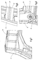
- the backrest structure 19 has substantially four interconnected at right angles, curved to open profiles areas, namely two side walls 21, a seat side rail 23 and a headrest side rail 25.
- the side walls 21 and the seat side rail 23 are bent in a C-shape or rolled so that the open side faces inwards.
- An example of such a spar 23 as used in the present embodiment is shown in FIG Fig. 11 shown in section.
- a small edge region is bent inward on the inside, the two edge regions being aligned with one another.
- the outside edges runs one outwards curved bead 21 "on one side from bottom to top and along the upper end of the side cheeks 21 at the other edge back down.
- a transverse connection 27 is welded between the two side walls on the inwardly bent edge regions of the C-shaped profile.
- the cross-connection 27 is presently by a rounded V-shaped bead 27 '(see Fig. 6 ) bent substantially rectangular punched and bent part formed of sheet metal of constant thickness, wherein the bead 27 'is directed towards the center of the backrest structure 19, so away from the corresponding side wall 21.
- Right and left of the bead 27' extend wing-like edge regions 27 ", which ensure a secure welded connection between the side wall 21 and the transverse connection 27.
- the longitudinal course of the bead 27 ' is directed substantially perpendicular to the two opposite outer surfaces of the C-profile forming the side wall 21. Furthermore, the transverse connection 27 is in the same height as one here the openings 21 'arranged in the side wall 21.
- the second adapter 17 of the corresponding fitting 7 is welded from the outside, wherein it is arranged between opposite beads 21 "(see FIG Fig. 3 ).
- the second adapter 17 is formed by a punched-bent part of a sheet of constant thickness, which has a first opening 17 'of circular cross section for the fitting 7 and a second opening 17 "with rounded rectangular cross section in the region of attachment to the side wall 21 and two on the longitudinal sides twice bent edges 17 "', which point to the outside when attached to the side wall 21.
- the width of the second adapter 17 decreases somewhat between the region in which the first opening 17 'and the area in which the second opening 17 "is arranged, wherein an approximately annular area with a width around the first opening 17' results.
- an area of approximately constant width is likewise provided, wherein the width (without consideration of the double-bent edge 17"'is approximately half the size of the width of the annular area (see FIG Fig. 5 ).
- the seat-side spar 23 is formed by a rectangular plate provided with a plurality of kinks in the longitudinal direction, having an approximately arcuate course (see Fig. 8 ). It is the end welded in the lower region of the side walls 21 with a protruding in the direction of the other side cheeks edge region thereof, ie in this area, the edge of the side cheeks 21 is not bent inwards again, as in the central region of the side cheeks, in which the cross connection 27th is provided.
- the headrest side rail 25 is also formed by a stamped and bent part, which is welded to projecting portions of the side walls 21.
- the spar 25 are u.a. Provided openings for the implementation of headrest legs. Furthermore, in the present case extending beads are provided transversely to the longitudinal direction.
- the second adapter 17 which instead of the second opening 17 "has a fork-like cutout 17"", ie the second opening is open at the top, headrest-side end of the adapter 17.
- the two tines have different lengths
- the tines arranged on the back of the backrest are longer than the tines arranged on the front side, and opposite longitudinal sides of the second adapter 17 are again provided with a double-bent edge 17 "'.
- the configuration of the headrest-side uprights 25, which is also formed by a punched-bent part of sheet metal, differs from that of the first exemplary embodiment, wherein the transversely extending beads are omitted in the spar and a longitudinal opening is provided.
- the first fitting part without first adapter directly to the seat part and the second fitting part without a second adapter are connected directly to the backrest structure.
- the embodiment corresponds to that of the first embodiment.
- the side cheeks and spars are formed profiled, and further cross connections are provided on the side cheeks, so that the stiffness curve can be optimized with respect to a torsional load and a bending load, in particular a most harmonious course of stiffness can be realized.
- the stiffness curve in this case preferably has no jump in stiffness, i. he is steady. Particularly preferred is a parabolic stiffness course is provided.
Landscapes
- Engineering & Computer Science (AREA)
- Aviation & Aerospace Engineering (AREA)
- Transportation (AREA)
- Mechanical Engineering (AREA)
- Seats For Vehicles (AREA)
- Chairs For Special Purposes, Such As Reclining Chairs (AREA)
Priority Applications (1)
| Application Number | Priority Date | Filing Date | Title |
|---|---|---|---|
| PL09745498T PL2276648T3 (pl) | 2008-05-13 | 2009-04-28 | Fotel pojazdu z okuciami |
Applications Claiming Priority (2)
| Application Number | Priority Date | Filing Date | Title |
|---|---|---|---|
| DE102008023943A DE102008023943B4 (de) | 2008-05-13 | 2008-05-13 | Fahrzeugsitz mit Beschlägen |
| PCT/EP2009/003058 WO2009138164A2 (de) | 2008-05-13 | 2009-04-28 | Fahrzeugsitz mit beschlägen |
Publications (2)
| Publication Number | Publication Date |
|---|---|
| EP2276648A2 EP2276648A2 (de) | 2011-01-26 |
| EP2276648B1 true EP2276648B1 (de) | 2014-03-12 |
Family
ID=40792473
Family Applications (1)
| Application Number | Title | Priority Date | Filing Date |
|---|---|---|---|
| EP09745498.7A Not-in-force EP2276648B1 (de) | 2008-05-13 | 2009-04-28 | Fahrzeugsitz mit beschlägen |
Country Status (7)
| Country | Link |
|---|---|
| US (1) | US8550563B2 (pl) |
| EP (1) | EP2276648B1 (pl) |
| CN (1) | CN102026844A (pl) |
| BR (1) | BRPI0912515A2 (pl) |
| DE (1) | DE102008023943B4 (pl) |
| PL (1) | PL2276648T3 (pl) |
| WO (1) | WO2009138164A2 (pl) |
Families Citing this family (16)
| Publication number | Priority date | Publication date | Assignee | Title |
|---|---|---|---|---|
| WO2011060219A1 (en) * | 2009-11-12 | 2011-05-19 | Johnson Controls Technology Company | One-piece seat back frame assembly and method of making same |
| DE102011102420B4 (de) * | 2011-05-24 | 2021-05-06 | Adient Luxembourg Holding S.À R.L. | Fahrzeugsitz, insbesondere Kraftfahrzeugsitz |
| DE202011105603U1 (de) | 2011-09-10 | 2011-10-24 | Keiper Gmbh & Co. Kg | Lehnenstruktur für einen Fahrzeugsitz |
| WO2013112787A1 (en) * | 2012-01-26 | 2013-08-01 | Johnson Controls Technology Company | Method for manufacturing a one-piece seat back structure |
| JP2013244872A (ja) * | 2012-05-28 | 2013-12-09 | Toyota Boshoku Corp | 車両用シートのシートバックフレーム構造 |
| DE102013003787B4 (de) * | 2012-11-30 | 2022-09-08 | Adient Us Llc | Fahrzeugsitz |
| CN108437866B (zh) * | 2012-12-28 | 2021-08-10 | 提爱思科技股份有限公司 | 座椅装置 |
| JP6215634B2 (ja) | 2013-09-30 | 2017-10-18 | トヨタ紡織株式会社 | 乗物用シートのシートフレーム |
| JP6218324B2 (ja) | 2014-01-29 | 2017-10-25 | 株式会社タチエス | 車両用シートのシートフレーム成形方法、シートフレームおよび車両用シート |
| CN104097005B (zh) * | 2014-07-04 | 2015-11-25 | 重庆格一机械制造有限公司 | 汽车后排座垫钢丝骨架的焊接夹具 |
| JP6617063B2 (ja) * | 2016-03-16 | 2019-12-04 | 株式会社タチエス | 車両用シート |
| DE102016115266B4 (de) * | 2016-08-17 | 2021-05-12 | Grammer Aktiengesellschaft | Vorrichtung mit Adapterelement und Verfahren zum Verbinden |
| JP6783621B2 (ja) * | 2016-10-26 | 2020-11-11 | 株式会社タチエス | 車両用シート |
| CN112711817B (zh) * | 2019-10-24 | 2023-04-28 | 深圳市建筑设计研究总院有限公司 | 一种受弯构件的支座连接方法 |
| US11440452B2 (en) * | 2020-10-27 | 2022-09-13 | Ford Global Technologies, Llc | Composite seat back |
| EP4674684A1 (en) * | 2024-07-04 | 2026-01-07 | Franz Kiel GmbH | Frame for a backrest of a passenger seat |
Citations (2)
| Publication number | Priority date | Publication date | Assignee | Title |
|---|---|---|---|---|
| FR2753935A1 (fr) * | 1996-10-02 | 1998-04-03 | Faure Bertrand Equipements Sa | Procede pour realiser un siege de vehicule, et siege realise selon ce procede |
| WO2006055616A1 (en) * | 2004-11-18 | 2006-05-26 | Johnson Controls Technology Company | Seat frame system and method of manufacturing |
Family Cites Families (31)
| Publication number | Priority date | Publication date | Assignee | Title |
|---|---|---|---|---|
| US2136122A (en) * | 1935-03-21 | 1938-11-08 | Midland Steel Prod Co | Chassis side rail |
| DE3239292A1 (de) * | 1981-11-11 | 1983-05-19 | Keiper Automobiltechnik Gmbh & Co Kg, 5630 Remscheid | Rueckenlehnenrahmen fuer sitze, insbesondere fuer kraftfahrzeugsitze |
| JPS6036797U (ja) * | 1983-08-19 | 1985-03-13 | 株式会社タチエス | サイサポ−ト装置付車両用シ−ト |
| DE3706394C1 (en) * | 1987-02-27 | 1988-05-11 | Audi Ag | Backrest for vehicle front seats |
| JPH0753556Y2 (ja) * | 1990-11-26 | 1995-12-13 | 池田物産株式会社 | バックフレーム |
| DE4436101C5 (de) | 1993-11-30 | 2008-12-11 | Keiper Gmbh & Co.Kg | Lehneneinstellbeschlag für Sitze mit verstellbarer Rückenlehne, insbesondere Kraftfahrzeugsitze |
| US5547259A (en) * | 1994-05-09 | 1996-08-20 | Mitchell Corporation Of Owosso, Inc. | Modular automotive seat frame |
| DE19500914A1 (de) * | 1995-01-13 | 1996-07-18 | Hammerstein Gmbh C Rob | Taumelgelenkbeschlag für einen verstellbaren Fahrzeugsitz |
| DE19603946C2 (de) * | 1996-02-05 | 1998-06-04 | Daimler Benz Ag | Fahrzeugsitz |
| US6233826B1 (en) * | 1997-07-21 | 2001-05-22 | Henkel Corp | Method for reinforcing structural members |
| JP3376887B2 (ja) * | 1997-10-13 | 2003-02-10 | トヨタ自動車株式会社 | 車両用シート |
| DE19826732B4 (de) * | 1998-06-16 | 2007-03-29 | Euromotive Ges.M.B.H. | Rücklehnenkonstruktion |
| DE19904300C1 (de) | 1999-01-28 | 2000-08-03 | Keiper Gmbh & Co | Rastbeschlag für einen Fahrzeugsitz |
| JP2000333768A (ja) * | 1999-05-31 | 2000-12-05 | Ikeda Bussan Co Ltd | シートバックフレーム |
| DE29910063U1 (de) * | 1999-06-09 | 2000-10-12 | Johnson Controls GmbH, 51399 Burscheid | Holmelement zur Kraftabstützung in einem Fahrzeug |
| US6149235A (en) * | 1999-08-13 | 2000-11-21 | Lear Corporation | Rotary-cam type reclining device |
| JP2001149176A (ja) * | 1999-11-29 | 2001-06-05 | Tachi S Co Ltd | シートバックフレーム構造 |
| JP4348808B2 (ja) * | 1999-12-27 | 2009-10-21 | トヨタ紡織株式会社 | 枠体に対する機能性部材の取付構造 |
| DE10105282B4 (de) | 2001-02-06 | 2005-03-24 | Keiper Gmbh & Co. Kg | Beschlag für einen Fahrzeugsitz |
| US6767055B1 (en) * | 2002-03-11 | 2004-07-27 | Bostrom Seating, Inc. | Vehicle seat frame and belt assembly |
| DE10219199A1 (de) * | 2002-04-29 | 2003-11-06 | Hammerstein Gmbh C Rob | Lehnengelenkbeschlag für einen Kraftfahrzeugsitz |
| US20040113481A1 (en) * | 2002-09-13 | 2004-06-17 | Mohammad Saberan | Vehicle seat frame |
| US6857698B2 (en) * | 2003-02-21 | 2005-02-22 | Lear Corporation | Seat side impact resistance mechanism |
| JP2005186670A (ja) * | 2003-12-24 | 2005-07-14 | Delta Kogyo Co Ltd | 車両用シート |
| US7255400B2 (en) * | 2004-02-23 | 2007-08-14 | Intier Automotive Inc. | Tubeless headrest support system |
| JP4916155B2 (ja) * | 2004-12-28 | 2012-04-11 | デルタ工業株式会社 | リクライニング装置 |
| JP4704116B2 (ja) * | 2005-06-07 | 2011-06-15 | 難波プレス工業株式会社 | 座席 |
| JP2007111340A (ja) | 2005-10-21 | 2007-05-10 | Inagaki:Kk | 背荷物受け付き椅子 |
| JP4643480B2 (ja) * | 2006-03-23 | 2011-03-02 | トヨタ自動車株式会社 | 車両用シートバックフレーム |
| DE102006036935A1 (de) * | 2006-08-08 | 2007-10-31 | Twb-Presswerk Gmbh & Co. Kg | Rückenlehne für eine Sitzbank eines Fahrzeuges |
| DE102007016690A1 (de) * | 2006-10-27 | 2008-04-30 | Johnson Controls Gmbh | Strukturelement für Fahrzeugsitz |
-
2008
- 2008-05-13 DE DE102008023943A patent/DE102008023943B4/de not_active Expired - Fee Related
-
2009
- 2009-04-28 PL PL09745498T patent/PL2276648T3/pl unknown
- 2009-04-28 CN CN2009801170863A patent/CN102026844A/zh active Pending
- 2009-04-28 US US12/863,079 patent/US8550563B2/en not_active Expired - Fee Related
- 2009-04-28 EP EP09745498.7A patent/EP2276648B1/de not_active Not-in-force
- 2009-04-28 BR BRPI0912515A patent/BRPI0912515A2/pt not_active IP Right Cessation
- 2009-04-28 WO PCT/EP2009/003058 patent/WO2009138164A2/de not_active Ceased
Patent Citations (2)
| Publication number | Priority date | Publication date | Assignee | Title |
|---|---|---|---|---|
| FR2753935A1 (fr) * | 1996-10-02 | 1998-04-03 | Faure Bertrand Equipements Sa | Procede pour realiser un siege de vehicule, et siege realise selon ce procede |
| WO2006055616A1 (en) * | 2004-11-18 | 2006-05-26 | Johnson Controls Technology Company | Seat frame system and method of manufacturing |
Also Published As
| Publication number | Publication date |
|---|---|
| PL2276648T3 (pl) | 2014-08-29 |
| BRPI0912515A2 (pt) | 2019-09-24 |
| US8550563B2 (en) | 2013-10-08 |
| US20110043022A1 (en) | 2011-02-24 |
| DE102008023943B4 (de) | 2012-03-15 |
| CN102026844A (zh) | 2011-04-20 |
| WO2009138164A2 (de) | 2009-11-19 |
| EP2276648A2 (de) | 2011-01-26 |
| WO2009138164A3 (de) | 2010-05-06 |
| DE102008023943A1 (de) | 2009-11-19 |
Similar Documents
| Publication | Publication Date | Title |
|---|---|---|
| EP2276648B1 (de) | Fahrzeugsitz mit beschlägen | |
| EP2925562B1 (de) | Fahrzeugsitz | |
| EP2376309B1 (de) | Fahrzeugsitz, insbesondere kraftfahrzeugsitz | |
| DE102013204249A1 (de) | Fahrzeugsitz | |
| EP2057032A1 (de) | Fahrzeugsitz, insbesondere nutzfahrzeugsitz | |
| WO2013110528A1 (de) | Hilfsrahmen für ein kraftfahrzeug | |
| DE202014102248U1 (de) | Verbindung eines Rahmenlängsträgers und einer Säule eines Fahrszeugs | |
| DE112015000063B4 (de) | Fahrzeugkarosserie mit Öffnung in einem Fahrzeugkarosserie-Heckabschnitt | |
| EP1654150A1 (de) | Knotenstruktur zur verbindung von zwei profilen in einem fahrzeugtragrahmen | |
| DE102007007296A1 (de) | Fahrzeugsitz, insbesondere Kraftfahrzeugsitz | |
| EP0140177A2 (de) | Fahrzeugsitz | |
| DE102010006669B4 (de) | Profilknoten für eine Fahrzeugkarosserie | |
| DE102016106720B4 (de) | Fahrzeugfrontstruktur | |
| DE202014103332U1 (de) | Bodenbaugruppe für Fahrzeuge und Fahrzeug mit einer solchen Bodenbaugruppe | |
| WO2012052088A1 (de) | Fahrzeugsitz, insbesondere kraftfahrzeugsitz | |
| EP3539818B1 (de) | Gurtgestell für einen fahrzeugsitz oder eine fahrzeugsitzbank und fahrzeug-sitzanordnung | |
| DE202008002339U1 (de) | Fahrzeugsitz, insbesondere Nutzfahrzeugsitz | |
| DE112012004351B4 (de) | Sitz mit verschweißter Querwelle | |
| EP2838759B1 (de) | Trägerstruktur für eine armlehne eines fahrzeugs | |
| EP4321378A2 (de) | Rahmen für einen fahrzeugsitz und fahrzeugsitz mit einem selbigen | |
| DE19905295B4 (de) | Befestigungsstruktur für eine Fahrzeugsitz-Rückenlehne | |
| DE202022101820U1 (de) | Rückenlehne eines Fahrzeugsitzes, Fahrzeugsitz, der eine solche Rückenlehne umfasst und Sitzbaugruppe, die einen solchen Sitz umfasst | |
| DE102016117886A1 (de) | Vorrichtung zur Anordnung eines Personenrückhaltesystems in einem Verkehrsmittel, Personensitzanordnung und Verkehrsmittel | |
| EP3238987B1 (de) | Vorrichtung zur anordnung eines personenrückhaltesystems in einem verkehrsmittel, personensitzanordnung und verkehrsmittel | |
| DE202011105603U1 (de) | Lehnenstruktur für einen Fahrzeugsitz |
Legal Events
| Date | Code | Title | Description |
|---|---|---|---|
| PUAI | Public reference made under article 153(3) epc to a published international application that has entered the european phase |
Free format text: ORIGINAL CODE: 0009012 |
|
| 17P | Request for examination filed |
Effective date: 20100928 |
|
| AK | Designated contracting states |
Kind code of ref document: A2 Designated state(s): AT BE BG CH CY CZ DE DK EE ES FI FR GB GR HR HU IE IS IT LI LT LU LV MC MK MT NL NO PL PT RO SE SI SK TR |
|
| DAX | Request for extension of the european patent (deleted) | ||
| 17Q | First examination report despatched |
Effective date: 20130208 |
|
| GRAP | Despatch of communication of intention to grant a patent |
Free format text: ORIGINAL CODE: EPIDOSNIGR1 |
|
| INTG | Intention to grant announced |
Effective date: 20131023 |
|
| GRAS | Grant fee paid |
Free format text: ORIGINAL CODE: EPIDOSNIGR3 |
|
| GRAA | (expected) grant |
Free format text: ORIGINAL CODE: 0009210 |
|
| AK | Designated contracting states |
Kind code of ref document: B1 Designated state(s): AT BE BG CH CY CZ DE DK EE ES FI FR GB GR HR HU IE IS IT LI LT LU LV MC MK MT NL NO PL PT RO SE SI SK TR |
|
| REG | Reference to a national code |
Ref country code: GB Ref legal event code: FG4D Free format text: NOT ENGLISH |
|
| REG | Reference to a national code |
Ref country code: CH Ref legal event code: EP |
|
| REG | Reference to a national code |
Ref country code: AT Ref legal event code: REF Ref document number: 656041 Country of ref document: AT Kind code of ref document: T Effective date: 20140315 |
|
| REG | Reference to a national code |
Ref country code: IE Ref legal event code: FG4D Free format text: LANGUAGE OF EP DOCUMENT: GERMAN |
|
| REG | Reference to a national code |
Ref country code: DE Ref legal event code: R096 Ref document number: 502009008982 Country of ref document: DE Effective date: 20140424 |
|
| REG | Reference to a national code |
Ref country code: NL Ref legal event code: VDEP Effective date: 20140312 |
|
| PG25 | Lapsed in a contracting state [announced via postgrant information from national office to epo] |
Ref country code: LT Free format text: LAPSE BECAUSE OF FAILURE TO SUBMIT A TRANSLATION OF THE DESCRIPTION OR TO PAY THE FEE WITHIN THE PRESCRIBED TIME-LIMIT Effective date: 20140312 Ref country code: NO Free format text: LAPSE BECAUSE OF FAILURE TO SUBMIT A TRANSLATION OF THE DESCRIPTION OR TO PAY THE FEE WITHIN THE PRESCRIBED TIME-LIMIT Effective date: 20140612 |
|
| REG | Reference to a national code |
Ref country code: SK Ref legal event code: T3 Ref document number: E 16263 Country of ref document: SK |
|
| REG | Reference to a national code |
Ref country code: DE Ref legal event code: R081 Ref document number: 502009008982 Country of ref document: DE Owner name: JOHNSON CONTROLS COMPONENTS GMBH & CO. KG, DE Free format text: FORMER OWNER: KEIPER GMBH & CO. KG, 67657 KAISERSLAUTERN, DE Effective date: 20140710 Ref country code: DE Ref legal event code: R081 Ref document number: 502009008982 Country of ref document: DE Owner name: ADIENT LUXEMBOURG HOLDING S.A.R.L., LU Free format text: FORMER OWNER: KEIPER GMBH & CO. KG, 67657 KAISERSLAUTERN, DE Effective date: 20140710 Ref country code: DE Ref legal event code: R081 Ref document number: 502009008982 Country of ref document: DE Owner name: ADIENT LUXEMBOURG HOLDING S.A R.L., LU Free format text: FORMER OWNER: KEIPER GMBH & CO. KG, 67657 KAISERSLAUTERN, DE Effective date: 20140710 |
|
| REG | Reference to a national code |
Ref country code: LT Ref legal event code: MG4D |
|
| PG25 | Lapsed in a contracting state [announced via postgrant information from national office to epo] |
Ref country code: CY Free format text: LAPSE BECAUSE OF FAILURE TO SUBMIT A TRANSLATION OF THE DESCRIPTION OR TO PAY THE FEE WITHIN THE PRESCRIBED TIME-LIMIT Effective date: 20140312 Ref country code: SE Free format text: LAPSE BECAUSE OF FAILURE TO SUBMIT A TRANSLATION OF THE DESCRIPTION OR TO PAY THE FEE WITHIN THE PRESCRIBED TIME-LIMIT Effective date: 20140312 Ref country code: FI Free format text: LAPSE BECAUSE OF FAILURE TO SUBMIT A TRANSLATION OF THE DESCRIPTION OR TO PAY THE FEE WITHIN THE PRESCRIBED TIME-LIMIT Effective date: 20140312 |
|
| REG | Reference to a national code |
Ref country code: PL Ref legal event code: T3 |
|
| RAP2 | Party data changed (patent owner data changed or rights of a patent transferred) |
Owner name: JOHNSON CONTROLS COMPONENTS GMBH & CO. KG |
|
| PG25 | Lapsed in a contracting state [announced via postgrant information from national office to epo] |
Ref country code: HR Free format text: LAPSE BECAUSE OF FAILURE TO SUBMIT A TRANSLATION OF THE DESCRIPTION OR TO PAY THE FEE WITHIN THE PRESCRIBED TIME-LIMIT Effective date: 20140312 Ref country code: LV Free format text: LAPSE BECAUSE OF FAILURE TO SUBMIT A TRANSLATION OF THE DESCRIPTION OR TO PAY THE FEE WITHIN THE PRESCRIBED TIME-LIMIT Effective date: 20140312 |
|
| PG25 | Lapsed in a contracting state [announced via postgrant information from national office to epo] |
Ref country code: RO Free format text: LAPSE BECAUSE OF FAILURE TO SUBMIT A TRANSLATION OF THE DESCRIPTION OR TO PAY THE FEE WITHIN THE PRESCRIBED TIME-LIMIT Effective date: 20140312 Ref country code: NL Free format text: LAPSE BECAUSE OF FAILURE TO SUBMIT A TRANSLATION OF THE DESCRIPTION OR TO PAY THE FEE WITHIN THE PRESCRIBED TIME-LIMIT Effective date: 20140312 Ref country code: IS Free format text: LAPSE BECAUSE OF FAILURE TO SUBMIT A TRANSLATION OF THE DESCRIPTION OR TO PAY THE FEE WITHIN THE PRESCRIBED TIME-LIMIT Effective date: 20140712 Ref country code: BG Free format text: LAPSE BECAUSE OF FAILURE TO SUBMIT A TRANSLATION OF THE DESCRIPTION OR TO PAY THE FEE WITHIN THE PRESCRIBED TIME-LIMIT Effective date: 20140612 Ref country code: EE Free format text: LAPSE BECAUSE OF FAILURE TO SUBMIT A TRANSLATION OF THE DESCRIPTION OR TO PAY THE FEE WITHIN THE PRESCRIBED TIME-LIMIT Effective date: 20140312 |
|
| PG25 | Lapsed in a contracting state [announced via postgrant information from national office to epo] |
Ref country code: ES Free format text: LAPSE BECAUSE OF FAILURE TO SUBMIT A TRANSLATION OF THE DESCRIPTION OR TO PAY THE FEE WITHIN THE PRESCRIBED TIME-LIMIT Effective date: 20140312 Ref country code: MC Free format text: LAPSE BECAUSE OF FAILURE TO SUBMIT A TRANSLATION OF THE DESCRIPTION OR TO PAY THE FEE WITHIN THE PRESCRIBED TIME-LIMIT Effective date: 20140312 |
|
| REG | Reference to a national code |
Ref country code: CH Ref legal event code: PL |
|
| REG | Reference to a national code |
Ref country code: DE Ref legal event code: R097 Ref document number: 502009008982 Country of ref document: DE |
|
| PG25 | Lapsed in a contracting state [announced via postgrant information from national office to epo] |
Ref country code: PT Free format text: LAPSE BECAUSE OF FAILURE TO SUBMIT A TRANSLATION OF THE DESCRIPTION OR TO PAY THE FEE WITHIN THE PRESCRIBED TIME-LIMIT Effective date: 20140714 |
|
| PLBE | No opposition filed within time limit |
Free format text: ORIGINAL CODE: 0009261 |
|
| STAA | Information on the status of an ep patent application or granted ep patent |
Free format text: STATUS: NO OPPOSITION FILED WITHIN TIME LIMIT |
|
| REG | Reference to a national code |
Ref country code: IE Ref legal event code: MM4A |
|
| PG25 | Lapsed in a contracting state [announced via postgrant information from national office to epo] |
Ref country code: DK Free format text: LAPSE BECAUSE OF FAILURE TO SUBMIT A TRANSLATION OF THE DESCRIPTION OR TO PAY THE FEE WITHIN THE PRESCRIBED TIME-LIMIT Effective date: 20140312 Ref country code: CH Free format text: LAPSE BECAUSE OF NON-PAYMENT OF DUE FEES Effective date: 20140430 Ref country code: LI Free format text: LAPSE BECAUSE OF NON-PAYMENT OF DUE FEES Effective date: 20140430 |
|
| 26N | No opposition filed |
Effective date: 20141215 |
|
| GBPC | Gb: european patent ceased through non-payment of renewal fee |
Effective date: 20140612 |
|
| REG | Reference to a national code |
Ref country code: DE Ref legal event code: R097 Ref document number: 502009008982 Country of ref document: DE Effective date: 20141215 |
|
| PG25 | Lapsed in a contracting state [announced via postgrant information from national office to epo] |
Ref country code: IT Free format text: LAPSE BECAUSE OF FAILURE TO SUBMIT A TRANSLATION OF THE DESCRIPTION OR TO PAY THE FEE WITHIN THE PRESCRIBED TIME-LIMIT Effective date: 20140312 |
|
| PG25 | Lapsed in a contracting state [announced via postgrant information from national office to epo] |
Ref country code: IE Free format text: LAPSE BECAUSE OF NON-PAYMENT OF DUE FEES Effective date: 20140428 |
|
| PG25 | Lapsed in a contracting state [announced via postgrant information from national office to epo] |
Ref country code: GB Free format text: LAPSE BECAUSE OF NON-PAYMENT OF DUE FEES Effective date: 20140612 |
|
| REG | Reference to a national code |
Ref country code: AT Ref legal event code: MM01 Ref document number: 656041 Country of ref document: AT Kind code of ref document: T Effective date: 20140428 |
|
| PG25 | Lapsed in a contracting state [announced via postgrant information from national office to epo] |
Ref country code: SI Free format text: LAPSE BECAUSE OF FAILURE TO SUBMIT A TRANSLATION OF THE DESCRIPTION OR TO PAY THE FEE WITHIN THE PRESCRIBED TIME-LIMIT Effective date: 20140312 |
|
| PG25 | Lapsed in a contracting state [announced via postgrant information from national office to epo] |
Ref country code: AT Free format text: LAPSE BECAUSE OF NON-PAYMENT OF DUE FEES Effective date: 20140428 |
|
| PG25 | Lapsed in a contracting state [announced via postgrant information from national office to epo] |
Ref country code: MT Free format text: LAPSE BECAUSE OF FAILURE TO SUBMIT A TRANSLATION OF THE DESCRIPTION OR TO PAY THE FEE WITHIN THE PRESCRIBED TIME-LIMIT Effective date: 20140312 |
|
| REG | Reference to a national code |
Ref country code: FR Ref legal event code: PLFP Year of fee payment: 8 |
|
| PG25 | Lapsed in a contracting state [announced via postgrant information from national office to epo] |
Ref country code: GR Free format text: LAPSE BECAUSE OF FAILURE TO SUBMIT A TRANSLATION OF THE DESCRIPTION OR TO PAY THE FEE WITHIN THE PRESCRIBED TIME-LIMIT Effective date: 20140613 |
|
| PG25 | Lapsed in a contracting state [announced via postgrant information from national office to epo] |
Ref country code: TR Free format text: LAPSE BECAUSE OF FAILURE TO SUBMIT A TRANSLATION OF THE DESCRIPTION OR TO PAY THE FEE WITHIN THE PRESCRIBED TIME-LIMIT Effective date: 20140312 Ref country code: HU Free format text: LAPSE BECAUSE OF FAILURE TO SUBMIT A TRANSLATION OF THE DESCRIPTION OR TO PAY THE FEE WITHIN THE PRESCRIBED TIME-LIMIT; INVALID AB INITIO Effective date: 20090428 Ref country code: BE Free format text: LAPSE BECAUSE OF FAILURE TO SUBMIT A TRANSLATION OF THE DESCRIPTION OR TO PAY THE FEE WITHIN THE PRESCRIBED TIME-LIMIT Effective date: 20140430 Ref country code: LU Free format text: LAPSE BECAUSE OF NON-PAYMENT OF DUE FEES Effective date: 20140428 |
|
| REG | Reference to a national code |
Ref country code: DE Ref legal event code: R081 Ref document number: 502009008982 Country of ref document: DE Owner name: ADIENT LUXEMBOURG HOLDING S.A.R.L., LU Free format text: FORMER OWNER: JOHNSON CONTROLS COMPONENTS GMBH & CO. KG, 67657 KAISERSLAUTERN, DE Ref country code: DE Ref legal event code: R081 Ref document number: 502009008982 Country of ref document: DE Owner name: ADIENT LUXEMBOURG HOLDING S.A R.L., LU Free format text: FORMER OWNER: JOHNSON CONTROLS COMPONENTS GMBH & CO. KG, 67657 KAISERSLAUTERN, DE |
|
| REG | Reference to a national code |
Ref country code: FR Ref legal event code: PLFP Year of fee payment: 9 |
|
| PGFP | Annual fee paid to national office [announced via postgrant information from national office to epo] |
Ref country code: CZ Payment date: 20170324 Year of fee payment: 9 |
|
| PGFP | Annual fee paid to national office [announced via postgrant information from national office to epo] |
Ref country code: SK Payment date: 20170425 Year of fee payment: 9 |
|
| PGFP | Annual fee paid to national office [announced via postgrant information from national office to epo] |
Ref country code: PL Payment date: 20170425 Year of fee payment: 9 |
|
| REG | Reference to a national code |
Ref country code: DE Ref legal event code: R081 Ref document number: 502009008982 Country of ref document: DE Owner name: ADIENT LUXEMBOURG HOLDING S.A R.L., LU Free format text: FORMER OWNER: ADIENT LUXEMBOURG HOLDING S.A.R.L., LUXEMBOURG, LU |
|
| REG | Reference to a national code |
Ref country code: FR Ref legal event code: PLFP Year of fee payment: 10 |
|
| PG25 | Lapsed in a contracting state [announced via postgrant information from national office to epo] |
Ref country code: MK Free format text: LAPSE BECAUSE OF FAILURE TO SUBMIT A TRANSLATION OF THE DESCRIPTION OR TO PAY THE FEE WITHIN THE PRESCRIBED TIME-LIMIT Effective date: 20140312 |
|
| PGFP | Annual fee paid to national office [announced via postgrant information from national office to epo] |
Ref country code: DE Payment date: 20180430 Year of fee payment: 10 |
|
| REG | Reference to a national code |
Ref country code: SK Ref legal event code: MM4A Ref document number: E 16263 Country of ref document: SK Effective date: 20180428 |
|
| PG25 | Lapsed in a contracting state [announced via postgrant information from national office to epo] |
Ref country code: SK Free format text: LAPSE BECAUSE OF NON-PAYMENT OF DUE FEES Effective date: 20180428 Ref country code: CZ Free format text: LAPSE BECAUSE OF NON-PAYMENT OF DUE FEES Effective date: 20180428 |
|
| PGFP | Annual fee paid to national office [announced via postgrant information from national office to epo] |
Ref country code: FR Payment date: 20190418 Year of fee payment: 11 |
|
| REG | Reference to a national code |
Ref country code: DE Ref legal event code: R119 Ref document number: 502009008982 Country of ref document: DE |
|
| PG25 | Lapsed in a contracting state [announced via postgrant information from national office to epo] |
Ref country code: PL Free format text: LAPSE BECAUSE OF NON-PAYMENT OF DUE FEES Effective date: 20180428 |
|
| PG25 | Lapsed in a contracting state [announced via postgrant information from national office to epo] |
Ref country code: DE Free format text: LAPSE BECAUSE OF NON-PAYMENT OF DUE FEES Effective date: 20191101 |
|
| PG25 | Lapsed in a contracting state [announced via postgrant information from national office to epo] |
Ref country code: FR Free format text: LAPSE BECAUSE OF NON-PAYMENT OF DUE FEES Effective date: 20200430 |