EP2276648B1 - Vehicle seat comprising fixtures - Google Patents
Vehicle seat comprising fixtures Download PDFInfo
- Publication number
- EP2276648B1 EP2276648B1 EP09745498.7A EP09745498A EP2276648B1 EP 2276648 B1 EP2276648 B1 EP 2276648B1 EP 09745498 A EP09745498 A EP 09745498A EP 2276648 B1 EP2276648 B1 EP 2276648B1
- Authority
- EP
- European Patent Office
- Prior art keywords
- vehicle seat
- lateral cheeks
- adapter
- seat according
- bent
- Prior art date
- Legal status (The legal status is an assumption and is not a legal conclusion. Google has not performed a legal analysis and makes no representation as to the accuracy of the status listed.)
- Not-in-force
Links
- 239000011324 bead Substances 0.000 claims description 16
- 239000002184 metal Substances 0.000 claims description 6
- 238000005452 bending Methods 0.000 description 7
- 239000000463 material Substances 0.000 description 4
- 230000003014 reinforcing effect Effects 0.000 description 2
- 238000003466 welding Methods 0.000 description 2
- 235000003332 Ilex aquifolium Nutrition 0.000 description 1
- 241000209027 Ilex aquifolium Species 0.000 description 1
- 230000005540 biological transmission Effects 0.000 description 1
- 230000007423 decrease Effects 0.000 description 1
- 230000001419 dependent effect Effects 0.000 description 1
- 230000003993 interaction Effects 0.000 description 1
- 230000004048 modification Effects 0.000 description 1
- 238000012986 modification Methods 0.000 description 1
- 230000002787 reinforcement Effects 0.000 description 1
- IHQKEDIOMGYHEB-UHFFFAOYSA-M sodium dimethylarsinate Chemical class [Na+].C[As](C)([O-])=O IHQKEDIOMGYHEB-UHFFFAOYSA-M 0.000 description 1
Images


Classifications
-
- B—PERFORMING OPERATIONS; TRANSPORTING
- B60—VEHICLES IN GENERAL
- B60N—SEATS SPECIALLY ADAPTED FOR VEHICLES; VEHICLE PASSENGER ACCOMMODATION NOT OTHERWISE PROVIDED FOR
- B60N2/00—Seats specially adapted for vehicles; Arrangement or mounting of seats in vehicles
- B60N2/68—Seat frames
- B60N2/682—Joining means
-
- B—PERFORMING OPERATIONS; TRANSPORTING
- B60—VEHICLES IN GENERAL
- B60N—SEATS SPECIALLY ADAPTED FOR VEHICLES; VEHICLE PASSENGER ACCOMMODATION NOT OTHERWISE PROVIDED FOR
- B60N2/00—Seats specially adapted for vehicles; Arrangement or mounting of seats in vehicles
- B60N2/02—Seats specially adapted for vehicles; Arrangement or mounting of seats in vehicles the seat or part thereof being movable, e.g. adjustable
- B60N2/22—Seats specially adapted for vehicles; Arrangement or mounting of seats in vehicles the seat or part thereof being movable, e.g. adjustable the back-rest being adjustable
-
- B—PERFORMING OPERATIONS; TRANSPORTING
- B60—VEHICLES IN GENERAL
- B60N—SEATS SPECIALLY ADAPTED FOR VEHICLES; VEHICLE PASSENGER ACCOMMODATION NOT OTHERWISE PROVIDED FOR
- B60N2/00—Seats specially adapted for vehicles; Arrangement or mounting of seats in vehicles
- B60N2/68—Seat frames
Landscapes
- Engineering & Computer Science (AREA)
- Aviation & Aerospace Engineering (AREA)
- Transportation (AREA)
- Mechanical Engineering (AREA)
- Seats For Vehicles (AREA)
- Chairs For Special Purposes, Such As Reclining Chairs (AREA)
Description
Die Erfindung betrifft einen Fahrzeugsitz, insbesondere Kraftfahrzeugsitz, mit Beschlägen gemäß dem Oberbegriff des Anspruches 1.The invention relates to a vehicle seat, in particular a motor vehicle seat, with fittings according to the preamble of
Aus der
Die
Die
Aus der
Weiterhin sind aus der
Der Erfindung liegt die Aufgabe zu Grunde, einen Fahrzeugsitz mit Beschlägen der eingangs genannten Art zu verbessern, insbesondere die Steifigkeit zu erhöhen. Diese Aufgabe wird erfindungsgemäß durch einen Fahrzeugsitz mit den Merkmalen des Anspruches 1 gelöst. Vorteilhafte Ausgestaltungen sind Gegenstand der Unteransprüche.The invention is based on the object to improve a vehicle seat with fittings of the type mentioned, in particular to increase the rigidity. This object is achieved by a vehicle seat with the features of
Die Verwendung eines Fahrzeugsitzes, insbesondere eines Kraftfahrzeugsitzes, mit Beschlägen, aufweisend ein erstes Beschlagteil und ein zweites Beschlagteil, und einer Lehnenstruktur mit Seitenwangen und mindestens einem die Seitenwangen verbindenden Holm, wobei die Seitenwangen der Lehnenstruktur durch offene Profile gebildet sind, und das offene Profil der Seitenwangen in einem mittleren Bereich durch eine Querverbindung geschlossen ist, ermöglicht eine Optimierung der Biegesteifigkeit der Lehne. Die Querverbindung ist bevorzugt an die entsprechende Seitenwange angeschweißt. Die Querverbindung erhöht zudem die Torsionssteifigkeit der Seitenwange, welche im Falle einer Krafteinleitung über eine Kopfstütze relevant ist. Die Querverbindung stellt zudem sicher, dass im Falle eines Seitenaufpralls die Rippen des Insassen nicht ins Innere des durch die Seitenwangen gebildeten, nach innen offenen C-Profils gelangen, so dass der Insasse auch im Falle eines Seitenaufpralls geschützt ist.The use of a vehicle seat, in particular a motor vehicle seat, with fittings, comprising a first fitting part and a second fitting part, and a backrest structure with side cheeks and at least one spar connecting the side cheeks, wherein the side cheeks of the backrest structure are formed by open profiles, and the open profile of Side cheeks in a central region is closed by a cross-connection, allows to optimize the flexural rigidity of the backrest. The cross connection is preferably welded to the corresponding side cheek. The cross connection also increases the torsional rigidity of the side cheek, which is relevant in the case of a force introduction via a headrest. The cross-connection also ensures that in the event of a side impact, the occupant's ribs do not enter the interior of the C-profile formed by the side cheeks, so that the occupant is protected even in the event of a side impact.
Insbesondere können dabei erste Beschlagteil ohne ersten Adapter direkt mit dem Sitzteil und/oder das zweite Beschlagteil ohne zweiten Adapter direkt mit der Lehnenstruktur verbunden sein.In particular, the first fitting part without a first adapter can be connected directly to the seat part and / or the second fitting part without a second adapter directly to the backrest structure.
Insbesondere bevorzugt ist - ohne Berücksichtigung von insbesondere verbindungstechnisch bedingten Querverbindung im Bereich der Anbringung von kopfstützenseitigen und/oder sitzseitigen Holmen zwischen den Seitenwangen - ausschließlich eine Querverbindung vorgesehen, d.h. abgesehen von ggf. vorhandenen endseitigen Querverbindungen und besagter einer im mittleren Bereich vorgesehenen Querverbindung ist das Profil offen ausgebildet.Particularly preferred is - without consideration of particular connection-related cross-connection in the field of attachment of headrest side and / or seat side bars between the side walls - only a cross-connection provided, i. Apart from possibly existing end cross-connections and said one provided in the central region cross-connection, the profile is open.
Erfindungsgemäß weisen die Seitenwangen entlang ihrer Längsrichtung beidseitig einen zweifach um 90° gebogenen Randbereich sowie mindestens einen Durchbruch, insbesondere bevorzugt eine Reihe von mehreren Durchbrüchen, im mittleren Bereich entlang der Mittellängslinie der Seitenwangen auf. Der zweifach umgebogene Randbereich ermöglicht eine einfache Anbringung der Querverbindung, insbesondere mittels Schweißens. Durch das Vorsehen mindestens eines, bevorzugt mehrerer Durchbrüche entlang der Mittellängslinie der Seitenwangen lässt sich Material und Gewicht einsparen, wobei die durch die Materialersparnis verringerte Biegesteifigkeit durch die Querverbindung ausgleichbar ist. Insbesondere durch das Zusammenspiel von Durchbrüchen und Querverbindung lässt sich über die Lehnenhöhe eine in jedem Bereich optimierte Biegesteifigkeit der Lehne erzielen. Auch die Torsionssteifigkeit kann durch diese Maßnahmen optimiert werden.According to the invention, the side cheeks along their longitudinal direction on both sides of a double bent by 90 ° edge region and at least one breakthrough, more preferably a series of multiple openings in the central region along the median longitudinal line of the side cheeks. The double bent over Edge area allows easy attachment of the cross connection, in particular by welding. By providing at least one, preferably a plurality of openings along the central longitudinal line of the side cheeks, material and weight can be saved, wherein the bending stiffness reduced by the material savings can be compensated for by the transverse connection. In particular, through the interaction of openings and cross-connection can be achieved on the backrest height optimized in each area bending stiffness of the backrest. The torsional stiffness can be optimized by these measures.
Bei der Querverbindung handelt es sich dabei um ein Stanz-Biegeteil aus Blech, welches mindestens eine Sicke, insbesondere bevorzugt genau eine Sicke, und ein oder mehrere, insbesondere zwei, sich seitlich nach außen erstreckende flügelartige Bereiche aufweist. Die Sicke gibt dem Blech auch bei geringen Blechstärken eine ausreichende Biegesteifigkeit, so dass die zu erwartenden Belastungen gut aufgenommen werden können. Die Sicke der Querverbindung verläuft bevorzugt im Mittel senkrecht zu und/oder in Bezug auf mindestens eine der vorderen und hinteren Seitenflächen der Seitenwangen.The cross-connection is a punched-bent part made of sheet metal, which has at least one bead, particularly preferably exactly one bead, and one or more, in particular two, wing-like regions extending laterally outwards. The beading gives the sheet sufficient bending stiffness even at low sheet thicknesses, so that the expected loads can be well absorbed. The bead of the transverse connection preferably extends perpendicularly to the center and / or with respect to at least one of the front and rear side surfaces of the side cheeks.
Vorzugsweise sind die Seitenwangen am sitzseitigen Ende über einen sitzseitigen und/oder einen kopflehnenseitigen Holm miteinander verbunden, wobei der Holm durch ein Stanz-Biegeteil gebildet ist. Die Holme sind besonders bevorzugt mit den Seitenwangen mittels Schweißverbindungen fest verbunden, jedoch sind auch andere Verbindungen, wie beispielsweise Niet-, Schraub-, Steck- oder Clipsverbindungen denkbar.Preferably, the side cheeks are connected to each other at the seat-side end via a seat-side and / or a headrest-side spar, wherein the spar is formed by a stamped and bent part. The spars are particularly preferably firmly connected to the side walls by means of welded joints, but other connections, such as rivet, screw, plug or clip connections are conceivable.
Die Seitenwangen können mit den Beschlägen über Adapter verbunden sein, wobei der Adapter einen kreisförmigen Durchbruch und entlang beiden Längsseiten einen umgebogenen Rand aufweist. Der umgebogene Rand erhöht die Biegesteifigkeit und stellt sicher, dass der Adapter auch bereits vor der Anbringung an den Seitenwangen nicht verbogen wird und eine flächige Anlage gewährleistet werden kann. Die Verbindung erfolgt bevorzugt mittels einer Schweißverbindung, insbesondere mittels einzelner Schweißpunkte oder Schweißraupen, besonders bevorzugt mittels CMT(cold metal transfer)-Schweißens geschweißt. Natürlich ist auch eine direkte Anbringung ohne Adapter möglich.The side cheeks may be connected to the fittings via adapters, the adapter having a circular aperture and along both longitudinal sides a bent edge. The bent edge increases the bending stiffness and ensures that the adapter is not bent even before attachment to the side walls and a flat system can be ensured. The connection is preferably carried out by means of a welded connection, in particular by means of individual spot welds or weld beads, particularly preferably by means of CMT (cold metal transfer) welding. Of course, a direct attachment without adapter is possible.
Der Adapter weist vorzugsweise einen zweiten Durchbruch oder einen Ausschnitt auf, welcher zwischen den umgebogenen Rändern verlaufend ausgebildet ist. Durch diesen Durchbruch bzw. Ausschnitt kann zum Einen Material eingespart werden. Zum Anderen kann durch die Gestalt des Durchbruchs bzw. Ausschnitts Einfluss auf die Biegesteifigkeit genommen werden. Auch erhöhen die entsprechend ausgebildeten Adapter die Torsionssteifigkeit der Seitenwangen im unteren Bereich, so dass die Verformung der Lehnenstruktur insgesamt verringert werden kann, insbesondere bevorzugt ohne dass das Gewicht derselben erhöht werden muss.The adapter preferably has a second opening or a cutout, which is designed to extend between the bent edges. Through this breakthrough or cutout can be saved on the one material. On the other hand, the shape of the opening or cut-out can influence the bending stiffness. The correspondingly formed adapters also increase the torsional rigidity of the side cheeks in the lower region, so that the deformation of the backrest structure as a whole can be reduced, in particular preferably without the weight of the same having to be increased.
Sind sowohl Querverbindungen als auch entsprechend ausgebildete Adapter an den Seitenwangen vorgesehen, so lässt sich der Steifigkeitsverlauf in Bezug auf eine Torsionsbelastung und eine Biegebelastung optimieren, insbesondere lässt sich ein möglichst harmonischer Verlauf der Steifigkeit realisieren. Der Steifigkeitsverlauf weist hierbei bevorzugt keinen Steifigkeitssprung auf, d.h. er ist stetig. Insbesondere bevorzugt ist ein parabelförmiger Steifigkeitsverlauf vorgesehen.If both cross connections and appropriately designed adapters are provided on the side cheeks, then the stiffness curve can be optimized with respect to a torsional load and a bending load; in particular, the most harmonious course of the rigidity can be realized. The stiffness curve in this case preferably has no jump in stiffness, i. he is steady. Particularly preferred is a parabolic stiffness course is provided.
Der zweite Durchbruch ist besonders bevorzugt annähernd rechteckförmig ausgebildet, wobei die Eckbereiche abgerundet sind, jedoch kann die Gestalt auch am Ende offen ausgebildet sein, so dass sich eine Art Gabel ergibt.The second opening is particularly preferably formed approximately rectangular, wherein the corner regions are rounded, however, the shape may also be open at the end, so that there is a kind of fork.
Die Erfindung ist beispielsweise bei lähgseinstellbaren Fahrzeugsitzen von zweitürigen Kraftfahrzeugen mit zentrischem Freischwenken der Lehne einsetzbar, kann aber auch für andere Fahrzeugsitze verwendet werden. Die Art der Beschläge ist nicht speziell beschränkt, so können Rastbeschläge oder beliebige andere Beschläge vorgesehen sein.The invention can be used for example in lähgseinstellbaren vehicle seats of two-door vehicles with centric free pivoting of the backrest, but can also be used for other vehicle seats. The type of fittings is not particularly limited, so snap fittings or any other fittings may be provided.
Im Folgenden ist die Erfindung anhand zweier in der Zeichnung dargestellter Ausführungsbeispiele näher erläutert. Es zeigen
- Fig. 1
- eine Explosionsdarstellung des ersten Ausführungsbeispiels,
- Fig. 2
- eine Seitenansicht eines Fahrzeugsitzes,
- Fig. 3
- eine perspektivische Ansicht der Lehnenstruktur mit Beschlag,
- Fig. 4
- eine Frontansicht der Lehnenstruktur mit Beschlag von
Fig. 3 , - Fig. 5
- eine Seitenansicht des Beschlagoberteils von
Fig. 1 , - Fig. 6
- eine Detailansicht einer Querversteifung,
- Fig. 7
- eine Detailansicht einer oberen Ecke der Lehnenstruktur,
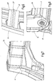
- Fig. 8
- eine Detailansicht einer unteren Ecke der Lehnenstruktur,
- Fig. 9
- eine Explosionsdarstellung des zweiten Ausführungsbeispiels,
- Fig. 10
- eine Seitenansicht des Beschlagoberteils von
Fig. 9 , und - Fig. 11
- einen Schnitt durch einen Holm der Lehnenstruktur.
- Fig. 1
- an exploded view of the first embodiment,
- Fig. 2
- a side view of a vehicle seat,
- Fig. 3
- a perspective view of the backrest structure with fitting,
- Fig. 4
- a front view of the backrest structure with fitting of
Fig. 3 . - Fig. 5
- a side view of the fitting shell of
Fig. 1 . - Fig. 6
- a detailed view of a transverse reinforcement,
- Fig. 7
- a detailed view of an upper corner of the backrest structure,
- Fig. 8
- a detailed view of a lower corner of the backrest structure,
- Fig. 9
- an exploded view of the second embodiment,
- Fig. 10
- a side view of the fitting shell of
Fig. 9 , and - Fig. 11
- a section through a spar of the backrest structure.
Gemäß dem ersten Ausführungsbeispiel weist ein Fahrzeugsitz 1 ein Sitzteil 3 und eine Lehne 5 auf, die relativ zum Sitzteil 3 um eine horizontale, durch zwei Beschläge 7 verlaufende Schwenkachse verschwenkbar ist. Auf der Außenseite eines der Beschläge 7 ist ein Handrad 9 angeordnet, welches der Neigungseinstellung der Lehne 5 dient. Ferner ist für eine Freischwenkfunktion ein Handhebel vorgesehen, der jedoch nicht dargestellt ist.According to the first embodiment, a
Jeder Beschlag 7 umfasst als Herz ein erstes Beschlagteil 11 und ein zweites Beschlagteil 13, welche in baulicher Hinsicht zusammen mit einem Umklammerungsring eine scheibenförmige Einheit bilden, wie sie beispielsweise in der
Am ersten Beschlagteil 11 ist ein erster Adapter 15, und am zweiten Beschlagteil 13 ist ein zweiter Adapter 17 mittels Schweißverbindungen fest angebracht. Über besagten ersten Adapter 15 ist das erste Beschlagteil 11 mit der Struktur (nicht dargestellt) des Sitzteils 3 verbunden, und über besagten zweiten Adapter 17 ist das zweite Beschlagteil 13 mit der Lehnenstruktur 19 verbunden.At the first
Der zweite Adapter 17 ist als Stanz-Biegeteil aus Blech ausgebildet, wobei das Blech eine konstante Blechdicke aufweist. Die Lehnenstruktur 19 ist aus einer Mehrzahl einzelner Stanz-Biegeteile gebildet, wobei die einzelnen Teile miteinander im Wesentlichen zu einem Rahmen verschweißt sind. Auf Grund des - abgesehen vom Handrad 9, welches nur auf einer Seite des Fahrzeugsitzes 1 angeordnet ist - spiegelbildlichen Aufbaus wird im Folgenden nur auf eine Seite der Lehnenstruktur 19 und einen der hieran mittels Schweißverbindungen angebrachten zweiten Adapter 17 samt Beschlag 7 Bezug genommen.The
Die Lehnenstruktur 19 weist im Wesentlichen vier in rechten Winkeln miteinander verbundene, zu offenen Profilen gebogene Bereiche auf, nämlich zwei Seitenwangen 21, einen sitzseitigen Holm 23 und einen kopfstützenseitigen Holm 25. Insbesondere die Seitenwangen 21 und der sitzseitige Holm 23 sind derart C-förmig gebogen oder gerollt, dass die offene Seite nach innen gewandt ist. Ein Beispiel eines derartigen Holms 23, wie im vorliegenden Ausführungsbeispiel verwendet, ist in
Bei den Seitenwangen 21 ist auf der Innenseite ein kleiner Randbereich nach innen gebogen, wobei die beiden Randbereiche miteinander fluchten. Ferner sind in den Seitenwangen 21 mehrere Durchbrüche 21' vorgesehen, welche insbesondere der Material- und Gewichtseinsparung dienen, zudem den Seitenwangen 21 eine definierte Steifigkeit geben. Entlang den außenseitigen Rändern verläuft eine nach außen gebogene Sicke 21" auf einer Seite von unten nach oben und entlang des oberen Endes der Seitenwangen 21 am anderen Rand wieder nach unten.In the case of the
In Längsrichtung etwa in der Mitte der Seitenwangen 21 ist eine Querverbindung 27 zwischen den beiden Seitenwänden an den nach innen gebogenen Randbereichen des C-förmigen Profils angeschweißt. Die Querverbindung 27 ist vorliegend durch ein mit einer abgerundet V-förmigen Sicke 27' (siehe
Im unteren Bereich der Seitenwange 21 ist jeweils der zweite Adapter 17 des entsprechenden Beschlags 7 von außen her angeschweißt, wobei er zwischen sich gegenüberliegenden Sicken 21" angeordnet ist (siehe
Der sitzseitige Holm 23 ist durch ein rechteckförmiges Blech, welches mit einer Mehrzahl von Knicken in Längsrichtung versehen ist, gebildet, wobei es einen annähernd bogenförmigen Verlauf aufweist (siehe
Der kopfstützenseitige Holm 25 ist ebenfalls durch ein Stanz-Biegeteil gebildet, welches mit vorstehenden Bereichen der Seitenwangen 21 verschweißt ist. Im Holm 25 sind u.a. Öffnungen für die Durchführung von Kopfstützenschenkeln vorgesehen. Ferner sind vorliegend quer zur Längsrichtung verlaufende Sicken vorgesehen.The
Gemäß dem zweiten in den
Ferner unterscheidet sich vorliegend die Ausgestaltung des kopfstützenseitigen Holms 25, welcher ebenfalls durch ein Stanz-Biegeteil aus Blech gebildet ist, von dem des ersten Ausfiihrungsbeispiels, wobei im Holm die quer verlaufenden Sicken entfallen und eine in Längsrichtung verlaufende Öffnung vorgesehen ist.Further, in the present case, the configuration of the headrest-
Gemäß einem weiteren, nicht in der Zeichnung dargestellten, dritten Ausführungsbeispiel sind das erste Beschlagteil ohne ersten Adapter direkt mit dem Sitzteil und das zweite Beschlagteil ohne zweiten Adapter direkt mit der Lehnenstruktur verbunden. Ansonsten entspricht die Ausgestaltung derjenigen des ersten Ausführungsbeispiels. Auch in diesem Fall sind die Seitenwangen und Holme profiliert ausgebildet, und ferner sind Querverbindungen an den Seitenwangen vorgesehen, so dass sich der Steifigkeitsverlauf in Bezug auf eine Torsionsbelastung und eine Biegebelastung optimieren lässt, insbesondere lässt sich ein möglichst harmonischer Verlauf der Steifigkeit realisieren. Der Steifigkeitsverlauf weist hierbei bevorzugt keinen Steifigkeitssprung auf, d.h. er ist stetig. Insbesondere bevorzugt ist ein parabelförmiger Steifigkeitsverlauf vorgesehen.According to another, not shown in the drawing, third embodiment, the first fitting part without first adapter directly to the seat part and the second fitting part without a second adapter are connected directly to the backrest structure. Otherwise, the embodiment corresponds to that of the first embodiment. Also in this case, the side cheeks and spars are formed profiled, and further cross connections are provided on the side cheeks, so that the stiffness curve can be optimized with respect to a torsional load and a bending load, in particular a most harmonious course of stiffness can be realized. The stiffness curve in this case preferably has no jump in stiffness, i. he is steady. Particularly preferred is a parabolic stiffness course is provided.
In Abwandlung zum dritten Ausführungsbeispiel ist auch eine Kombination von direkter Anbringung des ersten Beschlagteils am Sitzteil und Anbringung des zweiten Beschlagteils mittels eines Adapters an der Lehnenstruktur oder von Anbringung des ersten Beschlagteils mittels eines Adapters am Sitzteil und direkter Anbringung des zweiten Beschlagteils an der Lehnenstruktur möglich.In a modification of the third embodiment, a combination of direct attachment of the first fitting part on the seat part and attachment of the second fitting part by means of an adapter to the backrest structure or attachment of the first fitting part by means of an adapter on the seat part and direct attachment of the second fitting part on the backrest structure is possible.
- 11
- Fahrzeugsitzvehicle seat
- 33
- Sitzteilseat part
- 55
- Lehnerest
- 77
- Beschlagfitting
- 99
- Handradhandwheel
- 1111
- erstes Beschlagteilfirst fitting part
- 1313
- zweites Beschlagteilsecond fitting part
- 1515
- erster Adapterfirst adapter
- 1717
- zweiter Adaptersecond adapter
- 17'17 '
- erster Durchbruchfirst breakthrough
- 17"17 "
- zweiter Durchbruchsecond breakthrough
- 17"'17 " '
- Randedge
- 17""17 ""
- Ausschnittneckline
- 1919
- Lehnenstrukturback structure
- 2121
- Seitenwangeside cheek
- 21'21 '
- Durchbruchbreakthrough
- 21"21 "
- Sicke (Seitenwange)Beading (sidewall)
- 2323
- sitzseitiger Holmseat-side spar
- 2525
- kopfstützenseitiger Holmheadrest side spar
- 2727
- Querverbindungcross connection
- 27'27 '
- Sicke (Querverbindung)Beading (cross connection)
- 27"27 "
- flügelartiger Randbereichwing-like edge area
Claims (11)
- A vehicle seat, in particular for a motor vehicle seat, comprising fixtures (7), having a first fixture part (11) and a second fixture part (13), and a backrest structure (19) having lateral cheeks (21) and at least one bar (23, 25) connecting the lateral cheeks (21),
the first fixture part (11) being fixedly connected to a seat part (3) of the vehicle seat (1), in particular by means of an adapter (15) and the second fixture part (13) being able to be rotated for adjusting the inclination of a backrest (3) of the vehicle seat (1) between a plurality of positions of use relative to the first fixture part (11) and the backrest structure (19) being fixedly connected to the second fixture part (13), in particular via a second adapter (17), and wherein the lateral cheeks (21) of the backrest structure (19) are formed by open profiles, the open profile being closed in a central region of the lateral cheeks (21) by at least one crossbar (27) which is fixedly connected to the lateral cheeks (21),
wherein the lateral cheeks (21) in their longitudinal direction on both sides have an edge region bent back twice by 90° as well as at least one through-hole (21') in the central region along the central longitudinal line, and characterized in that
the crossbar (27) is a stamped-bent part made of sheet metal, which comprises at least one bead (27') extending in the longitudinal direction of the part and two wing-like regions (27") extending outwardly to the side of the bead (27'). - The vehicle seat according to claim 1, characterized in that the lateral cheeks (21) comprise two beads (21") extending parallel to the edge region, which extend outwardly away from the crossbar (27).
- The vehicle seat according to claim 1, characterized in that the bead (27') of the crossbar (27) is arranged in the center perpendicular to and/or relative to at least one of the front and rear side surfaces of the lateral cheeks (21).
- The vehicle seat according to one of the preceding claims, characterized in that the lateral cheeks (21) at the end on the headrest side are connected to one another via a bar (25) on the headrest side, the bar (25) being formed by a stamped-bent part.
- The vehicle seat according to one of the preceding claims, characterized in that the lateral cheeks (21) at the end on the seat side are connected to one another via a bar (23) on the seat side, the bar (23) being formed by a rolled and formed part.
- The vehicle seat according to one of the preceding claims, characterized in that the lateral cheeks (21) are connected to the fixtures (7) via an adapter (17), the adapter (17) having a circular through-hole (17') and a bent-back edge (17"') along both longitudinal sides.
- The vehicle seat according to claim 6, characterized in that the adapter (17) has a second through-hole (17") or a cutout (17"") which is configured to extend between the bent-back edges (17"').
- The vehicle seat according to claim 7, characterized in that the second through-hole (17") is of approximately rectangular configuration.
- The vehicle seat according to one of the preceding claims, characterized in that the stiffness distribution is constant.
- The vehicle seat according to claim 9, characterized in that the stiffness distribution is parabolic.
- The vehicle seat according to one of the preceding claims, characterized in that the lateral cheeks (21) of the backrest structure (19) are formed by C-shaped profiles which are open in the direction of the central plane of the vehicle seat, the crossbar (27) connecting the free end regions of the limbs of the respective C-shaped profile in the central region of the lateral cheeks (21).
Priority Applications (1)
| Application Number | Priority Date | Filing Date | Title |
|---|---|---|---|
| PL09745498T PL2276648T3 (en) | 2008-05-13 | 2009-04-28 | Vehicle seat comprising fixtures |
Applications Claiming Priority (2)
| Application Number | Priority Date | Filing Date | Title |
|---|---|---|---|
| DE102008023943A DE102008023943B4 (en) | 2008-05-13 | 2008-05-13 | Vehicle seat with fittings |
| PCT/EP2009/003058 WO2009138164A2 (en) | 2008-05-13 | 2009-04-28 | Vehicle seat comprising fixtures |
Publications (2)
| Publication Number | Publication Date |
|---|---|
| EP2276648A2 EP2276648A2 (en) | 2011-01-26 |
| EP2276648B1 true EP2276648B1 (en) | 2014-03-12 |
Family
ID=40792473
Family Applications (1)
| Application Number | Title | Priority Date | Filing Date |
|---|---|---|---|
| EP09745498.7A Not-in-force EP2276648B1 (en) | 2008-05-13 | 2009-04-28 | Vehicle seat comprising fixtures |
Country Status (7)
| Country | Link |
|---|---|
| US (1) | US8550563B2 (en) |
| EP (1) | EP2276648B1 (en) |
| CN (1) | CN102026844A (en) |
| BR (1) | BRPI0912515A2 (en) |
| DE (1) | DE102008023943B4 (en) |
| PL (1) | PL2276648T3 (en) |
| WO (1) | WO2009138164A2 (en) |
Families Citing this family (15)
| Publication number | Priority date | Publication date | Assignee | Title |
|---|---|---|---|---|
| JP5563667B2 (en) * | 2009-11-12 | 2014-07-30 | ジョンソン コントロールズ テクノロジー カンパニー | One-piece type seat back frame assembly and manufacturing method thereof |
| DE102011102420B4 (en) * | 2011-05-24 | 2021-05-06 | Adient Luxembourg Holding S.À R.L. | Vehicle seat, in particular vehicle seat |
| DE202011105603U1 (en) | 2011-09-10 | 2011-10-24 | Keiper Gmbh & Co. Kg | Backrest structure for a vehicle seat |
| EP2807052B8 (en) * | 2012-01-26 | 2017-08-30 | Johnson Controls Technology Company | Method for manufacturing a one-piece seat back structure |
| JP2013244872A (en) * | 2012-05-28 | 2013-12-09 | Toyota Boshoku Corp | Seat back frame structure for vehicle seat |
| DE102013003787B4 (en) * | 2012-11-30 | 2022-09-08 | Adient Us Llc | vehicle seat |
| CN104870253B (en) * | 2012-12-28 | 2018-05-15 | 提爱思科技股份有限公司 | Seat unit |
| JP6215634B2 (en) * | 2013-09-30 | 2017-10-18 | トヨタ紡織株式会社 | Vehicle seat frame |
| JP6218324B2 (en) | 2014-01-29 | 2017-10-25 | 株式会社タチエス | Seat frame forming method for vehicle seat, seat frame and vehicle seat |
| CN104097005B (en) * | 2014-07-04 | 2015-11-25 | 重庆格一机械制造有限公司 | The weld jig of automobile rear seat cushion steel-wire carcass |
| JP6617063B2 (en) * | 2016-03-16 | 2019-12-04 | 株式会社タチエス | Vehicle seat |
| DE102016115266B4 (en) * | 2016-08-17 | 2021-05-12 | Grammer Aktiengesellschaft | Device with adapter element and method for connecting |
| JP6783621B2 (en) * | 2016-10-26 | 2020-11-11 | 株式会社タチエス | Vehicle seat |
| CN112711817B (en) * | 2019-10-24 | 2023-04-28 | 深圳市建筑设计研究总院有限公司 | Support connecting method for flexural member |
| US11440452B2 (en) * | 2020-10-27 | 2022-09-13 | Ford Global Technologies, Llc | Composite seat back |
Citations (2)
| Publication number | Priority date | Publication date | Assignee | Title |
|---|---|---|---|---|
| FR2753935A1 (en) * | 1996-10-02 | 1998-04-03 | Faure Bertrand Equipements Sa | Vehicle seat manufacture |
| WO2006055616A1 (en) * | 2004-11-18 | 2006-05-26 | Johnson Controls Technology Company | Seat frame system and method of manufacturing |
Family Cites Families (31)
| Publication number | Priority date | Publication date | Assignee | Title |
|---|---|---|---|---|
| US2136122A (en) * | 1935-03-21 | 1938-11-08 | Midland Steel Prod Co | Chassis side rail |
| DE3239292A1 (en) * | 1981-11-11 | 1983-05-19 | Keiper Automobiltechnik Gmbh & Co Kg, 5630 Remscheid | Backrest frame for seats, in particular for motor vehicle seats |
| JPS6036797U (en) * | 1983-08-19 | 1985-03-13 | 株式会社タチエス | Vehicle seat with thigh support device |
| DE3706394C1 (en) * | 1987-02-27 | 1988-05-11 | Audi Ag | Backrest for vehicle front seats |
| JPH0753556Y2 (en) * | 1990-11-26 | 1995-12-13 | 池田物産株式会社 | Back frame |
| DE4436101C5 (en) | 1993-11-30 | 2008-12-11 | Keiper Gmbh & Co.Kg | Lehneneinstellbeschlag for seats with adjustable backrest, in particular motor vehicle seats |
| US5547259A (en) * | 1994-05-09 | 1996-08-20 | Mitchell Corporation Of Owosso, Inc. | Modular automotive seat frame |
| DE19500914A1 (en) * | 1995-01-13 | 1996-07-18 | Hammerstein Gmbh C Rob | Hinge joint for vehicle seat adjustable backrest with cam-locked gears |
| DE19603946C2 (en) * | 1996-02-05 | 1998-06-04 | Daimler Benz Ag | Vehicle seat |
| US6233826B1 (en) * | 1997-07-21 | 2001-05-22 | Henkel Corp | Method for reinforcing structural members |
| JP3376887B2 (en) * | 1997-10-13 | 2003-02-10 | トヨタ自動車株式会社 | Vehicle seat |
| DE19826732B4 (en) * | 1998-06-16 | 2007-03-29 | Euromotive Ges.M.B.H. | Seatback design |
| DE19904300C1 (en) | 1999-01-28 | 2000-08-03 | Keiper Gmbh & Co | Ratchet fitting for a vehicle seat has a guide for the bolt which also acts as the mounting for the upper and lower sections with a toothed segment at the bolt engaging a rim gear at the limit surface |
| JP2000333768A (en) * | 1999-05-31 | 2000-12-05 | Ikeda Bussan Co Ltd | Seat back frame |
| DE29910063U1 (en) * | 1999-06-09 | 2000-10-12 | Johnson Controls Gmbh | Rail element for power support in a vehicle |
| US6149235A (en) * | 1999-08-13 | 2000-11-21 | Lear Corporation | Rotary-cam type reclining device |
| JP2001149176A (en) * | 1999-11-29 | 2001-06-05 | Tachi S Co Ltd | Seat back frame structure |
| JP4348808B2 (en) * | 1999-12-27 | 2009-10-21 | トヨタ紡織株式会社 | Mounting structure of functional members to the frame |
| DE10105282B4 (en) | 2001-02-06 | 2005-03-24 | Keiper Gmbh & Co. Kg | Fitting for a vehicle seat |
| US6767055B1 (en) * | 2002-03-11 | 2004-07-27 | Bostrom Seating, Inc. | Vehicle seat frame and belt assembly |
| DE10219199A1 (en) * | 2002-04-29 | 2003-11-06 | Hammerstein Gmbh C Rob | Backrest joint fitting for a motor vehicle seat |
| US20040113481A1 (en) * | 2002-09-13 | 2004-06-17 | Mohammad Saberan | Vehicle seat frame |
| US6857698B2 (en) * | 2003-02-21 | 2005-02-22 | Lear Corporation | Seat side impact resistance mechanism |
| JP2005186670A (en) * | 2003-12-24 | 2005-07-14 | Delta Kogyo Co Ltd | Vehicle seat |
| US7255400B2 (en) * | 2004-02-23 | 2007-08-14 | Intier Automotive Inc. | Tubeless headrest support system |
| JP4916155B2 (en) * | 2004-12-28 | 2012-04-11 | デルタ工業株式会社 | Reclining device |
| JP4704116B2 (en) * | 2005-06-07 | 2011-06-15 | 難波プレス工業株式会社 | seat |
| JP2007111340A (en) | 2005-10-21 | 2007-05-10 | Inagaki:Kk | Chair with back load receptacle |
| JP4643480B2 (en) * | 2006-03-23 | 2011-03-02 | トヨタ自動車株式会社 | Vehicle seat back frame |
| DE102006036935A1 (en) * | 2006-08-08 | 2007-10-31 | Twb-Presswerk Gmbh & Co. Kg | Automotive rear bench backrest is assembled from standard panels welded at overlap zones |
| DE102007016690A1 (en) * | 2006-10-27 | 2008-04-30 | Johnson Controls Gmbh | Motor vehicle seat has structural element with number of components, which are connected to each other, and component is available as steel and light weight design |
-
2008
- 2008-05-13 DE DE102008023943A patent/DE102008023943B4/en not_active Expired - Fee Related
-
2009
- 2009-04-28 EP EP09745498.7A patent/EP2276648B1/en not_active Not-in-force
- 2009-04-28 CN CN2009801170863A patent/CN102026844A/en active Pending
- 2009-04-28 US US12/863,079 patent/US8550563B2/en not_active Expired - Fee Related
- 2009-04-28 WO PCT/EP2009/003058 patent/WO2009138164A2/en active Application Filing
- 2009-04-28 PL PL09745498T patent/PL2276648T3/en unknown
- 2009-04-28 BR BRPI0912515A patent/BRPI0912515A2/en not_active IP Right Cessation
Patent Citations (2)
| Publication number | Priority date | Publication date | Assignee | Title |
|---|---|---|---|---|
| FR2753935A1 (en) * | 1996-10-02 | 1998-04-03 | Faure Bertrand Equipements Sa | Vehicle seat manufacture |
| WO2006055616A1 (en) * | 2004-11-18 | 2006-05-26 | Johnson Controls Technology Company | Seat frame system and method of manufacturing |
Also Published As
| Publication number | Publication date |
|---|---|
| EP2276648A2 (en) | 2011-01-26 |
| WO2009138164A2 (en) | 2009-11-19 |
| DE102008023943B4 (en) | 2012-03-15 |
| US20110043022A1 (en) | 2011-02-24 |
| BRPI0912515A2 (en) | 2019-09-24 |
| WO2009138164A3 (en) | 2010-05-06 |
| PL2276648T3 (en) | 2014-08-29 |
| CN102026844A (en) | 2011-04-20 |
| US8550563B2 (en) | 2013-10-08 |
| DE102008023943A1 (en) | 2009-11-19 |
Similar Documents
| Publication | Publication Date | Title |
|---|---|---|
| EP2276648B1 (en) | Vehicle seat comprising fixtures | |
| EP2057032B1 (en) | Vehicle seat, in particular commercial vehicle seat | |
| EP2925562B1 (en) | Vehicle seat | |
| EP1654150B1 (en) | Junction structure for connecting two profiles in a vehicle support frame | |
| EP2376309B1 (en) | Vehicle seat, in particular motor vehicle seat | |
| DE102013204249A1 (en) | vehicle seat | |
| EP2830910B1 (en) | Vehicle seat | |
| DE112015000063B4 (en) | Vehicle body having an opening in a vehicle body rear portion | |
| WO2013110528A1 (en) | Subframe for a motor vehicle | |
| DE102007007296A1 (en) | Vehicle seat, in particular motor vehicle seat | |
| DE102010006669A1 (en) | Profile node for car body, has strengthening element connected with cast node parts, where cross beam made from steel material is attached at cast node parts and runs crosswise relative to longitudinal beam path | |
| DE112012004351B4 (en) | Seat with welded cross shaft | |
| EP3539818B1 (en) | Belt frame for a vehicle seat or a bench seat and vehicle seating assembly | |
| EP2630007A1 (en) | Vehicle seat, in particular a motor vehicle seat | |
| DE202008002339U1 (en) | Vehicle seat, in particular commercial vehicle seat | |
| EP2838759B1 (en) | Support structure for an armrest of a vehicle | |
| DE202014103332U1 (en) | Floor assembly for vehicles and vehicles with such a floor assembly | |
| WO2014131529A1 (en) | Backrest frame for a seat, in particular for a vehicle seat, and vehicle seat | |
| DE19905295B4 (en) | Mounting structure for a vehicle seat backrest | |
| DE102010021744A1 (en) | Method for mounting vehicle seat, involves providing seat cushion and backrest of vehicle seat with structure components, where longitudinal bar is fitted for backrest to begin with backrest adjuster, in order to create seat side part | |
| DE102006018289A1 (en) | Backrest framework for motor vehicle`s rear seat, has auxiliary profile parts, where parts connect carriers that meet at frame joint, with each other and with adjacent additional components by form-fit connection | |
| DE102016117886A1 (en) | Device for arranging a passenger restraint system in a means of transport, person seat arrangement and means of transport | |
| EP3238987B1 (en) | Device for arranging a passenger retention system in a means of transport, passenger seat assembly and means of transport | |
| DE202011105603U1 (en) | Backrest structure for a vehicle seat | |
| DE102021123829A1 (en) | Seat assembly base, vehicle floor structure and vehicle |
Legal Events
| Date | Code | Title | Description |
|---|---|---|---|
| PUAI | Public reference made under article 153(3) epc to a published international application that has entered the european phase |
Free format text: ORIGINAL CODE: 0009012 |
|
| 17P | Request for examination filed |
Effective date: 20100928 |
|
| AK | Designated contracting states |
Kind code of ref document: A2 Designated state(s): AT BE BG CH CY CZ DE DK EE ES FI FR GB GR HR HU IE IS IT LI LT LU LV MC MK MT NL NO PL PT RO SE SI SK TR |
|
| DAX | Request for extension of the european patent (deleted) | ||
| 17Q | First examination report despatched |
Effective date: 20130208 |
|
| GRAP | Despatch of communication of intention to grant a patent |
Free format text: ORIGINAL CODE: EPIDOSNIGR1 |
|
| INTG | Intention to grant announced |
Effective date: 20131023 |
|
| GRAS | Grant fee paid |
Free format text: ORIGINAL CODE: EPIDOSNIGR3 |
|
| GRAA | (expected) grant |
Free format text: ORIGINAL CODE: 0009210 |
|
| AK | Designated contracting states |
Kind code of ref document: B1 Designated state(s): AT BE BG CH CY CZ DE DK EE ES FI FR GB GR HR HU IE IS IT LI LT LU LV MC MK MT NL NO PL PT RO SE SI SK TR |
|
| REG | Reference to a national code |
Ref country code: GB Ref legal event code: FG4D Free format text: NOT ENGLISH |
|
| REG | Reference to a national code |
Ref country code: CH Ref legal event code: EP |
|
| REG | Reference to a national code |
Ref country code: AT Ref legal event code: REF Ref document number: 656041 Country of ref document: AT Kind code of ref document: T Effective date: 20140315 |
|
| REG | Reference to a national code |
Ref country code: IE Ref legal event code: FG4D Free format text: LANGUAGE OF EP DOCUMENT: GERMAN |
|
| REG | Reference to a national code |
Ref country code: DE Ref legal event code: R096 Ref document number: 502009008982 Country of ref document: DE Effective date: 20140424 |
|
| REG | Reference to a national code |
Ref country code: NL Ref legal event code: VDEP Effective date: 20140312 |
|
| PG25 | Lapsed in a contracting state [announced via postgrant information from national office to epo] |
Ref country code: LT Free format text: LAPSE BECAUSE OF FAILURE TO SUBMIT A TRANSLATION OF THE DESCRIPTION OR TO PAY THE FEE WITHIN THE PRESCRIBED TIME-LIMIT Effective date: 20140312 Ref country code: NO Free format text: LAPSE BECAUSE OF FAILURE TO SUBMIT A TRANSLATION OF THE DESCRIPTION OR TO PAY THE FEE WITHIN THE PRESCRIBED TIME-LIMIT Effective date: 20140612 |
|
| REG | Reference to a national code |
Ref country code: SK Ref legal event code: T3 Ref document number: E 16263 Country of ref document: SK |
|
| REG | Reference to a national code |
Ref country code: DE Ref legal event code: R081 Ref document number: 502009008982 Country of ref document: DE Owner name: JOHNSON CONTROLS COMPONENTS GMBH & CO. KG, DE Free format text: FORMER OWNER: KEIPER GMBH & CO. KG, 67657 KAISERSLAUTERN, DE Effective date: 20140710 Ref country code: DE Ref legal event code: R081 Ref document number: 502009008982 Country of ref document: DE Owner name: ADIENT LUXEMBOURG HOLDING S.A.R.L., LU Free format text: FORMER OWNER: KEIPER GMBH & CO. KG, 67657 KAISERSLAUTERN, DE Effective date: 20140710 Ref country code: DE Ref legal event code: R081 Ref document number: 502009008982 Country of ref document: DE Owner name: ADIENT LUXEMBOURG HOLDING S.A R.L., LU Free format text: FORMER OWNER: KEIPER GMBH & CO. KG, 67657 KAISERSLAUTERN, DE Effective date: 20140710 |
|
| REG | Reference to a national code |
Ref country code: LT Ref legal event code: MG4D |
|
| PG25 | Lapsed in a contracting state [announced via postgrant information from national office to epo] |
Ref country code: CY Free format text: LAPSE BECAUSE OF FAILURE TO SUBMIT A TRANSLATION OF THE DESCRIPTION OR TO PAY THE FEE WITHIN THE PRESCRIBED TIME-LIMIT Effective date: 20140312 Ref country code: SE Free format text: LAPSE BECAUSE OF FAILURE TO SUBMIT A TRANSLATION OF THE DESCRIPTION OR TO PAY THE FEE WITHIN THE PRESCRIBED TIME-LIMIT Effective date: 20140312 Ref country code: FI Free format text: LAPSE BECAUSE OF FAILURE TO SUBMIT A TRANSLATION OF THE DESCRIPTION OR TO PAY THE FEE WITHIN THE PRESCRIBED TIME-LIMIT Effective date: 20140312 |
|
| REG | Reference to a national code |
Ref country code: PL Ref legal event code: T3 |
|
| RAP2 | Party data changed (patent owner data changed or rights of a patent transferred) |
Owner name: JOHNSON CONTROLS COMPONENTS GMBH & CO. KG |
|
| PG25 | Lapsed in a contracting state [announced via postgrant information from national office to epo] |
Ref country code: HR Free format text: LAPSE BECAUSE OF FAILURE TO SUBMIT A TRANSLATION OF THE DESCRIPTION OR TO PAY THE FEE WITHIN THE PRESCRIBED TIME-LIMIT Effective date: 20140312 Ref country code: LV Free format text: LAPSE BECAUSE OF FAILURE TO SUBMIT A TRANSLATION OF THE DESCRIPTION OR TO PAY THE FEE WITHIN THE PRESCRIBED TIME-LIMIT Effective date: 20140312 |
|
| PG25 | Lapsed in a contracting state [announced via postgrant information from national office to epo] |
Ref country code: RO Free format text: LAPSE BECAUSE OF FAILURE TO SUBMIT A TRANSLATION OF THE DESCRIPTION OR TO PAY THE FEE WITHIN THE PRESCRIBED TIME-LIMIT Effective date: 20140312 Ref country code: NL Free format text: LAPSE BECAUSE OF FAILURE TO SUBMIT A TRANSLATION OF THE DESCRIPTION OR TO PAY THE FEE WITHIN THE PRESCRIBED TIME-LIMIT Effective date: 20140312 Ref country code: IS Free format text: LAPSE BECAUSE OF FAILURE TO SUBMIT A TRANSLATION OF THE DESCRIPTION OR TO PAY THE FEE WITHIN THE PRESCRIBED TIME-LIMIT Effective date: 20140712 Ref country code: BG Free format text: LAPSE BECAUSE OF FAILURE TO SUBMIT A TRANSLATION OF THE DESCRIPTION OR TO PAY THE FEE WITHIN THE PRESCRIBED TIME-LIMIT Effective date: 20140612 Ref country code: EE Free format text: LAPSE BECAUSE OF FAILURE TO SUBMIT A TRANSLATION OF THE DESCRIPTION OR TO PAY THE FEE WITHIN THE PRESCRIBED TIME-LIMIT Effective date: 20140312 |
|
| PG25 | Lapsed in a contracting state [announced via postgrant information from national office to epo] |
Ref country code: ES Free format text: LAPSE BECAUSE OF FAILURE TO SUBMIT A TRANSLATION OF THE DESCRIPTION OR TO PAY THE FEE WITHIN THE PRESCRIBED TIME-LIMIT Effective date: 20140312 Ref country code: MC Free format text: LAPSE BECAUSE OF FAILURE TO SUBMIT A TRANSLATION OF THE DESCRIPTION OR TO PAY THE FEE WITHIN THE PRESCRIBED TIME-LIMIT Effective date: 20140312 |
|
| REG | Reference to a national code |
Ref country code: CH Ref legal event code: PL |
|
| REG | Reference to a national code |
Ref country code: DE Ref legal event code: R097 Ref document number: 502009008982 Country of ref document: DE |
|
| PG25 | Lapsed in a contracting state [announced via postgrant information from national office to epo] |
Ref country code: PT Free format text: LAPSE BECAUSE OF FAILURE TO SUBMIT A TRANSLATION OF THE DESCRIPTION OR TO PAY THE FEE WITHIN THE PRESCRIBED TIME-LIMIT Effective date: 20140714 |
|
| PLBE | No opposition filed within time limit |
Free format text: ORIGINAL CODE: 0009261 |
|
| STAA | Information on the status of an ep patent application or granted ep patent |
Free format text: STATUS: NO OPPOSITION FILED WITHIN TIME LIMIT |
|
| REG | Reference to a national code |
Ref country code: IE Ref legal event code: MM4A |
|
| PG25 | Lapsed in a contracting state [announced via postgrant information from national office to epo] |
Ref country code: DK Free format text: LAPSE BECAUSE OF FAILURE TO SUBMIT A TRANSLATION OF THE DESCRIPTION OR TO PAY THE FEE WITHIN THE PRESCRIBED TIME-LIMIT Effective date: 20140312 Ref country code: CH Free format text: LAPSE BECAUSE OF NON-PAYMENT OF DUE FEES Effective date: 20140430 Ref country code: LI Free format text: LAPSE BECAUSE OF NON-PAYMENT OF DUE FEES Effective date: 20140430 |
|
| 26N | No opposition filed |
Effective date: 20141215 |
|
| GBPC | Gb: european patent ceased through non-payment of renewal fee |
Effective date: 20140612 |
|
| REG | Reference to a national code |
Ref country code: DE Ref legal event code: R097 Ref document number: 502009008982 Country of ref document: DE Effective date: 20141215 |
|
| PG25 | Lapsed in a contracting state [announced via postgrant information from national office to epo] |
Ref country code: IT Free format text: LAPSE BECAUSE OF FAILURE TO SUBMIT A TRANSLATION OF THE DESCRIPTION OR TO PAY THE FEE WITHIN THE PRESCRIBED TIME-LIMIT Effective date: 20140312 |
|
| PG25 | Lapsed in a contracting state [announced via postgrant information from national office to epo] |
Ref country code: IE Free format text: LAPSE BECAUSE OF NON-PAYMENT OF DUE FEES Effective date: 20140428 |
|
| PG25 | Lapsed in a contracting state [announced via postgrant information from national office to epo] |
Ref country code: GB Free format text: LAPSE BECAUSE OF NON-PAYMENT OF DUE FEES Effective date: 20140612 |
|
| REG | Reference to a national code |
Ref country code: AT Ref legal event code: MM01 Ref document number: 656041 Country of ref document: AT Kind code of ref document: T Effective date: 20140428 |
|
| PG25 | Lapsed in a contracting state [announced via postgrant information from national office to epo] |
Ref country code: SI Free format text: LAPSE BECAUSE OF FAILURE TO SUBMIT A TRANSLATION OF THE DESCRIPTION OR TO PAY THE FEE WITHIN THE PRESCRIBED TIME-LIMIT Effective date: 20140312 |
|
| PG25 | Lapsed in a contracting state [announced via postgrant information from national office to epo] |
Ref country code: AT Free format text: LAPSE BECAUSE OF NON-PAYMENT OF DUE FEES Effective date: 20140428 |
|
| PG25 | Lapsed in a contracting state [announced via postgrant information from national office to epo] |
Ref country code: MT Free format text: LAPSE BECAUSE OF FAILURE TO SUBMIT A TRANSLATION OF THE DESCRIPTION OR TO PAY THE FEE WITHIN THE PRESCRIBED TIME-LIMIT Effective date: 20140312 |
|
| REG | Reference to a national code |
Ref country code: FR Ref legal event code: PLFP Year of fee payment: 8 |
|
| PG25 | Lapsed in a contracting state [announced via postgrant information from national office to epo] |
Ref country code: GR Free format text: LAPSE BECAUSE OF FAILURE TO SUBMIT A TRANSLATION OF THE DESCRIPTION OR TO PAY THE FEE WITHIN THE PRESCRIBED TIME-LIMIT Effective date: 20140613 |
|
| PG25 | Lapsed in a contracting state [announced via postgrant information from national office to epo] |
Ref country code: TR Free format text: LAPSE BECAUSE OF FAILURE TO SUBMIT A TRANSLATION OF THE DESCRIPTION OR TO PAY THE FEE WITHIN THE PRESCRIBED TIME-LIMIT Effective date: 20140312 Ref country code: HU Free format text: LAPSE BECAUSE OF FAILURE TO SUBMIT A TRANSLATION OF THE DESCRIPTION OR TO PAY THE FEE WITHIN THE PRESCRIBED TIME-LIMIT; INVALID AB INITIO Effective date: 20090428 Ref country code: BE Free format text: LAPSE BECAUSE OF FAILURE TO SUBMIT A TRANSLATION OF THE DESCRIPTION OR TO PAY THE FEE WITHIN THE PRESCRIBED TIME-LIMIT Effective date: 20140430 Ref country code: LU Free format text: LAPSE BECAUSE OF NON-PAYMENT OF DUE FEES Effective date: 20140428 |
|
| REG | Reference to a national code |
Ref country code: DE Ref legal event code: R081 Ref document number: 502009008982 Country of ref document: DE Owner name: ADIENT LUXEMBOURG HOLDING S.A.R.L., LU Free format text: FORMER OWNER: JOHNSON CONTROLS COMPONENTS GMBH & CO. KG, 67657 KAISERSLAUTERN, DE Ref country code: DE Ref legal event code: R081 Ref document number: 502009008982 Country of ref document: DE Owner name: ADIENT LUXEMBOURG HOLDING S.A R.L., LU Free format text: FORMER OWNER: JOHNSON CONTROLS COMPONENTS GMBH & CO. KG, 67657 KAISERSLAUTERN, DE |
|
| REG | Reference to a national code |
Ref country code: FR Ref legal event code: PLFP Year of fee payment: 9 |
|
| PGFP | Annual fee paid to national office [announced via postgrant information from national office to epo] |
Ref country code: CZ Payment date: 20170324 Year of fee payment: 9 |
|
| PGFP | Annual fee paid to national office [announced via postgrant information from national office to epo] |
Ref country code: SK Payment date: 20170425 Year of fee payment: 9 |
|
| PGFP | Annual fee paid to national office [announced via postgrant information from national office to epo] |
Ref country code: PL Payment date: 20170425 Year of fee payment: 9 |
|
| REG | Reference to a national code |
Ref country code: DE Ref legal event code: R081 Ref document number: 502009008982 Country of ref document: DE Owner name: ADIENT LUXEMBOURG HOLDING S.A R.L., LU Free format text: FORMER OWNER: ADIENT LUXEMBOURG HOLDING S.A.R.L., LUXEMBOURG, LU |
|
| REG | Reference to a national code |
Ref country code: FR Ref legal event code: PLFP Year of fee payment: 10 |
|
| PG25 | Lapsed in a contracting state [announced via postgrant information from national office to epo] |
Ref country code: MK Free format text: LAPSE BECAUSE OF FAILURE TO SUBMIT A TRANSLATION OF THE DESCRIPTION OR TO PAY THE FEE WITHIN THE PRESCRIBED TIME-LIMIT Effective date: 20140312 |
|
| PGFP | Annual fee paid to national office [announced via postgrant information from national office to epo] |
Ref country code: DE Payment date: 20180430 Year of fee payment: 10 |
|
| REG | Reference to a national code |
Ref country code: SK Ref legal event code: MM4A Ref document number: E 16263 Country of ref document: SK Effective date: 20180428 |
|
| PG25 | Lapsed in a contracting state [announced via postgrant information from national office to epo] |
Ref country code: SK Free format text: LAPSE BECAUSE OF NON-PAYMENT OF DUE FEES Effective date: 20180428 Ref country code: CZ Free format text: LAPSE BECAUSE OF NON-PAYMENT OF DUE FEES Effective date: 20180428 |
|
| PGFP | Annual fee paid to national office [announced via postgrant information from national office to epo] |
Ref country code: FR Payment date: 20190418 Year of fee payment: 11 |
|
| REG | Reference to a national code |
Ref country code: DE Ref legal event code: R119 Ref document number: 502009008982 Country of ref document: DE |
|
| PG25 | Lapsed in a contracting state [announced via postgrant information from national office to epo] |
Ref country code: PL Free format text: LAPSE BECAUSE OF NON-PAYMENT OF DUE FEES Effective date: 20180428 |
|
| PG25 | Lapsed in a contracting state [announced via postgrant information from national office to epo] |
Ref country code: DE Free format text: LAPSE BECAUSE OF NON-PAYMENT OF DUE FEES Effective date: 20191101 |
|
| PG25 | Lapsed in a contracting state [announced via postgrant information from national office to epo] |
Ref country code: FR Free format text: LAPSE BECAUSE OF NON-PAYMENT OF DUE FEES Effective date: 20200430 |