EP2276143B1 - Appareil d'alimentation électrique et procédé de contrôle d'alimentation électrique - Google Patents
Appareil d'alimentation électrique et procédé de contrôle d'alimentation électrique Download PDFInfo
- Publication number
- EP2276143B1 EP2276143B1 EP10169260.6A EP10169260A EP2276143B1 EP 2276143 B1 EP2276143 B1 EP 2276143B1 EP 10169260 A EP10169260 A EP 10169260A EP 2276143 B1 EP2276143 B1 EP 2276143B1
- Authority
- EP
- European Patent Office
- Prior art keywords
- power supply
- voltage
- circuit
- output
- backup
- Prior art date
- Legal status (The legal status is an assumption and is not a legal conclusion. Google has not performed a legal analysis and makes no representation as to the accuracy of the status listed.)
- Not-in-force
Links
Images


Classifications
-
- H—ELECTRICITY
- H02—GENERATION; CONVERSION OR DISTRIBUTION OF ELECTRIC POWER
- H02J—CIRCUIT ARRANGEMENTS OR SYSTEMS FOR SUPPLYING OR DISTRIBUTING ELECTRIC POWER; SYSTEMS FOR STORING ELECTRIC ENERGY
- H02J9/00—Circuit arrangements for emergency or stand-by power supply, e.g. for emergency lighting
- H02J9/04—Circuit arrangements for emergency or stand-by power supply, e.g. for emergency lighting in which the distribution system is disconnected from the normal source and connected to a standby source
- H02J9/06—Circuit arrangements for emergency or stand-by power supply, e.g. for emergency lighting in which the distribution system is disconnected from the normal source and connected to a standby source with automatic change-over, e.g. UPS systems
- H02J9/061—Circuit arrangements for emergency or stand-by power supply, e.g. for emergency lighting in which the distribution system is disconnected from the normal source and connected to a standby source with automatic change-over, e.g. UPS systems for DC powered loads
-
- H—ELECTRICITY
- H02—GENERATION; CONVERSION OR DISTRIBUTION OF ELECTRIC POWER
- H02J—CIRCUIT ARRANGEMENTS OR SYSTEMS FOR SUPPLYING OR DISTRIBUTING ELECTRIC POWER; SYSTEMS FOR STORING ELECTRIC ENERGY
- H02J9/00—Circuit arrangements for emergency or stand-by power supply, e.g. for emergency lighting
- H02J9/005—Circuit arrangements for emergency or stand-by power supply, e.g. for emergency lighting using a power saving mode
-
- Y—GENERAL TAGGING OF NEW TECHNOLOGICAL DEVELOPMENTS; GENERAL TAGGING OF CROSS-SECTIONAL TECHNOLOGIES SPANNING OVER SEVERAL SECTIONS OF THE IPC; TECHNICAL SUBJECTS COVERED BY FORMER USPC CROSS-REFERENCE ART COLLECTIONS [XRACs] AND DIGESTS
- Y02—TECHNOLOGIES OR APPLICATIONS FOR MITIGATION OR ADAPTATION AGAINST CLIMATE CHANGE
- Y02B—CLIMATE CHANGE MITIGATION TECHNOLOGIES RELATED TO BUILDINGS, e.g. HOUSING, HOUSE APPLIANCES OR RELATED END-USER APPLICATIONS
- Y02B70/00—Technologies for an efficient end-user side electric power management and consumption
- Y02B70/30—Systems integrating technologies related to power network operation and communication or information technologies for improving the carbon footprint of the management of residential or tertiary loads, i.e. smart grids as climate change mitigation technology in the buildings sector, including also the last stages of power distribution and the control, monitoring or operating management systems at local level
-
- Y—GENERAL TAGGING OF NEW TECHNOLOGICAL DEVELOPMENTS; GENERAL TAGGING OF CROSS-SECTIONAL TECHNOLOGIES SPANNING OVER SEVERAL SECTIONS OF THE IPC; TECHNICAL SUBJECTS COVERED BY FORMER USPC CROSS-REFERENCE ART COLLECTIONS [XRACs] AND DIGESTS
- Y04—INFORMATION OR COMMUNICATION TECHNOLOGIES HAVING AN IMPACT ON OTHER TECHNOLOGY AREAS
- Y04S—SYSTEMS INTEGRATING TECHNOLOGIES RELATED TO POWER NETWORK OPERATION, COMMUNICATION OR INFORMATION TECHNOLOGIES FOR IMPROVING THE ELECTRICAL POWER GENERATION, TRANSMISSION, DISTRIBUTION, MANAGEMENT OR USAGE, i.e. SMART GRIDS
- Y04S20/00—Management or operation of end-user stationary applications or the last stages of power distribution; Controlling, monitoring or operating thereof
- Y04S20/20—End-user application control systems
Definitions
- the embodiments of the present invention discussed herein relate to a power supply apparatus and a power supply control method.
- Power supply apparatuses that include a main power supply and a backup power supply are typically used as power supply apparatuses to supply a power to information processing apparatuses.
- Power supply apparatuses convert an alternating current to a direct current and supply it to information processing apparatuses i.e., load circuits.
- the main power supply supplies electrical power when an AC (Alternating Current) power supply is in operation, whereas the backup power supply supplies electrical power when the AC power supply is stopped due to a power failure, for example.
- AC Alternating Current
- the information processing apparatuses perform arithmetic processing during normal operation, load consumption currents thereof are large. Because the main power supply supplies electrical power during such normal operation, the capacity thereof needs to be large.
- the information processing apparatuses shift to a backup state.
- the arithmetic processing is not performed, and an operation that uses a minimum of power, such as memory retaining, is performed.
- These functions of reducing electrical power consumption and retaining data in this way when a power failure occurs are called a battery backup function or the like.
- the backup power supply is stopped when the information processing apparatus is in normal operation, even when an abnormality occurs in the backup power supply, the abnormality cannot be detected. Because the backup power supply is needed at a time of emergency, such as a power failure, it is too late if an abnormal operation is detected only after starting the backup power supply.
- power supply apparatuses are typically configured such that the voltage of the main power supply is set higher than that of the backup power supply, and, when the information processing apparatus is in normal operation, electrical power is supplied from the main power supply to the information processing apparatus while operating the backup power supply.
- US 2005/0182991 A1 discloses a power feeding technique for a data storage unit, which provides stable switching between a main DC-DC power source used for normal operation (in which data is written to and read from a cache memory) and a further DC-DC power source used for backup operation (in which the cache memory is retained).
- the difference in voltage between the main power supply and the backup power supply needs to be set in such a manner that the output of the main power supply does not interfere with the output of the backup power supply, i.e., the two voltages do not match.
- the load voltage is +1.2 V and the output accuracy of the power supply is ⁇ 5%
- the output voltage exceeds the load voltage allowable range, i.e., 1.2 V ⁇ 5% (1.14 to 1.26 V).
- a power supply apparatus that efficiently switches between a main power supply and a backup power supply in accordance with a load circuit that has a low load voltage and implements low electrical power consumption by reducing an electrical power loss and, furthermore, to provide a power supply control method therefor.
- a power supply apparatus includes a converter circuit configured to convert an alternating current output from an AC power supply to a direct current; a battery that is configured to be charged by the direct current output from the converter circuit; a first power supply circuit configured to output, from either one of the converter circuit and the battery to a load circuit, a first voltage that is within an allowable range of a load voltage of the load circuit; a second power supply circuit configured to output, from either one of the converter circuit and the battery to the load circuit, either one of a second voltage that is within the allowable range and a third voltage that is lower than the first voltage; and a power supply control unit configured to cause the first power supply circuit to output the first voltage and the second power supply circuit to output the third voltage, when the alternating current is output from the AC power supply, and further configured to cause the second power supply circuit to output the second voltage and the first power supply circuit to stop outputting the first voltage, when the AC power supply is stopped; wherein both of the first power supply circuit and the second power supply circuit
- a method of controlling a power of a power supply apparatus for supplying a current to a load circuit is provided as defined in the claims.
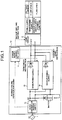
- FIG. 1 is a diagram illustrating, in outline, the configuration of a power supply apparatus according to an embodiment.
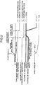
- FIG. 2 is a diagram explaining an operation performed by the power supply apparatus illustrated in FIG. 1 .
- FIG. 3 is a diagram illustrating, in outline, the configuration of a comparative example with which the configuration illustrated in FIG. 1 is compared.
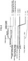
- FIG. 4 is a schematic diagram explaining an operation of the comparative example illustrated in FIG. 3 .
- a power supply apparatus 10 is connected to an alternating current (AC) power supply 1 and a load circuit 2.
- the load circuit 2 is, for example, an information processing apparatus, and the load voltage thereof is +1.2 V.
- the power supply apparatus 10 has therein a power supply control unit 11, an AC/DC (Alternating Current to Direct Current)converter power supply 12, a main power supply 13, a backup power supply 14, and a battery 15.
- a power supply control unit 11 an AC/DC (Alternating Current to Direct Current)converter power supply 12
- main power supply 13 a main power supply 13
- a backup power supply 14 a battery 15.
- the power supply control unit 11 is a control device that controls the operation of the power supply apparatus 10 and is also referred to as a service processor (SVP). Specifically, if the AC power supply 1 is stopped, the power supply control unit 11 receives a power failure notification signal from the AC/DC converter power supply 12; sends, to the load circuit 2, a backup shifting instruction; and controls the operation of the main power supply 13 and the backup power supply 14.
- SVP service processor
- the AC/DC converter power supply 12 is a converter that converts the output of the AC power supply 1 to a direct current (DC).
- the output of the AC/DC converter power supply 12 is supplied to the main power supply 13, the backup power supply 14, and the battery 15. Furthermore, if the AC/DC converter power supply 12 detects that the AC power supply 1 has stopped, the AC/DC converter power supply 12 sends a power failure notification signal to the power supply control unit 11.
- the battery 15 is a rechargeable battery charger that is charged using electrical power supplied from the AC/DC converter power supply 12.
- the main power supply 13 supplies, to the load circuit 2 using electrical power supplied from the AC/DC converter power supply 12, an output of 100 A at 1.2 V. Furthermore, if the AC power supply 1 is in the stopped state, the main power supply 13 supplies, to the load circuit 2 using electrical power stored in the battery 15, an output of 100 A at 1.2 V.
- the main power supply 13 is turned on and off in accordance with a turn on/off instruction from the power supply control unit 11.
- the turn on/off instruction is configured such that, for example, a "turn-on instruction" is indicated when the voltage value of a signal is in the high state, whereas a "turn-off instruction” is indicated when the voltage value of a signal is in the low state.
- the backup power supply 14 outputs a different voltage depending on the standby state and the start state.
- the standby state and the start state are switched in accordance with an instruction from the power supply control unit 11.
- the output voltage of the backup power supply 14 is lower than that of the main power supply 13.
- the output voltage of the backup power supply 14 in a standby state is set in such a manner that the upper limit of the voltage fluctuation range is smaller than the lower limit of the output voltage fluctuation range of the main power supply.
- the output voltage of the backup power supply 14 in the standby state can be outside the allowable range of the operation voltage of the load circuit 2.
- the backup power supply 14 that is in the start state supplies, to the load circuit 2 using electrical power supplied from the AC/DC converter power supply 12, an output of 10 A at 1.2 V. Furthermore, if the AC power supply 1 is in the stopped state, the backup power supply 14 in the start state supplies, to the load circuit 2 using electrical power stored in the battery 15, an output of 10 A at 1.2 V.
- the standby/start instruction is configured such that, for example, a "stand by instruction” is indicated when the voltage value of a signal is in the high state, and a “start instruction” is indicated when a voltage value of a signal is in the low state.
- each of the main power supply 13 and the backup power supply 14 has a backflow prevention diode to regulate the current direction so that it conforms to the direction of the load circuit 2.
- the power supply control unit 11 allows the main power supply 13 to operate and the backup power supply 14 to be in the standby state. Both the main power supply 13 and the backup power supply 14 are connected to the load circuit 2.
- the backup power supply 14 is in the standby state, the output voltage of the backup power supply 14 is lower than that of the main power supply 13. Accordingly, the main power supply 13 supplies electrical power to the load circuit 2.
- the load circuit 2 is in the normal operating state and performs arithmetic processing; therefore, a load current thereof is set, for example, to 100 A.
- the power supply control unit 11 starts a backup.
- the load circuit 2 gradually ends the arithmetic processing. In accordance with the end of the arithmetic processing, the load current is gradually reduced and stabilized at the amount of current that is used for memory retaining, in the example illustrated in FIG. 2 , at 10A.
- the power supply control unit 11 starts the backup power supply 14 a predetermined period of elapsed time after a backup is started.
- the predetermined period of time is the time required for the load current of the load circuit 2 to be sufficiently reduced.
- a predetermined period of time from when the backup is started until the backup power supply 14 is started can be set, in advance, as a backup shifting period.
- the power supply control unit 11 stops the main power supply 13 after the voltage of the backup power supply 14 has risen to 1.2 V.
- a power supply apparatus 20 of the comparative example illustrated in FIG. 3 is connected to the AC power supply 1 and a load circuit 3.
- the load circuit 3 is, for example, an information processing apparatus, and the load voltage thereof is +3.3 to 3.432 V.
- the power supply apparatus 20 has therein a power supply control unit 21, an AC/DC converter power supply 22, a main power supply 23, a backup power supply 24, and a battery 25.
- the power supply control unit 21 is a control device, i.e., a service processor, that controls the operation of the power supply apparatus 20. Specifically, if the AC power supply 1 is stopped, the power supply control unit 21 receives a power failure notification signal from the AC/DC converter power supply 22; sends, to the load circuit 3, a backup shifting instruction; and controls the operation of the main power supply 23 and the backup power supply 24.
- a control device i.e., a service processor
- the AC/DC converter power supply 22 is a converter that converts an output of the AC power supply 1 to a direct current.
- the output of the AC/DC converter power supply 22 is supplied to the main power supply 23, the backup power supply 24, and the battery 25. Furthermore, when the AC/DC converter power supply 22 detects that the AC power supply 1 has stopped, the AC/DC converter power supply 22 sends a power failure notification signal to the power supply control unit 21.
- the battery 25 is a rechargeable battery charger that is charged using electrical power supplied from the AC/DC converter power supply 22.
- the main power supply 23 supplies, to the load circuit 3 using electrical power supplied from the AC/DC converter power supply 22, an output of 100 A at 3.432 V. Furthermore, if the AC power supply 1 is in the stopped state, the main power supply 23 supplies, to the load circuit 3 using electrical power stored in the battery 25, an output of 100 A at 3.432 V.
- the main power supply 23 is turned on and off in accordance with a turn on/off instruction from the power supply control unit 21.
- the turn on/off instruction is configured such that, for example, a "turn-on instruction" is indicated when the voltage value of a signal is in a high state, whereas a "turn-off instruction” is indicated when the voltage value of a signal is in a low state.
- the backup power supply 24 supplies to the load circuit 3 using electrical power supplied from the AC/DC converter power supply 22, an output of 10 A at 3.3 V. Furthermore, if the AC power supply 1 is in the stopped state, the backup power supply 24 supplies, to the load circuit 3 using electrical power stored in the battery 25, an output of 10 A at 3.3 V.
- An on/off control of the backup power supply 24 is performed in accordance with a turn on/off instruction from the power supply control unit 21.
- the turn on/off instruction is configured such that, for example, a "turn-on instruction" is indicated when the voltage value of a signal is in a high state, whereas a "turn-off instruction” is indicated when the voltage value of a signal is in a low state.
- each of the main power supply 23 and the backup power supply 24 has a backflow prevention diode to regulate the current direction so that it conforms to the direction of the load circuit 3.
- the power supply control unit 21 allows both the main power supply 23 and the backup power supply 24 to be in the operating state. Both the main power supply 23 and the backup power supply 24 are connected to the load circuit 3. The output voltage of the backup power supply 24 is lower than that of the main power supply 23. Accordingly, if the main power supply 23 is in the operating state, the main power supply 23 supplies electrical power to the load circuit 3. Furthermore, the load circuit 3 is in the normal operating state and performs arithmetic processing; therefore, the load current thereof is set to 100 A.
- the power supply control unit 21 starts a backup.
- the load circuit 3 gradually ends the arithmetic processing. In accordance with the end of the arithmetic processing, the load current is gradually reduced and stabilized at the amount of current that is used for memory retaining, in the example illustrated in FIG. 4 , at 10 A.
- the power supply control unit 21 stops the main power supply 23 a predetermined period of elapsed time after a backup is started.
- the predetermined period of time is the time required for a load current of the load circuit 3 to be sufficiently reduced.
- a predetermined period of time from when the backup is started until the main power supply 23 is stopped can be set, in advance, as a backup shifting period.
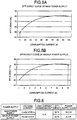
- FIGS. 5A and 5B are graphs exhibiting the efficiency of a main power supply and a backup power supply, respectively. As illustrated in FIGS. 5A and 5B , the efficiency of power conversion is improved as electrical power consumption of the power supply increases.
- the main power supplies 13 and 23 are designed on the assumption that the load current thereof is 100 A and that this corresponds to the consumption current in the normal operating state.
- the backup power supplies 14 and 24 are designed on the assumption that the load current thereof is 10 A and that this corresponds to a consumption current during a backup mode.
- FIG. 6 is a schematic diagram explaining a loss of the main power supply and the backup power supply during a backup mode in a comparative example. If electrical power is supplied from the main power supply 13 during a backup mode, the load current is too small, which causes the power conversion efficiency to be about 50%, resulting in an electrical power loss of 34.3 W. In contrast, with the backup power supply 24, the power conversion efficiency is about 80%, resulting in an electrical power loss of 8.3 W.
- the voltage of the main power supply 23 is set to +3.432 V, which is about 4% higher than the voltage of the backup power supply 24, i.e., +3.300 V, and electrical power is supplied form the main power supply 23 during a normal operation.
- both the output voltage of the main power supply 23 and that of the backup power supply 24 can be within the operating voltage allowable range of the load circuit 3.
- the main power supply 13 and the backup power supply 14 are configured to have the same set voltage.
- the power supply apparatus 10 operates the power supply control unit 11 to give a standby instruction with respect to the backup power supply 14 so that the backup power supply 14 is on standby at a voltage lower than that of the main power supply 13.
- the backup power supply 14 outputs a voltage even when it is in the standby state. The reason for that is to make sure that the backup power supply 14 has not failed its operation even in the normal operation state because if the backup power supply 14 fails and if that state is found when a backup is performed, the backup cannot be performed.
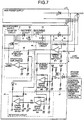
- FIG. 7 is a circuit diagram of the backup power supply 14.
- the backup power supply 14 has an inverter circuit 41, a rectifier circuit 42, a smoothing circuit 43, a feedback circuit 44, an output stabilizing circuit 45, a retention circuit 46, and a standby control circuit 47.
- the inverter circuit 41 converts the input voltage of the backup power supply 14 to a low voltage for loading.
- the rectifier circuit 42 and the smoothing circuit 43 convert it to a DC voltage.
- the feedback circuit 44 detects the load voltage.
- the output stabilizing circuit 45 maintains the load voltage at a constant voltage.
- the retention circuit 46 maintains the output voltage of the backup power supply 14 to prevent, even when the output set voltage of the main power supply 13 is high, the backup power supply 14 from being stopped due to the output voltage of the backup power supply 14 being made too low.
- the standby control circuit 47 If the standby control circuit 47 receives a standby instruction, the standby control circuit 47 allows the backup power supply 14 to be in the standby state by setting VA to -3 to -10% of VK. Furthermore, if the standby control circuit 47 receives a start instruction during a backup mode, the standby control circuit 47 controls the backup power supply 14 in such a manner that it outputs a load voltage of 1.2 V.
- FIG. 8 is a schematic diagram explaining an operation of the backup power supply 14.
- a standby instruction as a standby control signal is input to the standby control circuit 47.
- a transistor Q1 enters the on state, and the output of an operational amplifier M5 in the standby control circuit 47 becomes high.
- the output of an operational amplifier M1 in the feedback circuit 44 becomes high, and an operational amplifier M2 in the output stabilizing circuit 45 acts to lower the VA.
- the operational amplifier M3 limits the lowest value of VA by controlling the operational amplifier M2.
- a start instruction is input to the standby control circuit 47 as a stand by control signal. Accordingly, a transistor Q1 enters the off state.
- the output of the operational amplifier M5 in the standby control circuit 47 becomes a voltage equal to that of the positive (+) terminal of the operational amplifier M1 in the feedback circuit 44, i.e., a voltage fed back from the load voltage
- the output of the operational amplifier M1 in the feedback circuit 44 feeds back the state of the load voltage.
- the operational amplifier M2 in the output stabilizing circuit 45 keeps the load voltage constant on the basis of information on the load voltage received from the operational amplifier M1 in the feedback circuit 44.
- the standby control circuit 47 controls the voltage during the standby state in accordance with the output voltage of the main power supply 13; however, the configuration is not limited thereto.
- FIG. 9 is a flowchart explaining an operation performed by the power supply control unit 11 when a state shifts to a backup.
- the power supply control unit 11 operates the main power supply 13 and observes any power failure while allowing the backup power supply 14 to be in the standby state.
- the power supply control unit 11 When the power supply control unit 11 receives a power failure notification signal (Yes at S101), the power supply control unit 11 sends, to the load circuit 2, a backup shifting instruction to allow the load circuit 2 to perform a backup shifting process (S102). Then, the power supply control unit 11 observes whether a backup shifting period ends. If the backup shifting period ends (Yes at S103), the power supply control unit 11 sends, to the backup power supply 14, a start signal (S104). Thereafter, if the backup power supply 14 is started (Yes at S105), the power supply control unit 11 stops the main power supply 13 (S106) and ends the shift to the backup state.
- FIG. 10 is a flowchart explaining an operation performed by the power supply control unit 11 when a backup is restored.
- the power supply control unit 11 stops the main power supply 13 and observes the restoration of power (power failure recovery) while allowing the backup power supply 14 to be in the start state.
- the power supply control unit 11 sends a start signal to the main power supply 13 (S202). Then the power supply control unit 11 checks whether the main power supply 13 is started (S203). If the main power supply 13 is successfully started (Yes at S203), the power supply control unit 11 shifts the backup power supply 14 to the standby state (S204). Subsequently, after the backup power supply 14 shifts to the standby state (Yes at S205), the power supply control unit 11 allows the load circuit 2 to perform a restoring process for restoring the state from the backup state (S206) and returns to the normal operation.
- the main power supply 13 and the backup power supply 14 are configured to have the same set voltage.
- the power supply control unit 11 gives a standby instruction, to the backup power supply 14, to allow the backup power supply 14 to be on standby at a voltage lower than that of the main power supply 13.
- the present invention it is possible to efficiently switch, with respect to a load circuit having a low load voltage, between a first power supply circuit and a second power supply circuit. Furthermore, it is also possible to obtain a power supply apparatus and a power supply control method that implements low electrical power consumption by reducing electrical power loss.
Landscapes
- Business, Economics & Management (AREA)
- Emergency Management (AREA)
- Engineering & Computer Science (AREA)
- Power Engineering (AREA)
- Stand-By Power Supply Arrangements (AREA)
- Dc-Dc Converters (AREA)
Claims (6)
- Appareil d'alimentation électrique (10 ; 20) comprenant :un circuit convertisseur (12 ; 22) configuré pour convertir une sortie en courant alternatif d'une alimentation électrique AC (1) en un courant continu ;une batterie (15 ; 25) qui est configurée pour être chargée par la sortie en courant continu provenant du circuit convertisseur (12 ; 22) ;un premier circuit d'alimentation électrique (13 ; 23) configuré pour délivrer une première tension qui se trouve dans une plage admissible d'une tension de charge d'un circuit de charge (2 ; 3) à partir du circuit convertisseur (12 ; 22) ou de la batterie (15 ; 25) dans le circuit de charge (2 ; 3) ;un second circuit d'alimentation électrique (14 ; 24) configuré pour délivrer une tension parmi une deuxième tension qui est dans la plage admissible et une troisième tension qui est inférieure à la première tension à partir du circuit convertisseur (12 ; 22) ou de la batterie (15 ; 25) dans le circuit de charge (2 ; 3) ; etune unité de commande d'alimentation électrique (11 ; 21) configurée pour amener le premier circuit d'alimentation électrique (13 ; 23) à délivrer en sortie la première tension et le second circuit d'alimentation électrique (14 ; 24) à délivrer en sortie la troisième tension lorsque le courant alternatif est délivré en sortie par l'alimentation électrique AC (1), et est en outre configurée pour amener le second circuit d'alimentation électrique (14 ; 24) à délivrer en sortie la deuxième tension et le premier circuit d'alimentation électrique (13 ; 23) à arrêter de délivrer en sortie la première tension, lorsque l'alimentation électrique AC (1) est arrêtée,caractérisé en ce quele premier circuit d'alimentation électrique (13 ; 23) et le second circuit d'alimentation électrique (14 ; 24) comprennent une diode de prévention de reflux configurée pour réguler une direction de courant dans l'appareil d'alimentation électrique (10 ; 20) pour se conformer à une direction de courant du circuit de charge (2 ; 3), etdans lequel le second circuit d'alimentation électrique (14 ; 24) est configuré pour délivrer en sortie une quatrième tension qui est inférieure à la première tension lorsque l'appareil d'alimentation électrique (10 ; 20) est dans un état de veille, la quatrième tension étant établie de sorte que la limite supérieure d'une plage de fluctuation de la quatrième tension est inférieure à la limite inférieure d'une plage de fluctuation de la première tension.
- Appareil d'alimentation électrique (10 ; 20) selon la revendication 1, dans lequel la première tension est la même que la deuxième tension.
- Appareil d'alimentation électrique (10 ; 20) selon la revendication 1 ou 2, dans lequel la troisième tension est inférieure à une limite inférieure de la plage admissible.
- Appareil d'alimentation électrique (10 ; 20) selon l'une quelconque des revendications 1 à 3, dans lequel le second circuit d'alimentation électrique (14 ; 24) comprend un circuit de commande qui est configuré pour recevoir la première tension afin de commander la troisième tension.
- Appareil d'alimentation électrique (10 ; 20) selon l'une quelconque des revendications 1 à 4, dans lequel l'unité de commande d'alimentation électrique (11 ; 21) est configurée pour ordonner au circuit de charge (2 ; 3) de passer dans un état de secours et ensuite permettre au second circuit d'alimentation électrique (14 ; 24) de délivrer en sortie la deuxième tension dans le circuit de charge (2 ; 3), lorsqu'il est détecté que l'alimentation électrique AC (1) est arrêtée.
- Procédé de commande d'une puissance d'un appareil d'alimentation électrique (10 ; 20) pour délivrer un courant à un circuit de charge (2 ; 3), le procédé comprenant les étapes consistant à :convertir une sortie en courant alternatif d'une alimentation électrique AC (1) en un courant continu ;charger une batterie (15 ; 25) incluse dans l'appareil d'alimentation électrique (10 ; 20) en utilisant la sortie en courant continu provenant du circuit convertisseur (12 ; 22) ;délivrer en sortie une première tension qui se trouve dans une plage admissible d'une tension de charge du circuit de charge (2 ; 3) à partir du circuit convertisseur (12 ; 22) ou de la batterie (15 ; 25) dans le circuit de charge (2 ; 3) par un premier circuit d'alimentation électrique (13 ; 23) inclus dans l'appareil d'alimentation électrique (10 ; 20) ;délivrer en sortie une tension parmi une deuxième tension qui est dans la plage admissible et une troisième tension qui est inférieure à la première tension à partir du circuit convertisseur (12 ; 22) ou de la batterie (15 ; 25) dans le circuit de charge (2 ; 3) par un second circuit d'alimentation électrique (14 ; 24) inclus dans l'appareil d'alimentation électrique (10 ; 20) ; etamener le premier circuit d'alimentation électrique (13 ; 23) à délivrer en sortie la première tension et amener le second circuit d'alimentation électrique (14 ; 24) à délivrer en sortie la troisième tension par l'intermédiaire d'une unité de commande d'alimentation électrique (11 ; 21) incluse dans l'appareil d'alimentation électrique (10 ; 20), lorsque le courant alternatif est délivré en sortie par l'alimentation électrique AC (1) ;amener le second circuit d'alimentation électrique (14 ; 24) à délivrer en sortie la deuxième tension et amener le premier circuit d'alimentation électrique (13 ; 23) à arrêter de délivrer en sortie la première tension par l'intermédiaire de l'unité de commande d'alimentation électrique (11 ; 21), lorsque l'alimentation électrique AC (1) est arrêtée ; etcaractérisé par l'étape consistant àdans le premier circuit d'alimentation électrique (13 ; 23) et le second circuit d'alimentation électrique (14 ; 24), réguler par une diode de prévention de reflux une direction de courant dans l'appareil d'alimentation électrique (10 ; 20) pour se conformer à une direction de courant du circuit de charge (2 ; 3), etdans lequel le second circuit d'alimentation électrique (14 ; 24) délivre en sortie une quatrième tension qui est inférieure à la première tension lorsque l'appareil d'alimentation électrique (10 ; 20) est dans un état de veille, la quatrième tension étant établie de telle sorte que la limite supérieure d'une plage de fluctuation de la quatrième tension est inférieure à la limite inférieure d'une plage de fluctuation de la première tension.
Applications Claiming Priority (1)
| Application Number | Priority Date | Filing Date | Title |
|---|---|---|---|
| JP2009164727A JP5129788B2 (ja) | 2009-07-13 | 2009-07-13 | 電源装置および電源制御方法 |
Publications (3)
| Publication Number | Publication Date |
|---|---|
| EP2276143A2 EP2276143A2 (fr) | 2011-01-19 |
| EP2276143A3 EP2276143A3 (fr) | 2014-06-04 |
| EP2276143B1 true EP2276143B1 (fr) | 2017-11-01 |
Family
ID=42983220
Family Applications (1)
| Application Number | Title | Priority Date | Filing Date |
|---|---|---|---|
| EP10169260.6A Not-in-force EP2276143B1 (fr) | 2009-07-13 | 2010-07-12 | Appareil d'alimentation électrique et procédé de contrôle d'alimentation électrique |
Country Status (3)
| Country | Link |
|---|---|
| US (1) | US8484491B2 (fr) |
| EP (1) | EP2276143B1 (fr) |
| JP (1) | JP5129788B2 (fr) |
Families Citing this family (10)
| Publication number | Priority date | Publication date | Assignee | Title |
|---|---|---|---|---|
| JP5604856B2 (ja) * | 2009-11-18 | 2014-10-15 | 富士通株式会社 | 制御装置、制御方法および制御プログラム |
| US9019067B2 (en) * | 2010-12-30 | 2015-04-28 | Sargent Manufacturing Company | Electronic lock with power failure control circuit |
| TWI446685B (zh) * | 2011-11-03 | 2014-07-21 | Pegatron Corp | 備援式電源控制系統 |
| JP2013152440A (ja) * | 2011-12-29 | 2013-08-08 | Ricoh Co Ltd | 電源装置および画像形成装置 |
| JP2014128142A (ja) | 2012-12-27 | 2014-07-07 | Fdk Corp | 無停電電源装置 |
| DK3008108T3 (da) * | 2013-06-12 | 2020-10-26 | Basf Se | Fremgangsmåde til fremstilling af delaromatiske copolyamider med højt diaminoverskud |
| TWI505603B (zh) * | 2013-12-23 | 2015-10-21 | Fsp Technology Inc | 電源供應裝置及其電源供應方法 |
| CN104201762B (zh) * | 2014-08-04 | 2016-06-22 | 珠海普恩瑞电力科技有限公司 | 一种电力箱变专用操作电源 |
| CN104391559A (zh) * | 2014-11-11 | 2015-03-04 | 广东省电子信息产业集团有限公司 | 备用电源的控制方法和控制系统 |
| EP3893360A1 (fr) * | 2020-04-08 | 2021-10-13 | Rohde & Schwarz GmbH & Co. KG | Alimentation électrique, dispositif de communication et procédé de commande d'une alimentation électrique |
Citations (1)
| Publication number | Priority date | Publication date | Assignee | Title |
|---|---|---|---|---|
| US6225708B1 (en) * | 1998-06-05 | 2001-05-01 | International Business Machine Corporation | Uninterruptable power supply |
Family Cites Families (10)
| Publication number | Priority date | Publication date | Assignee | Title |
|---|---|---|---|---|
| JPH06351245A (ja) * | 1993-06-02 | 1994-12-22 | Nippon Electric Ind Co Ltd | 直流無停電電源装置 |
| JPH0715888A (ja) | 1993-06-23 | 1995-01-17 | Canon Inc | バッテリー・バックアップ電源装置 |
| JPH07336915A (ja) | 1994-05-31 | 1995-12-22 | Okamura Kenkyusho:Kk | 無停電電源装置 |
| JPH08205422A (ja) * | 1995-01-18 | 1996-08-09 | Fujitsu Ltd | 停電バックアップ手段を備えた電源装置 |
| JP3466789B2 (ja) | 1995-07-20 | 2003-11-17 | キヤノン株式会社 | 電源バックアップ装置 |
| JPH09200974A (ja) * | 1996-01-12 | 1997-07-31 | Origin Electric Co Ltd | バックアップ用蓄電池を備えた直流電源装置 |
| JP2005227988A (ja) * | 2004-02-12 | 2005-08-25 | Hitachi Ltd | ディスクアレイ装置、及びディスクアレイ装置の電源バックアップ方法 |
| JP2005228254A (ja) * | 2004-02-16 | 2005-08-25 | Hitachi Ltd | 記憶装置 |
| US7287175B2 (en) * | 2004-07-19 | 2007-10-23 | Tellabs Petaluma, Inc. | Optical network terminal with low-power sleep logic that substantially extends the life of the battery after the AC main power supply has been lost |
| US7812582B2 (en) * | 2006-09-14 | 2010-10-12 | Qualcomm Incorporated | System and method of power distribution control of an integrated circuit |
-
2009
- 2009-07-13 JP JP2009164727A patent/JP5129788B2/ja not_active Expired - Fee Related
-
2010
- 2010-07-12 EP EP10169260.6A patent/EP2276143B1/fr not_active Not-in-force
- 2010-07-12 US US12/805,097 patent/US8484491B2/en not_active Expired - Fee Related
Patent Citations (1)
| Publication number | Priority date | Publication date | Assignee | Title |
|---|---|---|---|---|
| US6225708B1 (en) * | 1998-06-05 | 2001-05-01 | International Business Machine Corporation | Uninterruptable power supply |
Also Published As
| Publication number | Publication date |
|---|---|
| EP2276143A2 (fr) | 2011-01-19 |
| US20110010568A1 (en) | 2011-01-13 |
| JP5129788B2 (ja) | 2013-01-30 |
| JP2011024288A (ja) | 2011-02-03 |
| US8484491B2 (en) | 2013-07-09 |
| EP2276143A3 (fr) | 2014-06-04 |
Similar Documents
| Publication | Publication Date | Title |
|---|---|---|
| EP2276143B1 (fr) | Appareil d'alimentation électrique et procédé de contrôle d'alimentation électrique | |
| US6225708B1 (en) | Uninterruptable power supply | |
| US9331523B2 (en) | Power control device and power control method | |
| JP5640387B2 (ja) | 電源装置 | |
| KR101117706B1 (ko) | 전력 공급 장치 | |
| US7932636B2 (en) | Automatic start-up circuit and uninterruptible power supply apparatus having such automatic start-up circuit | |
| EP2750262B1 (fr) | Dispositif d'alimentation sans coupure | |
| JP6876992B2 (ja) | 車両電源装置 | |
| JP2012191838A (ja) | 電池パック、電動工具、電池パックと電動工具とを接続するアダプタ、及び、電動工具システム | |
| JP2008092768A (ja) | 放電器、放電制御方法、放電制御プログラム並びにプログラム記録媒体 | |
| JP2009131101A (ja) | 電力供給装置及び電力供給装置における過放電制御方法 | |
| EP3168961B1 (fr) | Dispositif de source d'alimentation sans coupure | |
| US8977406B2 (en) | Power supply system, power supply control method, power supply control device and program | |
| JP5073436B2 (ja) | 無瞬断バックアップ電源 | |
| EP3846314A2 (fr) | Stratégie de commande d'onduleur pour une charge lourde transitoire | |
| JP5587941B2 (ja) | 無停電電源装置及び無停電電源供給方法 | |
| EP1513240A2 (fr) | Appareil d'alimentation de puissance de secours | |
| JP5426440B2 (ja) | 直流給電システム | |
| JP5638894B2 (ja) | 電力変換装置及び直流給電システム | |
| JP2006006045A (ja) | 電力供給方法及び無停電電源システム | |
| JP2004139810A (ja) | 燃料電池の給電システム | |
| JP2012100517A (ja) | バックアップ電源装置及び計算機システム | |
| JP2500592B2 (ja) | 無停電電源装置 | |
| JP6975768B2 (ja) | 電圧変換装置 | |
| US8354761B2 (en) | Transforming device, electronic apparatus, and power supply system including the same |
Legal Events
| Date | Code | Title | Description |
|---|---|---|---|
| PUAI | Public reference made under article 153(3) epc to a published international application that has entered the european phase |
Free format text: ORIGINAL CODE: 0009012 |
|
| AK | Designated contracting states |
Kind code of ref document: A2 Designated state(s): AL AT BE BG CH CY CZ DE DK EE ES FI FR GB GR HR HU IE IS IT LI LT LU LV MC MK MT NL NO PL PT RO SE SI SK SM TR |
|
| AX | Request for extension of the european patent |
Extension state: BA ME RS |
|
| PUAL | Search report despatched |
Free format text: ORIGINAL CODE: 0009013 |
|
| AK | Designated contracting states |
Kind code of ref document: A3 Designated state(s): AL AT BE BG CH CY CZ DE DK EE ES FI FR GB GR HR HU IE IS IT LI LT LU LV MC MK MT NL NO PL PT RO SE SI SK SM TR |
|
| AX | Request for extension of the european patent |
Extension state: BA ME RS |
|
| RIC1 | Information provided on ipc code assigned before grant |
Ipc: H02J 9/06 20060101AFI20140425BHEP |
|
| 17P | Request for examination filed |
Effective date: 20140818 |
|
| RBV | Designated contracting states (corrected) |
Designated state(s): AL AT BE BG CH CY CZ DE DK EE ES FI FR GB GR HR HU IE IS IT LI LT LU LV MC MK MT NL NO PL PT RO SE SI SK SM TR |
|
| 17Q | First examination report despatched |
Effective date: 20160527 |
|
| GRAP | Despatch of communication of intention to grant a patent |
Free format text: ORIGINAL CODE: EPIDOSNIGR1 |
|
| STAA | Information on the status of an ep patent application or granted ep patent |
Free format text: STATUS: GRANT OF PATENT IS INTENDED |
|
| RIC1 | Information provided on ipc code assigned before grant |
Ipc: H02J 9/06 20060101AFI20170510BHEP Ipc: H02J 9/00 20060101ALN20170510BHEP |
|
| INTG | Intention to grant announced |
Effective date: 20170523 |
|
| GRAS | Grant fee paid |
Free format text: ORIGINAL CODE: EPIDOSNIGR3 |
|
| GRAA | (expected) grant |
Free format text: ORIGINAL CODE: 0009210 |
|
| STAA | Information on the status of an ep patent application or granted ep patent |
Free format text: STATUS: THE PATENT HAS BEEN GRANTED |
|
| AK | Designated contracting states |
Kind code of ref document: B1 Designated state(s): AL AT BE BG CH CY CZ DE DK EE ES FI FR GB GR HR HU IE IS IT LI LT LU LV MC MK MT NL NO PL PT RO SE SI SK SM TR |
|
| REG | Reference to a national code |
Ref country code: GB Ref legal event code: FG4D |
|
| REG | Reference to a national code |
Ref country code: CH Ref legal event code: EP Ref country code: AT Ref legal event code: REF Ref document number: 942958 Country of ref document: AT Kind code of ref document: T Effective date: 20171115 |
|
| REG | Reference to a national code |
Ref country code: IE Ref legal event code: FG4D |
|
| REG | Reference to a national code |
Ref country code: DE Ref legal event code: R096 Ref document number: 602010046325 Country of ref document: DE |
|
| REG | Reference to a national code |
Ref country code: NL Ref legal event code: MP Effective date: 20171101 |
|
| REG | Reference to a national code |
Ref country code: LT Ref legal event code: MG4D |
|
| REG | Reference to a national code |
Ref country code: AT Ref legal event code: MK05 Ref document number: 942958 Country of ref document: AT Kind code of ref document: T Effective date: 20171101 |
|
| PG25 | Lapsed in a contracting state [announced via postgrant information from national office to epo] |
Ref country code: NO Free format text: LAPSE BECAUSE OF FAILURE TO SUBMIT A TRANSLATION OF THE DESCRIPTION OR TO PAY THE FEE WITHIN THE PRESCRIBED TIME-LIMIT Effective date: 20180201 Ref country code: SE Free format text: LAPSE BECAUSE OF FAILURE TO SUBMIT A TRANSLATION OF THE DESCRIPTION OR TO PAY THE FEE WITHIN THE PRESCRIBED TIME-LIMIT Effective date: 20171101 Ref country code: LT Free format text: LAPSE BECAUSE OF FAILURE TO SUBMIT A TRANSLATION OF THE DESCRIPTION OR TO PAY THE FEE WITHIN THE PRESCRIBED TIME-LIMIT Effective date: 20171101 Ref country code: NL Free format text: LAPSE BECAUSE OF FAILURE TO SUBMIT A TRANSLATION OF THE DESCRIPTION OR TO PAY THE FEE WITHIN THE PRESCRIBED TIME-LIMIT Effective date: 20171101 Ref country code: FI Free format text: LAPSE BECAUSE OF FAILURE TO SUBMIT A TRANSLATION OF THE DESCRIPTION OR TO PAY THE FEE WITHIN THE PRESCRIBED TIME-LIMIT Effective date: 20171101 Ref country code: ES Free format text: LAPSE BECAUSE OF FAILURE TO SUBMIT A TRANSLATION OF THE DESCRIPTION OR TO PAY THE FEE WITHIN THE PRESCRIBED TIME-LIMIT Effective date: 20171101 |
|
| REG | Reference to a national code |
Ref country code: FR Ref legal event code: PLFP Year of fee payment: 9 |
|
| PG25 | Lapsed in a contracting state [announced via postgrant information from national office to epo] |
Ref country code: AT Free format text: LAPSE BECAUSE OF FAILURE TO SUBMIT A TRANSLATION OF THE DESCRIPTION OR TO PAY THE FEE WITHIN THE PRESCRIBED TIME-LIMIT Effective date: 20171101 Ref country code: HR Free format text: LAPSE BECAUSE OF FAILURE TO SUBMIT A TRANSLATION OF THE DESCRIPTION OR TO PAY THE FEE WITHIN THE PRESCRIBED TIME-LIMIT Effective date: 20171101 Ref country code: BG Free format text: LAPSE BECAUSE OF FAILURE TO SUBMIT A TRANSLATION OF THE DESCRIPTION OR TO PAY THE FEE WITHIN THE PRESCRIBED TIME-LIMIT Effective date: 20180201 Ref country code: IS Free format text: LAPSE BECAUSE OF FAILURE TO SUBMIT A TRANSLATION OF THE DESCRIPTION OR TO PAY THE FEE WITHIN THE PRESCRIBED TIME-LIMIT Effective date: 20180301 Ref country code: GR Free format text: LAPSE BECAUSE OF FAILURE TO SUBMIT A TRANSLATION OF THE DESCRIPTION OR TO PAY THE FEE WITHIN THE PRESCRIBED TIME-LIMIT Effective date: 20180202 Ref country code: LV Free format text: LAPSE BECAUSE OF FAILURE TO SUBMIT A TRANSLATION OF THE DESCRIPTION OR TO PAY THE FEE WITHIN THE PRESCRIBED TIME-LIMIT Effective date: 20171101 |
|
| PG25 | Lapsed in a contracting state [announced via postgrant information from national office to epo] |
Ref country code: SK Free format text: LAPSE BECAUSE OF FAILURE TO SUBMIT A TRANSLATION OF THE DESCRIPTION OR TO PAY THE FEE WITHIN THE PRESCRIBED TIME-LIMIT Effective date: 20171101 Ref country code: DK Free format text: LAPSE BECAUSE OF FAILURE TO SUBMIT A TRANSLATION OF THE DESCRIPTION OR TO PAY THE FEE WITHIN THE PRESCRIBED TIME-LIMIT Effective date: 20171101 Ref country code: CZ Free format text: LAPSE BECAUSE OF FAILURE TO SUBMIT A TRANSLATION OF THE DESCRIPTION OR TO PAY THE FEE WITHIN THE PRESCRIBED TIME-LIMIT Effective date: 20171101 Ref country code: CY Free format text: LAPSE BECAUSE OF FAILURE TO SUBMIT A TRANSLATION OF THE DESCRIPTION OR TO PAY THE FEE WITHIN THE PRESCRIBED TIME-LIMIT Effective date: 20171101 Ref country code: EE Free format text: LAPSE BECAUSE OF FAILURE TO SUBMIT A TRANSLATION OF THE DESCRIPTION OR TO PAY THE FEE WITHIN THE PRESCRIBED TIME-LIMIT Effective date: 20171101 |
|
| REG | Reference to a national code |
Ref country code: DE Ref legal event code: R097 Ref document number: 602010046325 Country of ref document: DE |
|
| PG25 | Lapsed in a contracting state [announced via postgrant information from national office to epo] |
Ref country code: PL Free format text: LAPSE BECAUSE OF FAILURE TO SUBMIT A TRANSLATION OF THE DESCRIPTION OR TO PAY THE FEE WITHIN THE PRESCRIBED TIME-LIMIT Effective date: 20171101 Ref country code: SM Free format text: LAPSE BECAUSE OF FAILURE TO SUBMIT A TRANSLATION OF THE DESCRIPTION OR TO PAY THE FEE WITHIN THE PRESCRIBED TIME-LIMIT Effective date: 20171101 Ref country code: IT Free format text: LAPSE BECAUSE OF FAILURE TO SUBMIT A TRANSLATION OF THE DESCRIPTION OR TO PAY THE FEE WITHIN THE PRESCRIBED TIME-LIMIT Effective date: 20171101 Ref country code: RO Free format text: LAPSE BECAUSE OF FAILURE TO SUBMIT A TRANSLATION OF THE DESCRIPTION OR TO PAY THE FEE WITHIN THE PRESCRIBED TIME-LIMIT Effective date: 20171101 |
|
| PLBE | No opposition filed within time limit |
Free format text: ORIGINAL CODE: 0009261 |
|
| STAA | Information on the status of an ep patent application or granted ep patent |
Free format text: STATUS: NO OPPOSITION FILED WITHIN TIME LIMIT |
|
| 26N | No opposition filed |
Effective date: 20180802 |
|
| PG25 | Lapsed in a contracting state [announced via postgrant information from national office to epo] |
Ref country code: SI Free format text: LAPSE BECAUSE OF FAILURE TO SUBMIT A TRANSLATION OF THE DESCRIPTION OR TO PAY THE FEE WITHIN THE PRESCRIBED TIME-LIMIT Effective date: 20171101 |
|
| REG | Reference to a national code |
Ref country code: CH Ref legal event code: PL |
|
| PG25 | Lapsed in a contracting state [announced via postgrant information from national office to epo] |
Ref country code: LU Free format text: LAPSE BECAUSE OF NON-PAYMENT OF DUE FEES Effective date: 20180712 Ref country code: MC Free format text: LAPSE BECAUSE OF FAILURE TO SUBMIT A TRANSLATION OF THE DESCRIPTION OR TO PAY THE FEE WITHIN THE PRESCRIBED TIME-LIMIT Effective date: 20171101 |
|
| REG | Reference to a national code |
Ref country code: BE Ref legal event code: MM Effective date: 20180731 |
|
| REG | Reference to a national code |
Ref country code: IE Ref legal event code: MM4A |
|
| PG25 | Lapsed in a contracting state [announced via postgrant information from national office to epo] |
Ref country code: LI Free format text: LAPSE BECAUSE OF NON-PAYMENT OF DUE FEES Effective date: 20180731 Ref country code: CH Free format text: LAPSE BECAUSE OF NON-PAYMENT OF DUE FEES Effective date: 20180731 Ref country code: IE Free format text: LAPSE BECAUSE OF NON-PAYMENT OF DUE FEES Effective date: 20180712 |
|
| PG25 | Lapsed in a contracting state [announced via postgrant information from national office to epo] |
Ref country code: BE Free format text: LAPSE BECAUSE OF NON-PAYMENT OF DUE FEES Effective date: 20180731 |
|
| PG25 | Lapsed in a contracting state [announced via postgrant information from national office to epo] |
Ref country code: MT Free format text: LAPSE BECAUSE OF NON-PAYMENT OF DUE FEES Effective date: 20180712 |
|
| PG25 | Lapsed in a contracting state [announced via postgrant information from national office to epo] |
Ref country code: TR Free format text: LAPSE BECAUSE OF FAILURE TO SUBMIT A TRANSLATION OF THE DESCRIPTION OR TO PAY THE FEE WITHIN THE PRESCRIBED TIME-LIMIT Effective date: 20171101 |
|
| PG25 | Lapsed in a contracting state [announced via postgrant information from national office to epo] |
Ref country code: HU Free format text: LAPSE BECAUSE OF FAILURE TO SUBMIT A TRANSLATION OF THE DESCRIPTION OR TO PAY THE FEE WITHIN THE PRESCRIBED TIME-LIMIT; INVALID AB INITIO Effective date: 20100712 Ref country code: PT Free format text: LAPSE BECAUSE OF FAILURE TO SUBMIT A TRANSLATION OF THE DESCRIPTION OR TO PAY THE FEE WITHIN THE PRESCRIBED TIME-LIMIT Effective date: 20171101 |
|
| PG25 | Lapsed in a contracting state [announced via postgrant information from national office to epo] |
Ref country code: MK Free format text: LAPSE BECAUSE OF NON-PAYMENT OF DUE FEES Effective date: 20171101 |
|
| PG25 | Lapsed in a contracting state [announced via postgrant information from national office to epo] |
Ref country code: AL Free format text: LAPSE BECAUSE OF FAILURE TO SUBMIT A TRANSLATION OF THE DESCRIPTION OR TO PAY THE FEE WITHIN THE PRESCRIBED TIME-LIMIT Effective date: 20171101 |
|
| REG | Reference to a national code |
Ref country code: DE Ref legal event code: R082 Ref document number: 602010046325 Country of ref document: DE Representative=s name: HL KEMPNER PATENTANWALT, RECHTSANWALT, SOLICIT, DE |
|
| PGFP | Annual fee paid to national office [announced via postgrant information from national office to epo] |
Ref country code: FR Payment date: 20210611 Year of fee payment: 12 |
|
| PGFP | Annual fee paid to national office [announced via postgrant information from national office to epo] |
Ref country code: GB Payment date: 20210616 Year of fee payment: 12 |
|
| PGFP | Annual fee paid to national office [announced via postgrant information from national office to epo] |
Ref country code: DE Payment date: 20210616 Year of fee payment: 12 |
|
| REG | Reference to a national code |
Ref country code: DE Ref legal event code: R119 Ref document number: 602010046325 Country of ref document: DE |
|
| GBPC | Gb: european patent ceased through non-payment of renewal fee |
Effective date: 20220712 |
|
| PG25 | Lapsed in a contracting state [announced via postgrant information from national office to epo] |
Ref country code: FR Free format text: LAPSE BECAUSE OF NON-PAYMENT OF DUE FEES Effective date: 20220731 |
|
| PG25 | Lapsed in a contracting state [announced via postgrant information from national office to epo] |
Ref country code: GB Free format text: LAPSE BECAUSE OF NON-PAYMENT OF DUE FEES Effective date: 20220712 Ref country code: DE Free format text: LAPSE BECAUSE OF NON-PAYMENT OF DUE FEES Effective date: 20230201 |