EP2274660B1 - Force-feedback interface with improved sensations - Google Patents
Force-feedback interface with improved sensations Download PDFInfo
- Publication number
- EP2274660B1 EP2274660B1 EP09738100.8A EP09738100A EP2274660B1 EP 2274660 B1 EP2274660 B1 EP 2274660B1 EP 09738100 A EP09738100 A EP 09738100A EP 2274660 B1 EP2274660 B1 EP 2274660B1
- Authority
- EP
- European Patent Office
- Prior art keywords
- magnetic field
- generating
- fluid
- interface according
- shaft
- Prior art date
- Legal status (The legal status is an assumption and is not a legal conclusion. Google has not performed a legal analysis and makes no representation as to the accuracy of the status listed.)
- Active
Links
- 230000035807 sensation Effects 0.000 title description 2
- 230000005291 magnetic effect Effects 0.000 claims description 99
- 239000012530 fluid Substances 0.000 claims description 64
- 230000003993 interaction Effects 0.000 claims description 30
- 238000006073 displacement reaction Methods 0.000 claims description 11
- 230000001133 acceleration Effects 0.000 claims description 9
- 230000003287 optical effect Effects 0.000 claims description 8
- 239000000696 magnetic material Substances 0.000 claims description 7
- 230000002829 reductive effect Effects 0.000 description 6
- 239000000463 material Substances 0.000 description 5
- 230000000670 limiting effect Effects 0.000 description 4
- 238000007789 sealing Methods 0.000 description 3
- 238000004378 air conditioning Methods 0.000 description 2
- 239000003302 ferromagnetic material Substances 0.000 description 2
- 230000006870 function Effects 0.000 description 2
- 230000005415 magnetization Effects 0.000 description 2
- 238000005259 measurement Methods 0.000 description 2
- 230000001953 sensory effect Effects 0.000 description 2
- 230000008859 change Effects 0.000 description 1
- 238000006243 chemical reaction Methods 0.000 description 1
- 238000004891 communication Methods 0.000 description 1
- 230000036461 convulsion Effects 0.000 description 1
- 230000008878 coupling Effects 0.000 description 1
- 238000010168 coupling process Methods 0.000 description 1
- 238000005859 coupling reaction Methods 0.000 description 1
- 238000013016 damping Methods 0.000 description 1
- 239000006185 dispersion Substances 0.000 description 1
- 230000000694 effects Effects 0.000 description 1
- 230000005611 electricity Effects 0.000 description 1
- 239000011554 ferrofluid Substances 0.000 description 1
- 230000010354 integration Effects 0.000 description 1
- 230000002452 interceptive effect Effects 0.000 description 1
- 239000007788 liquid Substances 0.000 description 1
- 230000007246 mechanism Effects 0.000 description 1
- 238000005192 partition Methods 0.000 description 1
- 230000000149 penetrating effect Effects 0.000 description 1
- 230000035699 permeability Effects 0.000 description 1
- 230000000284 resting effect Effects 0.000 description 1
- 230000035945 sensitivity Effects 0.000 description 1
- 230000003068 static effect Effects 0.000 description 1
- 238000010200 validation analysis Methods 0.000 description 1
- 230000000007 visual effect Effects 0.000 description 1
Images


Classifications
-
- G—PHYSICS
- G05—CONTROLLING; REGULATING
- G05G—CONTROL DEVICES OR SYSTEMS INSOFAR AS CHARACTERISED BY MECHANICAL FEATURES ONLY
- G05G1/00—Controlling members, e.g. knobs or handles; Assemblies or arrangements thereof; Indicating position of controlling members
- G05G1/08—Controlling members for hand actuation by rotary movement, e.g. hand wheels
-
- B60K35/10—
-
- B60K35/25—
-
- F—MECHANICAL ENGINEERING; LIGHTING; HEATING; WEAPONS; BLASTING
- F16—ENGINEERING ELEMENTS AND UNITS; GENERAL MEASURES FOR PRODUCING AND MAINTAINING EFFECTIVE FUNCTIONING OF MACHINES OR INSTALLATIONS; THERMAL INSULATION IN GENERAL
- F16F—SPRINGS; SHOCK-ABSORBERS; MEANS FOR DAMPING VIBRATION
- F16F9/00—Springs, vibration-dampers, shock-absorbers, or similarly-constructed movement-dampers using a fluid or the equivalent as damping medium
- F16F9/32—Details
- F16F9/53—Means for adjusting damping characteristics by varying fluid viscosity, e.g. electromagnetically
- F16F9/535—Magnetorheological [MR] fluid dampers
-
- G—PHYSICS
- G05—CONTROLLING; REGULATING
- G05G—CONTROL DEVICES OR SYSTEMS INSOFAR AS CHARACTERISED BY MECHANICAL FEATURES ONLY
- G05G5/00—Means for preventing, limiting or returning the movements of parts of a control mechanism, e.g. locking controlling member
- G05G5/03—Means for enhancing the operator's awareness of arrival of the controlling member at a command or datum position; Providing feel, e.g. means for creating a counterforce
-
- B60K2360/126—
Definitions
- the present invention relates to sensory interfaces offering a return of effort to the user, used in particular in the field of haptic devices and in the fields of virtual reality and the automobile.
- This type of haptic interface is for example used in motor vehicles, forming an onboard haptic interface assisting the automotive driver.
- This interface takes the form of a rotary button with force feedback, and allows the user to interact with various equipment or accessories of the vehicle such as GPS (Global Positioning System in English terminology or Global positioning system), the radio, air conditioning ...
- Such a button is currently used in high-end motor vehicles.
- This button has no sensory feedback in effort. Indeed, the resistance felt by the user to switch from one notch to another is invariable, the latter being predefined during the design of the button. Thus, the return force has a constant intensity regardless of the speed of manipulation of the button or the type of control desired.
- the resistance applied by the button is obtained by means of a DC motor associated with gearboxes.
- this type of generator resistance does not allow to offer a high sensitivity in the effort felt by the user.
- it is bulky and of a significant mass. This limits its application in embedded systems.
- haptic interfaces in which the force feedback is obtained by using a magnetorheological fluid. By applying a magnetic field to this fluid, the apparent viscosity thereof increases and allows to exert a braking force to an integral element of the button and bathed in this fluid.
- Such interfaces are described in the document US 2002/0057152 .
- the known interfaces do not allow, in the known structure, to achieve an interesting compromise between their size, the resistive torque provided by the button, and the power consumption for generate the magnetic field in the magneto-rheological fluid.
- a haptic interface in which the resistance to the movement of a button manipulated by a user is generated by means of a magnetorheological fluid, the change in the apparent viscosity thereof being achieved by means a magnetic circuit comprising one or more permanent magnets associated with a system for generating a variable magnetic field.
- a resistor is applied in the absence of power supply, unlike magneto-rheological fluid interfaces of the state of the art. Moreover, it is possible to cancel or strengthen the magnetic field of the permanent magnet by the system for generating a variable magnetic field, which makes it possible to have a wide range of resistant couples, adaptable to each type of magnet. operation of the interface, unlike current interfaces with electric motors, whose return efforts are frozen.
- the magnetic field generated by the magnet is sufficient so that the apparent viscosity of the fluid is such that the movement of the button is prevented, thus locking the interface in the absence of current.
- the interface is unlocked by applying a magnetic field by means of the system for generating a variable magnetic field. This avoids, unlike the existing interfaces, to continuously supply the magnetic field generation system to block the button, or to provide a complex mechanism for lock and unlock the button, making the use of the interface less user-friendly and intuitive.
- the usage range is doubled.
- the developed haptic interface thus allows a semi-active control of the button in effort to generate different sensations, and this through a magneto-rheological fluid while providing a footprint and reduced power consumption.
- the term "semi-active system” means a system that forms a compromise between an "active" system and a "passive” system. It can be controlled in real time but can not inject energy into the controlled system. It controls the haptic feedback felt by the user by reaction by absorbing / dissipating energy according to a predefined control law.
- the interaction element comprises a circular section cylindrical element and the magnetic field generating means generates a radial field with respect to this interaction element.
- the present invention therefore mainly relates to a haptic interface comprising an interaction element with a user, a rotation shaft of which is integral in rotation said interaction element with the user, an interaction element with a fluid, said interaction element with the fluid being rotatably connected to said shaft, said fluid being of the magnetorheological type, a system for generating a magnetic field in said fluid, and a control unit able to generate orders to said generating system magnetic field to modify the magnetic field, said system comprising means for generating a variable magnetic field and means for generating a permanent magnetic field.
- the haptic interface according to the invention may comprise at least one sensor for angular position, angular velocity and / or angular acceleration of said shaft, said control unit generating the commands according to the information provided by said at least one sensor. position, velocity and / or angular acceleration.
- control unit generates commands to the magnetic field generation system at fixed or variable time intervals.
- Said magnetic field generation system advantageously generates a radial magnetic field, which makes it possible to increase the damping forces.
- the means for generating a permanent magnetic field comprise, for example at least one permanent magnet; and the means for generating a variable magnetic field comprise for example at least one electromagnetic coil. These two elements are associated with a magnetic circuit made of ferromagnetic materials. The axis of the coil is advantageously coincident with that of the rotation shaft.
- the element for interaction with the fluid comprises at least one cylindrical wall of revolution of longitudinal axis and a bottom, said bottom being fixed to the rotation shaft, the fluid coming into contact on an inner face and a outer face of said side wall.
- the fluid interaction element comprises a plurality of concentric lateral walls spaced from each other and integral with the bottom, which increases the shear forces applied to the fluid.
- the means for generating a permanent magnetic field are arranged inside the element for interaction with the fluid, immobile with respect thereto and in which the means for generating a variable magnetic field are arranged inside the fluid interaction element, immobile with respect to this one.
- the coil can then surround the permanent magnet.
- the permanent magnet may be formed of at least one sleeve surrounding the coil
- the means for generating a permanent magnetic field are arranged between two concentric lateral walls of the interaction element and are immobile with respect thereto.
- the means for generating a permanent magnetic field are fixed on the interaction element with the fluid and the means for generating a variable magnetic field are immobile with respect thereto.
- the means for generating a variable magnetic field are arranged inside the interaction element and immobile with respect thereto.
- the means for generating a permanent magnetic field and the means for generating a variable magnetic field can also be fixed on the element for interaction with the fluid.
- the shaft passes through the magnetic field generation system.
- the position sensor may, for example be provided at a longitudinal end of the shaft and comprise a portion integral in rotation with the shaft and a stationary portion relative to the shaft.
- the integral part of the shaft can then be an optical wheel and the stationary part an optical fork.
- the interface according to the invention comprises a rod passing right through the shaft, said rod being able to move longitudinally and a device for detecting the displacement of said rod.
- the interface may also include a thermal device capable of modifying the temperature of the interaction element with the user, the thermal device comprising at least one Pelletier cell and / or a device able to vibrate the interaction element. with the user.
- the present invention also relates to a haptic assembly comprising a frame and the interface according to the present invention mounted on this frame, said interface being movable along the axis of the shaft.
- the interface may be mobile in translation in at least one direction orthogonal to the longitudinal axis, and / or is rotatable about at least one direction orthogonal to the longitudinal axis.
- the haptic assembly according to the invention may comprise force feedback devices for opposing a resistance during a movement along at least one axis orthogonal to the longitudinal axis or around it.
- the haptic interface has at least one degree of rotation about an axis X generally forming an axis of revolution for the interface.
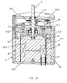
- FIG. 1A and 1B we can see a first embodiment of an interface according to the invention comprising an element 1 intended to be manipulated by a user and which will be designated later "button", this button is rotatably mounted on a shaft 2 X axis, and a force-generating device 4 resistant to the rotation of the shaft 2.
- the device 4 comprises a fluid whose characteristics can be modified by means of a magnetic field and a system for generating a magnetic field 6 received in a housing 8.
- the fluid is for example a magneto-rheological liquid 5.
- the casing 8 of cylindrical shape is formed by a side wall 8.1, a lower bottom 8.2 and an upper bottom 8.3.
- the shaft 2 passes through the upper bottom 8.3 and penetrates inside the housing 8.
- the housing 8 delimits a sealed chamber 10 confining the magnetorheological fluid 5, this chamber being subjected to a magnetic field generated by the system 6.
- the device 4 also comprises an element 12 integral in rotation with the shaft 2 and housed in the sealed chamber 10. This element is able to interact with the magnetorheological fluid 5, the rotation of the element 12 being more or less braked. by the magneto-rheological fluid 5 as a function of its apparent viscosity.
- the element 12 has the shape of a cylindrical bell of circular cross section formed of a side wall 12.1 and a bottom 12.2.
- the sealed chamber has a shape corresponding to that of the bell 12, which reduces the amount of fluid required.
- the element 12 interacting with the fluid has the shape of an inverted U.
- the bottom 12.2 is fixed on the end of the shaft 2 penetrating into the sealed chamber 10, as well as the chamber 10.
- the side wall 12.1 is made of material capable of driving a magnetic field, advantageously made of ferromagnetic material, thus the magnetic permeability of the side wall is reduced, improving the conduction of the magnetic field.
- the sealed chamber 10 is completely filled with magnetorheological fluid 5.
- the bell 12 is thus completely immersed in the magnetorheological fluid 5. More particularly, the inner and outer faces of the wall 12.1 are in contact with the magnetorheological fluid 5. But it could be expected that only the lateral wall 12.1 is immersed in the magneto-rheological fluid 5.
- the shaft 2 is supported by bearings 14.1, 14.2, sealingly insulated from the magnetorheological fluid 5.
- a sealing element 16, visible on the Figure 1B is provided between the sealed chamber 10 and the zone containing the bearings 14.1, 14.2.
- the sealing means surrounds the rotation shaft 2, which comprises an inner lip 16.1 bordering the rotation shaft 2 and providing a dynamic seal and an outer lip 16.2 in static contact with the housing. Sealing can be provided by any other type of joint, conventional or not, such as a ferrofluid held in place with a permanent magnet.
- the magnetic field generation system 6 is capable of generating a variable magnetic field so as to vary the viscosity of the magnetorheological fluid 5.
- the system 6 comprises a means 18 capable of generating a permanent magnetic field in the absence of an electrical supply, for example a permanent magnet, and means 20 capable of generating a variable magnetic field.
- the permanent magnetization means 18 will be designated by magnet permanent, but any other device offering such magnetization is not beyond the scope of the present invention.
- the magnet is, in the example shown, formed by a disk disposed inside the bell 12.
- the means for generating a variable magnetic field 20 is formed, for example by at least one coil disposed inside the bell 12 and surrounding the permanent magnet 20.
- the coil (s) has (have) a axis coincident with the longitudinal axis X.
- the system 6 comprises a magnetic circuit for guiding the magnetic field so that the field lines pass through the side wall 12.1 of the bell 12 and close inside the side wall 8.1, so that the fluid magneto-rheological 5 on either side of the side wall 12.1 is actually subject to the magnetic field.
- the permanent magnet 18 and the coil 20 are able to generate a magnetic field passing through the fluid and closing on the magnet and the coil.
- the magnetic circuit comprises a piece 22 of material capable of conducting the magnetic field forming a core, disposed inside the bell and in which the permanent magnet 18 and the coil 20 are arranged.
- the core 22 in the form of a regular cylinder has a lower portion 22.1 and an upper portion 22.2, the magnet and the coil being sandwiched between the two parts 22.1, 22.2.
- the chamber 10 is delimited, on the one hand by the outer faces of the core 22, by the outer lateral wall 8.1 and by an upper partition wall 25 through which the rotation shaft 2 passes.
- the parts 22.1, 22.2 each comprise a shoulder 23.1, 23.2 defined between a portion of larger diameter and a smaller diameter portion
- the magnet 18 is disposed between the free ends of the parts of smaller diameter
- the coil 20 is mounted around the smaller diameter portions resting on the shoulders 23.1, 23.2 by its two axial ends.
- the magnetic circuit also comprises the outer wall 8.1 of the housing 8, forming the outer wall of the sealed chamber 10.
- the magnetic circuit is received in an envelope 9, forming the outer envelope of the haptic device.
- the magnetic circuit is also formed by the side wall 12.1 of the bell 12 made of a material capable of driving a magnetic field.
- the field lines of the LCA magnet pass through the upper part 22.1 of the core, then the chamber 10 via the side wall 12.1 of the bell 12, the outer side wall 8.1 of the housing 8, the lower part 22.2 of the core 22 and close on the magnet 18.
- the LCB field lines of the coil 20 take the same magnetic circuit as the magnetic field lines LCA of the permanent magnet 18.
- This architecture according to the present invention allows a very good guidance of the magnetic field generated by the magnet 18 and the coil 20.
- the central core 22 and the wall 8.1 form a stator, while the bell 12 for rotation about the X axis forms a rotor.
- the upper part of the housing receiving the bearings 14.1, 14.2, the shaft, the bottom of the bell 12.2 are made of non-magnetic material, and the bottom bottom 8.2 of the housing to prevent the dispersion of the field lines.
- Means 28 are also provided for measuring the angular position of the bell 12 and thus of the button 1. These means are, for example, arranged between the two bearings 14.1, 14.2 and are formed by an optical encoder-type rotation sensor formed by an encoder wheel 28.1 integral in rotation with the shaft 2 and an optical fork 28.2 fixed to the housing.
- Any sensor capable of providing a logical or analog image of the position of the bell 12 is within the scope of the present invention.
- the sensor 28 is connected to a control unit (not shown) to which it transmits its measurements.
- the coil 20 is, in turn, connected to a source of electric current (not shown) controlled by the control unit to vary the intensity and direction of the current in the coil depending on the position of the bell 12, and therefore the button 1, measured by the sensor 28.
- a source of electric current not shown
- the rotation sensor 28 detects the rotation of the shaft 2 and transmits this information, as well as the measurement of the angular displacement, the angular velocity and / or the angular acceleration of the shaft 2 and, therefore of the bell 12, to the control unit.
- the control unit based on the received information generates an order to the power supply to send a current of a given intensity in a given direction according to prerecorded models or according to a communication with an external system (such as for example the GPS system in an automobile), to the coil 20.
- an external system such as for example the GPS system in an automobile
- This current may be zero if the control unit estimated that the magnetic field generated by the permanent magnet 18 is sufficient to modify the viscosity apparent fluid 5 to generate sufficient resistant forces on the bell 12.
- This current can be such that it increases the magnetic field, therefore the apparent viscosity of the fluid and, consequently, the resistant forces on the bell 12.
- This current may be such that the coil 20 generates a magnetic field in the opposite direction to that of the magnetic field produced by the permanent magnet 18, the addition of the two fields then gives a magnetic field resulting from reduced intensity, or even zero compared to that of the field produced by the permanent magnet 18 alone.
- the characteristics of the current sent into the coil may also be a function of the speed with which the knob 1 is rotated.
- the sensor may be a displacement sensor, a speed or acceleration sensor.
- the information on the movement is processed by the controller in order to define the setpoint to be sent to the power unit.
- the present invention it is possible to generate a resistive force in the absence of current.
- the permanent magnet more particularly the magnetic field that it generates, so that it modifies the apparent viscosity of the fluid so that the resistant forces on the bell immobilize the knob in rotation, it is then possible to lock the interface without consuming electricity.
- the bell 12 comprises magnets 18.1 'on the inner face and magnets 18.2' on the outer face of its side wall 12.1. These are for example tubular.
- the bell has an annular projection 30 substantially halfway up the bell, the tubular magnets 18.1 'and 18.2' being arranged above and below this projection.
- FIG. 3 another embodiment of the interface according to the invention can be seen in which the bell is doubled in order to increase the interaction surface with the fluid.
- the bell 12 has an outer lateral wall 12.1 'and an inner side wall 12.1 "concentric cylindrical integral with the bottom 12.2, and spaced apart from each other to allow the fluid to penetrate between the two walls.
- the fluid is on either side of the two concentric walls, the shear surface of the fluid is approximately doubled compared to that of the interface of the Figures 1A and 1B .
- this interface differs from that described so far in that the rotation shaft passes through the stator, more particularly the system for generating the magnetic field.
- the interface comprises a shaft 102 of longitudinal axis X to which is fixed at a first end 102.1 the button to be manipulated by the user.
- the shaft 102 is rotatably mounted in a housing 108 by means of bearings 114.1 and 114.2.
- the housing 108 forms a stator and the shaft 102 forms a rotor of which is integral in rotation a bell 112 bathed in a fluid whose viscosity properties may vary with the magnetic field.
- the position, speed or acceleration sensor 128 is, in this representation, placed at a lower end of the shaft 102.2 opposite to that to which the button (not shown) is attached. This is of the same type as previously described, it comprises, for example, a coding wheel 128.1 and an optical fork 128.2. The sensor is isolated from the fluid at the bearing 114.2.
- the magnetic circuit is similar to that of the example of Figures 1A and 1B it comprises a permanent magnet 118 in the form of a disk in the center of the core and a coil 120.
- the side wall 108.1 of the housing is made of magnetic material and the core 122.
- the permanent magnet 118 is no longer disposed in the core within the bell 112, but in the side wall 108.1 of the housing.
- the magnet has in this configuration the shape of a ring provided radially in alignment with the coil 120 and coaxial with it.
- the side wall 108.1 is made of a material capable of driving a magnetic field.
- the central core 122 is in one piece of magnetic material and has an annular groove in which the coil 120 is mounted. The coil 120 then projects radially from the radially outer periphery of the core.
- the magnet 118 is formed of two cylindrical sleeves 118.1, 118.2 arranged for one above the coil and, for the other, below the coil.
- the side wall 108.1 is made of a material capable of driving a magnetic field.
- Interfaces according to the second exemplary embodiment comprising a bell with several concentric skirts similar to that shown in FIG. figure 3 are within the scope of the present invention.
- the button is movable along the axis X.
- the shaft 102 is hollow and a rod 103 is movably mounted along the axis X inside the shaft 102.
- the rod 103 is secured to the button by a first axial end 103.1. The rod passes right through the shaft 102.
- the rod 102 and the shaft are integral in rotation, thus a rotation of the button is transmitted to the shaft via the rod 103.
- An axial displacement sensor 134 is provided to detect the axial displacement of the rod 103.
- This sensor may for example be an electric switch 134 arranged on the lower bottom 108.2 of the housing opposite the second longitudinal end 103.21 of the rod 103.
- This electric switch is connected to the control unit and can, by example serve as a validation system.
- the user can thus with one hand select a tab in a menu by moving a cursor by rotation of the button around the axis X and validate this choice by pressing the button causing the axial displacement of the rod 102 and switching the contactor 134.
- the axial displacement sensor 134 may be of any other type, for example optical or magnetic.
- the second embodiment is particularly suitable for the longitudinal displacement of the button, since the capture of its displacement is easy by using the bottom of the interface which is unused.
- a third exemplary embodiment of an interface according to the present invention can be seen, differing from the first and second exemplary embodiments in that the interface no longer includes a bell interacting in the fluid, but it is directly the central core integral in rotation with the rotation shaft which interacts with the fluid to undergo braking.
- the references are increased by 200 compared to those used for the first embodiment.
- the core 222 and the shaft 202 are integral in rotation, the core then being rotated in the fluid.
- the core 222 has an upper half portion 236 provided with an axial projection 202.1 forming the portion of the shaft 202 attached to the knob and a lower half portion 238 provided with an axial projection 202.2 of which is secured to the position sensor 228. These two half parts are integral with each other, glued or fixed by any other means.
- the permanent magnet 218 in the form of a disk is interposed between the upper half-portion 236 and the lower half-portion 238.
- the coil is embedded in the pivoting central core with the magnet 218.
- the interface according to the present invention can be seen integrated into a device 40 provided with a frame 42 on which it is mounted able to translate along Y and Z. axes, thus forming a "joystick" type command.
- the device may comprise force feedback systems in these directions Y and Z.
- the interface is mounted pivotable about the Y and Z axes according to the arrows 44, 46 respectively.
- a thermal device to simulate temperature variations, this device being for example a Peltier cell.
- this device being for example a Peltier cell.
- the user controlling a lowering of temperature would feel an impression of coldness at the level of the fingers handling the button, and in the case where it commands an elevation of the temperature, would feel an impression of warm at the level of his fingers manipulating the button.
- the information thus transmitted to the user would be more intuitive, the user could operate the button only according to how he feels. The driver can no longer perform a visual check of the screen, driving safety and comfort are therefore improved.
- force or torque sensors to measure the force or torque applied to the button, and adapt the resistance to the value of this effort or torque. For example, in the case where a large torque is applied to the button, the resistance to rotation generated by the fluid can be increased by generating a larger magnetic field.
- control unit can receive other information than the angular position of the rotation shaft, the angular acceleration or the angular speed of the button for controlling the magnetic field to be applied to the fluid, for example information relating to the pressure exerted on it, information concerning the state of the vehicle (for example, the speed, the GPS position, the indoor and outdoor temperature, etc.).
- the applied return can also be independent of external information by taking for example a time base.
- the haptic feedback does not depend on the movement made but on the time. For example, we can apply haptic jerks to a fixed frequency, whatever the speed of rotation.
Description
La présente invention se rapporte aux interfaces sensorielles offrant un retour d'effort à l'utilisateur, utilisées en particulier dans le domaine des dispositifs haptiques et dans les domaines de la réalité virtuelle et de l'automobile.The present invention relates to sensory interfaces offering a return of effort to the user, used in particular in the field of haptic devices and in the fields of virtual reality and the automobile.
Ce type d'interface haptique est par exemple utilisé dans les véhicules automobiles, formant une interface haptique embarquée assistant le conducteur automobile. Cette interface revêt la forme d'un bouton rotatif à retour d'effort, et permet à l'utilisateur d'interagir avec différents équipements ou accessoires du véhicule comme le GPS (Global Positioning System en terminologie anglaise ou Système de positionnement mondial), la radio, la climatisation...This type of haptic interface is for example used in motor vehicles, forming an onboard haptic interface assisting the automotive driver. This interface takes the form of a rotary button with force feedback, and allows the user to interact with various equipment or accessories of the vehicle such as GPS (Global Positioning System in English terminology or Global positioning system), the radio, air conditioning ...
Un tel bouton est actuellement utilisé dans les véhicules automobiles haut de gamme.Such a button is currently used in high-end motor vehicles.
Ce bouton ne possède pas de retour sensoriel en effort. En effet, la résistance ressentie par l'utilisateur pour passer d'un cran à un autre est invariable, celle-ci étant prédéfinie lors de la conception du bouton. Ainsi, l'effort en retour a une intensité constante indépendamment de la vitesse de manipulation du bouton ou du type de commande souhaité.This button has no sensory feedback in effort. Indeed, the resistance felt by the user to switch from one notch to another is invariable, the latter being predefined during the design of the button. Thus, the return force has a constant intensity regardless of the speed of manipulation of the button or the type of control desired.
La résistance appliquée par le bouton est obtenue au moyen d'un moteur à courant continu associé à des réducteurs. D'une part, ce type de générateur de résistance ne permet pas d'offrir une grande sensibilité dans l'effort ressenti par l'utilisateur. D'autre part, il est encombrant et d'une masse non négligeable. Ce qui limite son application dans des systèmes embarqués.The resistance applied by the button is obtained by means of a DC motor associated with gearboxes. On the one hand, this type of generator resistance does not allow to offer a high sensitivity in the effort felt by the user. On the other hand, it is bulky and of a significant mass. This limits its application in embedded systems.
Il existe également des interfaces haptiques, dans lesquelles le retour d'effort est obtenu en utilisant un fluide magnéto-rhéologique. En appliquant un champ magnétique à ce fluide, la viscosité apparente de celui-ci augmente et permet d'exercer un effort de freinage à un élément solidaire du bouton et baignant dans ce fluide. De telles interfaces sont décrites dans le document
C'est par conséquent un but de la présente invention d'offrir une interface haptique à retour d'effort offrant une large plage de couple résistant dans un volume réduit et dont la consommation électrique est adaptée à des applications embarquées.It is therefore an object of the present invention to provide a haptic force feedback interface offering a wide range of resistant torque in a reduced volume and whose power consumption is suitable for embedded applications.
C'est également un but de la présente invention d'offrir une interface haptique à retour d'effort formant un outil interactif, convivial, intuitif et performant.It is also an object of the present invention to provide a haptic interface with force feedback forming an interactive tool, user-friendly, intuitive and powerful.
Les buts précédemment énoncés sont atteints par une interface haptique dans laquelle la résistance au mouvement d'un bouton manipulé par un utilisateur est générée au moyen d'un fluide magnéto-rhéologique, la modification de la viscosité apparente de celui-ci étant obtenue au moyen d'un circuit magnétique comportant un ou plusieurs aimants permanents associés à un système de génération d'un champ magnétique variable.The previously stated goals are achieved by a haptic interface in which the resistance to the movement of a button manipulated by a user is generated by means of a magnetorheological fluid, the change in the apparent viscosity thereof being achieved by means a magnetic circuit comprising one or more permanent magnets associated with a system for generating a variable magnetic field.
Ainsi une résistance est appliquée en l'absence d'alimentation électrique, contrairement aux interfaces à fluide magnéto-rhéologique de l'état de la technique. Par ailleurs, il est possible d'annuler ou de renforcer le champ magnétique de l'aimant permanent par le système de génération d'un champ magnétique variable, ce qui permet d'avoir une large plage de couples résistants, adaptables à chaque type d'actionnement de l'interface, contrairement aux interfaces actuelles avec moteurs électriques, dont les efforts de retour sont figés.Thus a resistor is applied in the absence of power supply, unlike magneto-rheological fluid interfaces of the state of the art. Moreover, it is possible to cancel or strengthen the magnetic field of the permanent magnet by the system for generating a variable magnetic field, which makes it possible to have a wide range of resistant couples, adaptable to each type of magnet. operation of the interface, unlike current interfaces with electric motors, whose return efforts are frozen.
Par exemple, le champ magnétique généré par l'aimant est suffisant pour que la viscosité apparente du fluide soit telle que le mouvement du bouton soit empêché, verrouillant ainsi l'interface en l'absence de courant. L'interface est déverrouillée par application d'un champ magnétique au moyen du système de génération d'un champ magnétique variable. Ceci évite, à l'inverse des interfaces existantes, d'alimenter en permanence le système de génération de champ magnétique pour bloquer le bouton, ou de prévoir un mécanisme complexe pour verrouiller et déverrouiller le bouton, rendant l'utilisation de l'interface moins conviviale et intuitive.For example, the magnetic field generated by the magnet is sufficient so that the apparent viscosity of the fluid is such that the movement of the button is prevented, thus locking the interface in the absence of current. The interface is unlocked by applying a magnetic field by means of the system for generating a variable magnetic field. This avoids, unlike the existing interfaces, to continuously supply the magnetic field generation system to block the button, or to provide a complex mechanism for lock and unlock the button, making the use of the interface less user-friendly and intuitive.
Cette large gamme de couples résistants est par ailleurs obtenue pour une consommation électrique réduite, puisque une partie ou la totalité du champ magnétique requise pour produire l'effort résistant maximal est généré sans consommation électrique par l'aimant permanent, tout en limitant l'encombrement.This wide range of resistant couples is also obtained for reduced power consumption, since part or all of the magnetic field required to produce the maximum resistive force is generated without power consumption by the permanent magnet, while limiting congestion .
Par ailleurs, grâce à l'invention, on peut conserver une plage d'actionnement identique à celle des interfaces existantes mais dont la consommation électrique est réduite. La puissance électrique est utilisée, soit pour générer un champ magnétique qui vient s'ajouter à celui de l'aimant augmentant ainsi l'amplitude du couple ressenti, soit pour générer un champ magnétique opposé à celui de l'aimant, ce qui annule l'effet de celui-ci. Pour une puissance électrique donnée, la plage d'utilisation est doublée.Moreover, thanks to the invention, one can maintain an operating range identical to that of existing interfaces but whose power consumption is reduced. The electric power is used, either to generate a magnetic field that is added to that of the magnet thus increasing the amplitude of the torque felt, or to generate a magnetic field opposite to that of the magnet, which cancels the effect of it. For a given electric power, the usage range is doubled.
L'interface haptique développée permet donc un contrôle semi-actif du bouton en effort pour générer différentes sensations, et ce par l'intermédiaire d'un fluide magnéto-rhéologique tout en offrant un encombrement et une consommation électrique réduits. On entend par « système semi-actif », un système formant un compromis entre un système « actif » et un système « passif ». Il peut être contrôlé en temps réel mais ne peut pas injecter de l'énergie dans le système commandé. Il contrôle le retour haptique ressenti par l'utilisateur par réaction en absorbant/dissipant de l'énergie selon une loi de commande prédéfinie.The developed haptic interface thus allows a semi-active control of the button in effort to generate different sensations, and this through a magneto-rheological fluid while providing a footprint and reduced power consumption. The term "semi-active system" means a system that forms a compromise between an "active" system and a "passive" system. It can be controlled in real time but can not inject energy into the controlled system. It controls the haptic feedback felt by the user by reaction by absorbing / dissipating energy according to a predefined control law.
Dans un exemple particulièrement avantageux, l'élément d'interaction comporte un élément cylindrique à section circulaire et les moyens de génération d'un champ magnétique génèrent un champ radial par rapport à cet élément d'interaction.In a particularly advantageous example, the interaction element comprises a circular section cylindrical element and the magnetic field generating means generates a radial field with respect to this interaction element.
La présente invention a alors principalement pour objet une interface haptique comportant un élément d'interaction avec un utilisateur, un arbre de rotation duquel est solidaire en rotation ledit élément d'interaction avec l'utilisateur, un élément d'interaction avec un fluide, ledit élément d'interaction avec le fluide étant solidaire en rotation dudit arbre, ledit fluide étant du type magnéto-rhéologique, un système de génération d'un champ magnétique dans ledit fluide, et une unité de commande apte à générer des ordres audit système de génération de champ magnétique de modifier le champ magnétique, ledit système comportant des moyens de génération d'un champ magnétique variable et des moyens de génération d'un champ magnétique permanent.The present invention therefore mainly relates to a haptic interface comprising an interaction element with a user, a rotation shaft of which is integral in rotation said interaction element with the user, an interaction element with a fluid, said interaction element with the fluid being rotatably connected to said shaft, said fluid being of the magnetorheological type, a system for generating a magnetic field in said fluid, and a control unit able to generate orders to said generating system magnetic field to modify the magnetic field, said system comprising means for generating a variable magnetic field and means for generating a permanent magnetic field.
L'interface haptique selon l'invention peut comporter au moins un capteur de position angulaire, de vitesse angulaire et/ou d'accélération angulaire dudit arbre, ladite unité de commande générant les ordres en fonction des informations fournies par ledit au moins un capteur de position, de vitesse et/ou d'accélération angulaire.The haptic interface according to the invention may comprise at least one sensor for angular position, angular velocity and / or angular acceleration of said shaft, said control unit generating the commands according to the information provided by said at least one sensor. position, velocity and / or angular acceleration.
Dans un autre exemple, l'unité de commande génère des ordres au système de génération de champ magnétique à des intervalles de temps donnés fixes ou variables.In another example, the control unit generates commands to the magnetic field generation system at fixed or variable time intervals.
Ledit système de génération de champ magnétique génère avantageusement un champ magnétique radial, ce qui permet d'augmenter les efforts d'amortissement.Said magnetic field generation system advantageously generates a radial magnetic field, which makes it possible to increase the damping forces.
Les moyens de génération d'un champ magnétique permanent comportent, par exemple au moins un aimant permanent ; et les moyens de génération d'un champ magnétique variable comportent par exemple au moins une bobine électromagnétique. Ces deux éléments sont associés à un circuit magnétique fabriqué en matériaux ferromagnétique. L'axe de la bobine est avantageusement confondu avec celui de l'arbre de rotation.The means for generating a permanent magnetic field comprise, for example at least one permanent magnet; and the means for generating a variable magnetic field comprise for example at least one electromagnetic coil. These two elements are associated with a magnetic circuit made of ferromagnetic materials. The axis of the coil is advantageously coincident with that of the rotation shaft.
Par exemple, l'élément d'interaction avec le fluide comporte au moins une paroi cylindrique de révolution d'axe longitudinal et un fond, ledit fond étant fixé à l'arbre de rotation, le fluide venant en contact sur une face intérieure et une face extérieure de ladite paroi latérale. De manière avantageuse, l'élément d'interaction avec le fluide comporte plusieurs parois latérales concentriques espacées les unes des autres et solidaires du fond, ce qui augmente les efforts de cisaillement appliqués au fluide.For example, the element for interaction with the fluid comprises at least one cylindrical wall of revolution of longitudinal axis and a bottom, said bottom being fixed to the rotation shaft, the fluid coming into contact on an inner face and a outer face of said side wall. Advantageously, the fluid interaction element comprises a plurality of concentric lateral walls spaced from each other and integral with the bottom, which increases the shear forces applied to the fluid.
Dans un exemple de réalisation, les moyens de génération d'un champ magnétique permanent sont disposés à l'intérieur de l'élément d'interaction avec le fluide, immobiles par rapport à celui-ci et dans laquelle les moyens de génération d'un champ magnétique variable sont disposés à l'intérieur de l'élément d'interaction avec le fluide, immobiles par rapport à celui-ci. La bobine peut alors entourer l'aimant permanent.In an exemplary embodiment, the means for generating a permanent magnetic field are arranged inside the element for interaction with the fluid, immobile with respect thereto and in which the means for generating a variable magnetic field are arranged inside the fluid interaction element, immobile with respect to this one. The coil can then surround the permanent magnet.
Dans une variante, l'aimant permanent peut être formé d'au moins un manchon entourant la bobineAlternatively, the permanent magnet may be formed of at least one sleeve surrounding the coil
Dans une autre variante, les moyens de génération d'un champ magnétique permanent sont disposés entre deux parois latérales concentriques de l'élément d'interaction et sont immobiles par rapport à celles-ci.In another variant, the means for generating a permanent magnetic field are arranged between two concentric lateral walls of the interaction element and are immobile with respect thereto.
Dans une autre variante encore, les moyens de génération d'un champ magnétique permanent sont fixés sur l'élément d'interaction avec le fluide et les moyens de génération d'un champ magnétique variable sont immobiles par rapport à celui-ci.In yet another variant, the means for generating a permanent magnetic field are fixed on the interaction element with the fluid and the means for generating a variable magnetic field are immobile with respect thereto.
On peut également prévoir que les moyens de génération d'un champ magnétique variable sont disposés à l'intérieur de l'élément d'interaction et immobiles par rapport à celui-ci.It can also be provided that the means for generating a variable magnetic field are arranged inside the interaction element and immobile with respect thereto.
Les moyens de génération d'un champ magnétique permanent et les moyens de génération d'un champ magnétique variable peuvent également être fixés sur l'élément d'interaction avec le fluide.The means for generating a permanent magnetic field and the means for generating a variable magnetic field can also be fixed on the element for interaction with the fluid.
Dans un autre exemple de réalisation, l'arbre traverse le système de génération de champ magnétique.In another embodiment, the shaft passes through the magnetic field generation system.
Le capteur de position peut, par exemple être prévu à une extrémité longitudinale de l'arbre et comporter une partie solidaire en rotation de l'arbre et une partie immobile par rapport à l'arbre. La partie solidaire de l'arbre peut alors être une roue optique et la partie immobile une fourche optique.The position sensor may, for example be provided at a longitudinal end of the shaft and comprise a portion integral in rotation with the shaft and a stationary portion relative to the shaft. The integral part of the shaft can then be an optical wheel and the stationary part an optical fork.
De manière avantageuse, l'interface selon l'invention comporte une tige traversant de part en part l'arbre, ladite tige étant est apte à se déplacer longitudinalement et un dispositif de détection du déplacement de ladite tige.Advantageously, the interface according to the invention comprises a rod passing right through the shaft, said rod being able to move longitudinally and a device for detecting the displacement of said rod.
L'interface peut également comporter un dispositif thermique apte à modifier la température de l'élément d'interaction avec l'utilisateur, le dispositif thermique comportant au moins une cellule Pelletier et / ou un dispositif apte à faire vibrer l'élément d'interaction avec l'utilisateur.The interface may also include a thermal device capable of modifying the temperature of the interaction element with the user, the thermal device comprising at least one Pelletier cell and / or a device able to vibrate the interaction element. with the user.
La présente invention a également pour objet un ensemble haptique comportant un châssis et l'interface selon la présente invention montée sur ce châssis, ladite interface étant mobile selon l'axe de l'arbre.The present invention also relates to a haptic assembly comprising a frame and the interface according to the present invention mounted on this frame, said interface being movable along the axis of the shaft.
L'interface peut être mobile en translation selon au moins une direction orthogonale à l'axe longitudinal, et / ou est mobile en rotation autour d'au moins une direction orthogonale à l'axe longitudinal.The interface may be mobile in translation in at least one direction orthogonal to the longitudinal axis, and / or is rotatable about at least one direction orthogonal to the longitudinal axis.
L'ensemble haptique selon l'invention peut comporter des dispositifs à retour d'effort pour opposer une résistance lors d'un mouvement le long au moins d'un axe orthogonal à l'axe longitudinal ou autour de celui-ci.The haptic assembly according to the invention may comprise force feedback devices for opposing a resistance during a movement along at least one axis orthogonal to the longitudinal axis or around it.
La présente invention sera mieux comprise à l'aide de la description qui va suivre et des dessins en annexe sur lesquels :
- la
figure 1A est une vue en coupe longitudinale schématique d'un premier exemple de réalisation d'une interface haptique selon la présente invention, - la
figure 1B est une vue en coupe longitudinale d'une réalisation industrielle de l'interface de lafigure 1A , représentée en perspective, - la
figure 2 est une vue en coupe longitudinale d'une première variante de réalisation de l'interface de lafigure 1 , dans laquelle l'aimant permanent est mobile, - la
figure 3 est une demi-vue en coupe longitudinale d'une deuxième variante de réalisation de l'interface de lafigure 1 , - la
figure 4 est une demi-vue en coupe longitudinale d'un deuxième exemple de réalisation d'une interface haptique selon la présente invention, dans lequel l'arbre de rotation du bouton traverse le stator interne, - les
figures 5 à 9 sont des demi-vues en coupe longitudinale de variantes de réalisation de l'interface de lafigure 4 dans lesquelles l'arbre de rotation du bouton traverse le stator interne, - la
figure 10 est une vue en coupe longitudinale d'une interface identique à celle de lafigure 4 intégrant un déplacement longitudinal du bouton. L'arbre est creux et permet de positionner un bouton de type clic en dessous de l'arbre. - les
figures 11 et 12 sont différentes variantes de réalisation d'un troisième exemple de réalisation d'une interface selon l'invention, - les
figures 13 et 14 sont des vues en perspective d'une interface selon l'invention associée à un dispositif de translation et de rotation respectivement.
- the
Figure 1A is a schematic longitudinal sectional view of a first embodiment of a haptic interface according to the present invention, - the
Figure 1B is a longitudinal sectional view of an industrial realization of the interface of theFigure 1A , represented in perspective, - the
figure 2 is a longitudinal sectional view of a first embodiment of the interface of thefigure 1 in which the permanent magnet is movable, - the
figure 3 is a half-view in longitudinal section of a second embodiment of the interface of thefigure 1 , - the
figure 4 is a half-view in longitudinal section of a second embodiment of a haptic interface according to the present invention, in which the rotation shaft of the button passes through the internal stator, - the
Figures 5 to 9 are half-views in longitudinal section of embodiments of the interface of thefigure 4 in which the rotation shaft of the button passes through the internal stator, - the
figure 10 is a longitudinal sectional view of an interface identical to that of thefigure 4 incorporating a longitudinal displacement of the button. The shaft is hollow and allows a click button to be positioned below the shaft. - the
Figures 11 and 12 are different variants of a third embodiment of an interface according to the invention, - the
Figures 13 and 14 are perspective views of an interface according to the invention associated with a translation and rotation device respectively.
Nous allons maintenant décrire en détail des exemples de réalisation de l'interface haptique selon la présente invention.We will now describe in detail embodiments of the haptic interface according to the present invention.
L'interface haptique présente au moins un degré de rotation autour d'un axe X formant généralement un axe de révolution pour l'interface.The haptic interface has at least one degree of rotation about an axis X generally forming an axis of revolution for the interface.
Sur les
Le dispositif 4 comporte un fluide dont on peut modifier les caractéristiques au moyen d'un champ magnétique et un système de génération d'un champ magnétique 6 reçus dans un boîtier 8. Le fluide est par exemple un liquide magnéto-rhéologique 5.The device 4 comprises a fluid whose characteristics can be modified by means of a magnetic field and a system for generating a
Le boîtier 8 de forme cylindrique est formé par une paroi latérale 8.1, un fond inférieur 8.2 et un fond supérieur 8.3.The
L'arbre 2 traverse le fond supérieur 8.3 et pénètre à l'intérieur du boîtier 8.The
Le boîtier 8 délimite une chambre étanche 10 confinant le fluide magnéto-rhéologique 5, cette chambre étant soumise à un champ magnétique généré par le système 6.The
Le dispositif 4 comporte également un élément 12 solidaire en rotation de l'arbre 2 et logé dans la chambre étanche 10. Cet élément est apte à interagir avec le fluide magnéto-rhéologique 5, la rotation de l'élément 12 étant plus ou moins freinée par le fluide magnéto-rhéologique 5 en fonction de sa viscosité apparente.The device 4 also comprises an
Dans l'exemple représenté, L'élément 12 a la forme d'une cloche cylindrique de section transversale circulaire formée d'une paroi latérale 12.1 et d'un fond 12.2. La chambre étanche a une forme correspondant à celle de la cloche 12, ce qui permet de réduire la quantité de fluide nécessaire. En coupe longitudinale, l'élément 12 interagissant avec le fluide a la forme d'un U renversé.In the example shown, the
Le fond 12.2 est fixé sur l'extrémité de l'arbre 2 pénétrant dans la chambre étanche 10, ainsi que la chambre 10.The bottom 12.2 is fixed on the end of the
La paroi latérale 12.1 est en matériau apte à conduire un champ magnétique, avantageusement en matériau ferromagnétique, ainsi la perméabilité magnétique de la paroi latérale est réduite, améliorant la conduction du champ magnétique.The side wall 12.1 is made of material capable of driving a magnetic field, advantageously made of ferromagnetic material, thus the magnetic permeability of the side wall is reduced, improving the conduction of the magnetic field.
Dans l'exemple représenté, la chambre étanche 10 est complètement remplie de fluide magnéto-rhéologique 5. La cloche 12 est donc complètement immergée dans le fluide magnéto-rhéologique 5. Plus particulièrement, les faces intérieure et extérieure de la paroi 12.1 sont en contact avec le fluide magnéto-rhéologique 5. Mais on pourrait prévoir que seule la paroi latérale 12.1 soit immergée dans le fluide magnéto-rhéologique 5.In the example shown, the sealed
L'arbre 2 est supporté par des paliers 14.1, 14.2, isolés de manière étanche du fluide magnéto-rhéologique 5. Un élément d'étanchéité 16, visible sur la
Le système de génération de champ magnétique 6 est apte à générer un champ magnétique variable de manière à faire varier la viscosité du fluide magnéto-rhéologique 5.The magnetic
Selon la présente invention, le système 6 comporte un moyen 18 apte à générer un champ magnétique permanent en l'absence d'alimentation électrique, par exemple un aimant permanent, et un moyen 20 apte à générer un champ magnétique variable.According to the present invention, the
A des fins de simplicité, le moyen à magnétisation permanente 18 sera désigné par aimant permanent, mais tout autre dispositif offrant une telle magnétisation ne sort pas du cadre de la présente invention.For the sake of simplicity, the permanent magnetization means 18 will be designated by magnet permanent, but any other device offering such magnetization is not beyond the scope of the present invention.
L'aimant est, dans l'exemple représenté, formé par un disque disposé à l'intérieur de la cloche 12.The magnet is, in the example shown, formed by a disk disposed inside the
Le moyen de génération d'un champ magnétique variable 20 est formé, par exemple par au moins une bobine disposée à l'intérieur de la cloche 12 et entourant l'aimant permanent 20. La ou les bobine(s) a (ont) un axe confondu avec l'axe longitudinal X.The means for generating a variable
En outre, le système 6 comporte un circuit magnétique pour guider le champ magnétique de manière à ce que les lignes de champ traversent la paroi latérale 12.1 de la cloche 12 et se referment à l'intérieur de la paroi latérale 8.1, afin que le fluide magnéto-rhéologique 5 de part et d'autre de la paroi latérale 12.1 soit effectivement soumis au champ magnétique. De manière générale, l'aimant permanent 18 et la bobine 20 sont aptes à générer un champ magnétique traversant le fluide et se refermant sur l'aimant et la bobine.In addition, the
Le circuit magnétique comporte une pièce 22 en matériau apte à conduire le champ magnétique formant un noyau, disposée à l'intérieur de la cloche et dans laquelle sont disposés l'aimant permanent 18 et la bobine 20.The magnetic circuit comprises a
Dans l'exemple représenté, le noyau 22 en forme de cylindre régulier comporte une partie inférieure 22.1 et une partie supérieure 22.2, l'aimant et la bobine étant pris en sandwich entre les deux parties 22.1, 22.2.In the example shown, the core 22 in the form of a regular cylinder has a lower portion 22.1 and an upper portion 22.2, the magnet and the coil being sandwiched between the two parts 22.1, 22.2.
La chambre 10 est délimitée, d'une part par les faces extérieures du noyau 22, par la paroi latérale extérieure 8.1 et par une paroi de séparation supérieure 25 traversée par l'arbre de rotation 2.The
En particulier, dans l'exemple représenté, les parties 22.1, 22.2 comportent chacune un épaulement 23.1, 23.2 défini entre une partie de plus grand diamètre et une partie de plus petit diamètre, l'aimant 18 est disposé entre les extrémités libres des parties de plus petit diamètre et la bobine 20 est montée autour des parties de plus petit diamètre en appui sur les épaulements 23.1, 23.2 par ses deux extrémités axiales.In particular, in the example shown, the parts 22.1, 22.2 each comprise a shoulder 23.1, 23.2 defined between a portion of larger diameter and a smaller diameter portion, the
Le circuit magnétique comporte également la paroi extérieure 8.1 du boîtier 8, formant la paroi extérieure de la chambre étanche 10.The magnetic circuit also comprises the outer wall 8.1 of the
On pourrait prévoir que seule la partie intérieure de la paroi extérieure 8.1 soit en matériau magnétique, et non la paroi 8.1 en entier, ce qui permettrait de confiner davantage le champ magnétique.It could be expected that only the inner part of the outer wall 8.1 is magnetic material, and not the entire wall 8.1, which would further confine the magnetic field.
Le circuit magnétique est reçu dans une enveloppe 9, formant l'enveloppe extérieure du dispositif haptique.The magnetic circuit is received in an
Le circuit magnétique est également formé par la paroi latérale 12.1 de la cloche 12 réalisé en un matériau apte à conduire un champ magnétique.The magnetic circuit is also formed by the side wall 12.1 of the
Les lignes de champ de l'aimant LCA traversent la partie supérieure 22.1 du noyau, puis la chambre 10 via la paroi latérale 12.1 de la cloche 12, la paroi latérale extérieure 8.1 du boîtier 8, la partie inférieure 22.2 du noyau 22 et se referment sur l'aimant 18.The field lines of the LCA magnet pass through the upper part 22.1 of the core, then the
Les lignes de champ LCB de la bobine 20 empruntent le même circuit magnétique que les lignes de champ magnétique LCA de l'aimant permanent 18.The LCB field lines of the
Cette architecture selon la présente invention permet un très bon guidage du champ magnétique généré par l'aimant 18 et la bobine 20.This architecture according to the present invention allows a very good guidance of the magnetic field generated by the
Ainsi, il est possible en contrôlant le sens et l'intensité du courant circulant dans la bobine 20 d'amplifier ou alors de réduire, voire d'annuler le champ magnétique produit par l'aimant 18.Thus, it is possible by controlling the direction and intensity of the current flowing in the
Le noyau central 22 et la paroi 8.1 forment un stator, tandis que la cloche 12 destinée à tourner autour de l'axe X forme un rotor.The
Avantageusement, la partie supérieure du boîtier recevant les paliers 14.1, 14.2, l'arbre, le fond de la cloche 12.2 sont réalisés en matériau amagnétique, ainsi que le fond inférieur 8.2 du boîtier afin d'éviter la dispersion des lignes de champ.Advantageously, the upper part of the housing receiving the bearings 14.1, 14.2, the shaft, the bottom of the bell 12.2 are made of non-magnetic material, and the bottom bottom 8.2 of the housing to prevent the dispersion of the field lines.
Il est également prévu des moyens 28 pour mesurer la position angulaire de la cloche 12 et donc du bouton 1. Ces moyens sont, par exemple disposés entre les deux paliers 14.1, 14.2 et sont formés par un capteur de rotation de type codeur optique, formé par une roue codeuse 28.1 solidaire en rotation de l'arbre 2 et d'une fourche optique 28.2 fixée sur le boîtier.Means 28 are also provided for measuring the angular position of the
Tout capteur apte à fournir une image logique ou analogique de la position de la cloche 12 entre dans le cadre de la présente invention.Any sensor capable of providing a logical or analog image of the position of the
Le capteur 28 est raccordé à une unité de commande (non représentée) à laquelle il transmet ses mesures.The
La bobine 20 est, quant à elle, reliée à une source de courant électrique (non représentée) commandée par l'unité de commande afin de faire varier l'intensité et le sens du courant dans la bobine en fonction de la position de la cloche 12, et donc du bouton 1, mesurée par le capteur 28.The
Nous allons maintenant expliquer le fonctionnement de cette interface haptique selon la présente invention.We will now explain the operation of this haptic interface according to the present invention.
Lorsque l'utilisateur manipule le bouton 1, en particulier lorsqu'il le fait pivoter dans un sens ou dans l'autre autour de l'axe X, le capteur de rotation 28 détecte la rotation de l'arbre 2 et transmet cette information, ainsi que la mesure du déplacement angulaire, de la vitesse angulaire et/ou de l'accélération angulaire de l'arbre 2 et, donc de la cloche 12, à l'unité de commande.When the user manipulates the
L'unité de commande en fonction des informations reçues génère un ordre à l'alimentation électrique d'envoyer un courant d'une intensité donnée dans un sens donné en fonction de modèles préenregistrés ou en fonction d'une communication avec un système extérieur (comme par exemple le système GPS dans une automobile), à la bobine 20.The control unit based on the received information generates an order to the power supply to send a current of a given intensity in a given direction according to prerecorded models or according to a communication with an external system (such as for example the GPS system in an automobile), to the
Ce courant peut être nul si l'unité de commande estimé que le champ magnétique généré par l'aimant permanent 18 suffit à modifier la viscosité apparente du fluide 5 pour générer des efforts résistants suffisants sur la cloche 12.This current may be zero if the control unit estimated that the magnetic field generated by the
Ce courant peut être tel qu'il augmente le champ magnétique, donc la viscosité apparente du fluide et, par conséquent les efforts résistants sur la cloche 12.This current can be such that it increases the magnetic field, therefore the apparent viscosity of the fluid and, consequently, the resistant forces on the
Ce courant peut être tel que la bobine 20 génère un champ magnétique de sens opposé à celui du champ magnétique produit par l'aimant permanent 18, l'addition des deux champs donne alors un champ magnétique résultant d'intensité réduite, voire nulle par rapport à celle du champ produit par l'aimant permanent 18 seul.This current may be such that the
Les caractéristiques du courant envoyé dans la bobine peuvent également être fonction de la vitesse avec laquelle le bouton 1 est tourné. Le capteur peut être un capteur de déplacement, un capteur de vitesse ou d'accélération. Les informations sur le mouvement sont traitées par l'organe de commande afin de définir la consigne à envoyer à l'organe de puissance.The characteristics of the current sent into the coil may also be a function of the speed with which the
Grâce à la présente invention, il est possible de générer un effort résistant en l'absence de courant. Ainsi, en choisissant l'aimant permanent, plus particulièrement le champ magnétique qu'il génère, de telle sorte que celui-ci modifie la viscosité apparente du fluide pour que les efforts résistants sur la cloche immobilisent le bouton en rotation, il est alors possible de verrouiller l'interface sans consommer d'électricité.With the present invention, it is possible to generate a resistive force in the absence of current. Thus, by choosing the permanent magnet, more particularly the magnetic field that it generates, so that it modifies the apparent viscosity of the fluid so that the resistant forces on the bell immobilize the knob in rotation, it is then possible to lock the interface without consuming electricity.
En outre, en couplant un aimant permanent et une bobine, on atteint des valeurs de champ magnétique importantes, et donc des couples résistants appliqués à la cloche élevés tout en limitant l'encombrement de l'interface et la puissance électrique nécessaire.In addition, by coupling a permanent magnet and a coil, field values are reached magnetic magnets, and therefore resistant torques applied to the high bell while limiting the size of the interface and the necessary electrical power.
Dans le cas de systèmes existants n'utilisant qu'une bobine, l'encombrement est bien plus conséquent pour obtenir les mêmes valeurs de couple résistant.In the case of existing systems using only one coil, the bulk is much larger to obtain the same values of resistant torque.
Sur la
Plus particulièrement, la cloche 12 comporte des aimants 18.1' sur la face intérieure et des aimants 18.2' sur la face extérieure de sa paroi latérale 12.1. Ceux-ci sont par exemple tubulaires. Dans l'exemple représenté, la cloche comporte une saillie annulaire 30 sensiblement à mi-hauteur de la cloche, les aimants tubulaires 18.1' et 18.2' étant disposés au dessus et au dessous de cette saillie.More particularly, the
On pourrait prévoir de réaliser deux manchons en matériau magnétique permanent s'étendant d'une extrémité à l'autre de la cloche.One could provide to make two sleeves permanent magnetic material extending from one end to the other of the bell.
Sur la
Dans l'exemple représenté, la cloche 12 comporte une paroi latérale extérieure 12.1' et une paroi latérale intérieure 12.1" cylindriques concentriques solidaires du fond 12.2, et espacées l'une de l'autre pour permettre au fluide de pénétrer entre les deux parois.In the example shown, the
Le fluide se trouve de part et d'autre des deux parois concentriques, la surface de cisaillement du fluide est approximativement doublée par rapport à celle de l'interface des
Dans l'exemple représenté, on prévoit de disposer l'aimant permanent 18" entre les deux parois 12.1' et 12.1", celui-ci est identique à celui de la
On peut également prévoir d'utiliser une cloche dont la jupe est formée de plusieurs parois concentriques dans une structure identique à celle des
Sur la
Les références utilisées pour la description de cet exemple de réalisation seront augmentées de 100 par rapport à celle utilisés pour la description des
L'interface comporte un arbre 102 d'axe longitudinal X à laquelle est fixée à une première extrémité 102.1 le bouton destiné à être manipulé par l'utilisateur.The interface comprises a
L'arbre 102 est monté en rotation dans un boîtier 108 au moyen de paliers 114.1 et 114.2.The
Le boîtier 108 forme un stator et l'arbre 102 forme un rotor duquel est solidaire en rotation une cloche 112 baignant dans un fluide dont les propriétés de viscosité peuvent varier avec le champ magnétique.The
Par rapport à l'exemple des
Le capteur de position, de vitesse ou d'accélération 128 est, dans cette représentation, placé à une extrémité inférieure de l'arbre 102.2 opposée à celle à laquelle est fixé le bouton (non représenté). Celui-ci est du même type que décrit précédemment, il comporte, par exemple, une roue codeuse 128.1 et une fourche optique 128.2. Le capteur est isolé du fluide au niveau du palier 114.2.The position, speed or
Le circuit magnétique est similaire à celui de l'exemple des
La paroi latérale 108.1 du boîtier est réalisée en matériau magnétique ainsi que le noyau 122.The side wall 108.1 of the housing is made of magnetic material and the
Le fonctionnement de cette interface est identique à celui des
Sur la
Sur la
Sur la
Dans l'exemple représenté, le noyau central 122 est d'une seule pièce en matériau magnétique et comporte une rainure annulaire dans laquelle est montée la bobine 120. La bobine 120 fait alors saillie radialement de la périphérie radialement extérieure du noyau.In the example shown, the
L'aimant 118, quant à lui, est formé de deux manchons cylindriques 118.1, 118.2 disposés pour l'un au dessus de la bobine et, pour l'autre, au dessous de la bobine.The
On peut prévoir de disposer l'aimant permanent 118 dans la paroi latérale 108.1 du boîtier.It can be provided to dispose the
D'ailleurs, sur la
La paroi latérale 108.1 est réalisée en un matériau apte à conduire un champ magnétique.The side wall 108.1 is made of a material capable of driving a magnetic field.
Sur la
Des interfaces selon le deuxième exemple de réalisation comportant une cloche à plusieurs jupes concentriques similaire à celle représentée sur la
Sur la
La tige 102 et l'arbre sont solidaires en rotation, ainsi une rotation du bouton est transmise à l'arbre par l'intermédiaire de la tige 103.The
Un capteur de déplacement axial 134 est prévu pour détecter le déplacement axial de la tige 103. Ce capteur peut par exemple être un contacteur électrique 134 disposé sur le fond inférieur 108.2 du boîtier en regard de la deuxième extrémité longitudinale 103.21 de la tige 103. Lorsque la tige 103 est déplacée axialement vers le bas selon la flèche 135, elle actionne le contacteur 134. Ce contacteur électrique est relié à l'unité de commande et peut, par exemple servir de système de validation.An
L'utilisateur peut ainsi d'une seule main sélectionner un onglet dans un menu en déplaçant un curseur par rotation du bouton autour de l'axe X et valider ce choix en enfonçant le bouton provoquant le déplacement axial de la tige 102 et la commutation du contacteur 134.The user can thus with one hand select a tab in a menu by moving a cursor by rotation of the button around the axis X and validate this choice by pressing the button causing the axial displacement of the
Le capteur de déplacement axial 134 peut être de tout autre type, par exemple optique ou magnétique.The
Dans l'exemple représenté, seul la tige 103 se déplace le long de l'axe X. Cependant, on peut prévoir que toute l'interface formée par le boîtier et le bouton se déplace selon l'axe X.In the example shown, only the
Ce degré de liberté supplémentaire peut bien entendu être appliqué à tous les exemples de réalisation.This additional degree of freedom can of course be applied to all the exemplary embodiments.
Le deuxième exemple de réalisation est particulièrement adapté au déplacement longitudinal du bouton, puisque la capture de son déplacement est aisée en utilisant le fond inférieur de l'interface qui est inutilisé.The second embodiment is particularly suitable for the longitudinal displacement of the button, since the capture of its displacement is easy by using the bottom of the interface which is unused.
Sur les
Les références sont augmentées de 200 par rapport à celles utilisées pour le premier exemple de réalisation.The references are increased by 200 compared to those used for the first embodiment.
Comme on peut le voir sur la
Le noyau 222 comporte une demi partie supérieure 236 munie d'une saillie axiale 202.1 formant la partie de l'arbre 202 fixée au bouton et une demi partie inférieure 238 munie d'une saillie axiale 202.2 de laquelle est solidaire le capteur de position 228. Ces deux demi parties sont solidaires l'une de l'autre, collées ou fixées par tout autre moyen.The
L'aimant permanent 218 sous forme de disque est interposé entre la demi partie supérieure 236 et la demi partie inférieure 238. La bobine est embarquée dans le noyau central pivotant avec l'aimant 218.The
Sur la
Il est bien entendu que les nombres de bobines et/ou d'aimants mentionnés dans la description ci-dessus ne sont en aucun cas limitatifs et peuvent varier suivant les configurations. Les formes, notamment celles des aimants, ne sont également en aucun cas limitatives.It is understood that the numbers of coils and / or magnets mentioned in the description above are in no way limiting and can vary according to the configurations. The shapes, especially those of magnets, are also in no way limiting.
Sur la
Sur la
Ces intégrations peuvent, par exemple permettre d'ajouter des fonctionnalités à laquelle le bouton est déjà couplé.These integrations can, for example to add features to which the button is already coupled.
On peut également prévoir d'intégrer dans le bouton un dispositif thermique pour simuler des variations de température, ce dispositif étant par exemple une cellule Peltier. Ainsi, dans le cas de la commande du système de chauffage-climatisation, par exemple, l'utilisateur commandant un abaissement de température ressentirait une impression de froid au niveau des doigts manipulant le bouton, et dans le cas où il commande une élévation de la température, ressentirait une impression de chaud au niveau de ses doigts manipulant le bouton. L'information ainsi transmise à l'utilisateur serait plus intuitive, l'utilisateur pourrait actionner le bouton uniquement en fonction de ce qu'il ressent. Le conducteur peut alors ne plus effectuer un contrôle visuel de l'écran, la sécurité de conduite et son confort en sont donc améliorés.It is also possible to integrate in the button a thermal device to simulate temperature variations, this device being for example a Peltier cell. Thus, in the case of the control of the heating-air conditioning system, for example, the user controlling a lowering of temperature would feel an impression of coldness at the level of the fingers handling the button, and in the case where it commands an elevation of the temperature, would feel an impression of warm at the level of his fingers manipulating the button. The information thus transmitted to the user would be more intuitive, the user could operate the button only according to how he feels. The driver can no longer perform a visual check of the screen, driving safety and comfort are therefore improved.
On peut également prévoir un dispositif générant des vibrations dans le bouton, permettant d'enrichir l'information rendue à l'utilisateur. Par exemple, si l'utilisateur a un appel téléphonique alors qu'il est en train de naviguer dans un menu, il peut être averti par une vibration.One can also provide a device generating vibrations in the button, to enrich the information returned to the user. For example, if the user has a phone call while he is navigating a menu, he can be warned by a vibration.
On peut également prévoir de mettre en oeuvre des capteurs d'effort ou de couple pour mesurer l'effort ou le couple appliqué au bouton, et adapter la résistance à la valeur de cet effort ou de couple. Par exemple, dans le cas où un couple important est appliqué au bouton, la résistance à la rotation générée par le fluide peut être augmentée en générant un champ magnétique plus important.It is also possible to use force or torque sensors to measure the force or torque applied to the button, and adapt the resistance to the value of this effort or torque. For example, in the case where a large torque is applied to the button, the resistance to rotation generated by the fluid can be increased by generating a larger magnetic field.
Il est bien entendu que l'unité de commande peut recevoir d'autres informations que la position angulaire de l'arbre de rotation, l'accélération angulaire ou la vitesse angulaire du bouton pour commander le champ magnétique à appliquer au fluide, par exemple des informations portant sur, la pression exercée sur celui-ci, des informations concernant l'état du véhicule (par exemple, la vitesse, la position GPS, la température intérieure et extérieure, etc....).It is understood that the control unit can receive other information than the angular position of the rotation shaft, the angular acceleration or the angular speed of the button for controlling the magnetic field to be applied to the fluid, for example information relating to the pressure exerted on it, information concerning the state of the vehicle (for example, the speed, the GPS position, the indoor and outdoor temperature, etc.).
Le retour appliqué peut également être indépendant d'informations extérieures en prenant par exemple une base temporelle. Le retour haptique ne dépend pas du mouvement effectué mais du temps. On peut par exemple appliquer des à-coups haptiques à une fréquence fixe et ce, quelle que soit la vitesse de rotation.The applied return can also be independent of external information by taking for example a time base. The haptic feedback does not depend on the movement made but on the time. For example, we can apply haptic jerks to a fixed frequency, whatever the speed of rotation.
On peut également prévoir de coupler des informations extérieures et une base temporelle pour commander le système de génération de champ magnétique.It is also possible to couple external information and a time base for controlling the magnetic field generation system.
Claims (20)
- Haptic interface comprising an element that interacts with a user, a rotation shaft (2, 102, 202) with a longitudinal axis (X) to which said user interaction element (1) is fixed in rotation, an element that interacts with a fluid (12, 112, 212), said fluid interaction element (12, 112, 212) being fixed in rotation to said shaft (2, 102, 202), said fluid being of magneto-rheological type, a system (6) for generating a magnetic field in said fluid designed to modify the viscosity of the fluid, a control unit capable of generating orders to said magnetic field generation system (6) so as to modify the magnetic field, the interaction element (12, 112, 212), the fluid and the system for generating a magnetic field being in a housing (8), characterized in that said system for generating a magnetic field comprises means of generating a variable magnetic field (20, 120, 220,32) and means of generating a permanent magnetic field, said means of generating a permanent magnetic field (18, 18", 118, 218) being arranged in said housing (8) such that they provoke an increase of the viscosity of the fluid and a permanent force resisting to the fluid interaction element.
- Haptic interface according to claim 1, the means of generating a permanent magnetic field (18, 18", 118, 218) being arranged inside the housing and/or in a housing sidewall (8).
- Haptic interface according to either claim 1 or 2, comprising at least one angular position, angular velocity and/or angular acceleration sensor (28, 128, 228) of said shaft (2, 102, 202), said control unit generating orders as a function of information provided by said at least one angular position, velocity and/or acceleration sensor (28, 128, 228).
- Haptic interface according to one of claims 1 to 3, in which said control unit generates orders to the magnetic field generation system at given fixed or variable time intervals.
- Haptic interface according to one of claims 1 to 4, in which said system (6) for generating a permanent magnetic field (18, 18", 118, 218) generates a radial magnetic field.
- Haptic interface according to one of claims 1 to 5, in which the means of generating a permanent magnetic field (18, 18", 118, 218) comprise at least one permanent magnet.
- Haptic interface according to one of claims 1 to 6, in which the means of generating a variable magnetic field (20, 120, 220) comprise at least an electromagnetic coil.
- Haptic interface according to one of claims 1 to 7, in which the fluid interaction element (12, 112) comprises at least one cylindrical wall (12.1, 112.1) of revolution with a longitudinal axis (X) and a head made from a non-magnetic material (12.2), said head (12.2) being fixed to the rotation shaft (2, 102, 202), the fluid coming into contact on an inner face and an outer face of said sidewall (12.1, 112.1).
- Haptic interface according to claim 8, in which the fluid interaction element (12) comprises several concentric sidewalls (12.1', 12.1") at a spacing from each other and fixed to the head made of non-magnetic material (12.2).
- Haptic interface according to one of claims 1 to 9, in which the means of generating a permanent magnetic field are arranged inside the fluid interaction element (12), immobile relative to the housing and in which the means of generating a variable magnetic field (20) are arranged inside the fluid interaction element (12), immobile relative to the housing.
- Haptic interface according to claim 9, in which the means of generating a permanent magnetic field (18") are arranged between two concentric sidewalls (12.1', 12.1") of the bell (12) and are immobile relative to the housing.
- Haptic interface according to one of claims 1 to 9, in which the means of generating a permanent magnetic field are fixed on the fluid interaction element (12, 112, 212) and the means of generating a variable magnetic field (20, 120, 220) are immobile relative to the housing.
- Haptic interface according to claim 12, in which the means of generating a variable magnetic field (20, 32) are arranged inside the interaction element that is immobile relative to the housing.
- Haptic interface according to one of claims 1 to 9, in which the means of generating a permanent magnetic field and the means of generating a variable magnetic filed are fixed onto the fluid interaction element.
- Haptic interface according to one of claims 1 to 14, in which the shaft (102, 202) passes through the magnetic field generation and said interface comprising a rod (103) passing through the shaft (102) from one side to the other, said rod being capable to move longitudinally and a device (134) for detecting displacement of said rod (103) being provided.
- Haptic interface according to one of claims 1 to 15, in which the position, velocity or angular acceleration sensor (28, 128, 228) is provided at one shaft longitudinal end and comprises a part fixed in rotation with the shaft and a part immobile relative to the shaft, for example the part fixed on the shaft (2, 102, 202) is an optical wheel and the immobile part is an optical fork.
- Haptic interface according to one of the previous claims, comprising a device capable of vibrating the user interaction element and/or a thermal device capable of modifying the temperature of the user interaction element, the thermal device comprisinf for example at least one Peltier cell.
- Haptic assembly comprising a frame and the interface according to one of the previous claims mounted on this frame (42), said interface being free to move along the axis (X) of the shaft.
- Haptic assembly according to claim 18, in which the interface is free to move in translation along at least one direction (Y, Z) orthogonal to the longitudinal axis (X) and/or is free to move in rotation about at least one direction (Y, Z) orthogonal to the longitudinal axis (X).
- Haptic assembly according to claim 19, comprising force feedback devices to oppose a resistance during a movement along at least one axis orthogonal to or about the longitudinal axis.
Applications Claiming Priority (2)
| Application Number | Priority Date | Filing Date | Title |
|---|---|---|---|
| FR0852899A FR2930655B1 (en) | 2008-04-29 | 2008-04-29 | EFFORT RETURN INTERFACE WITH ENHANCED SENSATION |
| PCT/EP2009/055039 WO2009133056A1 (en) | 2008-04-29 | 2009-04-27 | Force-feedback interface with improved sensations |
Publications (2)
| Publication Number | Publication Date |
|---|---|
| EP2274660A1 EP2274660A1 (en) | 2011-01-19 |
| EP2274660B1 true EP2274660B1 (en) | 2014-11-12 |
Family
ID=39971127
Family Applications (1)
| Application Number | Title | Priority Date | Filing Date |
|---|---|---|---|
| EP09738100.8A Active EP2274660B1 (en) | 2008-04-29 | 2009-04-27 | Force-feedback interface with improved sensations |
Country Status (5)
| Country | Link |
|---|---|
| US (1) | US8878657B2 (en) |
| EP (1) | EP2274660B1 (en) |
| JP (2) | JP5523444B2 (en) |
| FR (1) | FR2930655B1 (en) |
| WO (1) | WO2009133056A1 (en) |
Families Citing this family (96)
| Publication number | Priority date | Publication date | Assignee | Title |
|---|---|---|---|---|
| DE102009007209B4 (en) * | 2009-02-03 | 2014-07-03 | Fraunhofer-Gesellschaft zur Förderung der angewandten Forschung e.V. | Switchable magnetorheological torque or power transmission device, its use and magnetorheological torque or power transmission method |
| FR2952985B1 (en) * | 2009-11-25 | 2012-01-13 | Commissariat Energie Atomique | SEMI-ACTIVE DEVICE IN TRANSLATION AND ROTATION |
| US10007290B2 (en) * | 2010-09-15 | 2018-06-26 | Inventus Engineering Gmbh | Haptic operating device with a rotating element and method |
| EP2710277B1 (en) * | 2011-05-17 | 2017-03-01 | BeijingWest Industries Co. Ltd. | Magneto-rheological damping assembly |
| CN102562923A (en) * | 2012-02-08 | 2012-07-11 | 谢宁 | Rotary magnetorheological damper with magnetorheological elastomer |
| CN102879174B (en) * | 2012-08-30 | 2015-08-26 | 江苏大学 | Magnetic flow liquid yield stress method of testing and device thereof |
| JP5995366B2 (en) * | 2013-02-15 | 2016-09-21 | アルプス電気株式会社 | Force imparted planar slide input device |
| CN105228535B (en) | 2013-03-29 | 2018-12-11 | 皇家飞利浦有限公司 | With the force feedback chucking device based on magnetorheological actuator |
| US9753436B2 (en) | 2013-06-11 | 2017-09-05 | Apple Inc. | Rotary input mechanism for an electronic device |
| CN109634447B (en) | 2013-08-09 | 2022-04-19 | 苹果公司 | Tactile switch for electronic devices |
| JP2015047525A (en) * | 2013-08-30 | 2015-03-16 | アルプス電気株式会社 | Vibration generator |
| FR3010550B1 (en) * | 2013-09-09 | 2019-11-01 | Dav | METHOD AND INTERFACE OF HAPTICALLY RETURN CONTROL FOR MOTOR VEHICLE |
| US10048802B2 (en) | 2014-02-12 | 2018-08-14 | Apple Inc. | Rejection of false turns of rotary inputs for electronic devices |
| CN104134313B (en) * | 2014-03-09 | 2017-03-08 | 浙江师范大学 | A kind of selectivity alarm based on magnetic flow liquid |
| US9435101B2 (en) * | 2014-04-24 | 2016-09-06 | Topcon Positioning Systems, Inc. | Semi-automatic control of a joystick for dozer blade control |
| CN104141730B (en) * | 2014-06-30 | 2016-08-24 | 北京交通大学 | A kind of magnetic fixing type magnetic fluid damper |
| US10190891B1 (en) | 2014-07-16 | 2019-01-29 | Apple Inc. | Optical encoder for detecting rotational and axial movement |
| FR3024559B1 (en) * | 2014-07-31 | 2017-12-22 | Dav | HAP-RETURN CONTROL INTERFACE FOR MOTOR VEHICLE |
| FR3024561B1 (en) * | 2014-07-31 | 2017-12-22 | Dav | HAP-RETURN CONTROL INTERFACE FOR MOTOR VEHICLE |
| WO2016016589A1 (en) * | 2014-07-31 | 2016-02-04 | Dav | Haptic-feedback control method and interface for a motor vehicle |
| FR3024560B1 (en) * | 2014-07-31 | 2016-10-28 | Dav | METHOD AND INTERFACE OF HAPTICALLY RETURN CONTROL FOR MOTOR VEHICLE |
| US10599101B2 (en) | 2014-09-02 | 2020-03-24 | Apple Inc. | Wearable electronic device |
| FR3026551B1 (en) * | 2014-09-29 | 2017-12-22 | Commissariat Energie Atomique | HAPTIC INTERFACE PROVIDING CONTROL OF IMPROVED HAPTIC RESOURCE |
| FR3026552B1 (en) * | 2014-09-29 | 2017-12-22 | Commissariat Energie Atomique | DEVICE FOR HAPTIC INTERFACE WITH REDUCED VACUUM TORQUE |
| FR3026553B1 (en) * | 2014-09-29 | 2021-03-19 | Commissariat Energie Atomique | HAPTICAL INTERFACE TAKING INTO ACCOUNT THE USER'S ACTION INTENT |
| FR3028329B1 (en) * | 2014-11-06 | 2018-01-05 | Dav | METHOD AND INTERFACE OF HAPTICALLY RETURN CONTROL FOR MOTOR VEHICLE |
| FR3029308B1 (en) * | 2014-12-02 | 2017-12-22 | Commissariat Energie Atomique | HAPTIC INTERFACE HAPPENED IMPROVED, IN PARTICULAR IN THE REPRODUCTION OF A STROKE |
| CN105990066B (en) * | 2015-01-28 | 2018-08-10 | 西门子公司 | Dc circuit breaker, direct current interruption equipment and control method |
| US10145711B2 (en) | 2015-03-05 | 2018-12-04 | Apple Inc. | Optical encoder with direction-dependent optical properties having an optically anisotropic region to produce a first and a second light distribution |
| JP6452502B2 (en) * | 2015-03-07 | 2019-01-16 | 株式会社栗本鐵工所 | Magnetorheological fluid device |
| EP3251139B1 (en) | 2015-03-08 | 2021-04-28 | Apple Inc. | Compressible seal for rotatable and translatable input mechanisms |
| US10018966B2 (en) | 2015-04-24 | 2018-07-10 | Apple Inc. | Cover member for an input mechanism of an electronic device |
| JP6573434B2 (en) * | 2015-05-22 | 2019-09-11 | 国立大学法人金沢大学 | Haptic interface |
| JP6585172B2 (en) * | 2015-06-22 | 2019-10-02 | アルプスアルパイン株式会社 | Input device and control method of input device |
| KR101680265B1 (en) * | 2015-08-24 | 2016-11-28 | 한국기술교육대학교 산학협력단 | Tactile Generating Apparatus |
| US9732817B2 (en) | 2015-10-13 | 2017-08-15 | Goodrich Corporation | Axial engagement-controlled variable damper systems and methods |
| US9765850B2 (en) * | 2015-10-13 | 2017-09-19 | Goodrich Corporation | Saturation-controlled variable damper systems and methods |
| CN205159175U (en) * | 2015-10-21 | 2016-04-13 | 厦门优胜卫厨科技有限公司 | Knob switching device |
| KR102594718B1 (en) * | 2015-11-20 | 2023-10-26 | 하만인터내셔날인더스트리스인코포레이티드 | Dynamic reconfigurable display knob |
| FR3044729B1 (en) * | 2015-12-07 | 2018-01-05 | Commissariat A L'energie Atomique Et Aux Energies Alternatives | MAGNETO-RHEOLOGICAL BRAKE OR DAMPING DEVICE |
| WO2017145857A1 (en) | 2016-02-26 | 2017-08-31 | アルプス電気株式会社 | Operation device |
| US9891651B2 (en) | 2016-02-27 | 2018-02-13 | Apple Inc. | Rotatable input mechanism having adjustable output |
| KR102231316B1 (en) | 2016-03-07 | 2021-03-23 | 알프스 알파인 가부시키가이샤 | Fe-based alloy composition, soft magnetic material, magnetic member, electrical/electronic related parts and devices |
| ES2579161B2 (en) * | 2016-03-08 | 2017-03-28 | Universidad De Las Palmas De Gran Canaria | Aloe Vera hybrid nanofibers |
| JP6544804B2 (en) * | 2016-03-22 | 2019-07-17 | アルプスアルパイン株式会社 | Input device |
| US10551798B1 (en) | 2016-05-17 | 2020-02-04 | Apple Inc. | Rotatable crown for an electronic device |
| EP3477418B1 (en) * | 2016-06-27 | 2021-06-16 | Alps Alpine Co., Ltd. | Operation device and method for controlling same |
| US10061399B2 (en) | 2016-07-15 | 2018-08-28 | Apple Inc. | Capacitive gap sensor ring for an input device |
| US10019097B2 (en) | 2016-07-25 | 2018-07-10 | Apple Inc. | Force-detecting input structure |
| WO2018051545A1 (en) | 2016-09-16 | 2018-03-22 | アルプス電気株式会社 | Operation feel imparting type input device |
| FR3056315B1 (en) * | 2016-09-21 | 2018-09-28 | Commissariat A L'energie Atomique Et Aux Energies Alternatives | HAPTIC INTERFACE WITH AT LEAST TWO DEGREES OF FREEDOM HAVING IMPROVED HAPTIC RESOURCE |
| FR3056316B1 (en) * | 2016-09-21 | 2018-09-28 | Commissariat A L'energie Atomique Et Aux Energies Alternatives | HAPTIC INTERFACE HAS KINESTHESIC AND VIBROTACTILE STIMULATIONS |
| JP2020016909A (en) * | 2016-11-21 | 2020-01-30 | アルプスアルパイン株式会社 | Input device |
| JP6634166B2 (en) * | 2016-12-21 | 2020-01-22 | アルプスアルパイン株式会社 | Operation device |
| JPWO2018143021A1 (en) * | 2017-02-06 | 2019-07-04 | アルプスアルパイン株式会社 | Tactile display device |
| JP6793314B2 (en) * | 2017-02-21 | 2020-12-02 | パナソニックIpマネジメント株式会社 | Input device |
| WO2018193917A1 (en) * | 2017-04-21 | 2018-10-25 | アルプス電気株式会社 | Rotary-type operation device, method for controlling same, and program |
| DE102017111031A1 (en) * | 2017-05-20 | 2018-11-22 | Inventus Engineering Gmbh | Haptic control device |
| US10664074B2 (en) | 2017-06-19 | 2020-05-26 | Apple Inc. | Contact-sensitive crown for an electronic watch |
| DE102017210436A1 (en) * | 2017-06-21 | 2018-12-27 | Zf Friedrichshafen Ag | Rotation control means |
| DE102017210442A1 (en) * | 2017-06-21 | 2018-12-27 | Zf Friedrichshafen Ag | Dehsteuervorrichtung |
| DE102017210439A1 (en) * | 2017-06-21 | 2018-12-27 | Zf Friedrichshafen Ag | Rotation control device |
| DE102017210438A1 (en) | 2017-06-21 | 2018-12-27 | Zf Friedrichshafen Ag | Rotary control device for a vehicle |
| DE102017210437A1 (en) * | 2017-06-21 | 2018-12-27 | Zf Friedrichshafen Ag | Rotary control device for a vehicle |
| US10330195B2 (en) * | 2017-06-27 | 2019-06-25 | Panasonic Corporation | Input device |
| US10962935B1 (en) | 2017-07-18 | 2021-03-30 | Apple Inc. | Tri-axis force sensor |
| US10592008B1 (en) | 2017-09-05 | 2020-03-17 | Apple Inc. | Mouse having a shape-changing enclosure |
| WO2019131453A1 (en) * | 2017-12-28 | 2019-07-04 | アルプスアルパイン株式会社 | Input device |
| JP2019144659A (en) * | 2018-02-16 | 2019-08-29 | パイオニア株式会社 | Input apparatus |
| JP7161853B2 (en) * | 2018-03-05 | 2022-10-27 | 株式会社栗本鐵工所 | joystick device |
| JP2021099896A (en) * | 2018-03-30 | 2021-07-01 | パナソニックIpマネジメント株式会社 | Input device and input system |
| US11360440B2 (en) | 2018-06-25 | 2022-06-14 | Apple Inc. | Crown for an electronic watch |
| US11561515B2 (en) | 2018-08-02 | 2023-01-24 | Apple Inc. | Crown for an electronic watch |
| CN209560398U (en) | 2018-08-24 | 2019-10-29 | 苹果公司 | Electronic watch |
| US11181863B2 (en) | 2018-08-24 | 2021-11-23 | Apple Inc. | Conductive cap for watch crown |
| CN112543900A (en) * | 2018-08-30 | 2021-03-23 | 阿尔卑斯阿尔派株式会社 | Operation device and control method for operation device |
| US11194298B2 (en) | 2018-08-30 | 2021-12-07 | Apple Inc. | Crown assembly for an electronic watch |
| CN209625187U (en) | 2018-08-30 | 2019-11-12 | 苹果公司 | Electronic watch and electronic equipment |
| DE102018222237A1 (en) | 2018-12-19 | 2020-06-25 | Zf Friedrichshafen Ag | Rotary control device |
| DE102018222235A1 (en) | 2018-12-19 | 2020-06-25 | Zf Friedrichshafen Ag | Rotary control device |
| US11194299B1 (en) | 2019-02-12 | 2021-12-07 | Apple Inc. | Variable frictional feedback device for a digital crown of an electronic watch |
| DE102019213958A1 (en) | 2019-09-12 | 2021-03-18 | Zf Friedrichshafen Ag | Rotation control device for steering |
| DE102019213959A1 (en) | 2019-09-12 | 2021-03-18 | Zf Friedrichshafen Ag | Rotation control device for steering |
| DE102019135760A1 (en) * | 2019-12-18 | 2021-06-24 | Inventus Engineering Gmbh | Magnetorheological braking device |
| FR3106532A1 (en) * | 2020-01-24 | 2021-07-30 | Psa Automobiles Sa | Motor vehicle dashboard rotary control knob |
| US11550268B2 (en) | 2020-06-02 | 2023-01-10 | Apple Inc. | Switch module for electronic crown assembly |
| US11635786B2 (en) | 2020-06-11 | 2023-04-25 | Apple Inc. | Electronic optical sensing device |
| US11650670B2 (en) * | 2020-11-30 | 2023-05-16 | Logitech Europe S.A. | Combining electropermanent magnets and magnetorheological fluid to modify an operation of an input device |
| DE102021111965A1 (en) * | 2021-05-06 | 2022-11-10 | Inventus Engineering Gmbh | Magnetorheological braking device, in particular operating device |
| US11747919B1 (en) * | 2021-05-14 | 2023-09-05 | Apple Inc. | Multi-input for rotating and translating crown modules |
| CN114385001B (en) * | 2021-12-06 | 2023-11-24 | 歌尔股份有限公司 | Haptic feedback assembly and force feedback device thereof |
| DE102022115076A1 (en) | 2022-06-15 | 2023-12-21 | Signata GmbH | Adjusting device for a vehicle and method for operating an adjusting device |
| DE102022115073A1 (en) | 2022-06-15 | 2023-12-21 | Signata GmbH | Adjusting device for a vehicle and method for operating an adjusting device |
| DE102022115074A1 (en) | 2022-06-15 | 2023-12-21 | Signata GmbH | Adjusting device for a vehicle and method for operating an adjusting device |
| DE102022115774A1 (en) | 2022-06-24 | 2024-01-04 | Signata GmbH | Operating arrangement with a control knob mounted in a housing |
| JP2024010554A (en) * | 2022-07-12 | 2024-01-24 | オムロン株式会社 | Operation device and wheel mouse |
Family Cites Families (25)
| Publication number | Priority date | Publication date | Assignee | Title |
|---|---|---|---|---|
| JP3039997B2 (en) * | 1991-02-15 | 2000-05-08 | 株式会社ブリヂストン | Electro-rheological fluid application device, electro-rheological fluid application vibration control device, and electro-rheological fluid application fixing device |
| US5509888A (en) * | 1994-07-26 | 1996-04-23 | Conceptek Corporation | Controller valve device and method |
| DE4433056C2 (en) * | 1994-09-16 | 1998-01-29 | Mannesmann Sachs Ag | Vibration dampers for motor vehicles |
| JP4014014B2 (en) * | 1997-08-12 | 2007-11-28 | 富士重工業株式会社 | In-vehicle central control device |
| US5878997A (en) * | 1997-09-10 | 1999-03-09 | Lucent Technologies Inc. | Compact low-inductance magnetorheological damper |
| US6186290B1 (en) * | 1997-10-29 | 2001-02-13 | Lord Corporation | Magnetorheological brake with integrated flywheel |
| JP2000081917A (en) * | 1998-09-04 | 2000-03-21 | Sony Corp | Device for indicating sense of power touch and sense of temperature |
| US6339419B1 (en) * | 1998-11-10 | 2002-01-15 | Lord Corporation | Magnetically-controllable, semi-active haptic interface system and apparatus |
| US6373465B2 (en) * | 1998-11-10 | 2002-04-16 | Lord Corporation | Magnetically-controllable, semi-active haptic interface system and apparatus |
| US6240779B1 (en) * | 1999-07-06 | 2001-06-05 | Kung Ching-Hu | Gravity-type horizontal shift sensing apparatus |
| US6527661B2 (en) * | 2000-05-12 | 2003-03-04 | Auburn Gear, Inc. | Limited slip differential having magnetorheological fluid brake |
| DE10029191A1 (en) | 2000-06-19 | 2001-12-20 | Philips Corp Intellectual Pty | Haptic control element e.g. for vehicle instrument panel, has gap between electronically controled rotary knob, magnetic circuit filled with magnetorheological liquid, and coil for producing variable braking effect on knob |
| JP3920563B2 (en) * | 2000-12-22 | 2007-05-30 | アルプス電気株式会社 | Manual input device |
| US6854573B2 (en) * | 2001-10-25 | 2005-02-15 | Lord Corporation | Brake with field responsive material |
| US6612166B2 (en) * | 2001-12-13 | 2003-09-02 | Rosemount Aerospace Inc. | Variable viscosity damper for vane type angle of attack sensor |
| JP3846415B2 (en) * | 2002-11-28 | 2006-11-15 | トヨタ自動車株式会社 | Vehicle steering device |
| DE102004041690A1 (en) * | 2003-08-27 | 2005-03-24 | Marquardt Gmbh | Cursor or joystick type electrical switch for installation in a motor vehicle has an activation organ with movement means that interact with a magneto- or electro-rheological assembly to generate a haptic response |
| DE102005003593A1 (en) * | 2004-01-29 | 2005-09-15 | Preh Gmbh | Operating element for motor vehicle has element that achieves spring action arranged between rotary knob and brake element so that relative movement between rotary knob and brake element can be achieved |
| JP2007538301A (en) * | 2004-01-29 | 2007-12-27 | プレー・ゲゼルシャフト・ミト・ベシュレンクテル・ハフツング | Programmable rotational torque supply device using spring parts |
| US7382357B2 (en) * | 2005-04-25 | 2008-06-03 | Avago Technologies Ecbu Ip Pte Ltd | User interface incorporating emulated hard keys |
| US7401834B2 (en) * | 2005-07-13 | 2008-07-22 | Gm Global Technology Operations, Inc. | Child seat anchor assembly and methods of use |
| JP2007087671A (en) * | 2005-09-20 | 2007-04-05 | Omron Corp | Switching device |
| DE102005060933B3 (en) * | 2005-12-20 | 2007-06-06 | Lisa Dräxlmaier GmbH | Gear selector lever e.g. shift-by-wire lever, for e.g. commercial vehicle, has haptic unit formed by pressure unit, gear wheels, motor and/or damper and producing force path of lever, where unit is fixedly arranged with respect to housing |
| DE102006012807A1 (en) * | 2006-03-21 | 2007-09-27 | Behr-Hella Thermocontrol Gmbh | Control unit for use in motor vehicle, has capacitive contact sensor comprising contact areas, which come in contact with body part of operator for operating control unit, where contact areas are heated or cooled in regions by peltier units |
| FR2902538A1 (en) * | 2006-06-14 | 2007-12-21 | Commissariat Energie Atomique | TOUCH OR HAPTIC SIMULATION DEVICE AND MUSICAL KEYBOARD COMPRISING AT LEAST ONE SUCH SIMULATION DEVICE |
-
2008
- 2008-04-29 FR FR0852899A patent/FR2930655B1/en active Active
-
2009
- 2009-04-27 WO PCT/EP2009/055039 patent/WO2009133056A1/en active Application Filing
- 2009-04-27 EP EP09738100.8A patent/EP2274660B1/en active Active
- 2009-04-27 JP JP2011506671A patent/JP5523444B2/en not_active Expired - Fee Related
- 2009-04-27 US US12/990,083 patent/US8878657B2/en active Active
-
2014
- 2014-04-07 JP JP2014078711A patent/JP5916783B2/en not_active Expired - Fee Related
Also Published As
| Publication number | Publication date |
|---|---|
| EP2274660A1 (en) | 2011-01-19 |
| JP2011519098A (en) | 2011-06-30 |
| FR2930655A1 (en) | 2009-10-30 |
| US8878657B2 (en) | 2014-11-04 |
| JP5523444B2 (en) | 2014-06-18 |
| FR2930655B1 (en) | 2013-02-08 |
| JP2014149857A (en) | 2014-08-21 |
| JP5916783B2 (en) | 2016-05-11 |
| US20110181405A1 (en) | 2011-07-28 |
| WO2009133056A1 (en) | 2009-11-05 |
Similar Documents
| Publication | Publication Date | Title |
|---|---|---|
| EP2274660B1 (en) | Force-feedback interface with improved sensations | |
| EP2269128B1 (en) | Haptic interface having braking force increased | |
| EP3201725B1 (en) | Haptic interface with improved haptic rendering | |
| EP4154089A1 (en) | Control interface with haptic feedback | |
| FR3010546A1 (en) | HAPTIC RETURN CONTROL INTERFACE | |
| EP3360026A1 (en) | Hybrid haptic interface with improved haptic feedback | |
| EP2277095A2 (en) | Electromagnetic actuator and corresponding control device with haptic feedback | |
| WO2016050718A1 (en) | Haptic interface providing improved control of the haptic sensation | |
| EP3201933B1 (en) | Device for haptic interface with reduced no-load torque | |
| EP2201263B1 (en) | Damping device capable of providing an increased stiffness | |
| EP2244168B1 (en) | Control device with haptic feedback and corresponding actuator | |
| EP3198370B1 (en) | Haptic-feedback control interface for a motor vehicle | |
| WO2016016589A1 (en) | Haptic-feedback control method and interface for a motor vehicle | |
| FR3084940A1 (en) | HAPTIC RETURN CONTROL INTERFACE | |
| FR3010550B1 (en) | METHOD AND INTERFACE OF HAPTICALLY RETURN CONTROL FOR MOTOR VEHICLE | |
| FR3026501A1 (en) | METHOD AND INTERFACE OF HAPTICALLY RETURN CONTROL FOR MOTOR VEHICLE | |
| WO2016071634A1 (en) | Haptic feedback control method and interface for a motor vehicle | |
| WO2023084123A1 (en) | Device for detecting relative position with circuit breaker | |
| WO2016016521A1 (en) | Motor vehicle haptic feedback control method and interface | |
| FR3128940A1 (en) | Control stick force application device, stick, method, program and aircraft |
Legal Events
| Date | Code | Title | Description |
|---|---|---|---|
| PUAI | Public reference made under article 153(3) epc to a published international application that has entered the european phase |
Free format text: ORIGINAL CODE: 0009012 |
|
| 17P | Request for examination filed |
Effective date: 20101104 |
|
| AK | Designated contracting states |
Kind code of ref document: A1 Designated state(s): AT BE BG CH CY CZ DE DK EE ES FI FR GB GR HR HU IE IS IT LI LT LU LV MC MK MT NL NO PL PT RO SE SI SK TR |
|
| AX | Request for extension of the european patent |
Extension state: AL BA RS |
|
| RIN1 | Information on inventor provided before grant (corrected) |
Inventor name: LOZADA, JOSE Inventor name: ROSELIER, SAMUEL Inventor name: PERIQUET, FLORIAN Inventor name: HAFEZ, MOUSTAPHA |
|
| RIN1 | Information on inventor provided before grant (corrected) |
Inventor name: LOZADA, JOSE Inventor name: ROSELIER, SAMUEL Inventor name: PERIQUET, FLORIAN Inventor name: HAFEZ, MOUSTAPHA |
|
| DAX | Request for extension of the european patent (deleted) | ||
| 17Q | First examination report despatched |
Effective date: 20130711 |
|
| GRAJ | Information related to disapproval of communication of intention to grant by the applicant or resumption of examination proceedings by the epo deleted |
Free format text: ORIGINAL CODE: EPIDOSDIGR1 |
|
| RIC1 | Information provided on ipc code assigned before grant |
Ipc: F16F 9/53 20060101ALI20131204BHEP Ipc: G05G 1/08 20060101AFI20131204BHEP Ipc: G05G 5/03 20080401ALI20131204BHEP |
|
| GRAP | Despatch of communication of intention to grant a patent |
Free format text: ORIGINAL CODE: EPIDOSNIGR1 |
|
| INTG | Intention to grant announced |
Effective date: 20140115 |
|
| RAP1 | Party data changed (applicant data changed or rights of an application transferred) |
Owner name: COMMISSARIAT A L'ENERGIE ATOMIQUE ET AUX ENERGIES |
|
| GRAP | Despatch of communication of intention to grant a patent |
Free format text: ORIGINAL CODE: EPIDOSNIGR1 |
|
| INTG | Intention to grant announced |
Effective date: 20140606 |
|
| GRAS | Grant fee paid |
Free format text: ORIGINAL CODE: EPIDOSNIGR3 |
|
| GRAA | (expected) grant |
Free format text: ORIGINAL CODE: 0009210 |
|
| AK | Designated contracting states |
Kind code of ref document: B1 Designated state(s): AT BE BG CH CY CZ DE DK EE ES FI FR GB GR HR HU IE IS IT LI LT LU LV MC MK MT NL NO PL PT RO SE SI SK TR |
|
| REG | Reference to a national code |
Ref country code: GB Ref legal event code: FG4D Free format text: NOT ENGLISH |
|
| REG | Reference to a national code |
Ref country code: CH Ref legal event code: EP |
|
| REG | Reference to a national code |
Ref country code: AT Ref legal event code: REF Ref document number: 696112 Country of ref document: AT Kind code of ref document: T Effective date: 20141115 |
|
| REG | Reference to a national code |
Ref country code: IE Ref legal event code: FG4D Free format text: LANGUAGE OF EP DOCUMENT: FRENCH |
|
| REG | Reference to a national code |
Ref country code: DE Ref legal event code: R096 Ref document number: 602009027706 Country of ref document: DE Effective date: 20141224 |
|
| REG | Reference to a national code |
Ref country code: NL Ref legal event code: VDEP Effective date: 20141112 |
|
| REG | Reference to a national code |
Ref country code: AT Ref legal event code: MK05 Ref document number: 696112 Country of ref document: AT Kind code of ref document: T Effective date: 20141112 |
|
| PG25 | Lapsed in a contracting state [announced via postgrant information from national office to epo] |
Ref country code: IS Free format text: LAPSE BECAUSE OF FAILURE TO SUBMIT A TRANSLATION OF THE DESCRIPTION OR TO PAY THE FEE WITHIN THE PRESCRIBED TIME-LIMIT Effective date: 20150312 Ref country code: FI Free format text: LAPSE BECAUSE OF FAILURE TO SUBMIT A TRANSLATION OF THE DESCRIPTION OR TO PAY THE FEE WITHIN THE PRESCRIBED TIME-LIMIT Effective date: 20141112 Ref country code: ES Free format text: LAPSE BECAUSE OF FAILURE TO SUBMIT A TRANSLATION OF THE DESCRIPTION OR TO PAY THE FEE WITHIN THE PRESCRIBED TIME-LIMIT Effective date: 20141112 Ref country code: PT Free format text: LAPSE BECAUSE OF FAILURE TO SUBMIT A TRANSLATION OF THE DESCRIPTION OR TO PAY THE FEE WITHIN THE PRESCRIBED TIME-LIMIT Effective date: 20150312 Ref country code: NO Free format text: LAPSE BECAUSE OF FAILURE TO SUBMIT A TRANSLATION OF THE DESCRIPTION OR TO PAY THE FEE WITHIN THE PRESCRIBED TIME-LIMIT Effective date: 20150212 Ref country code: NL Free format text: LAPSE BECAUSE OF FAILURE TO SUBMIT A TRANSLATION OF THE DESCRIPTION OR TO PAY THE FEE WITHIN THE PRESCRIBED TIME-LIMIT Effective date: 20141112 Ref country code: LT Free format text: LAPSE BECAUSE OF FAILURE TO SUBMIT A TRANSLATION OF THE DESCRIPTION OR TO PAY THE FEE WITHIN THE PRESCRIBED TIME-LIMIT Effective date: 20141112 |
|
| PG25 | Lapsed in a contracting state [announced via postgrant information from national office to epo] |
Ref country code: LV Free format text: LAPSE BECAUSE OF FAILURE TO SUBMIT A TRANSLATION OF THE DESCRIPTION OR TO PAY THE FEE WITHIN THE PRESCRIBED TIME-LIMIT Effective date: 20141112 Ref country code: HR Free format text: LAPSE BECAUSE OF FAILURE TO SUBMIT A TRANSLATION OF THE DESCRIPTION OR TO PAY THE FEE WITHIN THE PRESCRIBED TIME-LIMIT Effective date: 20141112 Ref country code: GR Free format text: LAPSE BECAUSE OF FAILURE TO SUBMIT A TRANSLATION OF THE DESCRIPTION OR TO PAY THE FEE WITHIN THE PRESCRIBED TIME-LIMIT Effective date: 20150213 Ref country code: CY Free format text: LAPSE BECAUSE OF FAILURE TO SUBMIT A TRANSLATION OF THE DESCRIPTION OR TO PAY THE FEE WITHIN THE PRESCRIBED TIME-LIMIT Effective date: 20141112 Ref country code: AT Free format text: LAPSE BECAUSE OF FAILURE TO SUBMIT A TRANSLATION OF THE DESCRIPTION OR TO PAY THE FEE WITHIN THE PRESCRIBED TIME-LIMIT Effective date: 20141112 Ref country code: PL Free format text: LAPSE BECAUSE OF FAILURE TO SUBMIT A TRANSLATION OF THE DESCRIPTION OR TO PAY THE FEE WITHIN THE PRESCRIBED TIME-LIMIT Effective date: 20141112 Ref country code: SE Free format text: LAPSE BECAUSE OF FAILURE TO SUBMIT A TRANSLATION OF THE DESCRIPTION OR TO PAY THE FEE WITHIN THE PRESCRIBED TIME-LIMIT Effective date: 20141112 |
|
| PG25 | Lapsed in a contracting state [announced via postgrant information from national office to epo] |
Ref country code: CZ Free format text: LAPSE BECAUSE OF FAILURE TO SUBMIT A TRANSLATION OF THE DESCRIPTION OR TO PAY THE FEE WITHIN THE PRESCRIBED TIME-LIMIT Effective date: 20141112 Ref country code: EE Free format text: LAPSE BECAUSE OF FAILURE TO SUBMIT A TRANSLATION OF THE DESCRIPTION OR TO PAY THE FEE WITHIN THE PRESCRIBED TIME-LIMIT Effective date: 20141112 Ref country code: SK Free format text: LAPSE BECAUSE OF FAILURE TO SUBMIT A TRANSLATION OF THE DESCRIPTION OR TO PAY THE FEE WITHIN THE PRESCRIBED TIME-LIMIT Effective date: 20141112 Ref country code: DK Free format text: LAPSE BECAUSE OF FAILURE TO SUBMIT A TRANSLATION OF THE DESCRIPTION OR TO PAY THE FEE WITHIN THE PRESCRIBED TIME-LIMIT Effective date: 20141112 Ref country code: RO Free format text: LAPSE BECAUSE OF FAILURE TO SUBMIT A TRANSLATION OF THE DESCRIPTION OR TO PAY THE FEE WITHIN THE PRESCRIBED TIME-LIMIT Effective date: 20141112 |
|
| REG | Reference to a national code |
Ref country code: DE Ref legal event code: R097 Ref document number: 602009027706 Country of ref document: DE |
|
| PLBE | No opposition filed within time limit |
Free format text: ORIGINAL CODE: 0009261 |
|
| STAA | Information on the status of an ep patent application or granted ep patent |
Free format text: STATUS: NO OPPOSITION FILED WITHIN TIME LIMIT |
|
| 26N | No opposition filed |
Effective date: 20150813 |
|
| PG25 | Lapsed in a contracting state [announced via postgrant information from national office to epo] |
Ref country code: MC Free format text: LAPSE BECAUSE OF FAILURE TO SUBMIT A TRANSLATION OF THE DESCRIPTION OR TO PAY THE FEE WITHIN THE PRESCRIBED TIME-LIMIT Effective date: 20141112 Ref country code: LU Free format text: LAPSE BECAUSE OF FAILURE TO SUBMIT A TRANSLATION OF THE DESCRIPTION OR TO PAY THE FEE WITHIN THE PRESCRIBED TIME-LIMIT Effective date: 20150427 |
|
| REG | Reference to a national code |
Ref country code: CH Ref legal event code: PL |
|
| PG25 | Lapsed in a contracting state [announced via postgrant information from national office to epo] |
Ref country code: IT Free format text: LAPSE BECAUSE OF FAILURE TO SUBMIT A TRANSLATION OF THE DESCRIPTION OR TO PAY THE FEE WITHIN THE PRESCRIBED TIME-LIMIT Effective date: 20141112 |
|
| REG | Reference to a national code |
Ref country code: IE Ref legal event code: MM4A |
|
| PG25 | Lapsed in a contracting state [announced via postgrant information from national office to epo] |
Ref country code: CH Free format text: LAPSE BECAUSE OF NON-PAYMENT OF DUE FEES Effective date: 20150430 Ref country code: LI Free format text: LAPSE BECAUSE OF NON-PAYMENT OF DUE FEES Effective date: 20150430 |
|
| PG25 | Lapsed in a contracting state [announced via postgrant information from national office to epo] |
Ref country code: SI Free format text: LAPSE BECAUSE OF FAILURE TO SUBMIT A TRANSLATION OF THE DESCRIPTION OR TO PAY THE FEE WITHIN THE PRESCRIBED TIME-LIMIT Effective date: 20141112 |
|
| REG | Reference to a national code |
Ref country code: FR Ref legal event code: PLFP Year of fee payment: 8 |
|
| PG25 | Lapsed in a contracting state [announced via postgrant information from national office to epo] |
Ref country code: IE Free format text: LAPSE BECAUSE OF NON-PAYMENT OF DUE FEES Effective date: 20150427 |
|
| PG25 | Lapsed in a contracting state [announced via postgrant information from national office to epo] |
Ref country code: MT Free format text: LAPSE BECAUSE OF FAILURE TO SUBMIT A TRANSLATION OF THE DESCRIPTION OR TO PAY THE FEE WITHIN THE PRESCRIBED TIME-LIMIT Effective date: 20141112 |
|
| REG | Reference to a national code |
Ref country code: FR Ref legal event code: PLFP Year of fee payment: 9 |
|
| PG25 | Lapsed in a contracting state [announced via postgrant information from national office to epo] |
Ref country code: BG Free format text: LAPSE BECAUSE OF FAILURE TO SUBMIT A TRANSLATION OF THE DESCRIPTION OR TO PAY THE FEE WITHIN THE PRESCRIBED TIME-LIMIT Effective date: 20141112 Ref country code: HU Free format text: LAPSE BECAUSE OF FAILURE TO SUBMIT A TRANSLATION OF THE DESCRIPTION OR TO PAY THE FEE WITHIN THE PRESCRIBED TIME-LIMIT; INVALID AB INITIO Effective date: 20090427 |
|
| PG25 | Lapsed in a contracting state [announced via postgrant information from national office to epo] |
Ref country code: BE Free format text: LAPSE BECAUSE OF NON-PAYMENT OF DUE FEES Effective date: 20150430 |
|
| PG25 | Lapsed in a contracting state [announced via postgrant information from national office to epo] |
Ref country code: TR Free format text: LAPSE BECAUSE OF FAILURE TO SUBMIT A TRANSLATION OF THE DESCRIPTION OR TO PAY THE FEE WITHIN THE PRESCRIBED TIME-LIMIT Effective date: 20141112 |
|
| REG | Reference to a national code |
Ref country code: FR Ref legal event code: PLFP Year of fee payment: 10 |
|
| PG25 | Lapsed in a contracting state [announced via postgrant information from national office to epo] |
Ref country code: MK Free format text: LAPSE BECAUSE OF FAILURE TO SUBMIT A TRANSLATION OF THE DESCRIPTION OR TO PAY THE FEE WITHIN THE PRESCRIBED TIME-LIMIT Effective date: 20141112 |
|
| RIC2 | Information provided on ipc code assigned after grant |
Ipc: F16F 9/53 20060101ALI20131204BHEP Ipc: G05G 1/08 20060101AFI20131204BHEP Ipc: G05G 5/03 20080401ALI20131204BHEP |
|
| PGFP | Annual fee paid to national office [announced via postgrant information from national office to epo] |
Ref country code: GB Payment date: 20210415 Year of fee payment: 13 |
|
| GBPC | Gb: european patent ceased through non-payment of renewal fee |
Effective date: 20220427 |
|
| PG25 | Lapsed in a contracting state [announced via postgrant information from national office to epo] |
Ref country code: GB Free format text: LAPSE BECAUSE OF NON-PAYMENT OF DUE FEES Effective date: 20220427 |
|
| PGFP | Annual fee paid to national office [announced via postgrant information from national office to epo] |
Ref country code: FR Payment date: 20230424 Year of fee payment: 15 Ref country code: DE Payment date: 20230418 Year of fee payment: 15 |