WO2018193917A1 - Rotary-type operation device, method for controlling same, and program - Google Patents
Rotary-type operation device, method for controlling same, and program Download PDFInfo
- Publication number
- WO2018193917A1 WO2018193917A1 PCT/JP2018/015101 JP2018015101W WO2018193917A1 WO 2018193917 A1 WO2018193917 A1 WO 2018193917A1 JP 2018015101 W JP2018015101 W JP 2018015101W WO 2018193917 A1 WO2018193917 A1 WO 2018193917A1
- Authority
- WO
- WIPO (PCT)
- Prior art keywords
- torque
- control signal
- control
- operation member
- rotation angle
- Prior art date
Links
Images


Classifications
-
- G—PHYSICS
- G06—COMPUTING; CALCULATING OR COUNTING
- G06F—ELECTRIC DIGITAL DATA PROCESSING
- G06F3/00—Input arrangements for transferring data to be processed into a form capable of being handled by the computer; Output arrangements for transferring data from processing unit to output unit, e.g. interface arrangements
- G06F3/01—Input arrangements or combined input and output arrangements for interaction between user and computer
- G06F3/016—Input arrangements with force or tactile feedback as computer generated output to the user
-
- G—PHYSICS
- G08—SIGNALLING
- G08B—SIGNALLING OR CALLING SYSTEMS; ORDER TELEGRAPHS; ALARM SYSTEMS
- G08B6/00—Tactile signalling systems, e.g. personal calling systems
-
- F—MECHANICAL ENGINEERING; LIGHTING; HEATING; WEAPONS; BLASTING
- F16—ENGINEERING ELEMENTS AND UNITS; GENERAL MEASURES FOR PRODUCING AND MAINTAINING EFFECTIVE FUNCTIONING OF MACHINES OR INSTALLATIONS; THERMAL INSULATION IN GENERAL
- F16D—COUPLINGS FOR TRANSMITTING ROTATION; CLUTCHES; BRAKES
- F16D57/00—Liquid-resistance brakes; Brakes using the internal friction of fluids or fluid-like media, e.g. powders
- F16D57/002—Liquid-resistance brakes; Brakes using the internal friction of fluids or fluid-like media, e.g. powders comprising a medium with electrically or magnetically controlled internal friction, e.g. electrorheological fluid, magnetic powder
-
- G—PHYSICS
- G05—CONTROLLING; REGULATING
- G05G—CONTROL DEVICES OR SYSTEMS INSOFAR AS CHARACTERISED BY MECHANICAL FEATURES ONLY
- G05G1/00—Controlling members, e.g. knobs or handles; Assemblies or arrangements thereof; Indicating position of controlling members
- G05G1/08—Controlling members for hand actuation by rotary movement, e.g. hand wheels
-
- G—PHYSICS
- G05—CONTROLLING; REGULATING
- G05G—CONTROL DEVICES OR SYSTEMS INSOFAR AS CHARACTERISED BY MECHANICAL FEATURES ONLY
- G05G5/00—Means for preventing, limiting or returning the movements of parts of a control mechanism, e.g. locking controlling member
- G05G5/03—Means for enhancing the operator's awareness of arrival of the controlling member at a command or datum position; Providing feel, e.g. means for creating a counterforce
-
- G—PHYSICS
- G06—COMPUTING; CALCULATING OR COUNTING
- G06F—ELECTRIC DIGITAL DATA PROCESSING
- G06F3/00—Input arrangements for transferring data to be processed into a form capable of being handled by the computer; Output arrangements for transferring data from processing unit to output unit, e.g. interface arrangements
- G06F3/01—Input arrangements or combined input and output arrangements for interaction between user and computer
- G06F3/03—Arrangements for converting the position or the displacement of a member into a coded form
- G06F3/033—Pointing devices displaced or positioned by the user, e.g. mice, trackballs, pens or joysticks; Accessories therefor
- G06F3/0362—Pointing devices displaced or positioned by the user, e.g. mice, trackballs, pens or joysticks; Accessories therefor with detection of 1D translations or rotations of an operating part of the device, e.g. scroll wheels, sliders, knobs, rollers or belts
-
- G—PHYSICS
- G06—COMPUTING; CALCULATING OR COUNTING
- G06F—ELECTRIC DIGITAL DATA PROCESSING
- G06F3/00—Input arrangements for transferring data to be processed into a form capable of being handled by the computer; Output arrangements for transferring data from processing unit to output unit, e.g. interface arrangements
- G06F3/01—Input arrangements or combined input and output arrangements for interaction between user and computer
- G06F3/03—Arrangements for converting the position or the displacement of a member into a coded form
- G06F3/033—Pointing devices displaced or positioned by the user, e.g. mice, trackballs, pens or joysticks; Accessories therefor
- G06F3/038—Control and interface arrangements therefor, e.g. drivers or device-embedded control circuitry
-
- H—ELECTRICITY
- H02—GENERATION; CONVERSION OR DISTRIBUTION OF ELECTRIC POWER
- H02P—CONTROL OR REGULATION OF ELECTRIC MOTORS, ELECTRIC GENERATORS OR DYNAMO-ELECTRIC CONVERTERS; CONTROLLING TRANSFORMERS, REACTORS OR CHOKE COILS
- H02P6/00—Arrangements for controlling synchronous motors or other dynamo-electric motors using electronic commutation dependent on the rotor position; Electronic commutators therefor
- H02P6/08—Arrangements for controlling the speed or torque of a single motor
-
- H—ELECTRICITY
- H02—GENERATION; CONVERSION OR DISTRIBUTION OF ELECTRIC POWER
- H02P—CONTROL OR REGULATION OF ELECTRIC MOTORS, ELECTRIC GENERATORS OR DYNAMO-ELECTRIC CONVERTERS; CONTROLLING TRANSFORMERS, REACTORS OR CHOKE COILS
- H02P6/00—Arrangements for controlling synchronous motors or other dynamo-electric motors using electronic commutation dependent on the rotor position; Electronic commutators therefor
- H02P6/24—Arrangements for stopping
-
- G—PHYSICS
- G05—CONTROLLING; REGULATING
- G05G—CONTROL DEVICES OR SYSTEMS INSOFAR AS CHARACTERISED BY MECHANICAL FEATURES ONLY
- G05G2505/00—Means for preventing, limiting or returning the movements of parts of a control mechanism, e.g. locking controlling member
-
- H—ELECTRICITY
- H01—ELECTRIC ELEMENTS
- H01H—ELECTRIC SWITCHES; RELAYS; SELECTORS; EMERGENCY PROTECTIVE DEVICES
- H01H19/00—Switches operated by an operating part which is rotatable about a longitudinal axis thereof and which is acted upon directly by a solid body external to the switch, e.g. by a hand
- H01H19/02—Details
- H01H19/03—Means for limiting the angle of rotation of the operating part
Definitions
- the present invention relates to a rotary operation device capable of controlling an operation feeling associated with a rotation operation, a control method thereof, and a program.
- a force sense imparting input device described in Patent Document 1 below includes an operation member that is rotated by an operator, an electric actuator that applies torque to the operation member, and a rotation angle detection that detects the rotation angle of the operation member. Means, rotational speed detection means for detecting the angular velocity of the operating member, and control means for controlling the electric actuator in accordance with the rotational angle and angular velocity of the operating member.
- This force sense input device can generate an operation feeling similar to a click mechanism by controlling the torque applied to the operation member from the electric actuator according to the rotation angle and rotation speed of the operation member accompanying the rotation operation. it can.
- the operational feeling of the rotary operation device is based on the senses obtained by actual operations such as the sense of load associated with the rotational operation and the sense of impact transmitted to the finger. If the difference from the feeling to do becomes large, the operator may feel uncomfortable.
- the inertia torque of the operation member changes according to the inertia moment and angular acceleration of the operating member. Even if a constant torque is applied to the operating member using an electric actuator or the like, the constant torque that does not change in accordance with the angular acceleration is different from the inertia torque, and thus the above-mentioned uncomfortable feeling of the operator cannot be eliminated.
- the present invention has been made in view of such circumstances, and a purpose thereof is a rotary operation device capable of reducing a sense of incongruity of an operation feeling caused by a discrepancy between an appearance texture of an operation member and a load felt in an actual operation, and It is to provide a control method and a program.
- a rotary operation device includes an operation member that can rotate in response to a rotation operation, and a control torque for rotationally driving or braking the operation member in accordance with an input control signal.
- a generated torque generating unit a rotation angle sensor that detects a rotation angle of the operation member, a control signal generation unit that generates the control signal according to a detected value of the rotation angle in the rotation angle sensor, and the rotation angle
- the control signal is corrected so that a correction torque for making the apparent moment of inertia of the operating member with respect to the rotation operation different from the original moment of inertia is added to the control torque based on a time change of the detected value of A first correction unit.
- the correction torque for making the apparent moment of inertia of the operation member with respect to the rotation operation different from the original moment of inertia is added to the control torque, whereby the appearance of the operation member is apparent. It becomes possible to adapt the moment of inertia to the appearance of the operating member. Therefore, the uncomfortable feeling of operation due to the discrepancy between the appearance texture of the operation member and the load felt in the actual operation is reduced.
- the first correction unit calculates an angular acceleration of the operation member based on the detected value of the rotation angle, and a first inertia torque estimated based on the inertia moment of the operation member and the angular acceleration.
- the control signal may be corrected so that a correction torque corresponding to the control torque is added to the control torque.
- the correction torque according to the first inertia torque estimated based on the moment of inertia of the operation member and the angular acceleration is added to the control torque, whereby the operation with respect to the rotation operation is performed.
- the apparent moment of inertia of the member changes with respect to the original virtual moment.
- the rotary operation device includes a torque sensor that detects a torsion torque acting between a portion to which the operation torque of the rotation operation is applied and a portion to which the control torque is applied in the operation member;
- the control signal is corrected so that an error torque, which is a difference between the control torque estimated based on the detected value of the torsion torque and the detected value of the rotation angle, and the control torque corresponding to the control signal becomes small.
- a second correction unit is a second correction unit.
- the error torque which is the difference between the control torque estimated based on the detected value of the torsion torque and the detected value of the rotation angle, and the control torque corresponding to the control signal is reduced. .
- the apparent moment of inertia of the operation member is set with high accuracy.
- the second correction unit calculates an angular acceleration of the operation member based on the detected value of the rotation angle, and the moment of inertia and the angular acceleration of the rotating member on the torque generation unit side as viewed from the torque sensor.
- the second inertia torque is calculated based on the difference between the control torque estimated based on the detected value of the torsion torque and the second inertia torque, and the control torque corresponding to the control signal.
- the control signal may be corrected so that the error torque becomes small.
- the second inertia torque is calculated based on the moment of inertia of the rotating member on the torque generating unit side as viewed from the torque sensor and the angular acceleration.
- the error torque is a difference between the control torque estimated based on the detected value of the torsion torque and the second inertia torque, and the control torque corresponding to the control signal.
- the torque generation unit includes a drive unit that generates a driving torque for rotationally driving the operation member according to the input first control signal, and the operation member according to the input second control signal. And a brake that generates a braking torque for braking the rotation of the motor.
- the first correction unit may correct at least one of the first control signal and the second control signal.
- the second correction unit may correct at least one of the first control signal and the second control signal.
- the driving torque corresponding to the first control signal is generated in the driving machine, and the braking torque corresponding to the second control signal is generated in the braking machine. Therefore, it becomes possible to generate the control torque that produces various operational feelings by combining the driving torque and the braking torque.
- the correction torque is added to the control torque by correcting at least one of the first control signal and the second control signal in the first correction unit and the second correction unit, respectively. The error torque can be reduced.
- the brake includes a magnetorheological fluid in contact with the operation member, and a magnetic field control unit that generates a magnetic field according to the second control signal and changes the viscosity of the magnetorheological fluid by the magnetic field. It's okay.
- the braking torque applied to the operation member is changed by changing the viscosity of the magnetorheological fluid. Therefore, it is possible to control the braking torque more precisely than the method of applying a mechanical frictional force to the operation member.
- control signal generation unit includes a preset correspondence relationship between the rotation angle of the operation member and the signal value of the first control signal, and the rotation angle of the operation member and the signal of the second control signal.
- the first control signal and the second control signal having a signal value corresponding to the detected value of the rotation angle may be generated based on a preset correspondence relationship with the value.
- the first control signal having a signal value corresponding to the detected value of the rotation angle based on the correspondence relationship set in advance for each of the first control signal and the second control signal, and Each of the second control signals is generated.
- the rotary operation device may include a housing that rotatably supports the operation member.
- the operation member may include a shaft rotatably supported by the housing and a rotary operation knob fixed to the shaft.
- the driving machine may generate the driving torque that rotationally drives the shaft.
- the brake may generate the braking torque that brakes rotation of the shaft.
- the torque sensor may detect the torsional torque that acts between a portion where the driving torque and the braking torque are applied to the shaft and a portion where the knob is fixed.
- an operation member that can be rotated according to an operation torque applied by a rotation operation, and a control torque for rotationally driving or braking the operation member according to an input control signal.
- the present invention relates to a control method of a rotary operation device that includes a torque generation unit that generates a rotation angle sensor that detects a rotation angle of the operation member.
- the control signal is generated according to the detected value of the rotation angle in the rotation angle sensor, and the appearance of the operation member with respect to the rotation operation is based on a temporal change of the detected value of the rotation angle. And correcting the control signal so that a correction torque for making the upper moment of inertia different from the original moment of inertia is added to the control torque.
- the rotary operation device may include a torque sensor that detects a torsion torque acting between a portion to which the operation torque is applied and a portion to which the control torque is applied in the operation member.
- the control method of the rotary type operating device includes an error torque that is a difference between the control torque estimated based on the detected value of the torsion torque and the detected value of the rotation angle and the control torque corresponding to the control signal.
- the control signal may be corrected so that becomes smaller.
- a third aspect of the present invention relates to a program for causing a computer to execute the control method for the rotary operation device according to the second aspect.
- FIG. 2 is a partial cutaway view of the rotary operation device in a cross section passing through line 2-2 shown in FIG. 1.
- FIG. 1 is a block diagram which shows an example of a structure of the rotary type operating device shown in FIG.
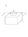
- FIG. 1 is a perspective view showing an example of the appearance of the rotary operation device 100 according to the present embodiment.
- FIG. 2 is a partial cutaway view of the rotary operation device 100 in a cross section passing through line 2-2 shown in FIG.
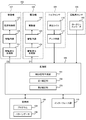
- FIG. 3 is a block diagram showing an example of the configuration of the rotary operation device 100 shown in FIG.
- the rotary operation device 100 includes an operation member 102 that can be rotated according to an operator's rotation operation, and a housing 101 that rotatably supports the operation member 102.
- the rotary operation device 100 generates operation information related to a rotation operation such as a rotation angle, a rotation position, and a rotation speed of the operation member 102.
- the rotary operation device 100 is used, for example, for adjusting the volume in an audio device or switching a transmission in a vehicle.
- the operation member 102 includes a shaft 112 that is rotatably supported by the housing 101, and a knob 111 that is fixed to the shaft 112.
- the shaft 112 is accommodated in the housing 101.
- the knob 111 is exposed to the outside of the housing 101 and receives an operator's rotation operation.
- the knob 111 and the shaft 112 have a columnar shape with the rotation axis AX as the central axis, and rotate integrally around the rotation axis AX.
- the rotary operation device 100 includes a torque generation unit 103, a torque sensor 104, and a rotation angle sensor 105 as a mechanical system configuration.
- the torque generator 103, the torque sensor 104, and the rotation angle sensor 105 are housed inside the casing 101 and are provided along the shaft 112 of the operation member 102.
- the rotary operation device 100 further includes a processing unit 108, a storage unit 109, and an interface unit 110 as a configuration of the control system.
- the torque generator 103 generates a control torque T1 for rotationally driving or braking the operation member 102 in accordance with control signals (D1, D2) input from the processing unit 108 (FIG. 3) described later.
- the torque generating unit 103 includes a driving machine 106 and a brake 107.
- the driving machine 106 generates a driving torque Td that rotationally drives the operation member 102 in accordance with the first control signal D1 input from the processing unit 108.
- the drive machine 106 includes an electric motor 120 such as a DC motor, for example, as shown in FIG.
- the electric motor 120 includes a plurality of rotors 121 that rotate integrally with the shaft 112, and a plurality of stators 122 that are disposed to face the rotor 121.
- the rotor 121 is a permanent magnet, for example, and the stator 122 is a coil, for example.
- a magnetic field acting on the plurality of rotors 121 is generated, and a drive torque Td for rotating the plurality of rotors 121 together with the shaft 112 is generated.
- the magnitude of the drive torque Td changes according to the magnitude of the drive current supplied to the stator 122 coil.
- the drive unit 106 further includes a drive circuit 123 and a drive signal generation unit 124 as shown in FIG.
- the drive circuit 123 generates a drive current corresponding to the input drive signal and supplies the drive current to the plurality of stators 122 of the electric motor 120.
- the drive signal generation unit 124 generates a drive signal corresponding to the first control signal D ⁇ b> 1 input from the processing unit 108 and inputs the drive signal to the drive circuit 123.
- the first control signal D1 is a signal for setting the magnitude of the drive current supplied to the coil of the stator 122.
- the drive signal generator 124 generates a drive signal so that a drive current corresponding to the setting of the first control signal D1 is supplied.
- the drive signal generation unit 124 includes a D / A converter that outputs an analog drive signal having an amplitude corresponding to the signal value (digital value) of the first control signal D1.
- the drive signal generation unit 124 may include a smoothing circuit that smoothes a PWM signal that has been pulse width modulated in accordance with the signal value (digital value) of the first control signal D1 and outputs the PWM signal as a drive signal.
- the driving device 106 is not limited to the above-described electric motor 120, and may include various types of prime movers that generate torque based on other power sources.
- the brake 107 generates a braking torque Tb that brakes the rotation of the operation member 102 in response to the second control signal D2 input from the processing unit 108.
- the brake 107 includes a magnetorheological fluid 134 that is in contact with the operation member 102 and a magnetic field control unit 132 that controls a magnetic field acting on the magnetorheological fluid 134.
- the magnetic field control unit 132 generates a magnetic field according to the second control signal D2, and changes the viscosity of the magnetorheological fluid 134 by the magnetic field.
- the magnetic field control unit 132 is a coil that is wound around the shaft 112 in an annular shape.
- the magnetic field control unit 132 is disposed in an annular coil case 131 fixed to the shaft 112 of the operation member 102.
- the coil case 131 has a facing surface 133 that is substantially perpendicular to the rotation axis AX.
- a disc-shaped resistance board 135 having a surface substantially perpendicular to the rotation axis AX is fixed to the shaft 112, and one surface of the resistance board 135 and the facing surface 133 of the coil case 131 are arranged close to each other.
- the magnetorheological fluid 134 is filled in a gap between the facing surface 133 of the coil case 131 and the resistance board 135 and is confined in the gap by a seal member (not shown).
- the magnetic field passing through the magnetorheological fluid 134 changes, the change in the magnetic field changes the binding force of the particles constituting the magnetorheological fluid 134, and the change in the binding force of the particles causes magnetism.
- the viscosity of the viscous fluid 134 changes.
- a force that prevents relative rotation between the coil case 131 and the resistance board 135, that is, a frictional force changes.
- the braking torque Tb for braking the rotation of the operation member 102 increases.
- the magnitude of the braking torque Tb changes according to the magnitude of the drive current flowing through the magnetic field control unit 132.
- the brake 107 further includes a drive circuit 136 and a drive signal generation unit 137 as shown in FIG.
- the drive circuit 136 generates a drive current corresponding to the input drive signal and supplies it to the magnetic field control unit 132.
- the drive signal generation unit 137 generates a drive signal corresponding to the second control signal D ⁇ b> 2 input from the processing unit 108 and inputs the drive signal to the drive circuit 136.
- the second control signal D2 is a signal for setting the magnitude of the drive current supplied to the magnetic field control unit 132.
- the drive signal generation unit 137 generates a drive signal so that a drive current according to the setting of the second control signal D2 is supplied.
- the drive signal generation unit 137 includes a D / A converter that outputs an analog drive signal having an amplitude corresponding to the signal value (digital value) of the second control signal D2.
- the drive signal generation unit 137 may include a smoothing circuit that smoothes a PWM signal that has been pulse width modulated in accordance with the signal value (digital value) of the second control signal D2 and outputs the PWM signal as a drive signal.
- the brake 107 is not limited to the one using the viscosity of the magnetorheological fluid 134 as described above, and may generate the braking torque Tb by various other methods.
- the brake 107 may generate the braking torque Tb by a method in which a member is mechanically brought into contact with the operation member 102 or a method using electromagnetic force.
- the rotation angle sensor 105 is a sensor that detects the rotation angle of the operation member 102 and includes, for example, a rotary encoder 140.
- the rotary encoder 140 includes a disc-shaped detection board 141 fixed to the shaft 112 of the operation member 102 and an optical detection unit 142 disposed in the vicinity of the outer periphery of the detection board 141. Including. In the detection board 141, a plurality of holes are formed in the vicinity of the outer peripheral edge. The optical detection unit 142 optically detects the presence or absence of this hole. The rotation angle of the operation member 102 is detected based on the detection result of the optical detection unit 142.
- the rotation angle sensor 105 is not limited to the rotary encoder 140 described above, and the rotation angle may be detected by various other methods.
- the rotation angle sensor 105 may detect the rotation angle based on a change in magnetic field by a permanent magnet fixed to the shaft 112, or a sensor whose resistance value or other physical quantity changes according to the rotation of the shaft 112. The rotation angle may be detected by.
- the torque sensor 104 detects a torsion torque Ts that acts between a portion of the operation member 102 to which the operation torque T2 of the rotation operation is applied and a portion to which the control torque T1 of the torque generation unit 103 is applied. That is, the torque sensor 104 detects the torsion torque Ts that acts between the portion where the driving torque Td and the braking torque Tb are applied to the shaft 112 and the portion where the knob 111 is fixed.
- the torque sensor 104 detects the torsion torque Ts using, for example, the magnetostriction effect of a ferromagnetic material.
- the torque sensor 104 includes magnetostrictive films 115A and 115B formed on the shaft 112, a detection coil 116A wound around the magnetostrictive film 115A, and a detection coil 116B wound around the magnetostrictive film 115B. And have.
- the detection coils 116 ⁇ / b> A and 116 ⁇ / b> B are collectively referred to as “detection coil 116”.
- Torque sensor 104 includes an amplifier circuit 117 that amplifies the difference between the output signals of detection coils 116A and 116B.
- the magnetostrictive films 115 ⁇ / b> A and 115 ⁇ / b> B have magnetic anisotropies in opposite directions, and when one of the magnetic permeability increases according to the torsional torque Ts acting on the shaft 112, the other magnetic permeability decreases.
- the detection coils 116A and 116B are magnetically coupled to an excitation coil (not shown), and each output an electromagnetically induced signal in accordance with a signal applied to the excitation coil.
- the difference between the output signals of the detection coils 116A and 116B changes according to the difference in magnetic permeability between the magnetostrictive films 115A and 115B, and represents the magnitude of the torsion torque Ts.
- the torque sensor 104 outputs a signal corresponding to the difference between the output signals of the detection coils 116A and 116B as the detection result of the torsion torque Ts.
- the torque sensor 104 is not limited to the method using the magnetostriction effect described above, and may detect torsion torque by various other methods.
- the torque sensor 104 may detect the torsion torque Ts by a method of outputting a signal of a torque gauge attached to the shaft 112 via a slip ring or the like.
- the knob 111 is fixed to one side of the shaft 112 with the torque sensor 104 interposed therebetween, and the rotation angle sensor 105 and the torque generating unit 103 are provided on the other side of the shaft 112.
- the rotation angle sensor 105 is located closer to the torque sensor 104 than the torque generation unit 103, and in the torque generation unit 103, the driving machine 106 is located closer to the torque sensor 104 than the brake 107. .
- the processing unit 108 is a device that executes processes related to the operation of the rotary operation device 100 and processes such as data input / output.
- the processing unit 108 is a computer that executes various processes based on a program 155 stored in the storage unit 109. including.
- the processing unit 108 may execute all processing by a computer, or may execute at least part of processing by dedicated hardware (logic circuit).
- the processing unit 108 includes a control signal generation unit 151, a first correction unit 152, and a second correction unit 153 as components that perform processing related to control of torque (control torque T ⁇ b> 1) generated in the torque generation unit 103. .
- the control signal generation unit 151 generates control signals (D1, D2) corresponding to the detected value of the rotation angle in the rotation angle sensor 105. That is, the control signal generation unit 151 includes a preset correspondence between the rotation angle of the operation member 102 and the signal value of the first control signal D1, and the rotation angle of the operation member 102 and the signal value of the second control signal D2. The first control signal D1 and the second control signal D2 having a signal value corresponding to the detected value of the rotation angle are generated based on the preset correspondence relationship.
- the correspondence between the rotation angle of the operation member 102 and the signal value of the first control signal D1 and the correspondence between the rotation angle of the operation member 102 and the signal value of the second control signal D2 are stored as pattern data 156 in the storage unit 109.
- Stored in The control signal generation unit 151 generates a first control signal D1 and a second control signal D2 corresponding to the detected value of the rotation angle with reference to the pattern data 156.
- FIG. 4 is a block diagram showing an example of a configuration relating to generation and correction of control signals (D1, D2) of the control torque T1.
- the control signal generation unit 151 includes an angle data generation unit 161, a first control signal generation unit 162, and a second control signal generation unit 163.
- the angle data generation unit 161 generates angle data A corresponding to the detected value of the rotation angle in the rotation angle sensor 105. For example, the angle data generation unit 161 converts the detection value of the rotation angle in the range in which the operation member 102 can be rotated into the angle data A representing the relative rotation angle in each of a plurality of angle ranges included in this range. Convert. As a specific example, it is assumed that the range in which rotation is possible is not limited, and the range of one rotation (360 °) is divided into 12 angle ranges, and each angle range has a width of 30 °. In this case, the angle data generation unit 161 changes the angle data A 12 times from 0 ° to 30 ° while the detected value of the rotation angle changes from 0 ° to 360 °.
- the first control signal generator 162 has a signal value corresponding to the angle data A based on the correspondence between the signal value of the first control signal D1 included in the pattern data 156 and the angle data A. Is generated.
- the second control signal generation unit 163 generates a second control signal D2 having a signal value corresponding to the angle data A based on the correspondence relationship between the signal value of the second control signal D2 included in the pattern data 156 and the angle data A. Is generated.
- FIG. 5 is a diagram showing an example of the first control signal D1 and the second control signal D2 that change according to the rotation angle, and the corresponding drive torque Td and control torque T1.
- the horizontal axis in FIG. 5 indicates the change in the rotation angle in one direction with the rotation direction of the operation member 102 being positive.
- the positive first control signal D1 in FIG. 5 indicates that the drive torque Td is generated in a direction that suppresses the rotation of the operation member 102, and the negative first control signal D1 is a direction that promotes the rotation of the operation member 102. Indicates that the drive torque Td is generated.
- the second control signal D2 in FIG. 5 specifies the magnitude of the braking torque Tb.
- the control torque T1 in FIG. 5 indicates the sum of the driving torque Td and the braking torque Tb, and the meaning of the positive and negative signs is the same as the driving torque Td. Note that the control torque T1 illustrated in FIG. 5 is obtained when the operation member 102 is rotated at a constant speed, and has not been corrected by the first correction unit 152 described later.
- the control signal generation unit 151 When the rotation direction of the operation member 102 is reversed clockwise and counterclockwise, for example, the control signal generation unit 151 generates the first control signal D1 and the second control signal D2 similar to those in FIG. 5 in each rotation direction. It's okay.
- the positive first control signal D1 in FIG. 5 indicates that the drive torque Td is generated in the direction in which the rotation of the operation member 102 is suppressed
- the negative first control signal D1 is It shows that the drive torque Td is generated in the direction of promoting the rotation of the operation member 102.
- the change pattern of the first control signal D1 with respect to the change of the rotation angle is the same in two consecutive angle ranges R0-1 and R0-2.
- the range of one rotation includes a plurality of angle ranges similar to the angle ranges R0-1 and R0-2. These multiple angle ranges are referred to as “R0” without distinction.
- the angle data generation unit 161 generates angle data A that similarly changes from the start point to the end point in each angle range R0.
- the 1st control signal generation part 162 and the 2nd control signal generation part 163 generate the 1st control signal D1 and the 2nd control signal D2 which change similarly in each angle range R0.
- one angle range R0 includes a first section R1 and a second section R2.
- the first control signal D1 continuously changes from the negative peak value DL1 to the positive peak value DH1, and the drive torque Td has a negative peak value. It continuously changes from TL1 to the positive peak value TH1.
- the first control signal D1 becomes zero, and the driving torque Td correspondingly becomes zero.
- the first control signal D1 continuously changes from the positive peak value DH1 to the negative peak value DL1, and the driving torque Td has a positive peak value. It continuously changes from TH1 to a negative peak value TL1.
- the first control signal D1 becomes zero, and the driving torque Td correspondingly becomes zero.
- the drive torque Td Acts in the direction of promoting the rotation of the operation member 102 (hereinafter, sometimes referred to as “promoting direction”).
- the drive torque Td is positive. Acts in a direction in which the rotation of the operation member 102 is suppressed (hereinafter may be referred to as a “inhibition direction”).
- the second control signal D2 is held at a constant value DL2. Therefore, the braking torque Tb of the brake 107 is also held at a constant value TM3.
- the graph of the control torque T1 shown in FIG. 5 is the positive direction of the graph of the drive torque Td shown in FIG. 5 by the value TM3 of the braking torque Tb. It will be shifted.
- the control torque T1 becomes zero in the angle data A5 of the first section R1.
- the control torque T1 increases in the positive direction and the control torque T1 in the suppression direction increases, so that the operator feels a gradually increasing resistance.
- the angle data exceeds “A3”
- the control torque T1 changes from increasing to decreasing, so the operator feels a change in the resistance.
- the control torque T1 in the positive direction gradually decreases, so that the operator feels that the resistance force is lightened.
- control torque T1 becomes zero in the middle of the rotation and further increases in the negative direction
- the control torque T1 in the acceleration direction increases, so that the operator feels drawn by the operation member 102 in the rotation direction.
- the pulling force in the acceleration direction becomes weak, and the pulling force becomes zero in the angle data A5 where the control torque T1 becomes zero. Therefore, the operator can stably stop the rotation of the operation member 102 at the position of the angle data A5.
- the first correction unit 152 controls the correction torque for making the apparent moment of inertia of the operation member 102 with respect to the rotation operation different from the original virtual moment based on the time change of the detection value of the rotation angle in the rotation angle sensor 105.
- the control signals (D1, D2) are corrected so as to be added to the torque T1.
- FIG. 6 is a diagram for explaining torques acting on each part of the rotary operation device 100 shown in FIG.
- “T1” indicates the control torque generated by the torque generator 103
- “T2” indicates the operation torque applied to the knob 111 by the operator's rotation operation
- “Ts” is detected by the torque sensor 104. Shows the torsion torque to be applied.
- “Tf” indicates an error torque corrected by a second correction unit 153 described later.
- ⁇ 2 indicates the angular acceleration of the knob 111
- ⁇ 1 indicates the rotational acceleration of the torque generating unit 103.
- the angular accelerations “ ⁇ 1” and “ ⁇ 2” are assumed to be equal to the angular acceleration “ ⁇ ”.
- J1 indicates the moment of inertia of the rotating member (rotor 121, resistance board 135, detection board 141, part of the shaft 112, etc.) on the torque generating unit 103 side as viewed from the torque sensor 104.
- J2 indicates the original moment of inertia of the rotating member (knob 111, part of the shaft 112) on the knob 111 side as viewed from the torque sensor 104.
- equation (1) can be transformed into the following equation.
- Equation (2) can be further transformed into the following equation.
- the first correction unit 152 performs correction by adding the correction torque “k ⁇ J2 ⁇ ⁇ ” to the control torque T1. That is, the first correction unit 152 calculates the angular acceleration ⁇ of the operation member 102 based on the detected value of the rotation angle of the rotation angle sensor 105, and is estimated based on the moment of inertia J2 and the angular acceleration ⁇ .
- the control signals (D1, D2) are corrected so that the correction torque “k ⁇ J2 ⁇ ⁇ ” corresponding to the torque Ti1 is added to the control torque T1.
- the first inertia torque Ti1 is “J2 ⁇ ⁇ ” expressed by Expression (1).
- the first correction unit 152 includes an angular acceleration calculation unit 164, an inertia torque calculation unit 165, a correction signal generation unit 166, and an addition unit 167.
- the angular acceleration calculation unit 164 calculates the angular acceleration ⁇ by performing second-order differentiation of the rotation angle detection value ⁇ in the rotation angle sensor 105.
- the inertia torque calculator 165 calculates the first inertia torque Ti1 by multiplying the angular acceleration ⁇ calculated by the angular acceleration calculator 164 by the inertia moment J2.
- the correction signal generation unit 166 generates a correction signal for correcting the first control signal D1 so that the correction torque “k ⁇ J2 ⁇ ⁇ ” is added to the control torque T1.
- the addition unit 167 adds the correction signal generated by the correction signal generation unit 166 to the first control signal D1 generated by the first control signal generation unit 162.
- the first correction unit 152 corrects only the first control signal D1, but in another example of this embodiment, both the first control signal D1 and the second control signal D2 or Only the second control signal D2 may be corrected, and the correction torque “k ⁇ J2 ⁇ ⁇ ” may be added to the control torque T1.
- the second correction unit 153 controls the control torque T1 estimated based on the detected value of the torsion torque Ts in the torque sensor 104 and the detected value of the rotation angle in the rotation angle sensor 105, and the control corresponding to the control signals (D1, D2).
- the control signals (D1, D2) are corrected so that the error torque Tf, which is the difference from the torque T1, becomes small.
- the error torque Tf is generated due to, for example, sliding friction of the electric motor 120 in the driving device 106, temperature change of the viscosity of the magnetorheological fluid 134 in the brake 107, or the like.
- T1 J1 ⁇ + Ts + Tf (5)
- T1A J1 ⁇ ⁇ + Ts (6)
- the error torque Tf is expressed by the following equation from Equation (5) and Equation (6).
- the signal value of the first control signal D1 is “D1”
- the coefficient for converting the signal value D1 into the driving torque Td is “Kd”
- the signal value of the second control signal D2 is “D2”
- the signal value D2 (7) can be transformed into the following equation, where “Kb” is a coefficient for converting to a braking torque Tb.
- the second correction unit 153 calculates the error torque Tf based on the relationship of Expression (8). That is, the second correction unit 153 calculates the angular acceleration ⁇ of the operation member 102 based on the rotation angle detection value of the rotation angle sensor 105, and calculates the second inertia torque Ti2 based on the inertia moment J1 and the angular acceleration ⁇ .
- the error torque Tf which is the difference between the control torque T1A calculated and estimated based on the detected value of the torsion torque Ts and the second inertia torque Ti2 and the control torque T1 corresponding to the control signals (D1, D2) is small.
- the control signals (D1, D2) are corrected so that Here, the second inertia torque Ti2 is “J1 ⁇ ⁇ ”.
- the second correction unit 153 includes an angular acceleration calculation unit 168, an inertia torque calculation unit 169, a drive torque calculation unit 170, a braking torque calculation unit 171, a correction signal generation unit 172, Adders 173 and 174 are included.
- the angular acceleration calculation unit 168 calculates the angular acceleration ⁇ by performing second-order differentiation of the rotation angle detection value ⁇ in the rotation angle sensor 105.
- the inertia torque calculating unit 169 calculates the second inertia torque Ti2 by multiplying the angular acceleration ⁇ calculated by the angular acceleration calculating unit 168 by the inertia moment J1.
- the driving torque calculation unit 170 calculates an estimated value of the driving torque Td by multiplying the signal value of the first control signal D1 by a coefficient Kd.
- the braking torque calculator 171 calculates an estimated value of the braking torque Tb by multiplying the signal value of the second control signal D2 by the coefficient Kb.
- the adding unit 173 calculates the estimated value of the braking torque Tb calculated by the braking torque calculating unit 171 and the second value calculated by the inertia torque calculating unit 169 from the estimated value of the driving torque Td calculated by the driving torque calculating unit 170.
- the error torque Tf is calculated by subtracting the inertia torque Ti2 and the detected value of the torsion torque Ts in the torque sensor 104.
- the correction signal generation unit 172 generates a correction signal for correcting the first control signal D1 so that torque that cancels the error torque Tf is added to the control torque T1.
- the addition unit 174 adds the correction signal generated by the correction signal generation unit 166 to the first control signal D1 generated by the first control signal generation unit 162.
- the second correction unit 153 corrects only the first control signal D1, but in another example of this embodiment, both the first control signal D1 and the second control signal D2 or Only the second control signal D2 may be corrected, and a torque that cancels the error torque Tf may be added to the control torque T1.
- the first correction unit 152 and the second correction unit 153 are each provided with the calculation unit (164, 168) of the angular acceleration ⁇ .
- the calculation unit for the angular acceleration ⁇ in the first correction unit 152 and the second correction unit 153 may be shared.
- the storage unit 109 stores constant data and variable data used for processing in the processing unit 108, data obtained as a result of the processing, and the like.
- the storage unit 109 may store a program 155 executed on the computer.
- the storage unit 109 includes, for example, a volatile memory such as a DRAM or SRAM, a nonvolatile memory such as a flash memory, a hard disk, or the like.
- the interface unit 110 is a circuit for exchanging data between the rotary operation device 100 and other devices (such as a host computer that inputs operation information from the rotary operation device 100 and uses it for processing).
- the processing unit 108 outputs information stored in the storage unit 109 (such as operation information related to the rotation operation of the operation member 102) from the interface unit 110 to a device (not shown).
- the interface unit 110 may acquire the program 155 executed on the computer of the processing unit 108 from a server on the network and load it into the storage unit 109.
- the interface unit 110 may include a reading device that reads the program 155 from a non-transitory tangible medium (such as an optical disk or a USB memory) and stores the program 155 in the storage unit 109.
- the processing unit 108 acquires a detection value of the rotation angle of the operation member 102 in the rotation angle sensor 105 and a detection value of the torsion torque Ts in the torque sensor 104.
- the control signal generation unit 151 generates a first control signal D1 and a second control signal D2 corresponding to the rotation angle detection value acquired in step ST100.
- the first correction unit 152 Based on the time change of the detected value of the rotation angle acquired in step ST100, the first correction unit 152 sets a correction torque that makes the apparent moment of inertia of the operation member 102 different from the original moment of inertia J2 as the control torque T1.
- the control signals (D1, D2) are corrected so as to be added.
- the first correction unit 152 calculates the angular acceleration ⁇ of the operation member 102 based on the detected value of the rotation angle of the rotation angle sensor 105, and is estimated based on the moment of inertia J2 and the angular acceleration ⁇ .
- a correction torque “k ⁇ J2 ⁇ ⁇ ” corresponding to the torque Ti1 is calculated.
- the first correction unit 152 corrects the control signals (D1, D2) so that the calculated correction torque “k ⁇ J2 ⁇ ⁇ ” is added to the control torque T1.
- the second correction unit 153 corrects the control signals (D1, D2) so that the error torque Tf is reduced based on the detected value of the rotation angle and the detected value of the torsion torque Ts acquired in step ST100.
- the first correction unit 152 calculates the angular acceleration ⁇ of the operation member 102 based on the detected value of the rotation angle in the rotation angle sensor 105, and calculates the second inertia torque Ti2 based on the moment of inertia J1 and the angular acceleration ⁇ .
- the difference between the control torque T1A estimated based on the detected value of the torsion torque Ts and the second inertia torque Ti2 and the control torque T1 corresponding to the control signals (D1, D2) is calculated as the error torque Tf. .
- the second correction unit 153 corrects the control signals (D1, D2) so that torque that cancels the calculated error torque Tf is added to the control torque T1.
- the processor 108 outputs the control signals (D1, D2) corrected in steps ST110 and ST115 to the torque generator 103, and generates a control torque T1 corresponding to the control signals (D1, D2).
- the apparent moment of inertia of the operation member 102 with respect to the rotation operation is converted to the original inertia based on the time change of the detected value of the rotation angle of the operation member 102 in the rotation angle sensor 105.
- the control signals (D1, D2) are corrected so that a correction torque that is different from the moment J2 is added to the control torque T1.
- the error torque that is the difference between the control torque T1A estimated based on the detected value of the torsion torque Ts and the detected value of the rotation angle and the control torque T1 corresponding to the control signals (D1, D2).
- the control signals (D1, D2) are corrected so that Tf becomes small. Since the error torque Tf is reduced by this correction, the apparent moment of inertia of the operation member 102 can be set with high accuracy. Therefore, it becomes easy to match the apparent moment of inertia of the operation member 102 with the texture of the appearance of the operation member 102, and the uncomfortable feeling of operation can be further effectively reduced.
- the driving torque Td corresponding to the first control signal D1 is generated in the driving device 106, and the braking torque Tb corresponding to the second control signal D2 is generated in the braking device 107. Therefore, a control torque T1 that produces various operational feelings can be generated by a combination of the drive torque Td and the braking torque Tb.
- the braking torque Tb applied to the operation member 102 is changed by changing the viscosity of the magnetorheological fluid 134 by the magnetic field of the magnetic field controller 132. Therefore, the braking torque Tb can be precisely controlled as compared with a method in which a mechanical friction force is applied to the operation member 102.
- the present invention is not limited to the above-described embodiments, and includes various variations.
- the shape and structure of the operation member 102 mentioned in the above-described embodiment, the generation means of the control torque T1 in the torque generation unit 103, the rotation angle detection means in the rotation angle sensor 105, and the torsional torque Ts in the torque sensor 104 The detection means and the like are merely examples, and can be replaced with other shapes, structures, mechanisms, means, and the like according to the embodiments.
- SYMBOLS 100 Rotary type operating device, 101 ... Case, 102 ... Operation member, 103 ... Torque generation part, 104 ... Torque sensor, 105 ... Rotation angle sensor, 106 ... Drive machine, 107 ... Brake, 108 ... Processing part, 109 DESCRIPTION OF SYMBOLS ... Memory
- Drive signal generator 131 131 Coil case 132 Magnetic field controller 133 Opposing surface 134 Magnetorheological fluid 135 Resistance board 136 Drive circuit 137 Drive signal generator 140 ... Rotary encoder, 141 ... Detection panel, 142 ... Optical detection unit, 151 ... Control signal generation unit, 152 ... First correction unit, 153 ... Second complement 155... Program 156 pattern data 161 angle data generation unit 162 first control signal generation unit 163 second control signal generation unit 164 angular acceleration calculation unit 165 inertia torque calculation unit 166... Correction signal generation unit, 167... Addition unit, 168... Angular acceleration calculation unit, 169... Inertia torque calculation unit, 170. Part, 174 ... addition part, D1 ...
Abstract
Description
トルク発生部103は、後述する処理部108(図3)から入力される制御信号(D1,D2)に応じて、操作部材102を回転駆動又は制動するための制御トルクT1を発生する。図2の例において、トルク発生部103は、駆動機106と制動機107を含む。 (Torque generator 103)
The
回転角センサ105は、操作部材102の回転角を検出するセンサであり、例えばロータリーエンコーダ140を含む。ロータリーエンコーダ140は、例えば図2に示すように、操作部材102のシャフト112に固定された円盤状の検出盤141と、検出盤141の外周縁付近に近接して配置された光学検知部142を含む。検出盤141には、外周縁付近に複数の穴が形成されている。光学検知部142は、この穴の有無を光学的に検知する。光学検知部142の検知結果により、操作部材102の回転角が検出される。 (Rotation angle sensor 105)
The
トルクセンサ104は、操作部材102において回転操作の操作トルクT2が印加される部分と、トルク発生部103の制御トルクT1が印加される部分との間に作用するねじれトルクTsを検出する。すなわち、トルクセンサ104は、シャフト112において駆動トルクTd及び制動トルクTbが印加される部分とノブ111が固定される部分との間に作用するねじれトルクTsを検出する。 (Torque sensor 104)
The
処理部108は、回転型操作装置100の動作に関わる制御やデータの入出力などの処理を実行する装置であり、例えば記憶部109に格納されるプログラム155に基づいて種々の処理を実行するコンピュータを含む。処理部108は、全ての処理をコンピュータによって実行しても良いし、少なくとも一部の処理を専用のハードウェア(ロジック回路)で実行してもよい。 (Processor 108)
The
制御信号生成部151は、回転角センサ105における回転角の検出値に応じた制御信号(D1,D2)を生成する。すなわち、制御信号生成部151は、操作部材102の回転角と第1制御信号D1の信号値との予め設定された対応関係、及び、操作部材102の回転角と第2制御信号D2の信号値との予め設定された対応関係に基づいて、回転角の検出値に対応した信号値を持つ第1制御信号D1及び第2制御信号D2を生成する。操作部材102の回転角と第1制御信号D1の信号値との対応関係、及び、操作部材102の回転角と第2制御信号D2の信号値との対応関係は、パターンデータ156として記憶部109に格納される。制御信号生成部151は、このパターンデータ156を参照して、回転角の検出値に応じた第1制御信号D1及び第2制御信号D2を生成する。 (Control signal generator 151)
The control
第2制御信号生成部163は、パターンデータ156に含まれる第2制御信号D2の信号値と角度データAとの対応関係に基づいて、角度データAに対応した信号値を持つ第2制御信号D2を生成する。 The first
The second control
第1補正部152は、回転角センサ105における回転角の検出値の時間変化に基づいて、回転操作に対する操作部材102の見かけ上の慣性モーメントを本来の仮想モーメントと相違させるための補正トルクが制御トルクT1に追加されるように制御信号(D1,D2)を補正する。 (First correction unit 152)
The
第2補正部153は、トルクセンサ104におけるねじれトルクTsの検出値及び回転角センサ105における回転角の検出値に基づいて推定される制御トルクT1と、制御信号(D1,D2)に対応する制御トルクT1との差である誤差トルクTfが小さくなるように制御信号(D1,D2)を補正する。 (Second correction unit 153)
The
=T1-(J1・α+Ts) … (7) Tf = T1-T1A
= T1- (J1 · α + Ts) (7)
=(Kd・D1-Kb・D2)-(J1・α+Ts) … (8) Tf = (Td−Tb) − (J1 · α + Ts)
= (Kd · D1−Kb · D2) − (J1 · α + Ts) (8)
記憶部109は、処理部108において処理に使用される定数データや変数データ、処理の結果として得られたデータなどを記憶する。処理部108がコンピュータを含む場合、記憶部109は、コンピュータにおいて実行されるプログラム155を記憶してもよい。記憶部109は、例えば、DRAMやSRAMなどの揮発性メモリ、フラッシュメモリなどの不揮発性メモリ、ハードディスクなどを含んで構成される。 (Storage unit 109)
The
インターフェース部110は、回転型操作装置100と他の装置(回転型操作装置100から操作情報を入力して処理に使用するホストコンピュータ等)との間でデータをやり取りするための回路である。処理部108は、記憶部109に記憶される情報(操作部材102の回転操作に関わる操作情報など)をインターフェース部110から図示しない装置へ出力する。 (Interface unit 110)
The
処理部108は、回転角センサ105における操作部材102の回転角の検出値と、トルクセンサ104におけるねじれトルクTsの検出値をそれぞれ取得する。 ST100:
The
制御信号生成部151は、ステップST100において取得された回転角の検出値に応じた第1制御信号D1及び第2制御信号D2をそれぞれ生成する。 ST105:
The control
第1補正部152は、ステップST100において取得された回転角の検出値の時間変化に基づいて、操作部材102の見かけ上の慣性モーメントを本来の慣性モーメントJ2と相違させる補正トルクが制御トルクT1に追加されるように制御信号(D1,D2)を補正する。例えば、第1補正部152は、回転角センサ105の回転角の検出値に基づいて操作部材102の角加速度αを算出し、慣性モーメントJ2と角加速度αとに基づいて推定される第1慣性トルクTi1に応じた補正トルク「k・J2・α」を算出する。第1補正部152は、算出した補正トルク「k・J2・α」が制御トルクT1に追加されるように制御信号(D1,D2)を補正する。 ST110:
Based on the time change of the detected value of the rotation angle acquired in step ST100, the
また第2補正部153は、ステップST100において取得された回転角の検出値とねじれトルクTsの検出値に基づいて、誤差トルクTfが小さくなるように制御信号(D1,D2)を補正する。例えば、第1補正部152は、回転角センサ105における回転角の検出値に基づいて操作部材102の角加速度αを算出し、慣性モーメントJ1と角加速度αとに基づいて第2慣性トルクTi2を算出し、ねじれトルクTsの検出値と第2慣性トルクTi2とに基づいて推定される制御トルクT1Aと、制御信号(D1,D2)に対応する制御トルクT1との差を誤差トルクTfとして算出する。第2補正部153は、算出した誤差トルクTfを相殺するトルクが制御トルクT1に追加されるように制御信号(D1,D2)を補正する。 ST115:
The
処理部108は、ステップST110及びST115において補正した制御信号(D1,D2)をトルク発生部103に出力し、制御信号(D1,D2)に応じた制御トルクT1を発生させる。 ST120:
The
例えば、上述した実施形態において挙げられている操作部材102の形状や構造、トルク発生部103における制御トルクT1の発生手段、回転角センサ105における回転角の検出手段、トルクセンサ104におけるねじれトルクTsの検出手段などは一例であり、それぞれ実施態様に合わせた他の形状、構造、機構、手段等に置き換え可能である。 The present invention is not limited to the above-described embodiments, and includes various variations.
For example, the shape and structure of the
DESCRIPTION OF
Claims (11)
- 回転操作に応じて回転可能な操作部材と、
入力される制御信号に応じて、前記操作部材を回転駆動又は制動するための制御トルクを発生するトルク発生部と、
前記操作部材の回転角を検出する回転角センサと、
前記回転角センサにおける前記回転角の検出値に応じた前記制御信号を生成する制御信号生成部と、
前記回転角の検出値の時間変化に基づいて、前記回転操作に対する前記操作部材の見かけ上の慣性モーメントを本来の慣性モーメントと相違させるための補正トルクが前記制御トルクに追加されるように前記制御信号を補正する第1補正部と
を有する回転型操作装置。 An operation member that can be rotated in accordance with a rotation operation;
A torque generator for generating a control torque for rotationally driving or braking the operation member in accordance with an input control signal;
A rotation angle sensor for detecting a rotation angle of the operation member;
A control signal generation unit that generates the control signal according to the detected value of the rotation angle in the rotation angle sensor;
The control is performed so that a correction torque for making the apparent moment of inertia of the operation member with respect to the rotation operation different from the original moment of inertia is added to the control torque based on a time change of the detected value of the rotation angle. And a first correction unit that corrects the signal. - 前記第1補正部は、前記回転角の検出値に基づいて前記操作部材の角加速度を算出し、前記操作部材の慣性モーメントと前記角加速度とに基づいて推定される第1慣性トルクに応じた前記補正トルクが前記制御トルクに追加されるように前記制御信号を補正する、
請求項1に記載の回転型操作装置。 The first correction unit calculates an angular acceleration of the operation member based on the detected value of the rotation angle, and responds to the first inertia torque estimated based on the moment of inertia of the operation member and the angular acceleration. Correcting the control signal such that the correction torque is added to the control torque;
The rotary operation device according to claim 1. - 前記操作部材において前記回転操作の操作トルクが印加される部分と前記制御トルクが印加される部分との間に作用するねじれトルクを検出するトルクセンサと、
前記ねじれトルクの検出値及び前記回転角の検出値に基づいて推定される前記制御トルクと、前記制御信号に対応する前記制御トルクとの差である誤差トルクが小さくなるように前記制御信号を補正する第2補正部とを有する、
請求項1又は2に記載の回転型操作装置。 A torque sensor that detects a torsion torque acting between a portion to which the operation torque of the rotation operation is applied and a portion to which the control torque is applied in the operation member;
The control signal is corrected so that an error torque, which is a difference between the control torque estimated based on the detected value of the torsion torque and the detected value of the rotation angle, and the control torque corresponding to the control signal becomes small. A second correction unit that
The rotary operation device according to claim 1 or 2. - 前記第2補正部は、前記回転角の検出値に基づいて前記操作部材の角加速度を算出し、前記トルクセンサからみて前記トルク発生部側の回転する部材の慣性モーメントと前記角加速度とに基づいて第2慣性トルクを算出し、前記ねじれトルクの検出値と前記第2慣性トルクとに基づいて推定される前記制御トルクと、前記制御信号に対応する前記制御トルクとの差である前記誤差トルクが小さくなるように前記制御信号を補正する、
請求項3に記載の回転型操作装置。 The second correction unit calculates an angular acceleration of the operation member based on the detected value of the rotation angle, and based on the moment of inertia of the rotating member on the torque generation unit side and the angular acceleration as viewed from the torque sensor. And calculating the second inertia torque, and the error torque that is a difference between the control torque estimated based on the detected value of the torsional torque and the second inertia torque and the control torque corresponding to the control signal The control signal is corrected so that
The rotary operation device according to claim 3. - 前記トルク発生部は、
入力される第1制御信号に応じて、前記操作部材を回転駆動する駆動トルクを発生する駆動機と、
入力される第2制御信号に応じて、前記操作部材の回転を制動する制動トルクを発生する制動機とを含み、
前記第1補正部は、前記第1制御信号及び前記第2制御信号の少なくとも一方を補正し、
前記第2補正部は、前記第1制御信号及び前記第2制御信号の少なくとも一方を補正する、
請求項3又は4に記載の回転型操作装置。 The torque generator is
A driving machine for generating a driving torque for rotationally driving the operation member in response to an input first control signal;
A brake that generates a braking torque for braking the rotation of the operation member in response to an input second control signal;
The first correction unit corrects at least one of the first control signal and the second control signal,
The second correction unit corrects at least one of the first control signal and the second control signal;
The rotary operation device according to claim 3 or 4. - 前記制動機は、
前記操作部材に接触した磁気粘性流体と、
前記第2制御信号に応じた磁界を発生し、当該磁界により前記磁気粘性流体の粘性を変化させる磁界制御部とを含む、
請求項5に記載の回転型操作装置。 The brake is
A magnetorheological fluid in contact with the operating member;
A magnetic field control unit that generates a magnetic field according to the second control signal and changes the viscosity of the magnetorheological fluid by the magnetic field,
The rotary operation device according to claim 5. - 前記制御信号生成部は、前記操作部材の回転角と前記第1制御信号の信号値との予め設定された対応関係、及び、前記操作部材の回転角と前記第2制御信号の信号値との予め設定された対応関係に基づいて、前記回転角の検出値に対応した信号値を持つ前記第1制御信号及び前記第2制御信号を生成する、
請求項5又は6に記載の回転型操作装置。 The control signal generator includes a preset correspondence relationship between the rotation angle of the operation member and the signal value of the first control signal, and the rotation angle of the operation member and the signal value of the second control signal. Generating the first control signal and the second control signal having a signal value corresponding to the detected value of the rotation angle based on a preset correspondence relationship;
The rotary operation device according to claim 5 or 6. - 前記操作部材を回転可能に支持する筐体を有し、
前記操作部材は、前記筐体によって回転可能に支持されたシャフトと、前記シャフトに固定された回転操作用のノブとを含み、
前記駆動機は、前記シャフトを回転駆動する前記駆動トルクを発生し、
前記制動機は、前記シャフトの回転を制動する前記制動トルクを発生し、
前記トルクセンサは、前記シャフトにおいて前記駆動トルク及び前記制動トルクが印加される部分と前記ノブが固定される部分との間に作用する前記ねじれトルクを検出する、
請求項5乃至7の何れか一項に記載の回転型操作装置。 A housing that rotatably supports the operation member;
The operation member includes a shaft rotatably supported by the housing, and a knob for rotation operation fixed to the shaft,
The driving machine generates the driving torque for rotating the shaft;
The brake generates the braking torque for braking the rotation of the shaft;
The torque sensor detects the torsional torque acting between a portion to which the driving torque and the braking torque are applied and a portion to which the knob is fixed in the shaft;
The rotary operation device according to any one of claims 5 to 7. - 回転型操作装置の制御方法であって、
前記回転型操作装置は、
回転操作により印加される操作トルクに応じて回転可能な操作部材と、
入力される制御信号に応じて、前記操作部材を回転駆動又は制動するための制御トルクを発生するトルク発生部と、
前記操作部材の回転角を検出する回転角センサと
を有し、
前記回転角センサにおける前記回転角の検出値に応じた前記制御信号を生成することと、
前記回転角の検出値の時間変化に基づいて、前記回転操作に対する前記操作部材の見かけ上の慣性モーメントを本来の慣性モーメントと相違させるための補正トルクが前記制御トルクに追加されるように前記制御信号を補正することとを有する、
回転型操作装置の制御方法。 A control method of a rotary operation device,
The rotary operation device includes:
An operation member rotatable according to an operation torque applied by a rotation operation;
A torque generator for generating a control torque for rotationally driving or braking the operation member in accordance with an input control signal;
A rotation angle sensor for detecting a rotation angle of the operation member;
Generating the control signal according to a detected value of the rotation angle in the rotation angle sensor;
Based on the time change of the detected value of the rotation angle, the control torque is added such that a correction torque for making the apparent moment of inertia of the operating member different from the original moment of inertia is added to the control torque. Correcting the signal,
Control method of rotary operation device. - 前記回転型操作装置は、前記操作部材において前記操作トルクが印加される部分と前記制御トルクが印加される部分との間に作用するねじれトルクを検出するトルクセンサを有しており、
前記ねじれトルクの検出値及び前記回転角の検出値に基づいて推定される前記制御トルクと、前記制御信号に対応する前記制御トルクとの差である誤差トルクが小さくなるように前記制御信号を補正することを有する、
請求項9に記載の回転型操作装置の制御方法。 The rotary operation device has a torque sensor that detects a torsion torque acting between a portion to which the operation torque is applied and a portion to which the control torque is applied in the operation member,
The control signal is corrected so that an error torque, which is a difference between the control torque estimated based on the detected value of the torsion torque and the detected value of the rotation angle, and the control torque corresponding to the control signal becomes small. Have to
The control method of the rotary operation device according to claim 9. - 請求項9又は10に記載の回転型操作装置の制御方法をコンピュータに実行させるためのプログラム。
The program for making a computer perform the control method of the rotary type operating device of Claim 9 or 10.
Priority Applications (4)
| Application Number | Priority Date | Filing Date | Title |
|---|---|---|---|
| JP2019513569A JP6896068B2 (en) | 2017-04-21 | 2018-04-10 | Rotary operating device and its control method and program |
| EP18787942.4A EP3614234A4 (en) | 2017-04-21 | 2018-04-10 | Rotary-type operation device, method for controlling same, and program |
| CN201880025533.1A CN110537156B (en) | 2017-04-21 | 2018-04-10 | Rotary operation device, control method for rotary operation device, and program |
| US16/653,474 US10839657B2 (en) | 2017-04-21 | 2019-10-15 | Rotation-type manipulation device, control method for the same, and program |
Applications Claiming Priority (2)
| Application Number | Priority Date | Filing Date | Title |
|---|---|---|---|
| JP2017-084369 | 2017-04-21 | ||
| JP2017084369 | 2017-04-21 |
Related Child Applications (1)
| Application Number | Title | Priority Date | Filing Date |
|---|---|---|---|
| US16/653,474 Continuation US10839657B2 (en) | 2017-04-21 | 2019-10-15 | Rotation-type manipulation device, control method for the same, and program |
Publications (1)
| Publication Number | Publication Date |
|---|---|
| WO2018193917A1 true WO2018193917A1 (en) | 2018-10-25 |
Family
ID=63855853
Family Applications (1)
| Application Number | Title | Priority Date | Filing Date |
|---|---|---|---|
| PCT/JP2018/015101 WO2018193917A1 (en) | 2017-04-21 | 2018-04-10 | Rotary-type operation device, method for controlling same, and program |
Country Status (5)
| Country | Link |
|---|---|
| US (1) | US10839657B2 (en) |
| EP (1) | EP3614234A4 (en) |
| JP (1) | JP6896068B2 (en) |
| CN (1) | CN110537156B (en) |
| WO (1) | WO2018193917A1 (en) |
Families Citing this family (1)
| Publication number | Priority date | Publication date | Assignee | Title |
|---|---|---|---|---|
| US11618163B2 (en) * | 2018-12-27 | 2023-04-04 | Fanuc Corporation | Industrial robot system |
Citations (5)
| Publication number | Priority date | Publication date | Assignee | Title |
|---|---|---|---|---|
| JPH10177387A (en) * | 1996-10-18 | 1998-06-30 | Yamaha Corp | Tactile force driving device, tactile force applying method and recording medium |
| JP2004114201A (en) | 2002-09-25 | 2004-04-15 | Alps Electric Co Ltd | Inner force sense providing input device |
| JP2010108009A (en) * | 2008-10-28 | 2010-05-13 | Suzuki Motor Corp | Inner force sense presentation device and motorcycle shift simulator |
| JP2010211270A (en) * | 2009-03-06 | 2010-09-24 | Alps Electric Co Ltd | Operation feel feedback input device |
| JP2016096833A (en) * | 2014-11-18 | 2016-05-30 | 日本遠隔制御株式会社 | Transmitter for radio control |
Family Cites Families (26)
| Publication number | Priority date | Publication date | Assignee | Title |
|---|---|---|---|---|
| JPH04133858A (en) * | 1990-09-22 | 1992-05-07 | Toyoda Gosei Co Ltd | Device for providing counter-steering force |
| JP3010898B2 (en) * | 1992-03-10 | 2000-02-21 | トヨタ自動車株式会社 | Power steering device |
| JP3271324B2 (en) * | 1992-08-26 | 2002-04-02 | 株式会社セガ | Simulated steering device |
| JP2843230B2 (en) * | 1992-11-25 | 1999-01-06 | 松下電工株式会社 | Operation feeling realizing method, device and switch |
| JP3170367B2 (en) * | 1992-12-07 | 2001-05-28 | 松下電工株式会社 | Impedance control method and simulator |
| JP3669593B2 (en) * | 1995-02-28 | 2005-07-06 | 株式会社タイトー | Simulated operation force control device |
| US6636197B1 (en) * | 1996-11-26 | 2003-10-21 | Immersion Corporation | Haptic feedback effects for control, knobs and other interface devices |
| JP2002181062A (en) * | 2000-12-13 | 2002-06-26 | Nippon Columbia Co Ltd | Rotating knob |
| JP2002329434A (en) * | 2001-04-27 | 2002-11-15 | Matsushita Electric Ind Co Ltd | Operating knob |
| JP4209235B2 (en) * | 2003-03-28 | 2009-01-14 | アルプス電気株式会社 | Haptic input device |
| JP2005019113A (en) * | 2003-06-25 | 2005-01-20 | Alps Electric Co Ltd | Tactile force applying type input device |
| JP4180455B2 (en) * | 2003-07-24 | 2008-11-12 | アルプス電気株式会社 | Haptic input device |
| JP2007141502A (en) * | 2005-11-15 | 2007-06-07 | Teikoku Tsushin Kogyo Co Ltd | Decorative structure of electronic component |
| JP5014898B2 (en) * | 2007-06-29 | 2012-08-29 | Thk株式会社 | Steering for drive simulator and drive simulator |
| JP5436532B2 (en) * | 2008-03-27 | 2014-03-05 | マクソン モーター アーゲー | Double differential semi-active actuator suitable for interactive tasks and high-speed operation |
| FR2930655B1 (en) * | 2008-04-29 | 2013-02-08 | Commissariat Energie Atomique | EFFORT RETURN INTERFACE WITH ENHANCED SENSATION |
| JP2010177387A (en) * | 2009-01-28 | 2010-08-12 | Panasonic Corp | Nonvolatile memory device and driving method |
| WO2011062910A1 (en) * | 2009-11-17 | 2011-05-26 | Immersion Corporation | Systems and methods for a friction rotary device for haptic feedback |
| JP5440874B2 (en) * | 2010-09-30 | 2014-03-12 | アイシン・エィ・ダブリュ株式会社 | Control device |
| JP2012155674A (en) * | 2011-01-28 | 2012-08-16 | Nikon Corp | Operation unit and electronic apparatus |
| JP2013046514A (en) * | 2011-08-25 | 2013-03-04 | Semiconductor Components Industries Llc | Drive signal generation circuit |
| JP2013096854A (en) * | 2011-11-01 | 2013-05-20 | Suzuki Motor Corp | Motorcycle shift simulation system and method for predicting shift feeling of motorcycle |
| JP6366903B2 (en) * | 2013-05-13 | 2018-08-01 | 株式会社栗本鐵工所 | Radio control transmitter |
| WO2015186616A1 (en) * | 2014-06-02 | 2015-12-10 | 株式会社明電舎 | Control device for chassis dynamometer |
| FR3026553B1 (en) * | 2014-09-29 | 2021-03-19 | Commissariat Energie Atomique | HAPTICAL INTERFACE TAKING INTO ACCOUNT THE USER'S ACTION INTENT |
| JP6593796B2 (en) * | 2016-03-28 | 2019-10-23 | アルプスアルパイン株式会社 | Operating device |
-
2018
- 2018-04-10 EP EP18787942.4A patent/EP3614234A4/en not_active Withdrawn
- 2018-04-10 WO PCT/JP2018/015101 patent/WO2018193917A1/en active Application Filing
- 2018-04-10 JP JP2019513569A patent/JP6896068B2/en active Active
- 2018-04-10 CN CN201880025533.1A patent/CN110537156B/en active Active
-
2019
- 2019-10-15 US US16/653,474 patent/US10839657B2/en active Active
Patent Citations (5)
| Publication number | Priority date | Publication date | Assignee | Title |
|---|---|---|---|---|
| JPH10177387A (en) * | 1996-10-18 | 1998-06-30 | Yamaha Corp | Tactile force driving device, tactile force applying method and recording medium |
| JP2004114201A (en) | 2002-09-25 | 2004-04-15 | Alps Electric Co Ltd | Inner force sense providing input device |
| JP2010108009A (en) * | 2008-10-28 | 2010-05-13 | Suzuki Motor Corp | Inner force sense presentation device and motorcycle shift simulator |
| JP2010211270A (en) * | 2009-03-06 | 2010-09-24 | Alps Electric Co Ltd | Operation feel feedback input device |
| JP2016096833A (en) * | 2014-11-18 | 2016-05-30 | 日本遠隔制御株式会社 | Transmitter for radio control |
Non-Patent Citations (1)
| Title |
|---|
| See also references of EP3614234A4 |
Also Published As
| Publication number | Publication date |
|---|---|
| EP3614234A4 (en) | 2020-12-30 |
| CN110537156A (en) | 2019-12-03 |
| US10839657B2 (en) | 2020-11-17 |
| CN110537156B (en) | 2023-07-11 |
| US20200043304A1 (en) | 2020-02-06 |
| JP6896068B2 (en) | 2021-06-30 |
| JPWO2018193917A1 (en) | 2020-01-23 |
| EP3614234A1 (en) | 2020-02-26 |
Similar Documents
| Publication | Publication Date | Title |
|---|---|---|
| EP3650993A1 (en) | Devices and methods for controlling a haptic actuator | |
| JP3822565B2 (en) | Servo control device | |
| JP6314752B2 (en) | Electric steering control device | |
| US10916108B2 (en) | Rotation-type manipulation device, control method for the same, and program | |
| Heins et al. | Accurate torque ripple measurement for PMSM | |
| US10930445B2 (en) | Rotary operating device, method of controlling rotary operating device, and storage medium | |
| US10963051B2 (en) | Hybrid haptic interface with improved haptic feedback | |
| TW201208245A (en) | Motor control device | |
| WO2015071974A1 (en) | Control device for rotary machine, and electric power steering apparatus | |
| WO2018193917A1 (en) | Rotary-type operation device, method for controlling same, and program | |
| Chiaradia et al. | Compact series visco-elastic joint (svej) for smooth torque control | |
| Hallal et al. | Study of electromagnetic forces computation methods for machine vibration estimation | |
| JP2580997Y2 (en) | Rotary shaft system torsional vibration damper | |
| JP6654868B2 (en) | Virtual load application device | |
| JP4895737B2 (en) | Motor control device | |
| Půst | Nonlinear effects on the rotor driven by a motor with limited power | |
| KR20230119391A (en) | Apparatus and method for controlling steer-by-wire system | |
| Lobur et al. | Experimental Analysis of Rotary Speed Observers for Electric Drive with Cascaded Control System | |
| JP2007014126A (en) | System identification device | |
| Koyama et al. | Proposal of current integral zero power control with force feedforward for helical motor | |
| Gatti et al. | A combined feedforward and feedback control strategy to improve the dynamic performance of cam-follower systems | |
| WO2019188154A1 (en) | Motor driving device | |
| Makin et al. | Speed estimation and control in a belt-driven system for a web production process. Part 2: control strategy | |
| JP5063981B2 (en) | Electric motor position control device | |
| Lee | Mechanical design and internet-based control of the Gyrobot |
Legal Events
| Date | Code | Title | Description |
|---|---|---|---|
| 121 | Ep: the epo has been informed by wipo that ep was designated in this application |
Ref document number: 18787942 Country of ref document: EP Kind code of ref document: A1 |
|
| ENP | Entry into the national phase |
Ref document number: 2019513569 Country of ref document: JP Kind code of ref document: A |
|
| NENP | Non-entry into the national phase |
Ref country code: DE |
|
| WWE | Wipo information: entry into national phase |
Ref document number: 2018787942 Country of ref document: EP |
|
| ENP | Entry into the national phase |
Ref document number: 2018787942 Country of ref document: EP Effective date: 20191121 |