EP2274564B1 - Furnace lining - Google Patents
Furnace lining Download PDFInfo
- Publication number
- EP2274564B1 EP2274564B1 EP09728374A EP09728374A EP2274564B1 EP 2274564 B1 EP2274564 B1 EP 2274564B1 EP 09728374 A EP09728374 A EP 09728374A EP 09728374 A EP09728374 A EP 09728374A EP 2274564 B1 EP2274564 B1 EP 2274564B1
- Authority
- EP
- European Patent Office
- Prior art keywords
- lining material
- foil
- furnace
- coil
- lining
- Prior art date
- Legal status (The legal status is an assumption and is not a legal conclusion. Google has not performed a legal analysis and makes no representation as to the accuracy of the status listed.)
- Not-in-force
Links
- 239000000463 material Substances 0.000 claims abstract description 73
- 239000011888 foil Substances 0.000 claims abstract description 62
- 230000006698 induction Effects 0.000 claims abstract description 53
- 239000002184 metal Substances 0.000 claims abstract description 38
- 229910052751 metal Inorganic materials 0.000 claims abstract description 38
- 230000004888 barrier function Effects 0.000 claims abstract description 14
- 239000011440 grout Substances 0.000 claims description 19
- 229910001220 stainless steel Inorganic materials 0.000 claims description 12
- 239000010935 stainless steel Substances 0.000 claims description 12
- 238000000034 method Methods 0.000 claims description 6
- 239000010445 mica Substances 0.000 claims description 4
- 229910052618 mica group Inorganic materials 0.000 claims description 4
- 229910000963 austenitic stainless steel Inorganic materials 0.000 claims description 3
- 239000003365 glass fiber Substances 0.000 claims description 2
- HCHKCACWOHOZIP-UHFFFAOYSA-N Zinc Chemical compound [Zn] HCHKCACWOHOZIP-UHFFFAOYSA-N 0.000 abstract description 10
- 229910052725 zinc Inorganic materials 0.000 abstract description 10
- 239000011701 zinc Substances 0.000 abstract description 10
- 238000010348 incorporation Methods 0.000 abstract description 2
- XEEYBQQBJWHFJM-UHFFFAOYSA-N Iron Chemical compound [Fe] XEEYBQQBJWHFJM-UHFFFAOYSA-N 0.000 description 8
- 238000010438 heat treatment Methods 0.000 description 8
- PXHVJJICTQNCMI-UHFFFAOYSA-N Nickel Chemical compound [Ni] PXHVJJICTQNCMI-UHFFFAOYSA-N 0.000 description 4
- 230000000694 effects Effects 0.000 description 4
- 229910052742 iron Inorganic materials 0.000 description 4
- 238000002844 melting Methods 0.000 description 4
- 230000008018 melting Effects 0.000 description 4
- 150000002739 metals Chemical class 0.000 description 4
- 239000004576 sand Substances 0.000 description 4
- 230000008901 benefit Effects 0.000 description 3
- 239000000155 melt Substances 0.000 description 3
- XLYOFNOQVPJJNP-UHFFFAOYSA-N water Substances O XLYOFNOQVPJJNP-UHFFFAOYSA-N 0.000 description 3
- 239000000853 adhesive Substances 0.000 description 2
- 230000001070 adhesive effect Effects 0.000 description 2
- 230000015556 catabolic process Effects 0.000 description 2
- 238000001816 cooling Methods 0.000 description 2
- 229910052759 nickel Inorganic materials 0.000 description 2
- 230000035515 penetration Effects 0.000 description 2
- 239000011505 plaster Substances 0.000 description 2
- RYGMFSIKBFXOCR-UHFFFAOYSA-N Copper Chemical compound [Cu] RYGMFSIKBFXOCR-UHFFFAOYSA-N 0.000 description 1
- 230000002411 adverse Effects 0.000 description 1
- 238000009835 boiling Methods 0.000 description 1
- 229910052793 cadmium Inorganic materials 0.000 description 1
- BDOSMKKIYDKNTQ-UHFFFAOYSA-N cadmium atom Chemical compound [Cd] BDOSMKKIYDKNTQ-UHFFFAOYSA-N 0.000 description 1
- 238000005266 casting Methods 0.000 description 1
- 238000010276 construction Methods 0.000 description 1
- 229910052802 copper Inorganic materials 0.000 description 1
- 239000010949 copper Substances 0.000 description 1
- 230000002939 deleterious effect Effects 0.000 description 1
- 230000001419 dependent effect Effects 0.000 description 1
- 238000000151 deposition Methods 0.000 description 1
- 238000013461 design Methods 0.000 description 1
- 230000005672 electromagnetic field Effects 0.000 description 1
- 239000007788 liquid Substances 0.000 description 1
- 238000012423 maintenance Methods 0.000 description 1
- 239000007769 metal material Substances 0.000 description 1
- 230000035699 permeability Effects 0.000 description 1
- 230000008569 process Effects 0.000 description 1
- 239000000523 sample Substances 0.000 description 1
- 239000000758 substrate Substances 0.000 description 1
- 238000012360 testing method Methods 0.000 description 1
Images
Classifications
-
- F—MECHANICAL ENGINEERING; LIGHTING; HEATING; WEAPONS; BLASTING
- F27—FURNACES; KILNS; OVENS; RETORTS
- F27D—DETAILS OR ACCESSORIES OF FURNACES, KILNS, OVENS OR RETORTS, IN SO FAR AS THEY ARE OF KINDS OCCURRING IN MORE THAN ONE KIND OF FURNACE
- F27D1/00—Casings; Linings; Walls; Roofs
- F27D1/0003—Linings or walls
- F27D1/0006—Linings or walls formed from bricks or layers with a particular composition or specific characteristics
-
- F—MECHANICAL ENGINEERING; LIGHTING; HEATING; WEAPONS; BLASTING
- F27—FURNACES; KILNS; OVENS; RETORTS
- F27B—FURNACES, KILNS, OVENS OR RETORTS IN GENERAL; OPEN SINTERING OR LIKE APPARATUS
- F27B14/00—Crucible or pot furnaces
- F27B14/06—Crucible or pot furnaces heated electrically, e.g. induction crucible furnaces with or without any other source of heat
- F27B14/061—Induction furnaces
-
- F—MECHANICAL ENGINEERING; LIGHTING; HEATING; WEAPONS; BLASTING
- F27—FURNACES; KILNS; OVENS; RETORTS
- F27B—FURNACES, KILNS, OVENS OR RETORTS IN GENERAL; OPEN SINTERING OR LIKE APPARATUS
- F27B14/00—Crucible or pot furnaces
- F27B14/08—Details specially adapted for crucible or pot furnaces
-
- F—MECHANICAL ENGINEERING; LIGHTING; HEATING; WEAPONS; BLASTING
- F27—FURNACES; KILNS; OVENS; RETORTS
- F27D—DETAILS OR ACCESSORIES OF FURNACES, KILNS, OVENS OR RETORTS, IN SO FAR AS THEY ARE OF KINDS OCCURRING IN MORE THAN ONE KIND OF FURNACE
- F27D1/00—Casings; Linings; Walls; Roofs
- F27D1/16—Making or repairing linings ; Increasing the durability of linings; Breaking away linings
- F27D1/1678—Increasing the durability of linings; Means for protecting
-
- F—MECHANICAL ENGINEERING; LIGHTING; HEATING; WEAPONS; BLASTING
- F27—FURNACES; KILNS; OVENS; RETORTS
- F27D—DETAILS OR ACCESSORIES OF FURNACES, KILNS, OVENS OR RETORTS, IN SO FAR AS THEY ARE OF KINDS OCCURRING IN MORE THAN ONE KIND OF FURNACE
- F27D11/00—Arrangement of elements for electric heating in or on furnaces
- F27D11/06—Induction heating, i.e. in which the material being heated, or its container or elements embodied therein, form the secondary of a transformer
-
- H—ELECTRICITY
- H05—ELECTRIC TECHNIQUES NOT OTHERWISE PROVIDED FOR
- H05B—ELECTRIC HEATING; ELECTRIC LIGHT SOURCES NOT OTHERWISE PROVIDED FOR; CIRCUIT ARRANGEMENTS FOR ELECTRIC LIGHT SOURCES, IN GENERAL
- H05B6/00—Heating by electric, magnetic or electromagnetic fields
- H05B6/02—Induction heating
- H05B6/22—Furnaces without an endless core
- H05B6/24—Crucible furnaces
-
- Y—GENERAL TAGGING OF NEW TECHNOLOGICAL DEVELOPMENTS; GENERAL TAGGING OF CROSS-SECTIONAL TECHNOLOGIES SPANNING OVER SEVERAL SECTIONS OF THE IPC; TECHNICAL SUBJECTS COVERED BY FORMER USPC CROSS-REFERENCE ART COLLECTIONS [XRACs] AND DIGESTS
- Y10—TECHNICAL SUBJECTS COVERED BY FORMER USPC
- Y10T—TECHNICAL SUBJECTS COVERED BY FORMER US CLASSIFICATION
- Y10T428/00—Stock material or miscellaneous articles
- Y10T428/25—Web or sheet containing structurally defined element or component and including a second component containing structurally defined particles
- Y10T428/251—Mica
-
- Y—GENERAL TAGGING OF NEW TECHNOLOGICAL DEVELOPMENTS; GENERAL TAGGING OF CROSS-SECTIONAL TECHNOLOGIES SPANNING OVER SEVERAL SECTIONS OF THE IPC; TECHNICAL SUBJECTS COVERED BY FORMER USPC CROSS-REFERENCE ART COLLECTIONS [XRACs] AND DIGESTS
- Y10—TECHNICAL SUBJECTS COVERED BY FORMER USPC
- Y10T—TECHNICAL SUBJECTS COVERED BY FORMER US CLASSIFICATION
- Y10T428/00—Stock material or miscellaneous articles
- Y10T428/26—Web or sheet containing structurally defined element or component, the element or component having a specified physical dimension
- Y10T428/263—Coating layer not in excess of 5 mils thick or equivalent
- Y10T428/264—Up to 3 mils
- Y10T428/265—1 mil or less
Definitions
- This invention relates to a lining material and method of lining a coreless induction furnace.
- Coreless induction furnaces typically comprise a refractory crucible inside a water-cooled induction coil.
- the inner face of the induction coil is usually covered by a thin layer of refractory plaster which is called the coil grout.
- a former is placed temporarily inside the coil. Refractory sand is then rammed into the space between the coil grout and a cylindrical former and compacted to form the crucible.
- this slip plane layer is formed from mica or laminates of mica and other high temperature materials.
- Coreless induction furnaces can be used to melt a variety of metals, including metals with relatively low melting temperatures such as zinc and lead. When such metals are heated beyond their melt temperatures they often turn to vapour. These vapours sometimes have the ability to penetrate the crucible, and there is a danger that they will condense onto the water cooled induction coil and cause an electrical breakdown. In such circumstances there is a need to provide a layer between the molten metal and the induction coils that will act as an effective vapour barrier to prevent metal vapour, for example zinc vapour, from reaching the coils. JP 93097017 describes such a vapour barrier.
- This layer must also withstand the maximum temperatures likely to be encountered in that area of a furnace, which could be as high as 550°C - 950°C, as well as remaining largely unaffected by the induction field.
- JP 08303965 describes a 1 mm thick stainless steel plate that can be wrapped into a coil, or two overlapping plates, which are placed between the induction coil of a furnace and the crucible.
- the thickness of the stainless steel plate is such that it is likely to be heated excessively by the induction field and would melt if used in higher power furnaces. Additionally, this heating of the 1 mm thick stainless steel plate or plates would seriously reduce the efficiency of the furnace.
- the plate or plates provided between the coil and the coil grout are permanently installed in the furnace.
- the problem to be solved is to provide an effective vapour barrier that is substantially not affected by induction fields and which may be easily installed in existing induction furnaces.
- the metal foil within the flexible lining material is impervious to the penetration of metal vapour and so will prevent harmful metal vapours from condensing onto the induction coil.
- the flexible lining material of the invention is designed to be a consumable product that can be replaced every time that a new crucible is installed into the furnace.
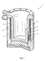
- FIG 1 shows a typical coreless induction furnace 1 comprising an outer jacket 2, with a water-cooled induction coil 4 within the jacket.
- the coil 4 is generally made of copper.
- a cylindrical former typically of a diameter 200-250 mm smaller than the coil 4 is temporarily placed inside the furnace and refractory sand is rammed into the space between the coil grout 6 and the former. The refractory sand is then compacted in a conventional manner.
- a lining material 10 is provided between the coil grout 6 and the crucible 8, the construction and function of which will be described below.
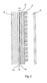
- the lining material 10 is a laminated structure comprising a thin metallic foil layer 12 interposed between two support layers 14, as shown in Figure 2 .
- the support layers 14 are heat-resistant and electrically insulating.
- the support layers 14 may be made from mica, high temperature insulating paper, a glass-fibre mat, or other similar material.
- the metallic foil 12 is made from a metallic material that is substantially not affected by induced currents. This does not exclude the presence of some induced currents in the metal; however, any currents in the metal should not cause the metal to heat up significantly. If the metal were to heat up significantly, it could melt. Even if it did not melt, significant heating of the metal would reduce the efficiency of the furnace and have other adverse effects.
- the foil 12 should be made of a metal with low electrical conductivity and permeability. This reduces the amount of heating the metal experiences when placed in an induction field. Additionally the metal should have a high melting point, be substantially impervious to vapour penetration and be capable of being bonded to a supporting substrate.
- the foil is non-magnetic. It has been found that stainless steel can be used to form an effective foil layer. There are many different forms of stainless steel, however most have melting points around 1400 °C. Additionally the nickel content of the stainless steel affects its magnetic properties, and austenitic stainless steel in particular, with relatively high nickel content, is non-magnetic. It is therefore preferable to make the foil layer 12 from austenitic stainless steel.
- the metallic foil 12 in the lining material 10 should be as thin as possible to reduce the effect of any induced currents in the metal.
- Other important factors are the melt temperature of the metal in the crucible and the thermal conductivity of the refractory used to make the crucible.
- An important parameter is the power absorbed by the foil 12 as a result of being positioned in a strong electromagnetic field. Trials have shown that in a furnace with an induction coil 4 of 1.6 m diameter and a depth of 1.6 m, operating at 2,400 kW and 50Hz, only very slight heating of 0.05 mm thick foil 12 occurred.
- induction furnaces generally operated at a mains frequency of about 50 Hz.
- medium frequency induction furnaces that operate at 150-400 Hz are becoming common.
- the induction field produced by these higher frequencies is more able to heat up the metal foil 12 than the field generated by a mains frequency furnace. Consequently, in order to counter this deleterious affect, the thickness of the metal foil 12 used in the lining material 10 has to be carefully chosen.
- Tests have indicated that the desired thickness of a stainless steel foil 12 is no more than 0.05 mm for the more powerful mains frequency and most medium frequency furnaces. In very powerful medium frequency and moderately powerful high frequency furnaces it is preferable to reduce the thickness further to about 0.025 mm. If too thick a foil layer 12 is used the metal may heat up excessively and may overload the water cooling system in the furnace. The foil may also heat to such an extent that the stainless steel would melt and therefore no longer act as a vapour barrier.
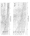
- Figures 3a and 3b illustrate the suitability of lining materials 10 having different thicknesses of stainless steel foil 12 for a range of coreless induction furnaces of varying power, frequencies and sizes.
- Figure 3a shows the suggested limit of operation for a lining material 10 having a 0.05 mm thick foil layer 12 in an induction furnace that operates at 400 Hz. The results show that this lining material should be suitable for a furnace with a grout diameter of 2 m, as long as its power is 3.5 MW or less.
- Figure 3b shows similar results for a lining material 10 having a metallic foil layer 12 with a thickness of only 0.025 mm. From these results it is suggested that this thinner material could be used in the previous example of a furnace with a grout diameter of 2 m, operating at a power of up to 7.5 MW.
- the thin metallic foil layer 12 is bonded to supporting layers 14.
- the metallic foil 12 may be bonded to the support layers 14 using any suitable means, for example adhesive.
- a supporting layer 14 is provided on both sides of the foil 12, however, a supporting layer 14 may be provided on only one side of the foil 12.
- the supporting layers 14 may be made of the same material or may be made from different materials.
- foil layer 12 it may also be possible to coat the face of a supporting layer 14 with metal using, for example, vapour deposition techniques. This would allow foil thicknesses of substantially less than 0.02 mm to be achieved.
- Zinc vapour can penetrate through the refractory sand forming the crucible wall, and can penetrate through the coil grout. If it comes into contact with the water cooled coil, it may condense leading to a short circuiting of the coil. This is a particular problem when the furnace is switched off as the walls of the crucible will shrink as they cool and cracks will form. If the crucible is not perfectly sealed the zinc vapours will easily pass through the walls and eventually to the induction coil.
- the lining material 10 may also provide a barrier to hot metal escaping through cracks in the crucible wall. As with zinc vapour, it is highly undesirable for molten metal to make contact with the coil grout 6 or with the coil 4 as this can lead to catastrophic damage to the coil 4 and the furnace 1.
- the lining material 10 contains a metallic foil 12, it may also be used to provide an early indication of a potential breakout of molten metal to the coil which, should it occur, could result in a catastrophic breakdown.
- the melt in the crucible 8 is connected to earth via a metal electrode probe, which projects through the floor of the crucible 8.
- the lining material 10 may also act as a "freeze plane" or physical barrier such that any liquid or vapour passing through the crucible wall 8 is effectively blocked by the foil so that it condenses or solidifies before reaching the induction coil 4.
- the lining material 10 can also provide a slip plane between the crucible 8 and the coil grout 6.
- the slip-plane lining material aids the removal of the crucible 8 when it needs to be replaced.
- a refractory crucible 8 may need to be replaced every month in an iron foundry, mainly due to wear of the crucible walls 8 by the molten metal being continually stirred by the induction fields.
- the lining material 10 is flexible.
- the lining material is able to be manipulated by hand and will substantially conform to the shape of the furnace walls when used to line an induction furnace 1.
- the lining material 10 may also be formed in continuous sheets and wound into rolls for ease of supply, storage and use.
- the presence of a supporting layer 14 on both sides of the metallic foil 12 also makes the material easy to handle so that it is quick and easy to line a furnace 1 before the crucible 8 is formed.
- the lining material 10 can be used as a consumable with the furnace 1 being re-lined each time a new crucible 8 is formed. This is usually necessary because slip-plane lining material is often damaged when the old crucible is being removed.
- the lining material 10 can also be applied to any size or shape of furnace.
- the lining does not have to be specially machined or shaped to fit in a particular furnace. Additionally, as the lining is not permanently installed in the furnace, maintenance costs are reduced.
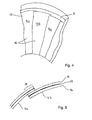
- FIG 4 shows how a furnace can be lined using a lining material 10 in accordance with the invention.
- the lining material 10 is provided in strips 16, which may be cut from a longer roll of material (not shown).
- the lining material 10 is located on the inner surface of the coil grout 6, and is typically fixed in place using suitable means such as adhesive.
- Each strip 16a, 16b, 16c etc of lining material 10 is typically laid vertically up the inner surface of the furnace wall in contact with the coil grout 6. As each subsequent strip 16 is laid it is positioned so that it overlaps the previous adjacent strip. This overlap 18, shown most clearly in Figure 5 , performs two functions.
- a continuous vapour barrier is formed around the circumference of the furnace 1 as the foil 12 within each strip 16 will overlie the foil 12 in the adjacent strip at the overlap 18.
- the overlap 18 also means that there is at least one support layer 14 between the layers of foil 12 within adjacent strips 16a, 16b.
- the support layers 14 are electrically insulating and therefore prevent electrical current passing from one strip 16 to the next, in a circumferential direction around the furnace 1.
- a continuous conductive path around the furnace 1 must be avoided as otherwise the metallic foil 12 would form a secondary circuit in its own right.
- the lining material 10 in Figure 4 is shown as not extending the full height of the furnace walls.
- the lining material 10 would in practice be laid such that it extends initially beyond the top of the furnace walls and then would be cut to length once in position. Because the lining material 10, and in particular the metallic foil layer 12, is thin, the lining material 10 may be cut with a knife or scissors.
- the lining material of the present invention therefore provides a lining for a coreless induction furnace that is easy to install.
- the incorporation of a very thin metallic foil layer in the lining material creates a vapour barrier preventing vapours such as zinc from reaching the induction coil of the furnace.
- induction furnaces by their nature are used to melt metals, careful selection of the metal used to make the foil and the thinness of the foil reduces the heating effect of the induction field to such an extent that the foil is not significantly affected by the operation of the furnace.
- the lining material is substantially unaffected by the induced currents, it does not become substantially heated by the induction field and therefore does not significantly reduce the operating efficiency of the furnace.
- the lining material of the present invention offers a number of other important advantages over previous lining systems.
- the lining material is very thin and therefore flexible and can be supplied in rolls. It is also easy to install and can be used in any furnace. It is relatively inexpensive and can be used as a consumable and replaced each time a new crucible is formed.
Landscapes
- Engineering & Computer Science (AREA)
- Mechanical Engineering (AREA)
- General Engineering & Computer Science (AREA)
- Physics & Mathematics (AREA)
- Electromagnetism (AREA)
- Power Engineering (AREA)
- Crucibles And Fluidized-Bed Furnaces (AREA)
- Laminated Bodies (AREA)
- Furnace Housings, Linings, Walls, And Ceilings (AREA)
- Furnace Details (AREA)
- Details Of Garments (AREA)
- Crystals, And After-Treatments Of Crystals (AREA)
- Secondary Cells (AREA)
- Lining Or Joining Of Plastics Or The Like (AREA)
Applications Claiming Priority (2)
| Application Number | Priority Date | Filing Date | Title |
|---|---|---|---|
| GB0806259A GB2458964A (en) | 2008-04-04 | 2008-04-04 | Induction furnace lining |
| PCT/GB2009/000853 WO2009122163A1 (en) | 2008-04-04 | 2009-03-31 | Furnace lining |
Publications (2)
| Publication Number | Publication Date |
|---|---|
| EP2274564A1 EP2274564A1 (en) | 2011-01-19 |
| EP2274564B1 true EP2274564B1 (en) | 2011-10-05 |
Family
ID=39433222
Family Applications (1)
| Application Number | Title | Priority Date | Filing Date |
|---|---|---|---|
| EP09728374A Not-in-force EP2274564B1 (en) | 2008-04-04 | 2009-03-31 | Furnace lining |
Country Status (6)
| Country | Link |
|---|---|
| US (1) | US20110111209A1 (enExample) |
| EP (1) | EP2274564B1 (enExample) |
| JP (1) | JP2011519317A (enExample) |
| AT (1) | ATE527509T1 (enExample) |
| GB (1) | GB2458964A (enExample) |
| WO (1) | WO2009122163A1 (enExample) |
Families Citing this family (13)
| Publication number | Priority date | Publication date | Assignee | Title |
|---|---|---|---|---|
| EP2715262B1 (en) * | 2011-05-23 | 2015-11-25 | Inductotherm Corp. | Electric induction furnace with lining wear detection system |
| US10598439B2 (en) * | 2011-05-23 | 2020-03-24 | Inductotherm Corp. | Electric induction furnace lining wear detection system |
| CN103047860A (zh) * | 2011-10-14 | 2013-04-17 | 重庆四联光电科技有限公司 | 双坩埚感应加热炉 |
| CN102628649A (zh) * | 2012-05-04 | 2012-08-08 | 苏州罗卡节能科技有限公司 | 一种中频感应炉 |
| WO2014022725A2 (en) | 2012-08-01 | 2014-02-06 | Allied Mineral Products, Inc. | Reinforced refractory containers |
| WO2014035480A1 (en) * | 2012-08-30 | 2014-03-06 | General Electric Company | Induction furnace with uniform cooling capability |
| CN102889789B (zh) * | 2012-09-28 | 2015-04-22 | 南车戚墅堰机车车辆工艺研究所有限公司 | 熔炼铜合金用中频感应炉的筑炉方法 |
| WO2014149369A1 (en) * | 2013-03-22 | 2014-09-25 | Applied Materials, Inc. | Reflective liners |
| WO2015047639A1 (en) * | 2013-09-30 | 2015-04-02 | Applied Materials, Inc. | Support ring with encapsulated light barrier |
| CN103805786B (zh) * | 2014-01-23 | 2015-10-28 | 佛山市诺傲再生资源科技有限公司 | 基于高效电磁感应加热的废杂镍铜锌金属料回收炉 |
| US9781776B2 (en) * | 2015-06-15 | 2017-10-03 | Pyrotek, Incorporated | Molten metal handling device heating system |
| WO2022207594A1 (en) * | 2021-03-31 | 2022-10-06 | Tata Steel Nederland Technology B.V. | Container for shielding an induction coil |
| CN114909912A (zh) * | 2022-05-13 | 2022-08-16 | 辉县市腾飞机械制造有限公司 | 一种提高中频炉使用寿命的中频炉炉衬及其制作工艺 |
Family Cites Families (23)
| Publication number | Priority date | Publication date | Assignee | Title |
|---|---|---|---|---|
| US2655550A (en) * | 1951-05-29 | 1953-10-13 | Olin Ind Inc | Melting furnace with thermocouple reception means |
| GB937213A (en) * | 1961-04-14 | 1963-09-18 | Wild Barfield Ltd | Crucible arrangements in induction furnaces |
| US3177282A (en) * | 1961-04-21 | 1965-04-06 | Ohio Crankshaft Co | High frequency induction melting furnace |
| US3372105A (en) * | 1962-10-22 | 1968-03-05 | Arthur F. Johnson | Aluminum reduction cell and insulation material therefor |
| US3715441A (en) * | 1971-07-26 | 1973-02-06 | H Collins | Induction furnace with thermocouple assembly |
| SE389957B (sv) * | 1975-04-25 | 1976-11-22 | Asea Ab | Cylinderformad langstreckt ugn for behandling av material vid hog temperatur i en gasatmosfer under hogt tryck |
| JPS6054828B2 (ja) * | 1979-10-04 | 1985-12-02 | 富士電機株式会社 | とりべの加熱装置 |
| GB2161591A (en) * | 1984-07-14 | 1986-01-15 | Ipw Limited | Coreless induction furnace |
| US4738882A (en) * | 1986-09-08 | 1988-04-19 | Bemis Company, Inc. | Static shielding sheet materials and bags formed therefrom |
| JPH02169986A (ja) * | 1988-12-23 | 1990-06-29 | Akira Hashimoto | 誘導熔解炉の内張耐火部材とその製造方法 |
| JPH0737880B2 (ja) * | 1989-06-28 | 1995-04-26 | 新日本製鐵株式会社 | 誘導溶解炉 |
| US5272720A (en) * | 1990-01-31 | 1993-12-21 | Inductotherm Corp. | Induction heating apparatus and method |
| DE4120205A1 (de) * | 1991-06-19 | 1992-12-24 | Saveway Gmbh | Vorwarneinrichtung fuer induktionsschmelzoefen |
| JPH05256583A (ja) * | 1992-03-14 | 1993-10-05 | Daido Steel Co Ltd | 溶湯貯留容器の耐火構造および該構造を使用するライニングの解体方法 |
| JPH06213572A (ja) * | 1993-01-12 | 1994-08-02 | Arishiumu:Kk | るつぼ型誘導炉 |
| JPH08303965A (ja) * | 1995-05-02 | 1996-11-22 | Shinko Electric Co Ltd | 低融点金属めっき鋼板を溶解するるつぼ形誘導炉 |
| JPH09257373A (ja) * | 1996-03-19 | 1997-10-03 | Mitsubishi Materials Corp | コアレス誘導溶解炉 |
| JPH09303970A (ja) * | 1996-05-15 | 1997-11-28 | Kitashiba Denki Kk | 誘導溶解炉 |
| US6148018A (en) * | 1997-10-29 | 2000-11-14 | Ajax Magnethermic Corporation | Heat flow sensing system for an induction furnace |
| GB2335729A (en) * | 1998-03-26 | 1999-09-29 | Elmelin Plc | Induction furnace linings |
| CN1157284C (zh) * | 1999-06-30 | 2004-07-14 | 松下电器产业株式会社 | 真空绝热材料、使用真空绝热材料的保温设备和电热水器 |
| DE20203213U1 (de) * | 2002-02-28 | 2002-09-19 | Nies, Klaus-Dieter, 65555 Limburg | Aufbau einer Feuerfestzustellung für Induktionstiegelöfen |
| JP2004116980A (ja) * | 2002-09-30 | 2004-04-15 | Nippon Steel Corp | 誘導加熱溶融炉 |
-
2008
- 2008-04-04 GB GB0806259A patent/GB2458964A/en not_active Withdrawn
-
2009
- 2009-03-31 WO PCT/GB2009/000853 patent/WO2009122163A1/en not_active Ceased
- 2009-03-31 US US12/935,433 patent/US20110111209A1/en not_active Abandoned
- 2009-03-31 JP JP2011502428A patent/JP2011519317A/ja active Pending
- 2009-03-31 EP EP09728374A patent/EP2274564B1/en not_active Not-in-force
- 2009-03-31 AT AT09728374T patent/ATE527509T1/de not_active IP Right Cessation
Also Published As
| Publication number | Publication date |
|---|---|
| GB0806259D0 (en) | 2008-05-14 |
| JP2011519317A (ja) | 2011-07-07 |
| WO2009122163A1 (en) | 2009-10-08 |
| GB2458964A (en) | 2009-10-07 |
| US20110111209A1 (en) | 2011-05-12 |
| EP2274564A1 (en) | 2011-01-19 |
| ATE527509T1 (de) | 2011-10-15 |
Similar Documents
| Publication | Publication Date | Title |
|---|---|---|
| EP2274564B1 (en) | Furnace lining | |
| AU2012258832B2 (en) | Electric induction furnace with lining wear detection system | |
| EP3159077B1 (en) | Metal transfer device | |
| JP6403693B2 (ja) | 誘導炉および格納される金属廃棄物の処理方法 | |
| CA2829284A1 (en) | Metal transfer device | |
| RU2766939C2 (ru) | Способ и устройство для определения различных переменных в носке металлургического конвертера | |
| US3412195A (en) | Intermediate furnace barrier | |
| JP3150143B2 (ja) | 誘導加熱式るつぼ | |
| JP3480786B2 (ja) | 誘導溶解炉の湯漏れ検出装置 | |
| US2997512A (en) | Coreless electric induction furnace | |
| EP0990109B1 (en) | Channel inductor | |
| KR101678130B1 (ko) | 금속 용탕으로부터 스트립을 주조하는 장치 및 방법 | |
| JP2001192728A (ja) | 円筒状金属コイルの加熱装置、及び加熱方法 | |
| JPH11269538A (ja) | 誘導加熱装置 | |
| Donsbach et al. | Crucible monitoring in induction furnaces. | |
| JPH08303965A (ja) | 低融点金属めっき鋼板を溶解するるつぼ形誘導炉 | |
| JP2004116980A (ja) | 誘導加熱溶融炉 | |
| JPH0742482U (ja) | 誘導加熱炉の湯漏れ検出装置 | |
| JPS6143827B2 (enExample) | ||
| JPH1140334A (ja) | 誘導加熱用コイルの断熱板 | |
| JP2920655B2 (ja) | 電磁浮揚溶解炉 | |
| JPH06163150A (ja) | エッジヒーターインダクター | |
| JPS62182586A (ja) | 誘導炉の湯漏れ検出装置 |
Legal Events
| Date | Code | Title | Description |
|---|---|---|---|
| PUAI | Public reference made under article 153(3) epc to a published international application that has entered the european phase |
Free format text: ORIGINAL CODE: 0009012 |
|
| 17P | Request for examination filed |
Effective date: 20101021 |
|
| AK | Designated contracting states |
Kind code of ref document: A1 Designated state(s): AT BE BG CH CY CZ DE DK EE ES FI FR GB GR HR HU IE IS IT LI LT LU LV MC MK MT NL NO PL PT RO SE SI SK TR |
|
| AX | Request for extension of the european patent |
Extension state: AL BA RS |
|
| GRAP | Despatch of communication of intention to grant a patent |
Free format text: ORIGINAL CODE: EPIDOSNIGR1 |
|
| DAX | Request for extension of the european patent (deleted) | ||
| GRAS | Grant fee paid |
Free format text: ORIGINAL CODE: EPIDOSNIGR3 |
|
| GRAA | (expected) grant |
Free format text: ORIGINAL CODE: 0009210 |
|
| AK | Designated contracting states |
Kind code of ref document: B1 Designated state(s): AT BE BG CH CY CZ DE DK EE ES FI FR GB GR HR HU IE IS IT LI LT LU LV MC MK MT NL NO PL PT RO SE SI SK TR |
|
| REG | Reference to a national code |
Ref country code: GB Ref legal event code: FG4D |
|
| REG | Reference to a national code |
Ref country code: CH Ref legal event code: EP |
|
| REG | Reference to a national code |
Ref country code: IE Ref legal event code: FG4D |
|
| REG | Reference to a national code |
Ref country code: DE Ref legal event code: R096 Ref document number: 602009002947 Country of ref document: DE Effective date: 20111215 |
|
| REG | Reference to a national code |
Ref country code: NL Ref legal event code: VDEP Effective date: 20111005 |
|
| REG | Reference to a national code |
Ref country code: DE Ref legal event code: R082 Ref document number: 602009002947 Country of ref document: DE Representative=s name: MAIKOWSKI & NINNEMANN PATENTANWAELTE, DE Ref country code: DE Ref legal event code: R082 Ref document number: 602009002947 Country of ref document: DE Representative=s name: MAIKOWSKI & NINNEMANN PATENTANWAELTE PARTNERSC, DE |
|
| PG25 | Lapsed in a contracting state [announced via postgrant information from national office to epo] |
Ref country code: SI Free format text: LAPSE BECAUSE OF FAILURE TO SUBMIT A TRANSLATION OF THE DESCRIPTION OR TO PAY THE FEE WITHIN THE PRESCRIBED TIME-LIMIT Effective date: 20111005 |
|
| LTIE | Lt: invalidation of european patent or patent extension |
Effective date: 20111005 |
|
| REG | Reference to a national code |
Ref country code: AT Ref legal event code: MK05 Ref document number: 527509 Country of ref document: AT Kind code of ref document: T Effective date: 20111005 |
|
| PG25 | Lapsed in a contracting state [announced via postgrant information from national office to epo] |
Ref country code: IS Free format text: LAPSE BECAUSE OF FAILURE TO SUBMIT A TRANSLATION OF THE DESCRIPTION OR TO PAY THE FEE WITHIN THE PRESCRIBED TIME-LIMIT Effective date: 20120205 Ref country code: LT Free format text: LAPSE BECAUSE OF FAILURE TO SUBMIT A TRANSLATION OF THE DESCRIPTION OR TO PAY THE FEE WITHIN THE PRESCRIBED TIME-LIMIT Effective date: 20111005 Ref country code: NO Free format text: LAPSE BECAUSE OF FAILURE TO SUBMIT A TRANSLATION OF THE DESCRIPTION OR TO PAY THE FEE WITHIN THE PRESCRIBED TIME-LIMIT Effective date: 20120105 Ref country code: BE Free format text: LAPSE BECAUSE OF FAILURE TO SUBMIT A TRANSLATION OF THE DESCRIPTION OR TO PAY THE FEE WITHIN THE PRESCRIBED TIME-LIMIT Effective date: 20111005 |
|
| PG25 | Lapsed in a contracting state [announced via postgrant information from national office to epo] |
Ref country code: SE Free format text: LAPSE BECAUSE OF FAILURE TO SUBMIT A TRANSLATION OF THE DESCRIPTION OR TO PAY THE FEE WITHIN THE PRESCRIBED TIME-LIMIT Effective date: 20111005 Ref country code: NL Free format text: LAPSE BECAUSE OF FAILURE TO SUBMIT A TRANSLATION OF THE DESCRIPTION OR TO PAY THE FEE WITHIN THE PRESCRIBED TIME-LIMIT Effective date: 20111005 Ref country code: HR Free format text: LAPSE BECAUSE OF FAILURE TO SUBMIT A TRANSLATION OF THE DESCRIPTION OR TO PAY THE FEE WITHIN THE PRESCRIBED TIME-LIMIT Effective date: 20111005 Ref country code: PT Free format text: LAPSE BECAUSE OF FAILURE TO SUBMIT A TRANSLATION OF THE DESCRIPTION OR TO PAY THE FEE WITHIN THE PRESCRIBED TIME-LIMIT Effective date: 20120206 Ref country code: GR Free format text: LAPSE BECAUSE OF FAILURE TO SUBMIT A TRANSLATION OF THE DESCRIPTION OR TO PAY THE FEE WITHIN THE PRESCRIBED TIME-LIMIT Effective date: 20120106 Ref country code: LV Free format text: LAPSE BECAUSE OF FAILURE TO SUBMIT A TRANSLATION OF THE DESCRIPTION OR TO PAY THE FEE WITHIN THE PRESCRIBED TIME-LIMIT Effective date: 20111005 |
|
| PG25 | Lapsed in a contracting state [announced via postgrant information from national office to epo] |
Ref country code: CY Free format text: LAPSE BECAUSE OF FAILURE TO SUBMIT A TRANSLATION OF THE DESCRIPTION OR TO PAY THE FEE WITHIN THE PRESCRIBED TIME-LIMIT Effective date: 20111005 |
|
| PG25 | Lapsed in a contracting state [announced via postgrant information from national office to epo] |
Ref country code: SK Free format text: LAPSE BECAUSE OF FAILURE TO SUBMIT A TRANSLATION OF THE DESCRIPTION OR TO PAY THE FEE WITHIN THE PRESCRIBED TIME-LIMIT Effective date: 20111005 Ref country code: BG Free format text: LAPSE BECAUSE OF FAILURE TO SUBMIT A TRANSLATION OF THE DESCRIPTION OR TO PAY THE FEE WITHIN THE PRESCRIBED TIME-LIMIT Effective date: 20120105 Ref country code: EE Free format text: LAPSE BECAUSE OF FAILURE TO SUBMIT A TRANSLATION OF THE DESCRIPTION OR TO PAY THE FEE WITHIN THE PRESCRIBED TIME-LIMIT Effective date: 20111005 Ref country code: CZ Free format text: LAPSE BECAUSE OF FAILURE TO SUBMIT A TRANSLATION OF THE DESCRIPTION OR TO PAY THE FEE WITHIN THE PRESCRIBED TIME-LIMIT Effective date: 20111005 Ref country code: DK Free format text: LAPSE BECAUSE OF FAILURE TO SUBMIT A TRANSLATION OF THE DESCRIPTION OR TO PAY THE FEE WITHIN THE PRESCRIBED TIME-LIMIT Effective date: 20111005 |
|
| PLBE | No opposition filed within time limit |
Free format text: ORIGINAL CODE: 0009261 |
|
| STAA | Information on the status of an ep patent application or granted ep patent |
Free format text: STATUS: NO OPPOSITION FILED WITHIN TIME LIMIT |
|
| PG25 | Lapsed in a contracting state [announced via postgrant information from national office to epo] |
Ref country code: RO Free format text: LAPSE BECAUSE OF FAILURE TO SUBMIT A TRANSLATION OF THE DESCRIPTION OR TO PAY THE FEE WITHIN THE PRESCRIBED TIME-LIMIT Effective date: 20111005 Ref country code: IT Free format text: LAPSE BECAUSE OF FAILURE TO SUBMIT A TRANSLATION OF THE DESCRIPTION OR TO PAY THE FEE WITHIN THE PRESCRIBED TIME-LIMIT Effective date: 20111005 Ref country code: PL Free format text: LAPSE BECAUSE OF FAILURE TO SUBMIT A TRANSLATION OF THE DESCRIPTION OR TO PAY THE FEE WITHIN THE PRESCRIBED TIME-LIMIT Effective date: 20111005 |
|
| 26N | No opposition filed |
Effective date: 20120706 |
|
| PG25 | Lapsed in a contracting state [announced via postgrant information from national office to epo] |
Ref country code: MC Free format text: LAPSE BECAUSE OF NON-PAYMENT OF DUE FEES Effective date: 20120331 |
|
| REG | Reference to a national code |
Ref country code: DE Ref legal event code: R097 Ref document number: 602009002947 Country of ref document: DE Effective date: 20120706 |
|
| REG | Reference to a national code |
Ref country code: IE Ref legal event code: MM4A |
|
| PG25 | Lapsed in a contracting state [announced via postgrant information from national office to epo] |
Ref country code: AT Free format text: LAPSE BECAUSE OF FAILURE TO SUBMIT A TRANSLATION OF THE DESCRIPTION OR TO PAY THE FEE WITHIN THE PRESCRIBED TIME-LIMIT Effective date: 20111005 Ref country code: IE Free format text: LAPSE BECAUSE OF NON-PAYMENT OF DUE FEES Effective date: 20120331 |
|
| PG25 | Lapsed in a contracting state [announced via postgrant information from national office to epo] |
Ref country code: MK Free format text: LAPSE BECAUSE OF FAILURE TO SUBMIT A TRANSLATION OF THE DESCRIPTION OR TO PAY THE FEE WITHIN THE PRESCRIBED TIME-LIMIT Effective date: 20111005 |
|
| PG25 | Lapsed in a contracting state [announced via postgrant information from national office to epo] |
Ref country code: ES Free format text: LAPSE BECAUSE OF FAILURE TO SUBMIT A TRANSLATION OF THE DESCRIPTION OR TO PAY THE FEE WITHIN THE PRESCRIBED TIME-LIMIT Effective date: 20120116 |
|
| PG25 | Lapsed in a contracting state [announced via postgrant information from national office to epo] |
Ref country code: FI Free format text: LAPSE BECAUSE OF FAILURE TO SUBMIT A TRANSLATION OF THE DESCRIPTION OR TO PAY THE FEE WITHIN THE PRESCRIBED TIME-LIMIT Effective date: 20111005 |
|
| PG25 | Lapsed in a contracting state [announced via postgrant information from national office to epo] |
Ref country code: MT Free format text: LAPSE BECAUSE OF FAILURE TO SUBMIT A TRANSLATION OF THE DESCRIPTION OR TO PAY THE FEE WITHIN THE PRESCRIBED TIME-LIMIT Effective date: 20111005 |
|
| REG | Reference to a national code |
Ref country code: CH Ref legal event code: PL |
|
| PG25 | Lapsed in a contracting state [announced via postgrant information from national office to epo] |
Ref country code: CH Free format text: LAPSE BECAUSE OF NON-PAYMENT OF DUE FEES Effective date: 20130331 Ref country code: LI Free format text: LAPSE BECAUSE OF NON-PAYMENT OF DUE FEES Effective date: 20130331 |
|
| PG25 | Lapsed in a contracting state [announced via postgrant information from national office to epo] |
Ref country code: TR Free format text: LAPSE BECAUSE OF FAILURE TO SUBMIT A TRANSLATION OF THE DESCRIPTION OR TO PAY THE FEE WITHIN THE PRESCRIBED TIME-LIMIT Effective date: 20111005 |
|
| PG25 | Lapsed in a contracting state [announced via postgrant information from national office to epo] |
Ref country code: LU Free format text: LAPSE BECAUSE OF NON-PAYMENT OF DUE FEES Effective date: 20120331 |
|
| PG25 | Lapsed in a contracting state [announced via postgrant information from national office to epo] |
Ref country code: HU Free format text: LAPSE BECAUSE OF FAILURE TO SUBMIT A TRANSLATION OF THE DESCRIPTION OR TO PAY THE FEE WITHIN THE PRESCRIBED TIME-LIMIT Effective date: 20090331 |
|
| REG | Reference to a national code |
Ref country code: FR Ref legal event code: PLFP Year of fee payment: 7 |
|
| REG | Reference to a national code |
Ref country code: FR Ref legal event code: PLFP Year of fee payment: 8 |
|
| REG | Reference to a national code |
Ref country code: FR Ref legal event code: PLFP Year of fee payment: 9 |
|
| REG | Reference to a national code |
Ref country code: FR Ref legal event code: PLFP Year of fee payment: 10 |
|
| PGFP | Annual fee paid to national office [announced via postgrant information from national office to epo] |
Ref country code: GB Payment date: 20190222 Year of fee payment: 11 Ref country code: DE Payment date: 20190304 Year of fee payment: 11 |
|
| PGFP | Annual fee paid to national office [announced via postgrant information from national office to epo] |
Ref country code: FR Payment date: 20190227 Year of fee payment: 11 |
|
| REG | Reference to a national code |
Ref country code: DE Ref legal event code: R119 Ref document number: 602009002947 Country of ref document: DE |
|
| PG25 | Lapsed in a contracting state [announced via postgrant information from national office to epo] |
Ref country code: FR Free format text: LAPSE BECAUSE OF NON-PAYMENT OF DUE FEES Effective date: 20200331 Ref country code: DE Free format text: LAPSE BECAUSE OF NON-PAYMENT OF DUE FEES Effective date: 20201001 |
|
| GBPC | Gb: european patent ceased through non-payment of renewal fee |
Effective date: 20200331 |
|
| PG25 | Lapsed in a contracting state [announced via postgrant information from national office to epo] |
Ref country code: GB Free format text: LAPSE BECAUSE OF NON-PAYMENT OF DUE FEES Effective date: 20200331 |