EP2272154B1 - Antriebsvorrichtung von fahrzeugaggregaten - Google Patents
Antriebsvorrichtung von fahrzeugaggregaten Download PDFInfo
- Publication number
- EP2272154B1 EP2272154B1 EP09734806.4A EP09734806A EP2272154B1 EP 2272154 B1 EP2272154 B1 EP 2272154B1 EP 09734806 A EP09734806 A EP 09734806A EP 2272154 B1 EP2272154 B1 EP 2272154B1
- Authority
- EP
- European Patent Office
- Prior art keywords
- gear mechanism
- housing
- driving device
- receptacle
- brush holder
- Prior art date
- Legal status (The legal status is an assumption and is not a legal conclusion. Google has not performed a legal analysis and makes no representation as to the accuracy of the status listed.)
- Active
Links
Images


Classifications
-
- H—ELECTRICITY
- H02—GENERATION; CONVERSION OR DISTRIBUTION OF ELECTRIC POWER
- H02K—DYNAMO-ELECTRIC MACHINES
- H02K7/00—Arrangements for handling mechanical energy structurally associated with dynamo-electric machines, e.g. structural association with mechanical driving motors or auxiliary dynamo-electric machines
- H02K7/10—Structural association with clutches, brakes, gears, pulleys or mechanical starters
- H02K7/116—Structural association with clutches, brakes, gears, pulleys or mechanical starters with gears
- H02K7/1163—Structural association with clutches, brakes, gears, pulleys or mechanical starters with gears where at least two gears have non-parallel axes without having orbital motion
- H02K7/1166—Structural association with clutches, brakes, gears, pulleys or mechanical starters with gears where at least two gears have non-parallel axes without having orbital motion comprising worm and worm-wheel
-
- B—PERFORMING OPERATIONS; TRANSPORTING
- B60—VEHICLES IN GENERAL
- B60S—SERVICING, CLEANING, REPAIRING, SUPPORTING, LIFTING, OR MANOEUVRING OF VEHICLES, NOT OTHERWISE PROVIDED FOR
- B60S1/00—Cleaning of vehicles
- B60S1/02—Cleaning windscreens, windows or optical devices
- B60S1/04—Wipers or the like, e.g. scrapers
- B60S1/06—Wipers or the like, e.g. scrapers characterised by the drive
- B60S1/16—Means for transmitting drive
- B60S1/166—Means for transmitting drive characterised by the combination of a motor-reduction unit and a mechanism for converting rotary into oscillatory movement
-
- H—ELECTRICITY
- H02—GENERATION; CONVERSION OR DISTRIBUTION OF ELECTRIC POWER
- H02K—DYNAMO-ELECTRIC MACHINES
- H02K11/00—Structural association of dynamo-electric machines with electric components or with devices for shielding, monitoring or protection
- H02K11/01—Structural association of dynamo-electric machines with electric components or with devices for shielding, monitoring or protection for shielding from electromagnetic fields, i.e. structural association with shields
- H02K11/014—Shields associated with stationary parts, e.g. stator cores
- H02K11/0141—Shields associated with casings, enclosures or brackets
-
- H—ELECTRICITY
- H02—GENERATION; CONVERSION OR DISTRIBUTION OF ELECTRIC POWER
- H02K—DYNAMO-ELECTRIC MACHINES
- H02K11/00—Structural association of dynamo-electric machines with electric components or with devices for shielding, monitoring or protection
- H02K11/02—Structural association of dynamo-electric machines with electric components or with devices for shielding, monitoring or protection for suppression of electromagnetic interference
- H02K11/026—Suppressors associated with brushes, brush holders or their supports
-
- H—ELECTRICITY
- H02—GENERATION; CONVERSION OR DISTRIBUTION OF ELECTRIC POWER
- H02K—DYNAMO-ELECTRIC MACHINES
- H02K11/00—Structural association of dynamo-electric machines with electric components or with devices for shielding, monitoring or protection
- H02K11/30—Structural association with control circuits or drive circuits
- H02K11/38—Control circuits or drive circuits associated with geared commutator motors of the worm-and-wheel type
-
- Y—GENERAL TAGGING OF NEW TECHNOLOGICAL DEVELOPMENTS; GENERAL TAGGING OF CROSS-SECTIONAL TECHNOLOGIES SPANNING OVER SEVERAL SECTIONS OF THE IPC; TECHNICAL SUBJECTS COVERED BY FORMER USPC CROSS-REFERENCE ART COLLECTIONS [XRACs] AND DIGESTS
- Y10—TECHNICAL SUBJECTS COVERED BY FORMER USPC
- Y10T—TECHNICAL SUBJECTS COVERED BY FORMER US CLASSIFICATION
- Y10T74/00—Machine element or mechanism
- Y10T74/21—Elements
- Y10T74/2186—Gear casings
Definitions
- the invention relates to a drive device of vehicle units, such as a front or rear wiper device.
- a brush holder is usually housed in a pole housing of the electric motor.
- the brush holder is provided in the gear housing more or less metallic unshielded. In both cases, the space around the brush holder remains unused and also contributes to an enlargement of the engine.
- the publication EP 1 696 536 shows a windshield wiper device with an electric motor comprising a pole housing made of steel and a transmission housing made of an aluminum alloy.
- the publication GB 2 140 218 shows a transmission housing and a pole housing for a windshield wiper device.
- the publication DE 198 05 185 A1 shows a drive device for adjusting a sunroof of a vehicle.
- the publication EP 1 251 604 A2 shows a vehicle actuator with an electric motor and a transmission housing.
- a receptacle for receiving a brush holder and a brush is provided in the gear housing.
- the invention is a drive device for a vehicle assembly according to the independent claim 1. Further embodiments of the invention are subject of the dependent claims 2-6.
- the drive device has the advantage that the drive motor is at least partially shielded against external interference, such as radio frequencies and the like. This shielding is achieved by the metallic shielding of the pole housing or transmission housing. As a result, increased customer requirements regarding radiation can be met. This is with the previous ones known unshielded drive motors described previously not possible.
- the drive motor is an electric motor having a brush holder and brush elements.
- the drive device of the brush holder may be additionally provided with one or more electronic components, including, for example, chokes, capacitors, relays, etc. to name just a few examples of such electrical components.
- the brush holder optionally additionally comprises one or more electronic components, for example a throttle and / or a capacitor.
- the brush holder and the brush elements are arranged in a receptacle in the transmission housing.
- the receptacle is designed as a metallic shield.
- the receptacle may consist of metal or a metal alloy or have this.
- the receptacle is covered at its top and / or bottom with a cover.
- the cover element is a metallic cover element or consists of metal or a metal alloy.
- the cover member may be provided on the top and / or bottom with at least one or more electronic components, such as a feedthrough capacitor Duko, etc., to name just one example.
- the space of the drive device can be additionally utilized.
- the gear housing can be covered by a gear cover, wherein
- the gear cover may be used for shielding by being made of or having metal or a metal alloy.
- the gear cover can also be made of plastic or at least have this.
- the gear cover has a receptacle for receiving a printed circuit board.
- the printed circuit board can in this case be arranged, for example, at least partially over the brush holder and its brush elements. This has the advantage that the space of the drive device can be better utilized.
- the covering element described above may be arranged between the printed circuit board and the brush holder and its brush elements. This has the advantage that the cover, for example made of metal or a metal alloy can additionally serve as a cooling surface and can prevent unwanted heating of the circuit board.
- the gear cover is provided with at least one connector connection. This has the advantage that additional space can be saved and a compact design of the drive device can be achieved.
- this has the transmission housing on a receptacle for the transmission device.
- the receptacle and / or substantially the entire gear housing may in this case for example consist of or comprise metal or a metal alloy.
- the transmission housing with the receptacles for the transmission device, and the brush holder and its brush elements are formed as a casting.
- a drive device according to an example for understanding the invention is shown in an exploded view.
- the drive device 10 in this case has a pole housing 12 with a drive motor 14, for example an electric motor.
- a transmission housing 16 is fixed frontally.
- a transmission device 18, which is driven via the drive motor 14, is arranged in the transmission housing 16.
- the transmission device 18, a gear 20 and gear with a transmitter magnet 22 and a drive shaft 24 on.
- the gear 20 is in this case with a worm wheel 26 in engagement, which is arranged on an armature shaft 28 of the electric motor 14.
- the drive shaft 24 of the gear 20 may be connected to a corresponding vehicle assembly (not shown) to drive this.
- Such a vehicle unit is for example a wiper device in a car or truck.
- the gear housing 16 itself is closed with a gear cover 30.
- the drive motor 14, here the electric motor, is arranged in the pole housing 12 of the drive device 10.
- On the armature shaft 28 of the electric motor 14 is a commutator 32.
- a brush holder 34 and its brush elements, such as carbon brushes are in the present example, as in Fig. 1 is shown arranged in a housing portion or a receptacle 36 of the gear housing 16 and act in the installed state with the commutator 32 together.
- At least one connector outlet 38 or socket outlet is arranged in the gear cover 30 above the brush holder 34 and the brush elements.
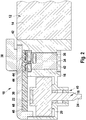
- Fig. 2 an embodiment of the invention of the drive device 10 is shown in a sectional view.
- the drive device 10 likewise has a pole housing 12, in which a drive motor 14, for example an electric motor, is arranged.
- the pole housing 12 is in turn attached to a flange portion of a transmission housing 16.
- a transmission device 18 is arranged in the transmission housing 16.
- the transmission device 18 a gear wheel 20 and gear with a magnetic element or encoder magnet 22 on.
- Via a drive shaft 24 connected to the gear wheel 20 further devices can be driven, for example a wiper system, such as a front or rear wiper system of a vehicle.
- the drive shaft 24 is rotatably mounted in the transmission housing 16 via a bearing assembly 40, for example consisting of two rolling bearings.
- the gear mechanism 18 or the gear wheel 20 is driven via an armature shaft 28 of the drive motor 14.
- a brush holder 34 is arranged with its brush elements in the transmission housing 16.
- the brush elements in this case interact with a commutator (not shown) of the drive motor 14.
- the gear housing 16 is made of metal or a metal alloy and may be made for example in the form of a metal casting.
- the gear housing 16 has a housing for accommodating the brush holder 34 and its brush elements corresponding receptacle 36 or depression.
- the gear housing 16 may be formed open on the top and / or bottom in the region of the receptacle 36 for the brush holder 34 and the brush elements, for introducing these elements.
- This open area can be formed coverable, for example, each with a cover 42, here a cover plate, for example made of metal or a metal alloy.
- a cover plate 42 made of metal or a metal alloy.
- the metallic gear housing 16 and the metallic receptacle 36 for the brush elements and their holder 34, as well as by the provision of metallic cover plates 42 a kind of Faraday cage for the brush assembly can be provided.
- at least one or more electrical components 44 for example interference suppression elements, may be provided.
- a suppression element 44 for example, a feedthrough capacitor Duko can be used.
- the brush holder 34 may be provided with at least one or more so-called. EMC components, and optionally with at least one additional connector or socket connection.
- EMC components for example, throttles, capacitors, etc. may be provided.
- the transmission housing 16 is closed with a gear cover 30, as in Fig. 2 is shown.
- a receptacle 46 for a printed circuit board 48 may be provided on the inside of the gear cover 30.
- the circuit board 48 can In this case, for example, have the control electronics or parts of the control electronics for the drive motor 14.
- On the circuit board 48 in addition to or instead of the control electronics further electrical components 44, such as capacitors, coils, relays and transistors, such as power transistors, be arranged, and sliding contact elements or optoelectronic devices, etc.
- the present invention is based on said elements 44 inclusive the electronics for the drive motor 14 is not limited, but the elements are merely examples that can be provided on the circuit board 48.
- the gear cover 30 may also have a plug connection 38 or socket connection on its outer side.
- the gear cover 30 may also consist of metal or a metal alloy or have this. In principle, the gear cover 30 may also be made of plastic or at least parts thereof.
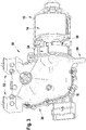
- a drive device 10 is shown as a further example, not part of the claimed invention.
- the pole housing 12 of the drive device 10 is shown transparent.
- a drive motor 14 here an electric motor, is arranged.
- a brush holder 34 and its brush elements are arranged in the pole housing 12.
- a frame or shell 50 of a stator forms a Faraday cage around the brush holder 34 and its brush elements.
- the jacket 50 is made of metal or a metal alloy or of sheet metal and shields the brush holder 34 and the brush holder elements to the outside.
- the pole housing 12 is, as in Fig. 3 shown attached to a flange of a transmission housing 16, for example by means of screws.
- a transmission device (not shown) is arranged, as for example with reference to Fig. 1 and 2 previously described.
- the transmission device which has, for example, a gear wheel, a transmitter magnet and a drive shaft, is driven via an armature shaft of the drive motor 14.
- the gear housing 16 is closed by means of a gear cover 30.
- the gear cover 30 has on its outside, for example, a receptacle 52 for attachment in a vehicle, and a breakpoint 54, for additional fixing or positioning of the drive device 10 in a vehicle.
- the gear cover is removed.
- a sealing rubber element 56 is attached or inserted to protect the gear housing 16 from contamination.
- the brush holder and its brush elements are arranged in the pole housing and not in the transmission housing 16, as previously with reference to FIG Fig. 1 and 2 has been described, the transmission housing 16 can be made more compact.
- the invention provides, inter alia, to use the space around the brush holder in addition functionally, so that the overall structure of the drive device or the engine can be reduced.
- the space around the brush holder used for supporting and cooling a printed circuit board and / or as a direct outlet for a plug, as with respect to the Fig. 1 and 2 has been described.
- a simple metallic cover element or a metallic cover plate can be used to shield the brush holder area in the form of a kind of Faraday cage.
- the advantage of the invention lies in the fact that the space around the brush holder can be used by, for example, a printed circuit board is placed at least partially or completely over it.
- a cooling surface for the printed circuit board can be provided with an additional metal cover plate.
- a plug outlet can also be placed directly in the installation space around the brush holder.
- Another advantage of the invention is that a metallic shield of the brush holder portion is provided to form a type of Faraday cage. As a result, increased customer requirements can be achieved by the brush holder portion is shielded against the radiation, for example, radio frequencies or digital radio frequencies.
- Another advantage of the invention lies in the short connection paths of the brush elements or brushes, the Entstörimplantationn and the circuit board or the plug. By way of example, feed-through capacitors can be integrated in the respective cover element as suppressive elements. As a result, the space can be better utilized and thereby the space to be reduced in total.
Landscapes
- Engineering & Computer Science (AREA)
- Power Engineering (AREA)
- Physics & Mathematics (AREA)
- Electromagnetism (AREA)
- Mechanical Engineering (AREA)
- Motor Or Generator Frames (AREA)
- Connection Of Motors, Electrical Generators, Mechanical Devices, And The Like (AREA)
- Dc Machiner (AREA)
Priority Applications (1)
| Application Number | Priority Date | Filing Date | Title |
|---|---|---|---|
| PL09734806T PL2272154T3 (pl) | 2008-04-24 | 2009-04-22 | Urządzenie napędowe zespołów pojazdu |
Applications Claiming Priority (2)
| Application Number | Priority Date | Filing Date | Title |
|---|---|---|---|
| DE102008001359A DE102008001359A1 (de) | 2008-04-24 | 2008-04-24 | Antriebsvorrichtung von Fahrzeugaggregaten |
| PCT/EP2009/054832 WO2009130249A1 (de) | 2008-04-24 | 2009-04-22 | Antriebsvorrichtung von fahrzeugaggregaten |
Publications (2)
| Publication Number | Publication Date |
|---|---|
| EP2272154A1 EP2272154A1 (de) | 2011-01-12 |
| EP2272154B1 true EP2272154B1 (de) | 2019-01-16 |
Family
ID=41038141
Family Applications (1)
| Application Number | Title | Priority Date | Filing Date |
|---|---|---|---|
| EP09734806.4A Active EP2272154B1 (de) | 2008-04-24 | 2009-04-22 | Antriebsvorrichtung von fahrzeugaggregaten |
Country Status (9)
| Country | Link |
|---|---|
| US (1) | US8410651B2 (pl) |
| EP (1) | EP2272154B1 (pl) |
| JP (1) | JP2011519257A (pl) |
| KR (1) | KR101684331B1 (pl) |
| DE (1) | DE102008001359A1 (pl) |
| ES (1) | ES2720177T3 (pl) |
| HU (1) | HUE043771T2 (pl) |
| PL (1) | PL2272154T3 (pl) |
| WO (1) | WO2009130249A1 (pl) |
Families Citing this family (23)
| Publication number | Priority date | Publication date | Assignee | Title |
|---|---|---|---|---|
| WO2011013629A1 (ja) | 2009-07-30 | 2011-02-03 | 株式会社ミツバ | 減速機構付きモータ |
| US10320265B2 (en) | 2009-07-30 | 2019-06-11 | Mitsuba Corporation | Wiper motor |
| FR2965231B1 (fr) * | 2010-09-29 | 2014-05-09 | Valeo Systemes Dessuyage | Support d'un groupe electrique d'entrainement d'un systeme d'essuyage, comprenant un dissipateur thermique |
| US9457768B2 (en) | 2011-04-21 | 2016-10-04 | Pylon Manufacturing Corp. | Vortex damping wiper blade |
| CA2843527C (en) | 2011-07-28 | 2018-11-27 | Pylon Manufacturing Corp. | Windshield wiper adapter, connector and assembly |
| US9108595B2 (en) | 2011-07-29 | 2015-08-18 | Pylon Manufacturing Corporation | Windshield wiper connector |
| DE102012100054A1 (de) | 2012-01-04 | 2013-07-04 | Hella Kgaa Hueck & Co. | Stellantrieb |
| DE102012100776A1 (de) * | 2012-01-31 | 2013-08-01 | Valeo Systèmes d'Essuyage | Scheibenwischermotor |
| MX385411B (es) | 2012-02-24 | 2025-03-18 | Pylon Mfg Corp | Escobilla limpiaparabrisas. |
| US10723322B2 (en) | 2012-02-24 | 2020-07-28 | Pylon Manufacturing Corp. | Wiper blade with cover |
| US20130219649A1 (en) | 2012-02-24 | 2013-08-29 | Pylon Manufacturing Corp. | Wiper blade |
| DE102012108853A1 (de) | 2012-09-20 | 2014-03-20 | Hella Kgaa Hueck & Co. | Stellantrieb |
| US10829092B2 (en) | 2012-09-24 | 2020-11-10 | Pylon Manufacturing Corp. | Wiper blade with modular mounting base |
| US10166951B2 (en) | 2013-03-15 | 2019-01-01 | Pylon Manufacturing Corp. | Windshield wiper connector |
| US9505380B2 (en) | 2014-03-07 | 2016-11-29 | Pylon Manufacturing Corp. | Windshield wiper connector and assembly |
| US10363905B2 (en) | 2015-10-26 | 2019-07-30 | Pylon Manufacturing Corp. | Wiper blade |
| AU2017268008A1 (en) | 2016-05-19 | 2018-11-22 | Pylon Manufacturing Corp. | Windshield wiper connector |
| CN109311450A (zh) | 2016-05-19 | 2019-02-05 | 电缆塔制造有限公司 | 挡风玻璃雨刮器连接器 |
| CN109311452A (zh) | 2016-05-19 | 2019-02-05 | 电缆塔制造有限公司 | 挡风玻璃雨刮器连接器 |
| EP3458315B1 (en) | 2016-05-19 | 2021-09-08 | Pylon Manufacturing Corp. | Windshield wiper blade |
| US11040705B2 (en) | 2016-05-19 | 2021-06-22 | Pylon Manufacturing Corp. | Windshield wiper connector |
| DE102020205151A1 (de) | 2020-04-23 | 2021-10-28 | Robert Bosch Gesellschaft mit beschränkter Haftung | Antriebsvorrichtung für ein Fahrzeug und Fahrzeug |
| KR102658044B1 (ko) * | 2023-10-16 | 2024-04-17 | 지알디씨 주식회사 | 와이퍼 구동용 모터 및 이를 포함하는 와이퍼 어셈블리 |
Citations (1)
| Publication number | Priority date | Publication date | Assignee | Title |
|---|---|---|---|---|
| EP1251604A2 (en) * | 2001-04-19 | 2002-10-23 | Jidosha Denki Kogyo Kabushiki Kaisha | Brush for a commutator motor |
Family Cites Families (13)
| Publication number | Priority date | Publication date | Assignee | Title |
|---|---|---|---|---|
| DE3021948A1 (de) * | 1980-06-12 | 1981-12-24 | Rau Swf Autozubehoer | Elektrische antriebseinheit, insbesondere fuer scheibenwischer eines kraftfahrzeuges |
| DE3318362A1 (de) * | 1983-05-20 | 1984-11-22 | SWF Auto-Electric GmbH, 7120 Bietigheim-Bissingen | Elektromotor, insbesondere scheibenwischermotor |
| EP0471876B1 (de) * | 1990-08-23 | 1994-06-08 | Siemens Aktiengesellschaft | Motor-Getriebe-Antriebseinheit, insbesondere Kraftfahrzeug-Fensterheberantrieb |
| US5650676A (en) * | 1992-10-24 | 1997-07-22 | Licentia Patent-Verwaltungs-Gmbh | Electric motor with improved seal |
| DE19805185A1 (de) * | 1998-02-10 | 1999-08-12 | Bosch Gmbh Robert | Antriebsvorrichtung, insbesondere zum Verstellen eines Schiebedachs eines Fahrzeugs |
| DE19858233A1 (de) * | 1998-12-17 | 2000-06-29 | Bosch Gmbh Robert | Elektrischer Getriebemotor für Fahrzeugaggregate |
| DE19954966A1 (de) * | 1999-11-16 | 2001-06-07 | Bosch Gmbh Robert | Elektrische Antriebseinheit |
| JP2001268852A (ja) * | 2000-03-16 | 2001-09-28 | Asmo Co Ltd | モータ及びワイパ用モータ |
| JP3641238B2 (ja) * | 2001-12-26 | 2005-04-20 | アスモ株式会社 | ブラシ保持装置、回転電機の組み付け方法 |
| US6851509B2 (en) * | 2002-08-09 | 2005-02-08 | Denso Corporation | Easy-to-assemble structure of electric power steering device |
| JP3954527B2 (ja) * | 2003-05-30 | 2007-08-08 | アスモ株式会社 | ブラシホルダ装置及びモータ |
| JP4545428B2 (ja) * | 2003-12-16 | 2010-09-15 | 株式会社ミツバ | 電動モータ |
| JP4822770B2 (ja) * | 2005-08-29 | 2011-11-24 | 株式会社ミツバ | モータおよび二重ヨークを備えたモータの製造方法 |
-
2008
- 2008-04-24 DE DE102008001359A patent/DE102008001359A1/de not_active Ceased
-
2009
- 2009-04-22 PL PL09734806T patent/PL2272154T3/pl unknown
- 2009-04-22 WO PCT/EP2009/054832 patent/WO2009130249A1/de not_active Ceased
- 2009-04-22 KR KR1020107023630A patent/KR101684331B1/ko active Active
- 2009-04-22 HU HUE09734806A patent/HUE043771T2/hu unknown
- 2009-04-22 EP EP09734806.4A patent/EP2272154B1/de active Active
- 2009-04-22 JP JP2011505500A patent/JP2011519257A/ja active Pending
- 2009-04-22 US US12/743,404 patent/US8410651B2/en active Active
- 2009-04-22 ES ES09734806T patent/ES2720177T3/es active Active
Patent Citations (1)
| Publication number | Priority date | Publication date | Assignee | Title |
|---|---|---|---|---|
| EP1251604A2 (en) * | 2001-04-19 | 2002-10-23 | Jidosha Denki Kogyo Kabushiki Kaisha | Brush for a commutator motor |
Also Published As
| Publication number | Publication date |
|---|---|
| EP2272154A1 (de) | 2011-01-12 |
| DE102008001359A1 (de) | 2009-10-29 |
| KR101684331B1 (ko) | 2016-12-08 |
| US8410651B2 (en) | 2013-04-02 |
| KR20110008188A (ko) | 2011-01-26 |
| HUE043771T2 (hu) | 2019-09-30 |
| PL2272154T3 (pl) | 2019-07-31 |
| WO2009130249A1 (de) | 2009-10-29 |
| JP2011519257A (ja) | 2011-06-30 |
| ES2720177T3 (es) | 2019-07-18 |
| US20110030162A1 (en) | 2011-02-10 |
Similar Documents
| Publication | Publication Date | Title |
|---|---|---|
| EP2272154B1 (de) | Antriebsvorrichtung von fahrzeugaggregaten | |
| DE112012003286B4 (de) | Schwingfeste Struktur für eine elektrische Schaltung eines elektrischen Verdichters | |
| DE102007002836A1 (de) | Elektrischer Antrieb | |
| DE69601270T2 (de) | Getriebemotor, insbesondere zum Antrieb eines Kraftfahrzeug-Scheibenwischers | |
| DE102017208632A1 (de) | Kraftfahrzeug und Stromrichtereinrichtung für ein Kraftfahrzeug | |
| DE102016200103A1 (de) | Antriebsvorrichtung | |
| WO1995002916B1 (de) | Antriebsvorrichtung für ein verstellbares fahrzeugteil | |
| DE3318362A1 (de) | Elektromotor, insbesondere scheibenwischermotor | |
| DE102011113198A1 (de) | Querträger zur Befestigung einer elektrischen Maschine in einem Motorraum eines Fahrzeugs und Fahrzeug | |
| EP2224579B1 (de) | Kfz-Aggregat Elektromotor | |
| WO1998025799A1 (de) | Vorrichtung zur herstellung einer elektrischen steckverbindung zwischen elektrischen oder elektronischen bauteilen oder baugruppen | |
| EP2030309A1 (de) | Antriebseinrichtung mit einem elektromotor und einer ansteuerelektronik mit schaltungsträger | |
| DE10018230A1 (de) | Antrieb für ein verstellbares Fahrzeugteil | |
| DE10020017B4 (de) | Elektromechanische Antriebsvorrichtung | |
| DE102020204281A1 (de) | Schutzanordnung für zumindest eine elektrische Antriebsstrangkomponente für ein Fahrzeug | |
| DE102023104150A1 (de) | Motorvorrichtung | |
| DE102007007238A1 (de) | Antriebsvorrichtung, Kraftfahrzeug-Lüftungselement und Verfahren zur Herstellung einer Äquipotentialleitung in einer Abtriebsvorrichtung | |
| DE102006039280B4 (de) | Motor mit Steuerschaltungsteil | |
| EP1001509B1 (de) | Entstörter Kommutatormotor, insbesondere drehzahlstellbarer Kraftfahrzeug-Servomotor | |
| DE102011084505A1 (de) | Lenksystem in einem Fahrzeug | |
| DE19717909C2 (de) | Elektrisches Gerät | |
| DE102011084507A1 (de) | Lenksystem in einem Fahrzeug | |
| DE102023201441A1 (de) | Antriebsvorrichtung für ein elektrisch betriebenes Fahrzeug | |
| WO2021089498A1 (de) | Antriebsvorrichtung für verstelleinrichtungen von kraftfahrzeugen mit einem wenigstens zweiteiligen gehäuse sowie verfahren zur montage einer solchen antriebsvorrichtung | |
| DE102023107720A1 (de) | Ladeschnittstelle für ein fahrzeug |
Legal Events
| Date | Code | Title | Description |
|---|---|---|---|
| PUAI | Public reference made under article 153(3) epc to a published international application that has entered the european phase |
Free format text: ORIGINAL CODE: 0009012 |
|
| 17P | Request for examination filed |
Effective date: 20101124 |
|
| AK | Designated contracting states |
Kind code of ref document: A1 Designated state(s): AT BE BG CH CY CZ DE DK EE ES FI FR GB GR HR HU IE IS IT LI LT LU LV MC MK MT NL NO PL PT RO SE SI SK TR |
|
| AX | Request for extension of the european patent |
Extension state: AL BA RS |
|
| DAX | Request for extension of the european patent (deleted) | ||
| 17Q | First examination report despatched |
Effective date: 20160818 |
|
| STAA | Information on the status of an ep patent application or granted ep patent |
Free format text: STATUS: EXAMINATION IS IN PROGRESS |
|
| GRAP | Despatch of communication of intention to grant a patent |
Free format text: ORIGINAL CODE: EPIDOSNIGR1 |
|
| STAA | Information on the status of an ep patent application or granted ep patent |
Free format text: STATUS: GRANT OF PATENT IS INTENDED |
|
| INTG | Intention to grant announced |
Effective date: 20180913 |
|
| GRAS | Grant fee paid |
Free format text: ORIGINAL CODE: EPIDOSNIGR3 |
|
| GRAA | (expected) grant |
Free format text: ORIGINAL CODE: 0009210 |
|
| STAA | Information on the status of an ep patent application or granted ep patent |
Free format text: STATUS: THE PATENT HAS BEEN GRANTED |
|
| AK | Designated contracting states |
Kind code of ref document: B1 Designated state(s): AT BE BG CH CY CZ DE DK EE ES FI FR GB GR HR HU IE IS IT LI LT LU LV MC MK MT NL NO PL PT RO SE SI SK TR |
|
| REG | Reference to a national code |
Ref country code: GB Ref legal event code: FG4D Free format text: NOT ENGLISH |
|
| REG | Reference to a national code |
Ref country code: CH Ref legal event code: EP |
|
| REG | Reference to a national code |
Ref country code: IE Ref legal event code: FG4D Free format text: LANGUAGE OF EP DOCUMENT: GERMAN |
|
| REG | Reference to a national code |
Ref country code: AT Ref legal event code: REF Ref document number: 1090446 Country of ref document: AT Kind code of ref document: T Effective date: 20190215 |
|
| REG | Reference to a national code |
Ref country code: DE Ref legal event code: R096 Ref document number: 502009015579 Country of ref document: DE |
|
| REG | Reference to a national code |
Ref country code: NL Ref legal event code: MP Effective date: 20190116 |
|
| REG | Reference to a national code |
Ref country code: LT Ref legal event code: MG4D |
|
| PG25 | Lapsed in a contracting state [announced via postgrant information from national office to epo] |
Ref country code: NL Free format text: LAPSE BECAUSE OF FAILURE TO SUBMIT A TRANSLATION OF THE DESCRIPTION OR TO PAY THE FEE WITHIN THE PRESCRIBED TIME-LIMIT Effective date: 20190116 |
|
| REG | Reference to a national code |
Ref country code: ES Ref legal event code: FG2A Ref document number: 2720177 Country of ref document: ES Kind code of ref document: T3 Effective date: 20190718 |
|
| PG25 | Lapsed in a contracting state [announced via postgrant information from national office to epo] |
Ref country code: SE Free format text: LAPSE BECAUSE OF FAILURE TO SUBMIT A TRANSLATION OF THE DESCRIPTION OR TO PAY THE FEE WITHIN THE PRESCRIBED TIME-LIMIT Effective date: 20190116 Ref country code: NO Free format text: LAPSE BECAUSE OF FAILURE TO SUBMIT A TRANSLATION OF THE DESCRIPTION OR TO PAY THE FEE WITHIN THE PRESCRIBED TIME-LIMIT Effective date: 20190416 Ref country code: PT Free format text: LAPSE BECAUSE OF FAILURE TO SUBMIT A TRANSLATION OF THE DESCRIPTION OR TO PAY THE FEE WITHIN THE PRESCRIBED TIME-LIMIT Effective date: 20190516 Ref country code: FI Free format text: LAPSE BECAUSE OF FAILURE TO SUBMIT A TRANSLATION OF THE DESCRIPTION OR TO PAY THE FEE WITHIN THE PRESCRIBED TIME-LIMIT Effective date: 20190116 Ref country code: LT Free format text: LAPSE BECAUSE OF FAILURE TO SUBMIT A TRANSLATION OF THE DESCRIPTION OR TO PAY THE FEE WITHIN THE PRESCRIBED TIME-LIMIT Effective date: 20190116 |
|
| PG25 | Lapsed in a contracting state [announced via postgrant information from national office to epo] |
Ref country code: IS Free format text: LAPSE BECAUSE OF FAILURE TO SUBMIT A TRANSLATION OF THE DESCRIPTION OR TO PAY THE FEE WITHIN THE PRESCRIBED TIME-LIMIT Effective date: 20190516 Ref country code: GR Free format text: LAPSE BECAUSE OF FAILURE TO SUBMIT A TRANSLATION OF THE DESCRIPTION OR TO PAY THE FEE WITHIN THE PRESCRIBED TIME-LIMIT Effective date: 20190417 Ref country code: HR Free format text: LAPSE BECAUSE OF FAILURE TO SUBMIT A TRANSLATION OF THE DESCRIPTION OR TO PAY THE FEE WITHIN THE PRESCRIBED TIME-LIMIT Effective date: 20190116 Ref country code: LV Free format text: LAPSE BECAUSE OF FAILURE TO SUBMIT A TRANSLATION OF THE DESCRIPTION OR TO PAY THE FEE WITHIN THE PRESCRIBED TIME-LIMIT Effective date: 20190116 Ref country code: BG Free format text: LAPSE BECAUSE OF FAILURE TO SUBMIT A TRANSLATION OF THE DESCRIPTION OR TO PAY THE FEE WITHIN THE PRESCRIBED TIME-LIMIT Effective date: 20190416 |
|
| REG | Reference to a national code |
Ref country code: HU Ref legal event code: AG4A Ref document number: E043771 Country of ref document: HU |
|
| REG | Reference to a national code |
Ref country code: DE Ref legal event code: R097 Ref document number: 502009015579 Country of ref document: DE |
|
| PG25 | Lapsed in a contracting state [announced via postgrant information from national office to epo] |
Ref country code: RO Free format text: LAPSE BECAUSE OF FAILURE TO SUBMIT A TRANSLATION OF THE DESCRIPTION OR TO PAY THE FEE WITHIN THE PRESCRIBED TIME-LIMIT Effective date: 20190116 Ref country code: EE Free format text: LAPSE BECAUSE OF FAILURE TO SUBMIT A TRANSLATION OF THE DESCRIPTION OR TO PAY THE FEE WITHIN THE PRESCRIBED TIME-LIMIT Effective date: 20190116 Ref country code: DK Free format text: LAPSE BECAUSE OF FAILURE TO SUBMIT A TRANSLATION OF THE DESCRIPTION OR TO PAY THE FEE WITHIN THE PRESCRIBED TIME-LIMIT Effective date: 20190116 Ref country code: SK Free format text: LAPSE BECAUSE OF FAILURE TO SUBMIT A TRANSLATION OF THE DESCRIPTION OR TO PAY THE FEE WITHIN THE PRESCRIBED TIME-LIMIT Effective date: 20190116 |
|
| PLBE | No opposition filed within time limit |
Free format text: ORIGINAL CODE: 0009261 |
|
| STAA | Information on the status of an ep patent application or granted ep patent |
Free format text: STATUS: NO OPPOSITION FILED WITHIN TIME LIMIT |
|
| REG | Reference to a national code |
Ref country code: CH Ref legal event code: PL |
|
| REG | Reference to a national code |
Ref country code: BE Ref legal event code: MM Effective date: 20190430 |
|
| 26N | No opposition filed |
Effective date: 20191017 |
|
| GBPC | Gb: european patent ceased through non-payment of renewal fee |
Effective date: 20190422 |
|
| PG25 | Lapsed in a contracting state [announced via postgrant information from national office to epo] |
Ref country code: LU Free format text: LAPSE BECAUSE OF NON-PAYMENT OF DUE FEES Effective date: 20190422 Ref country code: MC Free format text: LAPSE BECAUSE OF FAILURE TO SUBMIT A TRANSLATION OF THE DESCRIPTION OR TO PAY THE FEE WITHIN THE PRESCRIBED TIME-LIMIT Effective date: 20190116 |
|
| PG25 | Lapsed in a contracting state [announced via postgrant information from national office to epo] |
Ref country code: CH Free format text: LAPSE BECAUSE OF NON-PAYMENT OF DUE FEES Effective date: 20190430 Ref country code: LI Free format text: LAPSE BECAUSE OF NON-PAYMENT OF DUE FEES Effective date: 20190430 Ref country code: GB Free format text: LAPSE BECAUSE OF NON-PAYMENT OF DUE FEES Effective date: 20190422 |
|
| PG25 | Lapsed in a contracting state [announced via postgrant information from national office to epo] |
Ref country code: BE Free format text: LAPSE BECAUSE OF NON-PAYMENT OF DUE FEES Effective date: 20190430 Ref country code: SI Free format text: LAPSE BECAUSE OF FAILURE TO SUBMIT A TRANSLATION OF THE DESCRIPTION OR TO PAY THE FEE WITHIN THE PRESCRIBED TIME-LIMIT Effective date: 20190116 |
|
| PG25 | Lapsed in a contracting state [announced via postgrant information from national office to epo] |
Ref country code: TR Free format text: LAPSE BECAUSE OF FAILURE TO SUBMIT A TRANSLATION OF THE DESCRIPTION OR TO PAY THE FEE WITHIN THE PRESCRIBED TIME-LIMIT Effective date: 20190116 |
|
| PG25 | Lapsed in a contracting state [announced via postgrant information from national office to epo] |
Ref country code: IE Free format text: LAPSE BECAUSE OF NON-PAYMENT OF DUE FEES Effective date: 20190422 |
|
| REG | Reference to a national code |
Ref country code: AT Ref legal event code: MM01 Ref document number: 1090446 Country of ref document: AT Kind code of ref document: T Effective date: 20190422 |
|
| PG25 | Lapsed in a contracting state [announced via postgrant information from national office to epo] |
Ref country code: AT Free format text: LAPSE BECAUSE OF NON-PAYMENT OF DUE FEES Effective date: 20190422 |
|
| PG25 | Lapsed in a contracting state [announced via postgrant information from national office to epo] |
Ref country code: CY Free format text: LAPSE BECAUSE OF FAILURE TO SUBMIT A TRANSLATION OF THE DESCRIPTION OR TO PAY THE FEE WITHIN THE PRESCRIBED TIME-LIMIT Effective date: 20190116 |
|
| PG25 | Lapsed in a contracting state [announced via postgrant information from national office to epo] |
Ref country code: MT Free format text: LAPSE BECAUSE OF FAILURE TO SUBMIT A TRANSLATION OF THE DESCRIPTION OR TO PAY THE FEE WITHIN THE PRESCRIBED TIME-LIMIT Effective date: 20190116 |
|
| PG25 | Lapsed in a contracting state [announced via postgrant information from national office to epo] |
Ref country code: MK Free format text: LAPSE BECAUSE OF FAILURE TO SUBMIT A TRANSLATION OF THE DESCRIPTION OR TO PAY THE FEE WITHIN THE PRESCRIBED TIME-LIMIT Effective date: 20190116 |
|
| PGFP | Annual fee paid to national office [announced via postgrant information from national office to epo] |
Ref country code: PL Payment date: 20250410 Year of fee payment: 17 Ref country code: DE Payment date: 20250624 Year of fee payment: 17 |
|
| PGFP | Annual fee paid to national office [announced via postgrant information from national office to epo] |
Ref country code: ES Payment date: 20250519 Year of fee payment: 17 |
|
| PGFP | Annual fee paid to national office [announced via postgrant information from national office to epo] |
Ref country code: HU Payment date: 20250423 Year of fee payment: 17 |
|
| PGFP | Annual fee paid to national office [announced via postgrant information from national office to epo] |
Ref country code: IT Payment date: 20250430 Year of fee payment: 17 |
|
| PGFP | Annual fee paid to national office [announced via postgrant information from national office to epo] |
Ref country code: FR Payment date: 20250422 Year of fee payment: 17 |
|
| PGFP | Annual fee paid to national office [announced via postgrant information from national office to epo] |
Ref country code: CZ Payment date: 20250409 Year of fee payment: 17 |