EP2272142B1 - Schaltschrank mit einer Bodenplatte - Google Patents
Schaltschrank mit einer Bodenplatte Download PDFInfo
- Publication number
- EP2272142B1 EP2272142B1 EP09717220.9A EP09717220A EP2272142B1 EP 2272142 B1 EP2272142 B1 EP 2272142B1 EP 09717220 A EP09717220 A EP 09717220A EP 2272142 B1 EP2272142 B1 EP 2272142B1
- Authority
- EP
- European Patent Office
- Prior art keywords
- plate
- electrical cabinet
- cable
- guide rods
- frame
- Prior art date
- Legal status (The legal status is an assumption and is not a legal conclusion. Google has not performed a legal analysis and makes no representation as to the accuracy of the status listed.)
- Active
Links
- 238000007789 sealing Methods 0.000 claims description 46
- 238000009826 distribution Methods 0.000 claims description 28
- 238000000926 separation method Methods 0.000 claims description 10
- NJPPVKZQTLUDBO-UHFFFAOYSA-N novaluron Chemical compound C1=C(Cl)C(OC(F)(F)C(OC(F)(F)F)F)=CC=C1NC(=O)NC(=O)C1=C(F)C=CC=C1F NJPPVKZQTLUDBO-UHFFFAOYSA-N 0.000 claims description 6
- 238000000034 method Methods 0.000 claims description 3
- 239000013013 elastic material Substances 0.000 claims description 2
- 229920001821 foam rubber Polymers 0.000 claims 1
- 239000000463 material Substances 0.000 description 4
- 230000008439 repair process Effects 0.000 description 4
- 230000006835 compression Effects 0.000 description 3
- 238000007906 compression Methods 0.000 description 3
- 230000000694 effects Effects 0.000 description 2
- 239000006260 foam Substances 0.000 description 2
- 238000009434 installation Methods 0.000 description 2
- 230000035515 penetration Effects 0.000 description 2
- 239000002131 composite material Substances 0.000 description 1
- 230000005494 condensation Effects 0.000 description 1
- 238000009833 condensation Methods 0.000 description 1
- 238000010276 construction Methods 0.000 description 1
- 230000001419 dependent effect Effects 0.000 description 1
- 238000006073 displacement reaction Methods 0.000 description 1
- 238000005516 engineering process Methods 0.000 description 1
- 238000004519 manufacturing process Methods 0.000 description 1
- 239000002184 metal Substances 0.000 description 1
- 230000000149 penetrating effect Effects 0.000 description 1
- 239000011148 porous material Substances 0.000 description 1
- 230000036316 preload Effects 0.000 description 1
- 238000003825 pressing Methods 0.000 description 1
- 230000001681 protective effect Effects 0.000 description 1
- XLYOFNOQVPJJNP-UHFFFAOYSA-N water Substances O XLYOFNOQVPJJNP-UHFFFAOYSA-N 0.000 description 1
Images



Classifications
-
- H—ELECTRICITY
- H02—GENERATION; CONVERSION OR DISTRIBUTION OF ELECTRIC POWER
- H02B—BOARDS, SUBSTATIONS OR SWITCHING ARRANGEMENTS FOR THE SUPPLY OR DISTRIBUTION OF ELECTRIC POWER
- H02B1/00—Frameworks, boards, panels, desks, casings; Details of substations or switching arrangements
- H02B1/26—Casings; Parts thereof or accessories therefor
- H02B1/30—Cabinet-type casings; Parts thereof or accessories therefor
- H02B1/305—Cable entries
-
- H—ELECTRICITY
- H02—GENERATION; CONVERSION OR DISTRIBUTION OF ELECTRIC POWER
- H02B—BOARDS, SUBSTATIONS OR SWITCHING ARRANGEMENTS FOR THE SUPPLY OR DISTRIBUTION OF ELECTRIC POWER
- H02B1/00—Frameworks, boards, panels, desks, casings; Details of substations or switching arrangements
- H02B1/26—Casings; Parts thereof or accessories therefor
- H02B1/50—Pedestal- or pad-mounted casings; Parts thereof or accessories therefor
-
- H—ELECTRICITY
- H02—GENERATION; CONVERSION OR DISTRIBUTION OF ELECTRIC POWER
- H02G—INSTALLATION OF ELECTRIC CABLES OR LINES, OR OF COMBINED OPTICAL AND ELECTRIC CABLES OR LINES
- H02G3/00—Installations of electric cables or lines or protective tubing therefor in or on buildings, equivalent structures or vehicles
- H02G3/22—Installations of cables or lines through walls, floors or ceilings, e.g. into buildings
-
- Y—GENERAL TAGGING OF NEW TECHNOLOGICAL DEVELOPMENTS; GENERAL TAGGING OF CROSS-SECTIONAL TECHNOLOGIES SPANNING OVER SEVERAL SECTIONS OF THE IPC; TECHNICAL SUBJECTS COVERED BY FORMER USPC CROSS-REFERENCE ART COLLECTIONS [XRACs] AND DIGESTS
- Y10—TECHNICAL SUBJECTS COVERED BY FORMER USPC
- Y10T—TECHNICAL SUBJECTS COVERED BY FORMER US CLASSIFICATION
- Y10T29/00—Metal working
- Y10T29/49—Method of mechanical manufacture
- Y10T29/49815—Disassembling
- Y10T29/49817—Disassembling with other than ancillary treating or assembling
-
- Y—GENERAL TAGGING OF NEW TECHNOLOGICAL DEVELOPMENTS; GENERAL TAGGING OF CROSS-SECTIONAL TECHNOLOGIES SPANNING OVER SEVERAL SECTIONS OF THE IPC; TECHNICAL SUBJECTS COVERED BY FORMER USPC CROSS-REFERENCE ART COLLECTIONS [XRACs] AND DIGESTS
- Y10—TECHNICAL SUBJECTS COVERED BY FORMER USPC
- Y10T—TECHNICAL SUBJECTS COVERED BY FORMER US CLASSIFICATION
- Y10T29/00—Metal working
- Y10T29/49—Method of mechanical manufacture
- Y10T29/49826—Assembling or joining
- Y10T29/49947—Assembling or joining by applying separate fastener
- Y10T29/49963—Threaded fastener
Definitions
- the invention relates to a control cabinet with a bottom plate, as it is arranged in particular in cable distribution cabinets between the distribution space and the socket space as a separation, but can also be found in other electrical cabinets use.
- Cable distribution cabinets are used for example in communications technology to connect a variety of house connections with the underground cables.
- Such a cabinet is for example from the US 5202538 known.
- the housing of the control cabinet in which the distribution chamber with the clamping bars or other active electrical components is located on a hollow base, which extends at least partially into the ground, and through which the underground cables are introduced.
- these blocks are located with terminal strips in the front area, approximately in the front half, of the outline of the housing.
- the ground cables should therefore preferably pass through the bottom plate in the rear area to be led from there behind the terminal strips to the required height.
- the underground cables could also penetrate the bottom plate in the front area, but would then have to be bent backwards below the lowest terminal strip.
- the thickness of the underground cables of usually more than 4 cm and the corresponding rigidity, this is in principle difficult, but even more so in view of the cramped installation conditions the harder the farther down the mounting frame, the terminal strips begin, because the less high is for a deflection to the rear remaining space between the cable passage in the bottom plate and the lowest clamping rail.
- the housing usually consists of an inner frame composed of profiles along the edges, to which the outer planking of the housing is applied and this inner frame often extends over the border between the distributor space and the base area and down to the limit only horizontal cross struts to which the bottom plate can be attached, has.
- this half does not have to be completely removed, but can be brought by folding away from engagement with the cables leading upwards.
- this plate part can also be completely removed.
- the folding enabling hinge is a separable hinge, or the attachment of this plate member to the frame can be solved.
- the relative to the folding plate member other plate member is preferably only removed and is not hinged equipped, but may alternatively be additionally foldable.
- the folding mechanism is designed so that the hinged plate part can be folded down into the base area.
- the attachment is to be selected together with the dimensioning of the plate member so that when removing a removal of this plate member only down, in the base area, takes place.
- an opening is provided, which extends over the dividing line between the two plate parts, through which the cables extend upwards.
- the moisture seal against ingress of moisture up into the distribution space is avoided that is not used as usual cable grommets made of rubber material in the form of thin sheet of 1 mm to 3 mm thickness, but the opening is closed around the cable with help of sealing blocks of an elastic material, in particular foam, which has a sealing length, ie measured in the vertical cable direction at this point, of at least 30mm, better at least 50mm, better at least 70mm own.
- sealing blocks are preferably made of a closed-cell foam, so a foamed plastic to prevent the ingress of water into the individual pores and the forward penetration in this way.
- the cable passages are pre-cut in the sealing blocks, but the parts falling out that provide the cable passage, not completely removed, but the necessary ring cuts still have interruptions as connecting points. In this way, especially several concentric almost completed ring cuts for different cable diameters can be made. During assembly, the required ring cut is then completed and removed the corresponding core element.
- the ring cuts are not vertical, ie at right angles to the top and bottom of the seal block, but in contrast slightly inclined and form a truncated cone, which has its narrowest diameter at the top.
- the approaching from below moisture will have to overcome with increasing upward through this increasing bias more and more resistance and therefore ultimately can not penetrate into the distribution chamber.
- the cone angle will be between 1 ° and 10 °, preferably between 2 ° and 7 °.
- the ring sections additionally have an access cut from the freely accessible edge of the seal block to the ring cut, along which the seal block can be unfolded in order to be able to push it from the side onto the already mounted cable.
- the seal blocks are longitudinally separated and the cable passages are either completely received in one of the two block parts - with an access cut to the contact surface to the other block part - or they are in the middle of the dividing line, so that no access cut is necessary ,
- one of the two associated halves of a sealing block is then located with its rear side facing away from the contact surface on a longitudinal edge of the opening in the bottom plate, so on one of the two plate parts.
- the dividing line between the block parts is not a straight dividing line, but has extensions in one and / or other transverse direction and the other block part has a corresponding recess.
- the dividing line is viewed zigzag in plan view, preferably, the two block parts are designed identically.
- These guide bars extend from the longitudinal edge of the opening on the one plate member, in particular the hinged plate member, transversely in the opening in the plate plane or slightly offset parallel to the plate plane, and across the parting line and also over the opposite longitudinal edge of the opening , under the other plate part.
- These guide rods are arranged distributed over the longitudinal extent at regular intervals and in the sealing blocks are at the same distance corresponding, transversely extending through holes for attachment as a guide opening.
- a guide opening is provided in each seal block laterally near the end.
- the length of the opening in the bottom plate is exactly filled by a certain number of sealing blocks, wherein the sum of the sealing blocks with respect to the opening in the bottom plate in both the longitudinal and transverse direction should have oversize to achieve the desired bias in the mounted state.
- the number of guide rods is thus preferably twice the number of sealing blocks.
- the longitudinal edge of the opening is formed on the plate members as a vertically extending stop surface, the height of which corresponds at least to the height of the seal blocks and preferably at the lower end a projecting into the opening offset for placing the Having ends of the sealing blocks.
- the guide rods are mounted at about half the height of this stop surface.
- this is preferably effected not only by inserting the second plate member alone, but by a transversely biasable pressure member presses against the second plate member facing the longitudinal edge of the sealing blocks and extends over the entire length of the opening.
- This pressure bar is slidably mounted by means of oblong holes on the non-folding plate member, in particular the front plate member, and is penetrated by the free ends of the guide rods, on which an external thread is applied.
- the pressure bar can be pre-tensioned against the sealing blocks by means of threaded closures applied to these free ends, behind the pressure bar.
- the undamaged old or an exchanged new bottom plate in the two-part hinged design according to the invention is relatively easy to assemble by the rear, hinged plate part is first attached to the frame in the not yet disguised base area below the mounting plane of the bottom plate.
- this plate member is folded up into the activated horizontal position and thereby introduced the cable through the access cut in their respective cable passage of the corresponding block member and fixed the rear plate member in this folded-up position.
- the second, front halves of the block parts are pushed onto the guide rods of the rear plate part, after again in the corresponding locations and with the appropriate diameter, the cable openings were opened for the cables lying further forward, which pass through the access cuts in their cable passages.
- the second plate part is brought from below through the base area from the front against the block parts, raised to the mounting plane of the bottom plate, and fixed relative to the frame.
- a compression bar extending over the entire length of the opening, which has a vertical leg extending downwardly from the front plate part, is pressed against the end face of the second row of blocks the on the guided and equipped with an external thread free end of the guide rods are applied to the screw caps.
- this is a model with a frame supporting the housing, or even without such a frame in which only a support frame for supporting the internals is present.
- a bottom plate may or may not be present.
- the housing ie the outer paneling and optionally the inner frame, must first be removed.
- the mounting of the bottom plate can be done and - if on the old frame still a bottom plate was present, which did not have to be removed to remove the old housing - the new plate is mounted below the level of the old base plate, whereby the new base plate and only the must surround the cable running down to the top and no further, from the old cabinet originating, vertical struts.
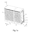
- FIG. 1 shows a cabinet 1 in the special design of a cable distribution cabinet KVS, as it is used in public space to accommodate home connections for telecommunications lines and the like in large numbers.
- this frame 7 has a transverse strut 7a at the level of the separation between the upper distributor space 4 and the lower base area 3 of the interior of the cabinet. Also in the longitudinal direction 10 - the larger extension of the cable distribution cabinet KVS considered in the plan view - the frame 7 has such a horizontal strut.
- the base portion 3 by removing the base panel 22 is accessible.
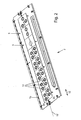
- a base plate 2 mounted there serves as a separation, which is fastened to the horizontal struts 7a of the frame 7 mounted on this height and is illustrated in FIGS. 2 and 3.
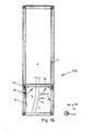
- FIG. 1b shows the frame 7 of the cable distribution cabinet KVS at the beginning of assembly of this bottom plate 2 when viewed in the longitudinal direction 10th
- the problem is that the brought out of the ground, usually several, cable 15 from below first pass through the base portion 3 and subsequently the parting plane to the distributor space 4, thus the bottom plate 2. This is just the Seal against bottom penetrating moisture between the base region 3 and manifold space 4 create and for this purpose seal the entire remaining horizontal space on this parting plane around the cable to the outer frame 7 out.
- the cables 15 should not be removed and it must be considered that the cables 15 are indeed relatively stiff, but are not completely fixed in their position, ie between the deadlock at its upper free end in the distribution chamber 4 and its exit point the ground at the bottom of the base area are still limited flexibility, which makes the sealing around these cables 15 around, especially over long periods, very difficult, because even by alone Weather-related and thus temperature-induced material strains, these cables shift their position, for example, between measurable distances between summer and winter seasons or day and night.
- the opening 9 is completely filled in the mounted state of cable sealing blocks 5, in which cable passages 12 can be opened through which, if necessary, a cable 15 is guided so that the outer periphery of the cable 15, not shown, the inner periphery of the cable passage 12 of a seal block 5 is tight ,
- the bottom plate 2 is usually a sheet metal part. So that the fitter, from the front - as in FIG. 1 a visible - works after opening the doors on the cabinet, the bottom plate 2 z. B. dismantle and then reinstall, for example, because the entire housing 6 must be changed because of damage, he is this work to work with the bottom plate 2 primarily only the base portion 3 available, which is essentially empty except for the lead-through cable 15.
- the distribution space 4 above it is - in contrast to the representation of FIG. 1b - filled in practice with a mounting frame on which a variety of electrical equipment is installed, which fill this space as far as possible.
- the plate part 2a can also be completely removed from the frame 7, either by the hinge 16 being a separable hinge or by the hinge 16 being inside the plate part 2a and the plate part 2a being screwed to the frame 7, in particular the part associated with the frame 7 of the hinge 16.
- the fitter facing the fitter front plate part 2 b is preferably not hingedly attached to the frame 7, but instead - as in FIG. 1b shown - from below, ie from the base area 3 ago, raised in the mounting position and connected there to the horizontal struts 7a of the frame 7.
- the plate parts 2a, b are sealed against each other and also relative to the frame, preferably by means of a seal placed therebetween.
- a zigzag-shaped parting line 5 ' is preferably selected, as illustrated on the block parts 5a, b, which effect a mutual centering of the block parts during compression in the transverse direction 11.
- the cable passages 12 may be disposed directly on the dividing line 5 'as shown in the blocks 5' and 5 ", or off the dividing line, respectively entirely in one of the block parts 5a, b, or both may be the case in a seal block, as shown at block 5 "'a, b.
- the front plate part 2b is inserted from below and fixed to the frame 7 at the level of the struts 7a.
- the size of the opening 9 in the transverse direction 11 is still somewhat larger than the width of the sealing blocks 5.
- this does not yet provide a reliable seal between the sealing blocks 5 and the base plate 2.
- a pressure bar 19 which extends in the longitudinal direction 10 over the entire length of the opening 9 and has an angled shape with a vertical and a horizontal leg in cross-section, optionally also has a second horizontal leg, has, against the leading edges of Sealing blocks 5 pressed.
- the pressure bar 19 is slidably mounted in the transverse direction 11 by engaging projecting from the plane of the plate pins of the plate member 2b extending in the transverse direction oblong holes of the pressure bar 19.
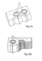
- an access cut 8 extends from the outer edge of the seal block 5 over the outer ring cuts 23b, c to the innermost ring cut 23a.
- the holding webs 25 in the individual ring sections are preferably present on the side opposite the access cut 8 in the ring section 23a, b, c.
- the good sealing effect is due, inter alia, that the sealing blocks 5 have a height of several centimeters and thus a large sealing length compared to the cable outer diameter.
- the ring sections 23 and the access section 8 extend not only over the entire height, ie thickness, of the sealing block 5, as in particular FIG. 4b and 4e but the circular one Ring cuts 23 do not form a cylindrical shape, but a cone shape in that they are inclined relative to the vertical center axis of the cable passage 12 by a cone angle of a few degrees.
Landscapes
- Engineering & Computer Science (AREA)
- Power Engineering (AREA)
- Patch Boards (AREA)
- Installation Of Indoor Wiring (AREA)
- Gasket Seals (AREA)
Priority Applications (1)
| Application Number | Priority Date | Filing Date | Title |
|---|---|---|---|
| PL09717220T PL2272142T3 (pl) | 2008-03-04 | 2009-03-03 | Szafa sterownicza dolną płytą |
Applications Claiming Priority (2)
| Application Number | Priority Date | Filing Date | Title |
|---|---|---|---|
| DE102008012460A DE102008012460C5 (de) | 2008-03-04 | 2008-03-04 | Bodenplatte oder Kabelverteilerschrank mit einer Bodenplatte und Montageverfahren |
| PCT/EP2009/052492 WO2009109568A1 (de) | 2008-03-04 | 2009-03-03 | Bodenplatte mit dichtungsblöcken |
Publications (2)
| Publication Number | Publication Date |
|---|---|
| EP2272142A1 EP2272142A1 (de) | 2011-01-12 |
| EP2272142B1 true EP2272142B1 (de) | 2014-05-07 |
Family
ID=40763590
Family Applications (1)
| Application Number | Title | Priority Date | Filing Date |
|---|---|---|---|
| EP09717220.9A Active EP2272142B1 (de) | 2008-03-04 | 2009-03-03 | Schaltschrank mit einer Bodenplatte |
Country Status (7)
| Country | Link |
|---|---|
| US (1) | US8541698B2 (pl) |
| EP (1) | EP2272142B1 (pl) |
| DE (1) | DE102008012460C5 (pl) |
| DK (1) | DK2272142T3 (pl) |
| IL (1) | IL205646A (pl) |
| PL (1) | PL2272142T3 (pl) |
| WO (1) | WO2009109568A1 (pl) |
Families Citing this family (28)
| Publication number | Priority date | Publication date | Assignee | Title |
|---|---|---|---|---|
| ES2394649T3 (es) | 2006-03-20 | 2013-02-04 | Beele Engineering B.V. | Sistema para sellar dinámicamente un manguito de canalización a través del cual se extiende un tubo o cable |
| ES2392791T3 (es) | 2010-05-25 | 2012-12-13 | Beele Engineering B.V. | Un conjunto y un procedimiento para proporcionar un sistema de sellado en una abertura |
| FR2963496B1 (fr) * | 2010-07-29 | 2013-06-28 | Areva T & D Sas | Installation de passage de cables pour poste de transformation electrique |
| US8664544B2 (en) * | 2010-07-29 | 2014-03-04 | Hydac Accessories Gmbh | Attachment system for cables, in particular for wind turbines |
| US20120048616A1 (en) * | 2010-08-25 | 2012-03-01 | Ideal Industries, Inc. | Grommet assembly |
| DE102010050964B3 (de) * | 2010-11-10 | 2012-02-16 | Berthold Sichert Gmbh | Unterflur-Schacht |
| DE102011004426A1 (de) | 2011-02-18 | 2012-08-23 | Schneider Electric Sachsenwerk Gmbh | Elektrische Schaltanlage, insbesondere Mittelspannungsschaltanlage |
| KR101241781B1 (ko) * | 2012-03-26 | 2013-03-15 | 한국 천문 연구원 | 진공 월-쓰루 구조물 |
| KR101275193B1 (ko) * | 2012-08-24 | 2013-07-03 | (주)동양이이씨 | 지중용 또는 지상형 개폐기 및 변압기의 야생동물 및 습기침투 방지용 차폐막 |
| ES2626753T3 (es) | 2012-08-30 | 2017-07-25 | Beele Engineering B.V. | Sistema de estanqueidad para un espacio anular |
| WO2014071021A1 (en) * | 2012-10-31 | 2014-05-08 | Adc Telecommunications, Inc. | Anchoring cables to rack with cable clamp arrangements |
| NL2010304C2 (en) * | 2013-02-14 | 2014-08-18 | Beele Eng Bv | System for sealingly holding cables which extend through an opening. |
| US9038967B2 (en) * | 2013-03-26 | 2015-05-26 | Solar Turbines Incorporated | Fluid line clamp |
| US9046194B2 (en) * | 2013-08-13 | 2015-06-02 | Specifiedtechnologies Inc. | Protective conduit for a structural panel opening |
| KR101606430B1 (ko) * | 2013-11-13 | 2016-03-25 | (주)동양이이씨 | 지상기기의 다목적 차폐장치 |
| DE202016103494U1 (de) * | 2016-06-30 | 2017-07-06 | Conta-Clip Verbindungstechnik Gmbh | Kabelwanddurchführung und Bausatz |
| CN106058670B (zh) * | 2016-07-06 | 2018-09-28 | 连云港市港圣开关制造有限公司 | 一种用于电力系统的智能配电柜 |
| WO2018158362A1 (en) * | 2017-03-01 | 2018-09-07 | CommScope Connectivity Belgium BVBA | Cable sealing unit with cable sealing modules |
| DE202017102147U1 (de) * | 2017-04-10 | 2017-05-05 | Igus Gmbh | Leitungsdurchführung, insbesondere Zugentlastung für eine Energieführungskette |
| EP3470717A1 (de) * | 2017-10-13 | 2019-04-17 | HILTI Aktiengesellschaft | Brandschutzvorrichtung |
| EP3470718A1 (de) * | 2017-10-13 | 2019-04-17 | HILTI Aktiengesellschaft | Brandschutzvorrichtung |
| US11452223B2 (en) | 2017-11-22 | 2022-09-20 | Telefonaktiebolaget Lm Ericsson (Publ) | Cable sealing assembly |
| DE102018207019A1 (de) * | 2018-05-07 | 2019-11-07 | Icotek Project Gmbh & Co. Kg | Wanddurchführung |
| CN110824646B (zh) * | 2019-12-01 | 2023-08-22 | 杭州昱华科技有限公司 | 一种防水防尘光缆交接箱 |
| US11211780B1 (en) * | 2020-09-14 | 2021-12-28 | Quanta Computer Inc. | Cable pass-through device |
| CN112401534A (zh) * | 2020-12-03 | 2021-02-26 | 湖南工学院 | 一种智能家居储物柜 |
| DE202020107214U1 (de) * | 2020-12-14 | 2021-01-15 | Rittal Gmbh & Co. Kg | Schaltschrankanordnung mit einer Kabeleinführung |
| CN113054558B (zh) * | 2021-03-30 | 2022-11-11 | 重庆诚衡电气设备有限公司 | 一种具有层状线路支护机构的电气柜 |
Citations (1)
| Publication number | Priority date | Publication date | Assignee | Title |
|---|---|---|---|---|
| FR2535914A1 (fr) * | 1982-11-05 | 1984-05-11 | Marandet Pierre | Obturateur d'une ouverture permettant le passage d'objets et application a l'obturation d'une ouverture traversable par des cables electriques ou optiques en nombre variable |
Family Cites Families (21)
| Publication number | Priority date | Publication date | Assignee | Title |
|---|---|---|---|---|
| DE2720936A1 (de) * | 1977-05-10 | 1978-11-23 | Ewald Nelken | Kabeleinfuehrung |
| DE7816729U1 (de) * | 1978-06-03 | 1978-09-28 | Rittal-Werk Rudolf Loh Gmbh & Co Kg, 6341 Rittershausen | Schaltschrank mit Bodenplatte |
| DE3205934C2 (de) * | 1982-02-19 | 1985-11-28 | Krone Gmbh, 1000 Berlin | Aus mehreren Bodenelementen zusammensetzbare Bodenplatte mit angeformten Seitenholmen für ein Kabelverzweigergehäuse |
| NL8403650A (nl) * | 1984-11-30 | 1986-06-16 | Johannes Alfred Beele | Doorvoerinrichting. |
| GB2186440B (en) * | 1986-02-11 | 1990-03-14 | Hawke Cable Glands Ltd | Improved transit for cables and pipes |
| DE8620941U1 (de) * | 1986-08-04 | 1986-11-20 | Thyssen Plastik Anger KG, 8000 München | Verbindungselement |
| US5202538A (en) * | 1990-03-20 | 1993-04-13 | Union Connector Co., Inc. | Portable power distribution cabinet |
| US6265670B1 (en) * | 1993-03-18 | 2001-07-24 | The Whitaker Corporation | Grommet for plurality of cable exits of an enclosure |
| DE4310117A1 (de) * | 1993-03-27 | 1994-09-29 | Heidelberger Druckmasch Ag | Vorrichtung zur Durchführung von Kabeln |
| US6396990B1 (en) * | 1998-06-12 | 2002-05-28 | Netrix Technologies, Inc. | Multi-purpose communications cabinet |
| DE29908044U1 (de) * | 1999-05-05 | 1999-07-29 | Paul Jordan Elektrotechnische Fabrik GmbH & Co., 12249 Berlin | Dichtungseinheit für Kabel- und Rohrdurchführungen |
| JP2002211848A (ja) | 2000-12-22 | 2002-07-31 | Inventio Ag | 昇降機のための制御ボックス |
| EP1376795B1 (de) * | 2002-06-21 | 2016-03-16 | icotek project GmbH & Co. KG | Vorrichtung zum Installieren von Energieleitungen |
| DE10307944B4 (de) | 2003-02-25 | 2005-08-18 | Berthold Sichert Gmbh | Überstülpbarer Verteilerschrank |
| US7282650B2 (en) * | 2004-10-14 | 2007-10-16 | Lockheed Martin Corp. | Conduit gland |
| US8051614B1 (en) * | 2005-06-21 | 2011-11-08 | Sprint Communications Company L.P. | Intumescent structure for ducting carrying communications cabling |
| DE102006033302A1 (de) | 2005-07-18 | 2007-02-22 | Almatec Ag | Staub- und/oder feuchtigkeitsdichte Kabeldurchführung |
| DE102006002478B4 (de) * | 2006-01-18 | 2008-05-15 | Berthold Sichert Gmbh | Bodenplatte sowie Kabelverteilerschrank mit Bodenplatte |
| US20080042536A1 (en) | 2006-08-21 | 2008-02-21 | Afl Telecommunications Llc. | Strain relief system |
| US7711234B2 (en) | 2006-10-02 | 2010-05-04 | Adc Telecommunications, Inc. | Reskinnable fiber distribution hub |
| US7330628B1 (en) | 2006-10-23 | 2008-02-12 | Adc Telecommunications, Inc. | Fiber access terminal including moisture barrier plate with punch out |
-
2008
- 2008-03-04 DE DE102008012460A patent/DE102008012460C5/de not_active Expired - Fee Related
-
2009
- 2009-03-03 PL PL09717220T patent/PL2272142T3/pl unknown
- 2009-03-03 WO PCT/EP2009/052492 patent/WO2009109568A1/de not_active Ceased
- 2009-03-03 DK DK09717220.9T patent/DK2272142T3/da active
- 2009-03-03 EP EP09717220.9A patent/EP2272142B1/de active Active
- 2009-03-03 US US12/921,040 patent/US8541698B2/en active Active
-
2010
- 2010-05-09 IL IL205646A patent/IL205646A/en active IP Right Grant
Patent Citations (1)
| Publication number | Priority date | Publication date | Assignee | Title |
|---|---|---|---|---|
| FR2535914A1 (fr) * | 1982-11-05 | 1984-05-11 | Marandet Pierre | Obturateur d'une ouverture permettant le passage d'objets et application a l'obturation d'une ouverture traversable par des cables electriques ou optiques en nombre variable |
Also Published As
| Publication number | Publication date |
|---|---|
| WO2009109568A1 (de) | 2009-09-11 |
| DE102008012460C5 (de) | 2013-04-25 |
| EP2272142A1 (de) | 2011-01-12 |
| DE102008012460B3 (de) | 2009-10-22 |
| PL2272142T3 (pl) | 2014-09-30 |
| IL205646A0 (en) | 2010-11-30 |
| WO2009109568A8 (de) | 2010-10-07 |
| US20110080078A1 (en) | 2011-04-07 |
| IL205646A (en) | 2016-03-31 |
| US8541698B2 (en) | 2013-09-24 |
| DK2272142T3 (da) | 2014-06-30 |
Similar Documents
| Publication | Publication Date | Title |
|---|---|---|
| DE102008012460C5 (de) | Bodenplatte oder Kabelverteilerschrank mit einer Bodenplatte und Montageverfahren | |
| DE102007012079B4 (de) | Verteilerschrank mit mehreren Innengehäusen | |
| DE102011012438B4 (de) | Baukasten für Befestigungsvorrichtung | |
| EP0404284B1 (de) | Gerüst für einen Schaltschrank aus mehrfach abgewinkelten Profilelementen | |
| DE69412563T2 (de) | Schrank mit Eckverbindung und ein Schaltschrank mit solchen Verbindungen | |
| EP0331690B1 (de) | Deckenverkleidung | |
| EP0415265A1 (de) | Vorrichtung zur Lagerung und zum Transport von Rohren | |
| DE4206682C2 (de) | Gehäuse, insbesondere Kabelverzweigergehäuse | |
| EP1811625A1 (de) | Bodenplatte sowie Kabelverteilerschrank mit Bodenplatte | |
| EP2596557A2 (de) | Rahmen für einen schrank, insbesondere für einen schaltschrank | |
| EP3091624A1 (de) | Installationsdose für elektrische geräte | |
| EP0651125B1 (de) | Verbindungsstück für winklig aneinanderstossende Rahmenstäbe | |
| EP0467066B1 (de) | Vorgehängte Fassade in Elementbauweise | |
| WO2007087829A1 (de) | Vorrichtung zum abtrennen von raumbereichen eines raumes | |
| DE102013105380A1 (de) | Dichtblock für Einzeladern | |
| DE102018101157A1 (de) | Schnellbauhalle, mit einer Eckverbindung zwischen Dach und Wand | |
| EP2878056B1 (de) | Unterirdischer schaltschrank für die elektroinstallation | |
| DE2717183C2 (de) | Installationskanal insbesondere zum Anbau an Büromöbel | |
| WO2007121762A1 (de) | Vorrichtung zum abtrennen von raumbereichen eines raums | |
| DE2654590C2 (de) | Gestell für elektrische Schaltanlagen | |
| DE20311022U1 (de) | Kabelkanal | |
| DE102017112011A1 (de) | Rahmen für ein Photovoltaik-Modul sowie Photovoltaik-System | |
| DE29706667U1 (de) | Rahmengestell für einen Schaltschrank | |
| DE102013003718B4 (de) | Leichtmetall-Gehäuse aus Eckprofilen und Wandelementen | |
| EP2653066A1 (de) | Stützbein für Arbeitsmöbel |
Legal Events
| Date | Code | Title | Description |
|---|---|---|---|
| PUAI | Public reference made under article 153(3) epc to a published international application that has entered the european phase |
Free format text: ORIGINAL CODE: 0009012 |
|
| 17P | Request for examination filed |
Effective date: 20101004 |
|
| AK | Designated contracting states |
Kind code of ref document: A1 Designated state(s): AT BE BG CH CY CZ DE DK EE ES FI FR GB GR HR HU IE IS IT LI LT LU LV MC MK MT NL NO PL PT RO SE SI SK TR |
|
| AX | Request for extension of the european patent |
Extension state: AL BA RS |
|
| RAX | Requested extension states of the european patent have changed |
Extension state: AL Payment date: 20101004 Extension state: BA Payment date: 20101004 Extension state: RS Payment date: 20101004 |
|
| RIN1 | Information on inventor provided before grant (corrected) |
Inventor name: PERSCHON, HELMUT Inventor name: IRMER, GUENTER |
|
| 17Q | First examination report despatched |
Effective date: 20130218 |
|
| GRAP | Despatch of communication of intention to grant a patent |
Free format text: ORIGINAL CODE: EPIDOSNIGR1 |
|
| INTG | Intention to grant announced |
Effective date: 20131127 |
|
| RAP1 | Party data changed (applicant data changed or rights of an application transferred) |
Owner name: BERTHOLD SICHERT GMBH |
|
| GRAS | Grant fee paid |
Free format text: ORIGINAL CODE: EPIDOSNIGR3 |
|
| GRAA | (expected) grant |
Free format text: ORIGINAL CODE: 0009210 |
|
| AK | Designated contracting states |
Kind code of ref document: B1 Designated state(s): AT BE BG CH CY CZ DE DK EE ES FI FR GB GR HR HU IE IS IT LI LT LU LV MC MK MT NL NO PL PT RO SE SI SK TR |
|
| AX | Request for extension of the european patent |
Extension state: AL BA RS |
|
| REG | Reference to a national code |
Ref country code: GB Ref legal event code: FG4D Free format text: NOT ENGLISH |
|
| REG | Reference to a national code |
Ref country code: AT Ref legal event code: REF Ref document number: 667324 Country of ref document: AT Kind code of ref document: T Effective date: 20140515 |
|
| REG | Reference to a national code |
Ref country code: IE Ref legal event code: FG4D Free format text: LANGUAGE OF EP DOCUMENT: GERMAN |
|
| REG | Reference to a national code |
Ref country code: DE Ref legal event code: R096 Ref document number: 502009009347 Country of ref document: DE Effective date: 20140618 |
|
| REG | Reference to a national code |
Ref country code: DK Ref legal event code: T3 Effective date: 20140623 |
|
| REG | Reference to a national code |
Ref country code: CH Ref legal event code: NV Representative=s name: SCHMAUDER AND PARTNER AG PATENT- UND MARKENANW, CH |
|
| REG | Reference to a national code |
Ref country code: NL Ref legal event code: T3 |
|
| REG | Reference to a national code |
Ref country code: PL Ref legal event code: T3 |
|
| REG | Reference to a national code |
Ref country code: NO Ref legal event code: T2 Effective date: 20140507 |
|
| REG | Reference to a national code |
Ref country code: LT Ref legal event code: MG4D |
|
| PG25 | Lapsed in a contracting state [announced via postgrant information from national office to epo] |
Ref country code: LT Free format text: LAPSE BECAUSE OF FAILURE TO SUBMIT A TRANSLATION OF THE DESCRIPTION OR TO PAY THE FEE WITHIN THE PRESCRIBED TIME-LIMIT Effective date: 20140507 Ref country code: CY Free format text: LAPSE BECAUSE OF FAILURE TO SUBMIT A TRANSLATION OF THE DESCRIPTION OR TO PAY THE FEE WITHIN THE PRESCRIBED TIME-LIMIT Effective date: 20140507 Ref country code: GR Free format text: LAPSE BECAUSE OF FAILURE TO SUBMIT A TRANSLATION OF THE DESCRIPTION OR TO PAY THE FEE WITHIN THE PRESCRIBED TIME-LIMIT Effective date: 20140808 Ref country code: FI Free format text: LAPSE BECAUSE OF FAILURE TO SUBMIT A TRANSLATION OF THE DESCRIPTION OR TO PAY THE FEE WITHIN THE PRESCRIBED TIME-LIMIT Effective date: 20140507 Ref country code: IS Free format text: LAPSE BECAUSE OF FAILURE TO SUBMIT A TRANSLATION OF THE DESCRIPTION OR TO PAY THE FEE WITHIN THE PRESCRIBED TIME-LIMIT Effective date: 20140907 |
|
| PG25 | Lapsed in a contracting state [announced via postgrant information from national office to epo] |
Ref country code: ES Free format text: LAPSE BECAUSE OF FAILURE TO SUBMIT A TRANSLATION OF THE DESCRIPTION OR TO PAY THE FEE WITHIN THE PRESCRIBED TIME-LIMIT Effective date: 20140507 Ref country code: SE Free format text: LAPSE BECAUSE OF FAILURE TO SUBMIT A TRANSLATION OF THE DESCRIPTION OR TO PAY THE FEE WITHIN THE PRESCRIBED TIME-LIMIT Effective date: 20140507 Ref country code: HR Free format text: LAPSE BECAUSE OF FAILURE TO SUBMIT A TRANSLATION OF THE DESCRIPTION OR TO PAY THE FEE WITHIN THE PRESCRIBED TIME-LIMIT Effective date: 20140507 Ref country code: LV Free format text: LAPSE BECAUSE OF FAILURE TO SUBMIT A TRANSLATION OF THE DESCRIPTION OR TO PAY THE FEE WITHIN THE PRESCRIBED TIME-LIMIT Effective date: 20140507 |
|
| PG25 | Lapsed in a contracting state [announced via postgrant information from national office to epo] |
Ref country code: PT Free format text: LAPSE BECAUSE OF FAILURE TO SUBMIT A TRANSLATION OF THE DESCRIPTION OR TO PAY THE FEE WITHIN THE PRESCRIBED TIME-LIMIT Effective date: 20140908 |
|
| PG25 | Lapsed in a contracting state [announced via postgrant information from national office to epo] |
Ref country code: RO Free format text: LAPSE BECAUSE OF FAILURE TO SUBMIT A TRANSLATION OF THE DESCRIPTION OR TO PAY THE FEE WITHIN THE PRESCRIBED TIME-LIMIT Effective date: 20140507 Ref country code: SK Free format text: LAPSE BECAUSE OF FAILURE TO SUBMIT A TRANSLATION OF THE DESCRIPTION OR TO PAY THE FEE WITHIN THE PRESCRIBED TIME-LIMIT Effective date: 20140507 Ref country code: EE Free format text: LAPSE BECAUSE OF FAILURE TO SUBMIT A TRANSLATION OF THE DESCRIPTION OR TO PAY THE FEE WITHIN THE PRESCRIBED TIME-LIMIT Effective date: 20140507 |
|
| REG | Reference to a national code |
Ref country code: DE Ref legal event code: R097 Ref document number: 502009009347 Country of ref document: DE |
|
| PLBE | No opposition filed within time limit |
Free format text: ORIGINAL CODE: 0009261 |
|
| STAA | Information on the status of an ep patent application or granted ep patent |
Free format text: STATUS: NO OPPOSITION FILED WITHIN TIME LIMIT |
|
| 26N | No opposition filed |
Effective date: 20150210 |
|
| PG25 | Lapsed in a contracting state [announced via postgrant information from national office to epo] |
Ref country code: IT Free format text: LAPSE BECAUSE OF FAILURE TO SUBMIT A TRANSLATION OF THE DESCRIPTION OR TO PAY THE FEE WITHIN THE PRESCRIBED TIME-LIMIT Effective date: 20140507 |
|
| REG | Reference to a national code |
Ref country code: DE Ref legal event code: R082 Ref document number: 502009009347 Country of ref document: DE Representative=s name: PATENTANWAELTE WEICKMANN & WEICKMANN, DE Ref country code: DE Ref legal event code: R082 Ref document number: 502009009347 Country of ref document: DE Representative=s name: WEICKMANN & WEICKMANN PATENTANWAELTE - RECHTSA, DE Ref country code: DE Ref legal event code: R082 Ref document number: 502009009347 Country of ref document: DE Representative=s name: WEICKMANN & WEICKMANN PATENT- UND RECHTSANWAEL, DE |
|
| REG | Reference to a national code |
Ref country code: DE Ref legal event code: R097 Ref document number: 502009009347 Country of ref document: DE Effective date: 20150210 |
|
| PG25 | Lapsed in a contracting state [announced via postgrant information from national office to epo] |
Ref country code: SI Free format text: LAPSE BECAUSE OF FAILURE TO SUBMIT A TRANSLATION OF THE DESCRIPTION OR TO PAY THE FEE WITHIN THE PRESCRIBED TIME-LIMIT Effective date: 20140507 |
|
| PG25 | Lapsed in a contracting state [announced via postgrant information from national office to epo] |
Ref country code: MC Free format text: LAPSE BECAUSE OF FAILURE TO SUBMIT A TRANSLATION OF THE DESCRIPTION OR TO PAY THE FEE WITHIN THE PRESCRIBED TIME-LIMIT Effective date: 20140507 Ref country code: LU Free format text: LAPSE BECAUSE OF FAILURE TO SUBMIT A TRANSLATION OF THE DESCRIPTION OR TO PAY THE FEE WITHIN THE PRESCRIBED TIME-LIMIT Effective date: 20150303 |
|
| REG | Reference to a national code |
Ref country code: IE Ref legal event code: MM4A |
|
| PG25 | Lapsed in a contracting state [announced via postgrant information from national office to epo] |
Ref country code: IE Free format text: LAPSE BECAUSE OF NON-PAYMENT OF DUE FEES Effective date: 20150303 |
|
| REG | Reference to a national code |
Ref country code: FR Ref legal event code: PLFP Year of fee payment: 8 |
|
| PG25 | Lapsed in a contracting state [announced via postgrant information from national office to epo] |
Ref country code: MT Free format text: LAPSE BECAUSE OF FAILURE TO SUBMIT A TRANSLATION OF THE DESCRIPTION OR TO PAY THE FEE WITHIN THE PRESCRIBED TIME-LIMIT Effective date: 20140507 |
|
| REG | Reference to a national code |
Ref country code: FR Ref legal event code: PLFP Year of fee payment: 9 |
|
| PG25 | Lapsed in a contracting state [announced via postgrant information from national office to epo] |
Ref country code: HU Free format text: LAPSE BECAUSE OF FAILURE TO SUBMIT A TRANSLATION OF THE DESCRIPTION OR TO PAY THE FEE WITHIN THE PRESCRIBED TIME-LIMIT; INVALID AB INITIO Effective date: 20090303 Ref country code: BG Free format text: LAPSE BECAUSE OF FAILURE TO SUBMIT A TRANSLATION OF THE DESCRIPTION OR TO PAY THE FEE WITHIN THE PRESCRIBED TIME-LIMIT Effective date: 20140507 |
|
| PG25 | Lapsed in a contracting state [announced via postgrant information from national office to epo] |
Ref country code: BE Free format text: LAPSE BECAUSE OF NON-PAYMENT OF DUE FEES Effective date: 20150331 |
|
| PG25 | Lapsed in a contracting state [announced via postgrant information from national office to epo] |
Ref country code: TR Free format text: LAPSE BECAUSE OF FAILURE TO SUBMIT A TRANSLATION OF THE DESCRIPTION OR TO PAY THE FEE WITHIN THE PRESCRIBED TIME-LIMIT Effective date: 20140507 |
|
| REG | Reference to a national code |
Ref country code: FR Ref legal event code: PLFP Year of fee payment: 10 |
|
| PG25 | Lapsed in a contracting state [announced via postgrant information from national office to epo] |
Ref country code: MK Free format text: LAPSE BECAUSE OF FAILURE TO SUBMIT A TRANSLATION OF THE DESCRIPTION OR TO PAY THE FEE WITHIN THE PRESCRIBED TIME-LIMIT Effective date: 20140507 |
|
| PGFP | Annual fee paid to national office [announced via postgrant information from national office to epo] |
Ref country code: DK Payment date: 20200323 Year of fee payment: 12 Ref country code: NO Payment date: 20200323 Year of fee payment: 12 Ref country code: NL Payment date: 20200323 Year of fee payment: 12 |
|
| PGFP | Annual fee paid to national office [announced via postgrant information from national office to epo] |
Ref country code: FR Payment date: 20200325 Year of fee payment: 12 |
|
| PGFP | Annual fee paid to national office [announced via postgrant information from national office to epo] |
Ref country code: CZ Payment date: 20210219 Year of fee payment: 13 Ref country code: CH Payment date: 20210324 Year of fee payment: 13 |
|
| PGFP | Annual fee paid to national office [announced via postgrant information from national office to epo] |
Ref country code: DE Payment date: 20210329 Year of fee payment: 13 Ref country code: GB Payment date: 20210324 Year of fee payment: 13 Ref country code: PL Payment date: 20210111 Year of fee payment: 13 Ref country code: AT Payment date: 20210318 Year of fee payment: 13 |
|
| REG | Reference to a national code |
Ref country code: NO Ref legal event code: MMEP |
|
| REG | Reference to a national code |
Ref country code: DK Ref legal event code: EBP Effective date: 20210331 |
|
| REG | Reference to a national code |
Ref country code: NL Ref legal event code: MM Effective date: 20210401 |
|
| PG25 | Lapsed in a contracting state [announced via postgrant information from national office to epo] |
Ref country code: FR Free format text: LAPSE BECAUSE OF NON-PAYMENT OF DUE FEES Effective date: 20210331 Ref country code: NO Free format text: LAPSE BECAUSE OF NON-PAYMENT OF DUE FEES Effective date: 20210331 Ref country code: NL Free format text: LAPSE BECAUSE OF NON-PAYMENT OF DUE FEES Effective date: 20210401 |
|
| PG25 | Lapsed in a contracting state [announced via postgrant information from national office to epo] |
Ref country code: DK Free format text: LAPSE BECAUSE OF NON-PAYMENT OF DUE FEES Effective date: 20210331 |
|
| REG | Reference to a national code |
Ref country code: DE Ref legal event code: R119 Ref document number: 502009009347 Country of ref document: DE |
|
| PG25 | Lapsed in a contracting state [announced via postgrant information from national office to epo] |
Ref country code: CZ Free format text: LAPSE BECAUSE OF NON-PAYMENT OF DUE FEES Effective date: 20220303 |
|
| REG | Reference to a national code |
Ref country code: CH Ref legal event code: PL |
|
| REG | Reference to a national code |
Ref country code: AT Ref legal event code: MM01 Ref document number: 667324 Country of ref document: AT Kind code of ref document: T Effective date: 20220303 |
|
| GBPC | Gb: european patent ceased through non-payment of renewal fee |
Effective date: 20220303 |
|
| PG25 | Lapsed in a contracting state [announced via postgrant information from national office to epo] |
Ref country code: LI Free format text: LAPSE BECAUSE OF NON-PAYMENT OF DUE FEES Effective date: 20220331 Ref country code: GB Free format text: LAPSE BECAUSE OF NON-PAYMENT OF DUE FEES Effective date: 20220303 Ref country code: DE Free format text: LAPSE BECAUSE OF NON-PAYMENT OF DUE FEES Effective date: 20221001 Ref country code: CH Free format text: LAPSE BECAUSE OF NON-PAYMENT OF DUE FEES Effective date: 20220331 Ref country code: AT Free format text: LAPSE BECAUSE OF NON-PAYMENT OF DUE FEES Effective date: 20220303 |
|
| P01 | Opt-out of the competence of the unified patent court (upc) registered |
Effective date: 20230526 |
|
| PG25 | Lapsed in a contracting state [announced via postgrant information from national office to epo] |
Ref country code: PL Free format text: LAPSE BECAUSE OF NON-PAYMENT OF DUE FEES Effective date: 20220303 |