EP2269934B1 - Aufhängungsplatte für einen aufzug und aufzugtürvorrichtung damit - Google Patents
Aufhängungsplatte für einen aufzug und aufzugtürvorrichtung damit Download PDFInfo
- Publication number
- EP2269934B1 EP2269934B1 EP09738951.4A EP09738951A EP2269934B1 EP 2269934 B1 EP2269934 B1 EP 2269934B1 EP 09738951 A EP09738951 A EP 09738951A EP 2269934 B1 EP2269934 B1 EP 2269934B1
- Authority
- EP
- European Patent Office
- Prior art keywords
- hanger
- hanger plate
- plate
- elevator
- elevator door
- Prior art date
- Legal status (The legal status is an assumption and is not a legal conclusion. Google has not performed a legal analysis and makes no representation as to the accuracy of the status listed.)
- Not-in-force
Links
Images


Classifications
-
- B—PERFORMING OPERATIONS; TRANSPORTING
- B66—HOISTING; LIFTING; HAULING
- B66B—ELEVATORS; ESCALATORS OR MOVING WALKWAYS
- B66B13/00—Doors, gates, or other apparatus controlling access to, or exit from, cages or lift well landings
- B66B13/02—Door or gate operation
-
- B—PERFORMING OPERATIONS; TRANSPORTING
- B66—HOISTING; LIFTING; HAULING
- B66B—ELEVATORS; ESCALATORS OR MOVING WALKWAYS
- B66B13/00—Doors, gates, or other apparatus controlling access to, or exit from, cages or lift well landings
- B66B13/02—Door or gate operation
- B66B13/06—Door or gate operation of sliding doors
- B66B13/08—Door or gate operation of sliding doors guided for horizontal movement
Definitions
- the present invention relates to a hanger plate for an elevator and an elevator door device including the same, and more particularly to a hanger plate for an elevator and an elevator door device including the same, which can prevent separation of en elevator door due to deformation of the hanger plate by increasing the rigidity of the hanger plate.
- the safety standard related to the separation of an elevator door due to an external impact is not quite satisfactory.
- EN European Nations
- a method of applying a weight of 30 kg to an elevator door and confirming the existence/nonexistence of deformation of the door has been used.
- this method has the problem that the method cannot appropriately reflect the actual collision situation, and thus the safety of the elevator door cannot be sufficiently secured.
- FIG. 9 is a side view of an elevator door device in the related art explaining the separation of an elevator door due to bending of a hanger plate that may occur when a certain force is applied to the elevator door.
- a hanger case 10 in which a driving device for driving an elevator door 30 is installed is provided.
- a hanger rail 12 for guiding the movement of the elevator door 30 is provided in the hanger case 10.
- a roller 22 which rotates along the hanger rail 12 and moves left and right, i.e. in a width direction of the elevator doorway, is provided. This roller 22 is connected to a hanger plate 20 that is engaged with the elevator door 30.
- the upper part of the elevator door 30 is supported by the hanger case 10 via the hanger plate 20, and the lower part of the elevator door 30 is supported by the guide rail 40 via a door shoe 32, so that the elevator door 30 can stably move left and right, i.e. in the width direction of the elevator doorway.
- the hanger plate 20 in the related art is manufactured by simply bending a flat metal plate having a thin thickness, the rigidity of the hanger plate 20 is very weak. Accordingly, if a force F is vertically applied to the elevator door 30 as illustrated in FIG. 9 , parts of the hanger plate 20 get bent (see “A" and "B” in FIG. 9 ), and the elevator door 30 may be separated from the guide rail 40.
- document JP H03 42490 A discloses a conventional hanger plate and an elevator door device including the same.
- the present invention has been made to solve the above-mentioned problems occurring in the related art while advantages achieved by the related art are maintained intact.
- One subject to be achieved by the present invention is to provide a hanger plate for an elevator and an elevator door device, which can prevent the separation of an elevator door by suppressing the occurrence of deformation of a hanger plate even if a force is applied to the elevator door.
- an elevator door device which includes a hanger case installed on an upper part of an elevator doorway and having a hanger rail formed in a width direction of the elevator doorway; a hanger plate connected to a roller rotating on the hanger rail to move in the width direction of the elevator doorway in response to the rotation of the roller on the hanger rail; and an elevator door engaged with the hanger plate to open/close the elevator doorway according to the left/right movement of the hanger plate.
- the hanger plate has a first embossing portion, which is forwardly projected or backwardly recessed, formed thereon in a vertical direction, and the first embossing portion is formed to pass through a line extended in the width direction from a point that corresponds to the center of the roller.
- the hanger plate has the first embossing portion formed thereon, and thus the bending of the hanger plate in the upward direction can be maximally suppressed even if a force is applied to the elevator door in the vertical direction. That is, since the first embossing portion is formed on the hanger plate in the vertical direction, the rigidity of the hanger plate for suppressing the bending of the hanger plate can be secured. Accordingly, even if a vertical force is applied to the elevator door, the hanger plate is not bent in the upward direction and thus the secession of the elevator door can be prevented.
- the first embossing portion is formed to pass through the line extended in the width direction from the point that corresponds to the center of the roller.
- the bending may first occur at a point where the hanger plate is connected to the roller, that is, a point that corresponds to the center of the roller.
- the first embossing portion is formed to pass through the line extended in the width direction from the point that corresponds to the center of the roller, the weakness in rigidity of the hanger plate can be reinforced.
- a pair of embossing portions may be formed around a connection axis for connecting the hanger plate and the roller.
- the twist of the hanger plate can be prevented by a second embossing portion even though a force is applied to the elevator door at points that are apart in left and right directions from the center line that halves a distance between both ends of the elevator door in the width direction. That is, on the hanger plate according to the present invention, the second embossing portion, which is forwardly projected or backwardly recessed, may be formed thereon in a horizontal direction to prevent the occurrence of twist of the hanger plate. In this case, it is preferable that the second embossing portion is formed to pass through a center line that halves a distance between both ends of the hanger plate in the width direction.
- the hanger plate may include a base plate and a connection plate formed to be vertically bent from one end of the base plate, and a third embossing portion, which is inwardly projected, may be formed on a connection portion that connects the base plate and the connection plate to prevent the bending of the connection plate toward the base plate. Accordingly, even if a force is applied to the elevator door, the bending of the connection portion in an upward direction can be prevented.
- a hanger plate for an elevator said hanger plate being suitable for connecting a hanger case installed on an upper part of an elevator doorway and having a hanger rail formed in a width direction of the elevator doorway, with an elevator door which is guided by the hanger rail to move in the width direction of the elevator doorway, through a roller rotating on the hanger rail; comprising a first embossing portion which is forwardly projected or backwardly recessed, and is formed in a vertical direction so as to pass through a line extended in the width direction from a point that corresponds to the center of the roller.
- the hanger plate for an elevator and the elevator door device according to the present invention are constructed so as to include the hanger plate having first to third embossing portions formed thereon, the rigidity of the hanger plate is increased, and thus the secession of the elevator door due to the deformation of the hanger plate can be prevented even if a force is applied to the elevator door.
- the hanger plate for an elevator and the elevator door device it is not necessary to change the material of the hanger plate, to increase the thickness thereof, or to engage a separate plate with the hanger plate by a welding process or the like to increase the rigidity, and the rigidity of a part or the whole of the hanger plate can be easily and inexpensively increased to meet the desired level.
- FIG. 1 is a front view illustrating an elevator door device according to embodiment 1 of the present invention
- FIG. 2 is a side view of FIG. 1 .
- an elevator door device includes a hanger case 110, a hanger plate 120, and an elevator door 130.
- the hanger case 110 On an upper portion of an elevator hoistway-side or partition-side doorway (hereinafter referred to as an "elevator doorway” in all), the hanger case 110 is installed.
- a driving device 160 for providing a driving force for opening/closing an elevator hoistway-side or partition-side door (hereinafter referred to as an "elevator door” in all) and a hanger rail 112 for guiding left and right movement of the elevator door 130 in a width direction are provided.
- the driving device 160 generally includes a driving device main body including a motor, a rotating shaft rotating by the driving force of the driving device main body, a driving pulley fixed to the rotating shaft to rotate in association with the rotating shaft, and an endless belt wound on the driving pulley to perform an orbital movement by the rotation of the driving pulley.
- the hanger plate 120 connected to the belt moves in the width direction, i.e. in the left/right direction, of the elevator doorway 150 in response to an orbital movement of the belt, and thus the elevator door 130 engaged with the hanger plate 120 can open/close the doorway.
- the hanger rail 112 is formed in the width direction of the elevator doorway 150 to guide the movement of a roller 122 connected to the hanger plate 120 and to support the hanger plate engaged with the elevator door 130 via the roller 122.
- a hanger rail may be manufactured separately from the hanger case and may be engaged with the hanger case or may be manufactured integrally with the hanger case.
- the hanger rail 112 integrally manufactured with the hanger case 110 is illustrated.
- the hanger plate 120 not only connects the elevator door 130 and the hanger rail 112 of the hanger case 110 via the roller but also serves to transfer the driving force of the driving device to the elevator door 130. That is, the driving force generated by the driving device main body moves the hanger plate 120 in the left/right direction through the belt that performs the orbital movement, and the elevator door 130 engaged with the hanger plate can open/close the elevator doorway 150 according to the left/right movement of the hanger plate 120.
- the hanger plate 120 may be connected to the roller 122 rotating on the hanger rail 112 to make the hanger plate 120 move smoothly, and stably move the hanger plate 120 on a predetermined path. It is general that two rollers 122 are provided on upper both sides of the hanger plate 120 around the center line that halves the center line of the hanger plate 120 in the width direction.
- the upper part of the elevator door 130 is supported by the hanger case 110 via the hanger plate 120, and the lower part of the elevator door 130 is supported by the guide rail 140 via the door shoe 132, so that the elevator door 130 can stably move in the left/right direction, i.e. in the width direction of the elevator doorway 150.
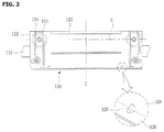
- FIG. 3 is a front view illustrating the hanger plate according to embodiment 1 of the present invention
- FIG. 4 is a plan view of FIG. 3
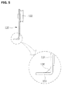
- FIG. 5 is a side view of FIG. 3 .
- a first embossing portion 124 which is backwardly recessed may be formed in the vertical direction.
- the first embossing portion 124 is formed to pass through the line L that is extended in the width direction from the point that corresponds to the center of the roller.
- vertical direction means a length direction of the hanger plate 120, that is, the vertical direction in the hanger plate of FIG. 3
- horizontal direction or “width direction” means a horizontal direction in the with direction of the hanger plate 120, i.e. the horizontal direction in the hanger plate of FIG. 3 .
- a force that is applied to the lower end thereof in the forward or backward direction acts on the hanger plate 120 engaged with the upper end of the door 130.
- the bending of the hanger plate 120 typically occurs in the neighborhood of the connection shaft 123 when such a force is applied thereto. Accordingly, if a force is applied to the elevator door 130 due to a passenger's carelessness or accident, the bending of the hanger plate 120 typically occurs according to the line that connects the center of the roller 122 connected to both sides of the upper part of the hanger plate 120.
- the first embossing portion 124 is formed on the hanger plate 120, the above-described bending can be maximally suppressed. That is, since the first embossing unit 124 is formed to pass the line L extended in the width direction from the point that corresponds to the portion that can be bent most easily, i.e. the center of the roller 122, the rigidity of the hanger plate 120 that can prevent the bending of the hanger plate 120 as described above can be secured. Accordingly, even if a force is applied to the elevator door 130, the separation of the elevator door 130 due to the bending of the hanger plate 120 can be maximally prevented.
- the first embossing portion 124 may be formed by pressing a part of the hanger plate 120 by press or the like, and may be formed to be forwardly projected or to be backwardly recessed according to the manufacturing method. In this embodiment, the first embossing portion 124 that is backwardly recessed is exemplified.
- the bending of the hanger plate 120 typically starts at both ends of the hanger plate 120 in the width direction, the bending of the hanger plate 120 can be prevented more effectively when the first embossing portion 124 is formed in the neighborhood of the both ends of the hanger plate 120 rather than when the first embossing portion 124 is formed in the neighborhood of the center of the width direction. Accordingly, it is preferable that a pair of first embossing portions 124 is formed around the connection shaft 123 of the rollers 122 connected in the neighborhood of the both ends of the hanger plate 120.
- the deformation of the hanger plate 120 causes a problem when the hanger plate 120 is bent in the upward direction as described above.
- the twist of the hanger plate 120 may cause a problem in addition to the bending as described above.
- a second embossing portion 125 may be formed on the hanger plate 120.
- the second embossing portion 125 may be formed by pressing a part of the hanger plate 120 by press or the like, and may be formed to be forwardly projected or to be backwardly recessed according to the manufacturing method.
- the second embossing portion 125 that is backwardly recessed is exemplified.
- the both ends of the hanger plate 120 in the width direction are connected to the connection shaft 123 or the like of the roller 122, and if a force is applied to the hanger plate 120 at the positions that are apart in the width direction from the center line, it is general that the twist occurs in the neighborhood of the center line C that halves a distance between both ends of the hanger plate 120 in the width direction. Accordingly, it is preferable that the second embossing portion 125 is formed to pass through the center line that halves the distance between the both ends of the hanger plate 120 in the width direction.
- the twist of the hanger plate 120 can be prevented more effectively when the second embossing portion 125 is formed in the neighborhood of the both ends of the hanger plate 120 in the upward/downward direction rather than when the second embossing portion 125 is formed in the neighborhood of the center in the upward/downward direction. Accordingly, it is preferable that the second embossing portions 125 are formed in the neighborhood of the both ends of the hanger plate in the upward/downward direction.
- the hanger plate 120 may include a base plate 128 on which the first and second embossing portions 124 and 125 are formed, and a connection plate 129 formed to be vertically bent from one end of the base plate 128. Accordingly, the hanger plate 120 may have an "L"-shaped section as seen from the side.
- connection portion of the base plate 128 and the connection plate 129 is very weak and is easily bent. Accordingly, in order to supplement the weakness as described above, a third embossing portion 126 may be further formed on the hanger plate 120 according to this embodiment of the present invention.
- the third embossing portion 126 which is inwardly projected, may be formed on the connection portion that connects the base plate 128 and the connection plate 129.
- the bending of the connection portion in the upward direction can be prevented by the third embossing unit 126.
- the elevator door device is constructed so as to include the hanger plate having the first to third embossing portions formed thereon, the secession of the elevator door due to the deformation of the hanger plate can be prevented even if a force is applied to the elevator door.
- the elevator door device it is not necessary to change the material of the hanger plate, to increase the thickness thereof, or to engage a separate plate with the hanger plate by a welding process or the like to increase the rigidity, and the rigidity of a part or the whole of the hanger plate can be easily and inexpensively increased to meet the desired level.
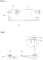
- FIG. 6 is a front view illustrating a hanger plate according to an example useful for illustrating the present invention
- FIG. 7 is a plan view of FIG. 6
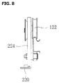
- FIG. 8 is a side view of FIG. 6 .
- the same or proper reference numerals are given to the same or proper constituent elements across the figures, and the detailed description thereof will be omitted.
- An elevator door device includes a hanger case 110, a hanger plate 120, and an elevator door 130.
- the main difference between the elevator door device according to this example and the elevator door device according to the first embodiment is on the point that the construction of the hanger plate according to this example is different from that of the hanger plate according to the first embodiment, and the elevator door device according to this example will be described centering around the hanger plate with reference to FIGS. 6 to 8 .
- the hanger plate 220 is provided with bent portions 224 which are provided at both ends of the hanger plate 220 in the width direction.
- the bent portions 224 are formed to be bent from the hanger plate 220 in the forward or backward direction. Also, the bent portions 224 are formed to pass through the line L extended in the width direction from the point that corresponds to the center of the roller 122.
- the bent portion 224 is formed to pass the line L extended in the width direction from the point that corresponds to the portion that can be bent most easily, i.e. the center of the roller 122.
- the bent portion 224 is formed from the upper end to the lower end of the hanger plate 220.
- the deformation is prevented more effectively in the case where the thickness or the length of the bent portion 224 is increased, it is preferable that the thickness or the length is properly selected in consideration of the space or cost thereof.
Landscapes
- Elevator Door Apparatuses (AREA)
Claims (6)
- Aufhängungsplatte (120) für einen Aufzug, wobei die Aufhängungsplatte (120) zum Verbinden eines Aufhängungsgehäuses (110), das an einem oberen Teil einer Aufzugtüröffnung (150) installiert ist und eine in einer Breitenrichtung der Aufzugtüröffnung (150) ausgebildete Aufhängungsschiene (112) aufweist, mit einer Aufzugtür (130) geeignet ist, welche durch die Aufhängungsschiene (112) geführt ist, um sich in die Breitenrichtung der Aufzugtüröffnung (150) zu bewegen, durch eine sich an der Aufhängungsschiene (112) drehende Rolle (122), dadurch gekennzeichnet, dass die Aufhängungsplatte (120) umfasst:einen ersten Ausbauchungsabschnitt (124), welcher nach vorne vorsteht oder nach hinten ausgespart ist, und in einer vertikalen Richtung ausgebildet ist, um durch eine Linie durchzugehen, die von einem Punkt, welcher der Mitte der Rolle (122) entspricht, in der Breitenrichtung verlängert ist.
- Aufhängungsplatte (120) nach Anspruch 1, ferner mit einem zweiten Ausbauchungsabschnitt (125), welcher nach vorne vorsteht oder nach hinten ausgespart ist, und in einer horizontalen Richtung ausgebildet ist, und wobei der zweite Ausbauchungsabschnitt (125) ausgebildet ist, um durch eine Mittellinie durchzugehen, die einen Abstand zwischen beiden Enden der Aufhängungsplatte (120) in der Breitenrichtung halbiert.
- Aufhängungsplatte (120) nach Anspruch 1 oder 2, ferner mit einer Basisplatte (128) und einer Verbindungsplatte (129), die ausgebildet ist, um von einem Ende der Basisplatte (128) vertikal gebogen zu sein;
wobei ein dritter Ausbauchungsabschnitt (126), welcher nach innen vorsteht, an einem Verbindungsabschnitt ausgebildet ist, der die Basisplatte (128) und die Verbindungsplatte (129) verbindet, um das Biegen der Verbindungsplatte (129) zu der Basisplatte (128) hin zu verhindern. - Aufhängungsplatte (120) nach Anspruch 1 oder 2, ferner mit Biegeabschnitten, welche ausgebildet sind, um von der Aufhängungsplatte (120) in eine Vorwärts- oder Rückwärtsrichtung gebogen zu sein, und in einer vertikalen Richtung verlängert sind, um durch eine in die Breitenrichtung verlängerte Linie durchzugehen, von einem Punkt, welcher der Mitte der Rolle (122) entspricht.
- Aufzugtürvorrichtung, mit:einem Aufhängungsgehäuse (110), das an einem oberen Teil einer Aufzugtüröffnung (150) installiert ist und eine in einer Breitenrichtung der Aufzugtüröffnung (150) ausgebildete Aufhängungsschiene (112) aufweist;einer Aufhängungsplatte (120) nach einem der vorhergehenden Ansprüche, wobei die Aufhängungsplatte (120) mit einer sich an der Aufhängungsschiene (112) drehenden Rolle (122) verbunden ist, um sich als Reaktion auf die Drehung der Rolle (122) an der Aufhängungsschiene (112) in die Breitenrichtung der Aufzugtüröffnung (150) zu bewegen; undeiner Aufzugtür (130), die mit der Aufhängungsplatte (120) im Eingriff ist, um die Aufzugtüröffnung (150) gemäß der Links-/Rechts-Bewegung der Aufhängungsplatte (120) zu öffnen/schließen.
- Aufzugtürvorrichtung nach Anspruch 5, wobei ein Paar erster Ausbauchungsabschnitte (124) um eine Verbindungswelle (123) herum ausgebildet ist, welche die Aufhängungsplatte (120) und die Rolle (122) verbindet.
Applications Claiming Priority (2)
| Application Number | Priority Date | Filing Date | Title |
|---|---|---|---|
| KR1020080039364A KR100956917B1 (ko) | 2008-04-28 | 2008-04-28 | 엘리베이터용 행거 플레이트 및 이를 포함하는 엘리베이터도어 장치 |
| PCT/KR2009/002201 WO2009134045A2 (ko) | 2008-04-28 | 2009-04-28 | 엘리베이터용 행거 플레이트 및 이를 포함하는 엘리베이터 도어 장치 |
Publications (3)
| Publication Number | Publication Date |
|---|---|
| EP2269934A2 EP2269934A2 (de) | 2011-01-05 |
| EP2269934A4 EP2269934A4 (de) | 2015-01-07 |
| EP2269934B1 true EP2269934B1 (de) | 2016-08-24 |
Family
ID=41255540
Family Applications (1)
| Application Number | Title | Priority Date | Filing Date |
|---|---|---|---|
| EP09738951.4A Not-in-force EP2269934B1 (de) | 2008-04-28 | 2009-04-28 | Aufhängungsplatte für einen aufzug und aufzugtürvorrichtung damit |
Country Status (5)
| Country | Link |
|---|---|
| EP (1) | EP2269934B1 (de) |
| JP (1) | JP5241913B2 (de) |
| KR (1) | KR100956917B1 (de) |
| CN (1) | CN102015509B (de) |
| WO (1) | WO2009134045A2 (de) |
Families Citing this family (2)
| Publication number | Priority date | Publication date | Assignee | Title |
|---|---|---|---|---|
| KR101722331B1 (ko) * | 2015-10-16 | 2017-03-31 | 이미숙 | 엘리베이터 도어 이탈 방지 구조 |
| JP7710618B2 (ja) * | 2022-09-16 | 2025-07-18 | 三菱電機ビルソリューションズ株式会社 | エレベータードア装置システム |
Family Cites Families (10)
| Publication number | Priority date | Publication date | Assignee | Title |
|---|---|---|---|---|
| JPS5968775U (ja) * | 1982-10-29 | 1984-05-10 | 株式会社東芝 | エレベ−タ |
| JPS59198278A (ja) * | 1983-04-25 | 1984-11-10 | 三菱電機株式会社 | 主枠装置 |
| JPH03589Y2 (de) * | 1986-11-10 | 1991-01-10 | ||
| JPH0764506B2 (ja) * | 1988-05-31 | 1995-07-12 | 三菱電機株式会社 | エレベーターのドア装置 |
| JPH0764508B2 (ja) * | 1989-07-07 | 1995-07-12 | 三菱電機株式会社 | エレベーター用ドアの据付装置 |
| JPH02292520A (ja) * | 1990-04-20 | 1990-12-04 | Fuji Kiko Co Ltd | 自在継手 |
| JPH072536Y2 (ja) * | 1991-05-01 | 1995-01-25 | 株式会社クマリフト技術研究所 | 三枚横引きドアに於ける高速ドアレールの振止め装置 |
| US5881844A (en) | 1996-11-07 | 1999-03-16 | Otis Elevator Company | Secondary positioning system for elevator car doors |
| JP2001227233A (ja) | 2000-02-18 | 2001-08-24 | Showa Denko Kk | 冷蔵庫等におけるスライド扉の脱輪防止装置 |
| KR100462277B1 (ko) * | 2002-07-03 | 2004-12-17 | 주식회사 미륭산업 | 엘레베이터 도어용 행거 케이스 제조방법 |
-
2008
- 2008-04-28 KR KR1020080039364A patent/KR100956917B1/ko active Active
-
2009
- 2009-04-28 EP EP09738951.4A patent/EP2269934B1/de not_active Not-in-force
- 2009-04-28 CN CN2009801148287A patent/CN102015509B/zh not_active Expired - Fee Related
- 2009-04-28 JP JP2011504937A patent/JP5241913B2/ja not_active Expired - Fee Related
- 2009-04-28 WO PCT/KR2009/002201 patent/WO2009134045A2/ko not_active Ceased
Also Published As
| Publication number | Publication date |
|---|---|
| KR20090113568A (ko) | 2009-11-02 |
| KR100956917B1 (ko) | 2010-05-11 |
| WO2009134045A2 (ko) | 2009-11-05 |
| CN102015509A (zh) | 2011-04-13 |
| WO2009134045A3 (ko) | 2010-01-21 |
| EP2269934A4 (de) | 2015-01-07 |
| EP2269934A2 (de) | 2011-01-05 |
| CN102015509B (zh) | 2013-05-29 |
| JP2011517649A (ja) | 2011-06-16 |
| JP5241913B2 (ja) | 2013-07-17 |
Similar Documents
| Publication | Publication Date | Title |
|---|---|---|
| US11052788B2 (en) | Longitudinal adjuster and vehicle seat | |
| EP2335991A2 (de) | Sicherheitsfusshalterung für eine u-bahn-plattform | |
| US9365095B2 (en) | Vehicle door | |
| JPH1159238A (ja) | シートスライド装置 | |
| EP2269936B1 (de) | Struktur zur vermeidung der trennung einer aufzugsschachttür | |
| EP2688826A1 (de) | Schürzenanordnung für ein aufzugssystem | |
| US10647184B2 (en) | Sunroof apparatus | |
| EP2269934B1 (de) | Aufhängungsplatte für einen aufzug und aufzugtürvorrichtung damit | |
| US20150203000A1 (en) | Vehicle seat | |
| EP2298685A2 (de) | Türenmechanismus für aufzüge | |
| JP4823658B2 (ja) | 車両のスライドドア構造 | |
| JP2012025255A (ja) | 車両用ドア | |
| EP2189315B1 (de) | Sonnenblendenvorrichtung für Fahrzeug | |
| US8661738B2 (en) | Door frame assembly and method | |
| CN204383140U (zh) | 车辆用滑门 | |
| US20150246598A1 (en) | Vehicle door | |
| JP3603521B2 (ja) | 車両のドアパネル | |
| US12330484B2 (en) | Vehicle door system and a method for improving durability of a door system | |
| JP2013121795A (ja) | 戸挟み検知システム | |
| US20130299665A1 (en) | Seat rail for a motor vehicle seat | |
| JP5344428B2 (ja) | エレベータドア装置 | |
| EP4197837B1 (de) | Dachsystem und verfahren zum betrieb davon | |
| JP7754068B2 (ja) | 車両側部構造 | |
| JP2023123175A (ja) | 車両構造 | |
| JP7129882B2 (ja) | ホームドア装置 |
Legal Events
| Date | Code | Title | Description |
|---|---|---|---|
| PUAI | Public reference made under article 153(3) epc to a published international application that has entered the european phase |
Free format text: ORIGINAL CODE: 0009012 |
|
| 17P | Request for examination filed |
Effective date: 20101013 |
|
| AK | Designated contracting states |
Kind code of ref document: A2 Designated state(s): AT BE BG CH CY CZ DE DK EE ES FI FR GB GR HR HU IE IS IT LI LT LU LV MC MK MT NL NO PL PT RO SE SI SK TR |
|
| AX | Request for extension of the european patent |
Extension state: AL BA RS |
|
| DAX | Request for extension of the european patent (deleted) | ||
| A4 | Supplementary search report drawn up and despatched |
Effective date: 20141204 |
|
| RIC1 | Information provided on ipc code assigned before grant |
Ipc: B66B 13/08 20060101ALI20141128BHEP Ipc: B66B 13/02 20060101AFI20141128BHEP |
|
| GRAP | Despatch of communication of intention to grant a patent |
Free format text: ORIGINAL CODE: EPIDOSNIGR1 |
|
| INTG | Intention to grant announced |
Effective date: 20160315 |
|
| GRAS | Grant fee paid |
Free format text: ORIGINAL CODE: EPIDOSNIGR3 |
|
| GRAA | (expected) grant |
Free format text: ORIGINAL CODE: 0009210 |
|
| AK | Designated contracting states |
Kind code of ref document: B1 Designated state(s): AT BE BG CH CY CZ DE DK EE ES FI FR GB GR HR HU IE IS IT LI LT LU LV MC MK MT NL NO PL PT RO SE SI SK TR |
|
| REG | Reference to a national code |
Ref country code: GB Ref legal event code: FG4D |
|
| REG | Reference to a national code |
Ref country code: CH Ref legal event code: EP |
|
| REG | Reference to a national code |
Ref country code: AT Ref legal event code: REF Ref document number: 822875 Country of ref document: AT Kind code of ref document: T Effective date: 20160915 |
|
| REG | Reference to a national code |
Ref country code: IE Ref legal event code: FG4D |
|
| REG | Reference to a national code |
Ref country code: DE Ref legal event code: R096 Ref document number: 602009040607 Country of ref document: DE |
|
| REG | Reference to a national code |
Ref country code: LT Ref legal event code: MG4D |
|
| REG | Reference to a national code |
Ref country code: NL Ref legal event code: MP Effective date: 20160824 |
|
| REG | Reference to a national code |
Ref country code: AT Ref legal event code: MK05 Ref document number: 822875 Country of ref document: AT Kind code of ref document: T Effective date: 20160824 |
|
| PG25 | Lapsed in a contracting state [announced via postgrant information from national office to epo] |
Ref country code: NO Free format text: LAPSE BECAUSE OF FAILURE TO SUBMIT A TRANSLATION OF THE DESCRIPTION OR TO PAY THE FEE WITHIN THE PRESCRIBED TIME-LIMIT Effective date: 20161124 Ref country code: IT Free format text: LAPSE BECAUSE OF FAILURE TO SUBMIT A TRANSLATION OF THE DESCRIPTION OR TO PAY THE FEE WITHIN THE PRESCRIBED TIME-LIMIT Effective date: 20160824 Ref country code: NL Free format text: LAPSE BECAUSE OF FAILURE TO SUBMIT A TRANSLATION OF THE DESCRIPTION OR TO PAY THE FEE WITHIN THE PRESCRIBED TIME-LIMIT Effective date: 20160824 Ref country code: LT Free format text: LAPSE BECAUSE OF FAILURE TO SUBMIT A TRANSLATION OF THE DESCRIPTION OR TO PAY THE FEE WITHIN THE PRESCRIBED TIME-LIMIT Effective date: 20160824 Ref country code: FI Free format text: LAPSE BECAUSE OF FAILURE TO SUBMIT A TRANSLATION OF THE DESCRIPTION OR TO PAY THE FEE WITHIN THE PRESCRIBED TIME-LIMIT Effective date: 20160824 Ref country code: HR Free format text: LAPSE BECAUSE OF FAILURE TO SUBMIT A TRANSLATION OF THE DESCRIPTION OR TO PAY THE FEE WITHIN THE PRESCRIBED TIME-LIMIT Effective date: 20160824 |
|
| PG25 | Lapsed in a contracting state [announced via postgrant information from national office to epo] |
Ref country code: GR Free format text: LAPSE BECAUSE OF FAILURE TO SUBMIT A TRANSLATION OF THE DESCRIPTION OR TO PAY THE FEE WITHIN THE PRESCRIBED TIME-LIMIT Effective date: 20161125 Ref country code: ES Free format text: LAPSE BECAUSE OF FAILURE TO SUBMIT A TRANSLATION OF THE DESCRIPTION OR TO PAY THE FEE WITHIN THE PRESCRIBED TIME-LIMIT Effective date: 20160824 Ref country code: LV Free format text: LAPSE BECAUSE OF FAILURE TO SUBMIT A TRANSLATION OF THE DESCRIPTION OR TO PAY THE FEE WITHIN THE PRESCRIBED TIME-LIMIT Effective date: 20160824 Ref country code: AT Free format text: LAPSE BECAUSE OF FAILURE TO SUBMIT A TRANSLATION OF THE DESCRIPTION OR TO PAY THE FEE WITHIN THE PRESCRIBED TIME-LIMIT Effective date: 20160824 Ref country code: PT Free format text: LAPSE BECAUSE OF FAILURE TO SUBMIT A TRANSLATION OF THE DESCRIPTION OR TO PAY THE FEE WITHIN THE PRESCRIBED TIME-LIMIT Effective date: 20161226 Ref country code: SE Free format text: LAPSE BECAUSE OF FAILURE TO SUBMIT A TRANSLATION OF THE DESCRIPTION OR TO PAY THE FEE WITHIN THE PRESCRIBED TIME-LIMIT Effective date: 20160824 |
|
| PG25 | Lapsed in a contracting state [announced via postgrant information from national office to epo] |
Ref country code: RO Free format text: LAPSE BECAUSE OF FAILURE TO SUBMIT A TRANSLATION OF THE DESCRIPTION OR TO PAY THE FEE WITHIN THE PRESCRIBED TIME-LIMIT Effective date: 20160824 Ref country code: EE Free format text: LAPSE BECAUSE OF FAILURE TO SUBMIT A TRANSLATION OF THE DESCRIPTION OR TO PAY THE FEE WITHIN THE PRESCRIBED TIME-LIMIT Effective date: 20160824 |
|
| REG | Reference to a national code |
Ref country code: DE Ref legal event code: R097 Ref document number: 602009040607 Country of ref document: DE |
|
| PG25 | Lapsed in a contracting state [announced via postgrant information from national office to epo] |
Ref country code: CZ Free format text: LAPSE BECAUSE OF FAILURE TO SUBMIT A TRANSLATION OF THE DESCRIPTION OR TO PAY THE FEE WITHIN THE PRESCRIBED TIME-LIMIT Effective date: 20160824 Ref country code: PL Free format text: LAPSE BECAUSE OF FAILURE TO SUBMIT A TRANSLATION OF THE DESCRIPTION OR TO PAY THE FEE WITHIN THE PRESCRIBED TIME-LIMIT Effective date: 20160824 Ref country code: SK Free format text: LAPSE BECAUSE OF FAILURE TO SUBMIT A TRANSLATION OF THE DESCRIPTION OR TO PAY THE FEE WITHIN THE PRESCRIBED TIME-LIMIT Effective date: 20160824 Ref country code: BE Free format text: LAPSE BECAUSE OF FAILURE TO SUBMIT A TRANSLATION OF THE DESCRIPTION OR TO PAY THE FEE WITHIN THE PRESCRIBED TIME-LIMIT Effective date: 20160824 Ref country code: DK Free format text: LAPSE BECAUSE OF FAILURE TO SUBMIT A TRANSLATION OF THE DESCRIPTION OR TO PAY THE FEE WITHIN THE PRESCRIBED TIME-LIMIT Effective date: 20160824 Ref country code: BG Free format text: LAPSE BECAUSE OF FAILURE TO SUBMIT A TRANSLATION OF THE DESCRIPTION OR TO PAY THE FEE WITHIN THE PRESCRIBED TIME-LIMIT Effective date: 20161124 |
|
| PLBE | No opposition filed within time limit |
Free format text: ORIGINAL CODE: 0009261 |
|
| STAA | Information on the status of an ep patent application or granted ep patent |
Free format text: STATUS: NO OPPOSITION FILED WITHIN TIME LIMIT |
|
| 26N | No opposition filed |
Effective date: 20170526 |
|
| PG25 | Lapsed in a contracting state [announced via postgrant information from national office to epo] |
Ref country code: SI Free format text: LAPSE BECAUSE OF FAILURE TO SUBMIT A TRANSLATION OF THE DESCRIPTION OR TO PAY THE FEE WITHIN THE PRESCRIBED TIME-LIMIT Effective date: 20160824 |
|
| REG | Reference to a national code |
Ref country code: CH Ref legal event code: PL |
|
| GBPC | Gb: european patent ceased through non-payment of renewal fee |
Effective date: 20170428 |
|
| REG | Reference to a national code |
Ref country code: IE Ref legal event code: MM4A |
|
| REG | Reference to a national code |
Ref country code: FR Ref legal event code: ST Effective date: 20171229 |
|
| PG25 | Lapsed in a contracting state [announced via postgrant information from national office to epo] |
Ref country code: MC Free format text: LAPSE BECAUSE OF FAILURE TO SUBMIT A TRANSLATION OF THE DESCRIPTION OR TO PAY THE FEE WITHIN THE PRESCRIBED TIME-LIMIT Effective date: 20160824 Ref country code: FR Free format text: LAPSE BECAUSE OF NON-PAYMENT OF DUE FEES Effective date: 20170502 |
|
| PG25 | Lapsed in a contracting state [announced via postgrant information from national office to epo] |
Ref country code: LI Free format text: LAPSE BECAUSE OF NON-PAYMENT OF DUE FEES Effective date: 20170430 Ref country code: CH Free format text: LAPSE BECAUSE OF NON-PAYMENT OF DUE FEES Effective date: 20170430 Ref country code: LU Free format text: LAPSE BECAUSE OF NON-PAYMENT OF DUE FEES Effective date: 20170428 Ref country code: GB Free format text: LAPSE BECAUSE OF NON-PAYMENT OF DUE FEES Effective date: 20170428 |
|
| PG25 | Lapsed in a contracting state [announced via postgrant information from national office to epo] |
Ref country code: IE Free format text: LAPSE BECAUSE OF NON-PAYMENT OF DUE FEES Effective date: 20170428 |
|
| PG25 | Lapsed in a contracting state [announced via postgrant information from national office to epo] |
Ref country code: MT Free format text: LAPSE BECAUSE OF NON-PAYMENT OF DUE FEES Effective date: 20170428 |
|
| PG25 | Lapsed in a contracting state [announced via postgrant information from national office to epo] |
Ref country code: HU Free format text: LAPSE BECAUSE OF FAILURE TO SUBMIT A TRANSLATION OF THE DESCRIPTION OR TO PAY THE FEE WITHIN THE PRESCRIBED TIME-LIMIT; INVALID AB INITIO Effective date: 20090428 |
|
| PG25 | Lapsed in a contracting state [announced via postgrant information from national office to epo] |
Ref country code: CY Free format text: LAPSE BECAUSE OF NON-PAYMENT OF DUE FEES Effective date: 20160824 |
|
| PG25 | Lapsed in a contracting state [announced via postgrant information from national office to epo] |
Ref country code: MK Free format text: LAPSE BECAUSE OF FAILURE TO SUBMIT A TRANSLATION OF THE DESCRIPTION OR TO PAY THE FEE WITHIN THE PRESCRIBED TIME-LIMIT Effective date: 20160824 |
|
| PG25 | Lapsed in a contracting state [announced via postgrant information from national office to epo] |
Ref country code: TR Free format text: LAPSE BECAUSE OF FAILURE TO SUBMIT A TRANSLATION OF THE DESCRIPTION OR TO PAY THE FEE WITHIN THE PRESCRIBED TIME-LIMIT Effective date: 20160824 |
|
| PG25 | Lapsed in a contracting state [announced via postgrant information from national office to epo] |
Ref country code: IS Free format text: LAPSE BECAUSE OF FAILURE TO SUBMIT A TRANSLATION OF THE DESCRIPTION OR TO PAY THE FEE WITHIN THE PRESCRIBED TIME-LIMIT Effective date: 20161224 |
|
| PGFP | Annual fee paid to national office [announced via postgrant information from national office to epo] |
Ref country code: DE Payment date: 20220425 Year of fee payment: 14 |
|
| REG | Reference to a national code |
Ref country code: DE Ref legal event code: R119 Ref document number: 602009040607 Country of ref document: DE |
|
| PG25 | Lapsed in a contracting state [announced via postgrant information from national office to epo] |
Ref country code: DE Free format text: LAPSE BECAUSE OF NON-PAYMENT OF DUE FEES Effective date: 20231103 |