EP2268562B1 - Shuttle-bahnhof und shuttle-kanallager - Google Patents
Shuttle-bahnhof und shuttle-kanallager Download PDFInfo
- Publication number
- EP2268562B1 EP2268562B1 EP08874093.1A EP08874093A EP2268562B1 EP 2268562 B1 EP2268562 B1 EP 2268562B1 EP 08874093 A EP08874093 A EP 08874093A EP 2268562 B1 EP2268562 B1 EP 2268562B1
- Authority
- EP
- European Patent Office
- Prior art keywords
- channel
- station
- shuttle
- shelf
- frame
- Prior art date
- Legal status (The legal status is an assumption and is not a legal conclusion. Google has not performed a legal analysis and makes no representation as to the accuracy of the status listed.)
- Not-in-force
Links
- 238000012546 transfer Methods 0.000 claims description 43
- 239000000969 carrier Substances 0.000 claims description 10
- 238000000151 deposition Methods 0.000 claims description 3
- 238000004146 energy storage Methods 0.000 claims description 3
- 230000004888 barrier function Effects 0.000 description 7
- 239000002800 charge carrier Substances 0.000 description 6
- OKTJSMMVPCPJKN-UHFFFAOYSA-N Carbon Chemical compound [C] OKTJSMMVPCPJKN-UHFFFAOYSA-N 0.000 description 5
- 238000000034 method Methods 0.000 description 5
- XEEYBQQBJWHFJM-UHFFFAOYSA-N Iron Chemical compound [Fe] XEEYBQQBJWHFJM-UHFFFAOYSA-N 0.000 description 4
- 230000006378 damage Effects 0.000 description 4
- 238000012544 monitoring process Methods 0.000 description 4
- 208000027418 Wounds and injury Diseases 0.000 description 3
- 208000014674 injury Diseases 0.000 description 3
- 238000003780 insertion Methods 0.000 description 3
- 230000037431 insertion Effects 0.000 description 3
- 230000008878 coupling Effects 0.000 description 2
- 238000010168 coupling process Methods 0.000 description 2
- 238000005859 coupling reaction Methods 0.000 description 2
- 229910052742 iron Inorganic materials 0.000 description 2
- 238000012986 modification Methods 0.000 description 2
- 230000004048 modification Effects 0.000 description 2
- 230000007704 transition Effects 0.000 description 2
- 238000006243 chemical reaction Methods 0.000 description 1
- 238000004891 communication Methods 0.000 description 1
- 230000007423 decrease Effects 0.000 description 1
- 230000003247 decreasing effect Effects 0.000 description 1
- 238000013461 design Methods 0.000 description 1
- 239000012634 fragment Substances 0.000 description 1
- 238000002955 isolation Methods 0.000 description 1
- 239000000463 material Substances 0.000 description 1
- 230000007246 mechanism Effects 0.000 description 1
- 230000003287 optical effect Effects 0.000 description 1
- 238000012946 outsourcing Methods 0.000 description 1
- 230000002093 peripheral effect Effects 0.000 description 1
- 230000008569 process Effects 0.000 description 1
- 230000001105 regulatory effect Effects 0.000 description 1
- 230000000007 visual effect Effects 0.000 description 1
Images




Classifications
-
- B—PERFORMING OPERATIONS; TRANSPORTING
- B65—CONVEYING; PACKING; STORING; HANDLING THIN OR FILAMENTARY MATERIAL
- B65G—TRANSPORT OR STORAGE DEVICES, e.g. CONVEYORS FOR LOADING OR TIPPING, SHOP CONVEYOR SYSTEMS OR PNEUMATIC TUBE CONVEYORS
- B65G1/00—Storing articles, individually or in orderly arrangement, in warehouses or magazines
- B65G1/02—Storage devices
- B65G1/04—Storage devices mechanical
- B65G1/0492—Storage devices mechanical with cars adapted to travel in storage aisles
-
- B—PERFORMING OPERATIONS; TRANSPORTING
- B65—CONVEYING; PACKING; STORING; HANDLING THIN OR FILAMENTARY MATERIAL
- B65G—TRANSPORT OR STORAGE DEVICES, e.g. CONVEYORS FOR LOADING OR TIPPING, SHOP CONVEYOR SYSTEMS OR PNEUMATIC TUBE CONVEYORS
- B65G1/00—Storing articles, individually or in orderly arrangement, in warehouses or magazines
- B65G1/02—Storage devices
- B65G1/04—Storage devices mechanical
- B65G1/0407—Storage devices mechanical using stacker cranes
- B65G1/0414—Storage devices mechanical using stacker cranes provided with satellite cars adapted to travel in storage racks
Definitions
- the present invention relates to a shuttle station according to claim 1, which allows shelf-bound sewer vehicles, so-called shuttle, safely implement between different channels of the channel storage.
- a conventional channel warehouse is in the DE 38 40 648 A1 shown.
- a control panel for a channel warehouse is in the US 3,800,963 shown.
- Shuttle channel storage systematically belong to the so-called compact storage or channel storage.
- Load carriers such as pallets or trays, are on rails standing in a row stored in channels.
- a rack channel are usually two or more storage units consisting of charge carriers (s) and articles in a row.
- a correspondingly flat positioning unit (shuttle) can drive under the load carriers and, after lifting, transport them in the longitudinal direction of the channel in order to carry out storage and retrieval.
- the shuttle usually arrives on a rack conveyor (stacker crane, stacker, etc.) with a correspondingly adapted recording device in a channel.
- C-shaped rails were proposed, which were open in the direction of the channel center and allowed small clearances relative to each other. At the front end of the channel, these C-shaped rails had recesses in the upper part of the C-profile, which had approximately the width of the rollers.
- the European patent EP 1 554 198 alternatively proposes a shelf rail, which has a horizontally oriented storage surface and a horizontally oriented tread, which are interconnected via an inclined side wall. Two opposing such rails taper from top to bottom, thus forming a funnel-shaped traversing plane.
- the funnel-shaped design facilitates the lifting of the shuttle from above into the channel considerably.
- shuttle vehicles which are permanently connected for the purpose of control and power supply via a cable with a stacker crane.
- operators working in the warehouse must be protected against injuries from automated shuttles.
- it is desirable that the shuttles can be easily, safely and reliably implemented between different channels.
- a shuttle station in a channel storage system which has at least one rack with a plurality of channels running in a longitudinal direction, the station having a frame which can be inserted into an end of a channel by a stacker crane or a regulating conveyor in that rail sections of the rack are coupled substantially flush with rack rails of the channel so that the shuttle can enter and exit the channel to lift, transfer and / or unload carriers, the rack being further dimensioned to allow the shuttle to travel during a Conversion of the frame may remain from the end of a channel to one end of another channel in the frame.
- a shuttle including a shuttle station is implemented according to the present invention.
- the shuttle is located in the station.
- the shuttle is thus protected.
- the station is designed so that rails provided in the station preferably couple seamlessly to the rails in the rack channel when the station is inserted into a transfer station in the channel. Implementing the station can be done with less care than repositioning a shuttle alone. If an operator, e.g. when inserting the station on the shelf, on the shelf, the shuttle remains undamaged. The shuttle does not touch the shelf. Only the station touches the shelf.
- the station is inserted into the channel, this is visually recognizable to an operator. As soon as a station is inserted into a channel, the operator knows that a shuttle is operating in this channel.
- the rail portions extend in the longitudinal direction and have between them a clearance, which corresponds substantially to a clearance between the shelf rails of the channel.
- the distance between the rail sections should correspond to this distance, so as to allow a low-resistance transition of the shuttle between the station and the channel.
- the shuttle may have side spacing rollers that hold the shuttle in the space between the rails. With identical rail spacing, the shuttle can not tilt during the transition.
- the rail sections and the shelf rails appear to be integrally formed. The guide rollers rotate in a horizontal plane, whereas the actual rollers of the shuttle rotate in a vertical plane.
- the frame according to the invention further comprises a Querzentrier founded having horizontally oriented shelves and extending from a channel top to a channel bottom out in such a way funnel-shaped tapered, that a to be positioned on the shelves carrier is centered when lowering to the station in the transverse direction of the channel.
- a charge carrier to be incorporated into the channel is e.g. lifted by a stacker in the channel.
- the load carrier is lowered by means of a lifting device of the truck in the direction of the station.
- the charge carrier With the aid of the centering device, the charge carrier is centered during the lowering in the transverse direction of the channel, that is to say relative to the center of the channel, since the clear distance of the elements of the centering aid decreases with decreasing height.
- the shuttle can then transfer the carrier thus centered to its storage location in the channel and no longer has to worry about the orientation of the charge carrier in the channel transverse direction.
- sensor devices and manipulation devices to determine the position of the charge carriers in the transverse direction and influence.
- the frame according to the invention has an end stop.
- the end stop prevents a carrier positioned on the rack from being pulled out of the channel.
- the end stop is thus arranged in a plane which lies above the driving plane of the shuttle.
- the end stop also serves to prevent inadvertent removal of a load carrier by a load-handling means of a stacker crane. This is particularly advantageous when depositing a load carrier on the station. But even with a mispositioning of a carrier in the station, which is picked up by the shuttle from a storage place in the channel, it is prevented that the shuttle the carrier via the station, i. over a shelf front, carried out.
- the frame is closed at a side remote from the channel end by means of a stop device, which preferably protrudes with respect to a channel width, preferably on both sides.
- the stop device may be a sheet that connects the frame or the settler at one end in the transverse direction.
- the frame then has a U-shaped cross-section in a plan view.
- the stop device prevents the shuttle from driving out of the canal into the station beyond the station. This will prevent the shuttle from falling off the shelf at the entrance to the canal.
- the stop device serves as a mechanical stop, e.g. for a mast of a forklift when storing a load carrier. Especially at high altitudes, maneuvering is difficult for stackers. When storing load carriers, it may happen that the stack driver drives with the lift mast of the truck against the stop device of the station. Damage to the station's shuttle through the truck is excluded.
- the stop device further prevents or impedes the access of personnel to the affected channel.
- the stop device is thus already an optical sign for operators, that in a channel with a, preferably automated, shuttle is working.
- the stop device further supports a transfer of the station itself.
- the stop device when inserting the station into a channel, serves as a mechanical stop when inserting the station into a transfer point of the shelf.
- the stations are implemented with the same shelf truck as the load carriers themselves.
- the station preferably has a settling device or load-receiving coupling device on its underside.
- the settling device can be adapted to cooperate in a transfer of the station between channels with a load-receiving means of a shelf truck such that the station can be raised from a first channel and / or pulled out and lowered into a second channel and / or pushed.
- the settling device and the load receiving means are matched to one another so that the station can be handled like a load carrier. Thus, no separate storage and retrieval unit is required to implement the station, resulting in a corresponding investment savings.
- the station has a terminal for electrical connection to an electrified racking channel or an exchangeable energy store to power the shuttle when in the station, in particular with a charge current for accumulators or supercapacitors provided on the shuttle , to supply.
- the station then has another connection to make an electrical connection between the shuttle and the station.
- a permanent connection, e.g. with a cable, between the shuttle and the station or the rack conveyor is not required.
- the station has a longitudinally acting sensor device.
- the sensor device allows monitoring of the space between the shuttle and the station.
- a sensor device for example, a light or laser barrier can be used, which generates a light or laser beam in the longitudinal direction of the channel. If the beam is interrupted, for example, by an operator entering the channel (laterally), this can be detected both on the side of the shuttle and on the side of the station and lead to an emergency stop. This measure additionally increases security.
- a shelf for a channel store having a plurality of channels for positioning a plurality of load carriers therein on rack rails disposed laterally on shelf stands, each channel having a shelf transfer slot configured such that it can accommodate a shuttle station so that the rack rails of a subsequent to the transfer point channel storage place essentially flush with rail sections of the frame, so that a shuttle from the station can enter the channel and drive back to the station.
- the shelf or the channels are thus adapted to receive the station described above.
- the station can be lifted and / or inserted into the transfer stations. The transfer of the station between different channels is easily possible.
- a channel storage which comprises a shuttle station of the type described above and a shelf of the type described above.
- a method of providing a shuttle in various channels of a warehouse comprising the steps of: shuttleing to a shuttle station; Decoupling the station equipped with the shuttle from a transfer point of a first channel of a shelf, preferably by lifting and / or pulling out of the station by means of a stacker crane or by means of a stacker; and converting the station equipped with the shuttle by means of the stacker crane or by means of the stacker in a transfer area of another channel.
- Fig. 1 shows a schematic perspective view of a shuttle channel bearing 10 according to the present invention.
- the channel storage 10 has a block of shelves 12 arranged side by side.
- a shelf front spans out into an XY plane.
- a shelf depth runs in a Z direction.
- Each of the shelves 12 has here, by way of example, four shelf channels 14 arranged one above the other. More or less channels and shelves can be provided.
- the channels 14 are used for storage of load carriers 16, such as pallets, trays, etc., which in turn are equipped with articles 18. In the following example pallets are used as charge carriers.
- the equipped with articles 18 pallets 16 are stored by means of a rack conveyor 20 in the channels 14 and outsourced.
- Fig. 1 By way of example, a stacker 20 is shown.
- the supply of the shelves 12 can be done, for example, with a stacker crane.
- the storage and retrieval unit is preferably rail-guided and supplies shelf fronts of opposite shelves, wherein in Fig. 1 only one block is shown with pallets 16.
- the space between two rack blocks in which the stacker crane (s) move is referred to as a rack aisle that typically extends in the X direction.
- a shuttle 22 is a rail-guided vehicle with a vertically (Y) movable lifting device.
- the rails of the shuttle 22, which in the Fig. 1 are not explicitly shown, are attached to the shelf 12 so that the shuttle 22 with lowered lifting a pallet 16 can go under, the pallet 16 can lift with the lifting device and the pallet 16 then for storage in the channel 14 into or for outsourcing to the Can transport shelf front.
- the shuttle 22 is provided with suitable sensors to determine a distance to already stored pallets 16 or to a channel end.
- the shuttle 22 is usually inserted by means of the stacker 20 in a predetermined channel 14 of the shelf 12.
- the pallet 16 When storing a pallet 16 in this predetermined channel 14, the pallet 16 is moved to a transfer station, with reference to Fig. 3 will be described in more detail. From there, the shuttle 22 picks up the pallet 16 and stores it. A removal process takes place in reverse order. If a channel 14 is full or empty, the shuttle 22 can be implemented. Of course, the shuttle 22 can be implemented at any time. Depending on the requirement, a channel 14 can be completely filled or emptied with pallets 16. For this purpose, individual pallets 16 are stored or outsourced. In an application as a continuous storage is stored from a shelf front. From an opposite shelf front, ie at a back, is outsourced. When emptying empty storage bins are refilled with already stored pallets 16 by forward movement of the same by means of the shuttle 22, so that Einlagerrax bins are free again.
- Fig. 2 a and 2b show a first embodiment of a shuttle station 30 according to the present invention in a perspective view.
- Fig. 2a shows a perspective top view.
- Fig. 2b shows a perspective bottom view of the station 30 of Fig. 2 a.
- the shuttle station 30 has a frame 32.
- the frame 32 has in the longitudinal direction Z of the channels 14 (see. Fig. 1 ) oriented rail sections 36 and 36 'on.
- the rail sections 36 are in the example of Fig. 2 from a Square tube, which serves as a running rail for wheels 52 of the shuttle 22, and formed a subsequent side wall, which is oriented substantially in the YZ plane.
- On the vertical side wall closes in the example of the Fig. 2 Z-shaped centering device 38, 38 'on.
- the centering device 38, 38 'can end stops 39, 39' have.
- the rail sections 36, 36 'and the components of the centering device 38, 38' are connected on the bottom side by means of transverse struts 34, which run essentially in the X direction.
- the cross struts 34 are in the view of Fig. 2b particularly easy to recognize.
- the frame 32 may be formed of one or more parts.
- the rail section 36 and the centering device 38 or the rail section 36 'and the centering device 38' may each be formed in one piece, wherein e.g. a sheet is folded accordingly.
- the centering device 38, 38 ' serves to center a pallet 16 when deposited by the stacker 20 on the station 30.
- the cross-section of the Querzentrier issued 38, 38' tapers in the XY plane of a channel top to a channel bottom.
- a clear distance from lower edges of the tapered side walls of the centering device 38, 38 ' preferably corresponds to a width of the pallets 16.
- the side walls thus serve when depositing the pallet 16 as a funnel-shaped guide.
- the pallet 16 is seated in a lowered state thus in the X direction in a predefined position, preferably centrally to the channel 14.
- the frame 32 further comprises a stop means 40.
- the stop means 40 can be realized in the form of a sheet 40 projecting in the X direction over a width of a channel 14 in order to act as a mechanical stop when inserting the station 30 into the shelves 12 or to serve the channels 14.
- the sheet 40 serves as a mechanical stop for the shuttles 22 to prevent the shuttles 22 from falling out of a channel 14 when the station 30 is integrated into the channel 14.
- it serves as a visual and physical barrier for operators to prevent entry into the channel 14, while a Shuttle 22 in the channel 14 works. This barrier also serves to protect the shuttle 22 from truck forks and the like.
- the station 30 may optionally include one or more sensor devices 42, such as light barrier elements (transmitters, receivers, reflectors, etc.), to enable an emergency stop function.
- the shuttle 22 then has correspondingly adapted sensor units (compare 42 'in FIG Fig. 8 ), so that between the shuttle 22 and the sensor devices 42, for example, a light or laser barrier can be established.
- These light barriers extend substantially in the depth (Z-direction) of a channel 14.
- light barriers are provided forwardly and rearwardly relative to the shuttle 22. This makes it possible to detect interruptions of the beam path within the channel 14, to possibly cause an emergency stop.
- the beam path is e.g. interrupted by an operator entering transversely into the channel 14, this automatically leads to an emergency stop of the shuttle 212.
- the shuttle 22 can then not be moved further. Personal injury is thus excluded.
- usually only one channel input or output in the transverse direction (X) is monitored. Thus, unauthorized entry of a channel by persons can only be registered if the person actually enters the channel 14 via the input or output. A lateral entry can not be detected.
- a plurality of such sensor units can be arranged transversely side by side to produce a kind of ray carpet.
- the channel depth is monitored over the entire channel width. In this case, it is even possible to register the entry of only one leg of a person in an outer peripheral area at any point in the channel 14.
- sensors In addition to light and laser sensors 42, of course, other types of sensors can be used, such as infrared sensors, ultrasonic sensors, heat sensors, etc.
- the Sensor types used should be able to detect an unauthorized entry of a person to be able to initiate an emergency stop.
- the sensors are suitable for monitoring the entire channel depth.
- longitudinal monitoring of the channel (Z) may be accomplished by attaching the sensor means to the shelf 12 or shelf rails 58 at one or both ends of the channel by means of a transverse arm (not shown) become. These arms are mounted so that preferably monitoring takes place in the middle of the width of the channel. The arms can be pivotally hinged to the shelf to work with both station 30 and without station 30. Preferably, only reflectors, e.g. Mirror, attached.
- the sensors (in particular on the shuttle) then have a corresponding opening angle to compensate for a height difference between the shuttle 22 and sensors 42, in particular when the shuttle 22 is moved in the channel 14.
- the opening angle can be chosen very small, however, when the sensors 42 are attached to the station 30.
- the sensor units 42 may also be used to determine the distance between the shuttle 22 and the station 30, i. the end of the channel.
- the station 30 may further include a coupling mechanism 44 for making electrical connection with the shuttle 22, the shuttle 22 then having a corresponding counterpart. With the help of the plug 44, the shuttle 22 can be supplied with energy when the shuttle 22 is fully retracted into the station 30.
- a shuttle 22 is fully retracted into the station 30.
- the length of the station is chosen that the shuttle 22 in the retracted state does not project beyond the station 30 in the Z direction.
- the height of the side walls of the rail sections 36 and 36 ' is selected so that it is slightly higher than a height of the shuttle 22.
- the side walls pass over in stopping surfaces 50.
- the (pallet) Abstelloberfest 50 are part of the here Z-shaped centering device 38, 38 '. On the shelves 50, the pallets 16 are turned off.
- Absetzstreben 46, 46 'clearly visible are adapted to a load handling means, such as forks, of the stacker 20 (see. Fig. 1 ) to cooperate.
- Battery compartments 48 are shown, however, which are only optionally provided.
- replaceable batteries can be stored which provide the energy required to charge the shuttle 22 when the shuttle 22 is in the station 30. If the channels 14 are themselves electrified, then the battery can be dispensed with, as it is in connection with the Fig. 6a and 6b will be described in more detail.
- a channel 14 is shown isolated. It is understood that the in Fig. 3 shown channel structure for each of the channels 14 and can continue to the left and right and up.
- the in Fig. 3 shown channel 14 is in a lowermost level, ie at the bottom of the channel bearing 10, arranged.
- the shelves 12 have a plurality of vertically (Y-direction) extending shelf uprights 54.
- the shelf uprights 54 may be connected to each other with connecting struts 56.
- a clear distance As between shelf uprights 54 is when using pallets 16 with widths of 1200 mm, for example, 1400 mm. This means, a width of the channel 14 is 1400 mm, so that at a center of the channel center mounted pallet 16 left and right 100 mm game or room for an overhang of items 18 on the pallet 16.
- In the longitudinal direction (Z-direction) of the channel 14 extend laterally to the shelf uprights 54 mounted shelf rails 58.
- the shelf rails 58 each have a horizontally extending shelf 60 on which the pallets 16 can be parked.
- the shelf rails 58 further have a horizontally extending running surface 62 for wheels 52 (see. Fig. 2b ) the shuttle 22 on.
- the running surfaces 62 are connected to the shelves 60 via substantially vertically extending side walls 64.
- a clear distance between the side surfaces 64 is denoted by A RS and is for example 1000 mm.
- the width of the shuttle 22 is then preferably 950 mm, so that a lateral clearance of ⁇ 25 mm in a driving plane of the shuttle 22 is present.
- the shelf rails 58 are mounted by means of retaining elements 66 fastened to the shelf uprights 54 in the transverse direction X.
- the shelf rails 58 end shelf-side storage space in front of the actual shelf front.
- the input-side first storage location is referred to below as transfer station 68.
- the transfer station 68 has instead of the shelf rails 58 receiving rails 70.
- the receiving rails 70 are adapted to receive a station 30 by lifting and / or insertion.
- a clear distance A AS of the receiving rails 70 is greater than the clear distance A RS of the shelf rails 58.
- the distance between the receiving rails 70 is preferably greater by the material thicknesses of the shelf rails 58.
- the receiving rails 70 are preferably designed such that the shelf rails 58 can be pushed onto them. Therefore, the length of the receiving rails 70 may be longer than a storage space, as exemplified by a receiving rail 70 'in Fig. 3 is shown, which represents a left receiving rail of a right to the transfer point 68 arranged further transfer station.
- the shelf rails 58 may further rest on cross beams 57 to accommodate the high loading forces when the channels 14 are loaded with pallets 16.
- Fig. 4 shows the transfer place 68 of Fig. 3 from the perspective of the channel interior.
- the station is 30 of the Fig. 2a and 2b raised and / or inserted. It is understood that the station 30 can be coupled in other ways on the input side to the channel 14. The station 30 could also protrude above the channel 14, but would then probably interfere with the operation of the truck 20.
- the dimension and arrangement of the rail sections 36, 36 'of the frame 32 of the station 30 are selected such that the rail sections 36, 36' are flush with the shelf rails 58 of the channel 14. In this way it is ensured that a located in the station 30 Shuttle 22 can easily enter from the station 30 in the channel 14. An elaborate, complicated insertion of the shuttle 22 into the channel 14 or the shelf rails 58 is completely eliminated.
- Fig. 5 is in the transfer place 68 of the Figure 4 Built-in station 30 shown from outside the shelf 12 in perspective.
- the station 30 is flush with a shelf front.
- the shuttle 22 is located in the Fig. 5 at the station 30.
- the transfer station 68 can be used as a conventional storage space. This is shown by way of example at adjacent transfer points 68 ', 68 "and 68'".
- Fig. 6a and 6b show a second embodiment of a transfer station 68 and a station 30 ', in which the power supply for the shuttle 22 by means of an electrified channel 14 takes place.
- FIG. 6a another embodiment of a transfer station 68 is shown.
- the transfer place 68 of the Fig. 6a has in the longitudinal direction Z of the channel 14 extending receiving bar 72 between the shelf uprights 54.
- the transfer place 68 of the Fig. 6a further comprises support members 74 adapted to lock with corresponding elements of the station 30 'when the station 30' is lifted from above into the transfer station 68. It is understood that the station 30 'otherwise remains unchanged, in particular as regards the flush connection of the rail sections to the shelf rails 58.
- plug elements can be provided for electrical connection to the station 30 ', which in the Fig. 6a and 6b but not shown.
- Fig. 6b is the station 30 'in the transfer 68 of the Fig. 6a levied. It can be seen that the battery compartments 48 are no longer present, since the power is supplied by means of the electrified channel 14.
- Fig. 6b an empty pallet 16 is shown, which is aligned by means of the Querzentrier Anlagen 38, 38 'centrally to the center of the channel 14.
- the end stops 39 are realized in the form of angle plates, which prevent withdrawal of the pallet 16 from the channel 14 beyond a shelf front.
- the stopper 40 ' is compared to the stopper 40 of the Fig. 2a and 2b shorter, because the station 30 'only lifted, but not inserted.
- control of the shuttles 22 in the channels 14 can be effected by means of a control device.
- the communication between the shuttle 22 and the controller is preferably wireless, as shown in FIG Fig. 2 indicated by double arrows 24.
- the control device can optionally be attached to the stacker 20. It can also be part of a higher-level warehouse management computer.
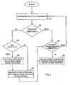
- a flow chart for a method of providing the shuttle 20 in various channels 14 of the channel store 10 is shown.
- a shuttle 20 is moved to a shuttle station 30.
- the station 30 is decoupled from a transfer station 68 of a first channel 14 on the shelf 12, preferably by lifting and / or pulling out of the station 30 by means of a stacker crane or a stacker 20.
- a step S3 is the with the shuttle 22 equipped station 30 with the stacker crane or the stacker 20 (rack truck) implemented in another transfer point 68 of another channel 14 or used.
- Fig. 8 shows a perspective view of another embodiment of a station 30 'according to the invention.
- the station 30 ' is constructed substantially the same as the station 30.
- the rail sections 36, 36 'of Fig. 8 represent only fractions, with an inner contour 80 of the rail sections 36, 36 ', the in Fig. 8 is shown with a dashed line, an inner contour of the shelf rails 58 substantially corresponds.
- a shelf rail 58 'indicated by a dotted line see also Fig. 10 ).
- the length of the rail sections 36, 36 ' is greatly shortened in the Z direction. Both on the left side and on the right side of the frame in each case two rail sections 36 and 36 'are provided.
- the transverse struts 34 are in turn connected to the struts 46, 46 'of the settler.
- the rail sections 36, 36 ' are constructed in several parts.
- square tubes are used here.
- the square tubes are welded here on connecting bars 84.
- the connecting bars 84 further provide a connection between the rail sections 36, 36 'and the transverse struts 34 and the Absetzstreben 46, 46'
- the connecting iron 84 are each angled in their lower portions at an angle ⁇ with respect to their upper portions. This angling facilitates a loading of the station 30 'into a correspondingly adapted channel 14 (cf. Fig. 11 ).
- the station 30 'tapers in this sense funnel-shaped down, so that an insertion or lifting in shelf rails 58' (see Fig. 10 ) is easy to do.
- the angled, lower parts of the connecting iron 84 lead the station 30 'when lifting.
- Fig. 9 shows the station 30 'the Fig. 8 in a perspective bottom view, with a shuttle 22 is parked in the station 30 '.
- the shuttle 22 sits with its underside 86 on the running surfaces 62 of the rail sections 36, 36 '.
- the station 30 ' is shown in an excavated position, with the forks of the stacker 20, which is normally inserted through an opening 86 of the stopper plate 40 along the settler 46, 46' below the station 30 ', are not shown.
- the station 30 ' is lifted into a channel 14
- guidance is made through the angled elements of the connecting bars 84 along the receiving rails 70, as discussed below in connection with FIGS Fig. 10 and 11 will be described in more detail.
- Fig. 9 also the sensor devices 42 'of the shuttle 22 are shown, which allow a beam path in the direction of the depth of the channel 14 (Z-direction).
- Fig. 10 shows a further embodiment of a transfer station 88, which is suitable for receiving the station 30 ', and similar to the transfer station 68 of Fig. 3 is trained.
- the transfer station 88 has fragmental shelf rails 58 'and 58 "with storage surfaces 60' and treads 62 'in addition to the storage rails 70.
- the shelf rails 58' and 58" are mounted to the storage rails 70 so as to constitute a continuation of the shelf rail 58 , This continuation is interrupted by gaps 90.
- the gaps 90 serve to receive the rail sections 36, 36 'of the shuttle 22.
- Fig. 11 the train station is 30 'the Fig. 8 and 9 in the transfer place 88 of the Fig. 10 levied. It will be appreciated that the rail portions 36 and the shelf rail fragments 58 'and 58 "are substantially a seamless continuation of the shelf rail 58. It is understood that there are smaller gaps between the shelf rails and the rail portions, these gaps become a play when lifting the railroad station 30 'in the transfer station 88 required.
- the in the 8 to 11 shown station 30 ' is preferably used at an opposite channel end, when the station 30 is inserted at the other end.
- the station 30 ' may also remain on the shelf 12 to prevent falling out of the shuttle 22 at any time. It is understood that the station 30 'is suitable for the permanent storage of a load carrier 18 and thus represents a regular storage space in the channel 14.
Landscapes
- Engineering & Computer Science (AREA)
- Mechanical Engineering (AREA)
- Warehouses Or Storage Devices (AREA)
Priority Applications (1)
| Application Number | Priority Date | Filing Date | Title |
|---|---|---|---|
| PL08874093T PL2268562T3 (pl) | 2008-04-30 | 2008-12-23 | Stacja wózkowa i wózkowy magazyn kanałowy |
Applications Claiming Priority (2)
| Application Number | Priority Date | Filing Date | Title |
|---|---|---|---|
| DE102008022323A DE102008022323A1 (de) | 2008-04-30 | 2008-04-30 | Shuttle-Kanallager, Shuttle-Bahnhof, Shuttle und Verfahren zum Betreiben des Shuttle-Kanallagers |
| PCT/EP2008/011086 WO2009132687A1 (de) | 2008-04-30 | 2008-12-23 | Shuttle-kanallager, shuttle-bahnhof, shuttle und verfahren zum betreiben des shuttle-kanallagers |
Publications (2)
| Publication Number | Publication Date |
|---|---|
| EP2268562A1 EP2268562A1 (de) | 2011-01-05 |
| EP2268562B1 true EP2268562B1 (de) | 2013-05-29 |
Family
ID=40373502
Family Applications (1)
| Application Number | Title | Priority Date | Filing Date |
|---|---|---|---|
| EP08874093.1A Not-in-force EP2268562B1 (de) | 2008-04-30 | 2008-12-23 | Shuttle-bahnhof und shuttle-kanallager |
Country Status (6)
| Country | Link |
|---|---|
| EP (1) | EP2268562B1 (pl) |
| DE (1) | DE102008022323A1 (pl) |
| DK (1) | DK2268562T3 (pl) |
| ES (1) | ES2413861T3 (pl) |
| PL (1) | PL2268562T3 (pl) |
| WO (1) | WO2009132687A1 (pl) |
Cited By (1)
| Publication number | Priority date | Publication date | Assignee | Title |
|---|---|---|---|---|
| DE102023129250A1 (de) * | 2023-10-24 | 2025-04-24 | Ro-Ber Industrieroboter Gmbh | Flächenportal zur Kommissionierung von Paletten |
Families Citing this family (23)
| Publication number | Priority date | Publication date | Assignee | Title |
|---|---|---|---|---|
| DE102009049563B4 (de) * | 2009-10-09 | 2013-04-18 | SSI Schäfer AG | Shuttle-Kanallager, Shuttle-Bahnhof, Shuttle und Verfahren zum Betreiben des Shuttle-Kanallagers |
| DE102010005591A1 (de) * | 2010-01-22 | 2011-07-28 | Koruna-Lc S.R.O. | Hochregallager zur Lagerung von Paletten, Regalbediengerät, Tandemshuttle, Übergaberegal sowie Verfahren zur Lagerung von Paletten in dem Hochregallager |
| CH702765A2 (de) | 2010-02-26 | 2011-08-31 | Stoecklin Logistik Ag | Regalbedienvorrichtung. |
| DE102010029563B4 (de) * | 2010-06-01 | 2012-12-06 | Bito-Lagertechnik Bittmann Gmbh | Kanallager |
| ITBG20110011U1 (it) * | 2011-03-21 | 2012-09-22 | Automha S R L | Impianto automatico di stoccaggio. |
| MX345209B (es) * | 2011-11-20 | 2017-01-20 | Illinois Tool Works | Sistema y métodos de almacenamiento. |
| DE202014102274U1 (de) | 2014-05-14 | 2014-06-16 | SSI Schäfer AG | Folienerkennung und Palettentyperkennung mittels Kanalfahrzeug in einem Kanalregallager |
| DE102017112669A1 (de) * | 2017-06-08 | 2018-12-13 | Claus Henkel | Modulares Lager-Regalsystem |
| EP3431418B8 (en) | 2017-07-20 | 2020-04-01 | Mikhail Voloskov | Shuttle for use in a three-dimensional warehouse system |
| EP3431416B1 (en) | 2017-07-20 | 2020-04-08 | Mikhail Voloskov | Three-dimensional warehouse system |
| CN107826580A (zh) * | 2017-11-22 | 2018-03-23 | 江苏高科物流科技股份有限公司 | 一种穿梭车式仓储以及攀爬式穿梭车 |
| CN110171656A (zh) * | 2019-05-13 | 2019-08-27 | 上海忍诚科技有限公司 | 一种用于仓储系统的立体轨道 |
| DE102019134684A1 (de) * | 2019-12-17 | 2021-06-17 | Texmato Tec Gmbh | Einfahrregalanlage |
| CN111703793B (zh) * | 2020-05-21 | 2021-12-24 | 深圳格兰达智能装备股份有限公司 | 一种智能存取系统 |
| DE102020115619A1 (de) | 2020-06-12 | 2021-12-16 | Dematic Gmbh | Warenlager- und Auftragserfüllungssystem |
| DE102020122204A1 (de) | 2020-08-25 | 2022-03-03 | Jungheinrich Aktiengesellschaft | System mit einem Regalshuttlefahrzeug und einem Lagerregal |
| DE102020122390A1 (de) * | 2020-08-27 | 2022-03-03 | Rocket Solution Gmbh | Vorrichtung zur Sicherung eines Shuttles, Shuttle und Regalsystem |
| DE102021006362B4 (de) | 2021-12-28 | 2024-04-04 | Gebhardt Fördertechnik GmbH | Zentrierstation und Verfahren zum Handhaben zumindest eines Ladungsträgers |
| EP4245697A1 (en) | 2022-03-15 | 2023-09-20 | VOLUME Lagersysteme GmbH | Shuttle for use in a three-dimensional warehouse system |
| EP4279418A1 (en) | 2022-05-16 | 2023-11-22 | VOLUME Lagersysteme GmbH | Method for retrieving goods in a warehouse system, and warehouse system |
| CN114890031A (zh) * | 2022-05-25 | 2022-08-12 | 东杰智能科技集团股份有限公司 | 高密度智能仓储系统中穿梭车的移载定位方法 |
| DE102022121352A1 (de) * | 2022-08-24 | 2024-02-29 | Gebhardt Fördertechnik GmbH | Übergabestation für einen Ladungsträger sowie Verfahren zur Übergabe eines Ladungsträgers |
| DE102022124753A1 (de) * | 2022-09-27 | 2024-03-28 | Gebhardt Fördertechnik GmbH | Shuttle-System und Verfahren zum Handhaben eines Ladungsträgers |
Family Cites Families (8)
| Publication number | Priority date | Publication date | Assignee | Title |
|---|---|---|---|---|
| US3746189A (en) * | 1966-04-18 | 1973-07-17 | Clark Equipment Co | Automatic control system for storage systems transfer cart |
| US3800963A (en) * | 1972-12-04 | 1974-04-02 | E Holland | Material storage and handling system |
| DE2930569A1 (de) * | 1979-07-27 | 1981-02-19 | Friedhelm Krups Fa | Beschickungsanlage fuer ein lager |
| IT1136819B (it) * | 1981-03-13 | 1986-09-03 | Finsider Costr Metall Cmf | Dispositivo trasportatore per un impianto di magazzinaggio |
| DE3840648A1 (de) * | 1988-12-02 | 1990-06-07 | S Way Ag | Hochregallager-einrichtung |
| DE19628123A1 (de) * | 1996-07-12 | 1998-01-15 | Maurus Dipl Ing Oehmann | Personenschutz in Regallagern |
| SE524269C2 (sv) | 2002-10-14 | 2004-07-20 | Eab Ab | Skenanordning |
| DE202007003447U1 (de) * | 2007-03-06 | 2007-05-10 | Man, Gerardus De | Kleinteilelager |
-
2008
- 2008-04-30 DE DE102008022323A patent/DE102008022323A1/de not_active Withdrawn
- 2008-12-23 EP EP08874093.1A patent/EP2268562B1/de not_active Not-in-force
- 2008-12-23 PL PL08874093T patent/PL2268562T3/pl unknown
- 2008-12-23 ES ES08874093T patent/ES2413861T3/es active Active
- 2008-12-23 WO PCT/EP2008/011086 patent/WO2009132687A1/de not_active Ceased
- 2008-12-23 DK DK08874093.1T patent/DK2268562T3/da active
Cited By (2)
| Publication number | Priority date | Publication date | Assignee | Title |
|---|---|---|---|---|
| DE102023129250A1 (de) * | 2023-10-24 | 2025-04-24 | Ro-Ber Industrieroboter Gmbh | Flächenportal zur Kommissionierung von Paletten |
| WO2025087647A1 (de) | 2023-10-24 | 2025-05-01 | Ro-Ber Industrieroboter Gmbh | Flächenportal zur kommissionierung von paletten |
Also Published As
| Publication number | Publication date |
|---|---|
| DK2268562T3 (da) | 2013-08-19 |
| DE102008022323A1 (de) | 2009-11-12 |
| ES2413861T3 (es) | 2013-07-17 |
| PL2268562T3 (pl) | 2013-10-31 |
| WO2009132687A1 (de) | 2009-11-05 |
| EP2268562A1 (de) | 2011-01-05 |
Similar Documents
| Publication | Publication Date | Title |
|---|---|---|
| EP2268562A1 (de) | Shuttle-kanallager, shuttle-bahnhof, shuttle und verfahren zum betreiben des shuttle-kanallagers | |
| DE102009049563B4 (de) | Shuttle-Kanallager, Shuttle-Bahnhof, Shuttle und Verfahren zum Betreiben des Shuttle-Kanallagers | |
| AT512339B1 (de) | Regallagersystem und verfahren zum betreiben desselben | |
| EP3183190B1 (de) | Lager- und/oder kommissioniersysteme | |
| EP3107860B1 (de) | Verfahren und vorrichtung zum ein- und auslagern oder umlagern von containern in hochregallagern | |
| EP1695925B1 (de) | Regallager und Verfahren zum Umlagern von Lagergut bei einem Regallager | |
| EP0656980B1 (de) | Vorrichtung zum raumsparenden abstellen von kraftfahrzeugen | |
| EP2404848B1 (de) | Wagen für einen schienengebundenen Transport von Paletten in einem Tiefen-Regalsystem | |
| DE102008019404B4 (de) | Artikelvereinzelung direkt in Regalbediengerät | |
| EP2648997B1 (de) | Universelles lastaufnahmemittel für palettenlose handhabung von paletten-ladegütern | |
| AT511137A1 (de) | Regallagersystem und verfahren zum betreiben desselben | |
| DE102010028821B4 (de) | Verfahren zum Be- und Entladen von Fahrzeugen sowie Logistiksysteme mit Übergabestation | |
| WO2022184925A1 (de) | Regalbediensystem, hochregallager, einlagerungsverfahren und auslagerungsverfahren | |
| EP0608689B1 (de) | Transporteinrichtung mit wenigstens einem Regalbediengerät zur Entnahme und Eingabe einer Last in Fächer von Regalen | |
| DE102016101674B4 (de) | Wabenlager sowie Kommissioniereinrichtung und Kommissionierwagen für ein Wabenlager | |
| WO2022184924A1 (de) | Regalbediensystem | |
| EP1882648B1 (de) | Verfahren zum Ein- und Auslagern von Stückgütern, insbesondere von Getränkekisten, und Lagersystem hierfür | |
| DE102007029308A1 (de) | Automatisches Handling von Mehrfachlagergutträgern | |
| DE602005004767T2 (de) | Vorrichtung und Verfahren zum Lagern von sperriger Last | |
| DE3613904C2 (pl) | ||
| EP1357061B1 (de) | Lagerfahrzeug und Regalfahrzeug mit einem derartigen Lagerfahrzeug | |
| EP0263988B1 (de) | Regalanordnung | |
| DE102015115323A1 (de) | Regalbediengerät | |
| EP4442936A1 (de) | Sattelaufliegerhochregallager und regalbediengerät | |
| EP0941949B1 (de) | Regallageranlage zur Aufnahme von Rolluntersätzen sowie Rolluntersatz für eine Regallageranlage |
Legal Events
| Date | Code | Title | Description |
|---|---|---|---|
| PUAI | Public reference made under article 153(3) epc to a published international application that has entered the european phase |
Free format text: ORIGINAL CODE: 0009012 |
|
| 17P | Request for examination filed |
Effective date: 20101011 |
|
| AK | Designated contracting states |
Kind code of ref document: A1 Designated state(s): AT BE BG CH CY CZ DE DK EE ES FI FR GB GR HR HU IE IS IT LI LT LU LV MC MT NL NO PL PT RO SE SI SK TR |
|
| AX | Request for extension of the european patent |
Extension state: AL BA MK RS |
|
| DAX | Request for extension of the european patent (deleted) | ||
| 17Q | First examination report despatched |
Effective date: 20120104 |
|
| GRAP | Despatch of communication of intention to grant a patent |
Free format text: ORIGINAL CODE: EPIDOSNIGR1 |
|
| GRAS | Grant fee paid |
Free format text: ORIGINAL CODE: EPIDOSNIGR3 |
|
| GRAA | (expected) grant |
Free format text: ORIGINAL CODE: 0009210 |
|
| AK | Designated contracting states |
Kind code of ref document: B1 Designated state(s): AT BE BG CH CY CZ DE DK EE ES FI FR GB GR HR HU IE IS IT LI LT LU LV MC MT NL NO PL PT RO SE SI SK TR |
|
| REG | Reference to a national code |
Ref country code: GB Ref legal event code: FG4D Free format text: NOT ENGLISH |
|
| REG | Reference to a national code |
Ref country code: CH Ref legal event code: NV Representative=s name: WITTE,WELLER AND PARTNER, DE Ref country code: CH Ref legal event code: EP |
|
| REG | Reference to a national code |
Ref country code: AT Ref legal event code: REF Ref document number: 614255 Country of ref document: AT Kind code of ref document: T Effective date: 20130615 |
|
| REG | Reference to a national code |
Ref country code: IE Ref legal event code: FG4D Free format text: LANGUAGE OF EP DOCUMENT: GERMAN |
|
| REG | Reference to a national code |
Ref country code: ES Ref legal event code: FG2A Ref document number: 2413861 Country of ref document: ES Kind code of ref document: T3 Effective date: 20130717 |
|
| REG | Reference to a national code |
Ref country code: DE Ref legal event code: R096 Ref document number: 502008010043 Country of ref document: DE Effective date: 20130725 |
|
| REG | Reference to a national code |
Ref country code: DK Ref legal event code: T3 |
|
| REG | Reference to a national code |
Ref country code: NL Ref legal event code: T3 |
|
| REG | Reference to a national code |
Ref country code: SE Ref legal event code: TRGR |
|
| REG | Reference to a national code |
Ref country code: LT Ref legal event code: MG4D |
|
| PG25 | Lapsed in a contracting state [announced via postgrant information from national office to epo] |
Ref country code: NO Free format text: LAPSE BECAUSE OF FAILURE TO SUBMIT A TRANSLATION OF THE DESCRIPTION OR TO PAY THE FEE WITHIN THE PRESCRIBED TIME-LIMIT Effective date: 20130829 Ref country code: LT Free format text: LAPSE BECAUSE OF FAILURE TO SUBMIT A TRANSLATION OF THE DESCRIPTION OR TO PAY THE FEE WITHIN THE PRESCRIBED TIME-LIMIT Effective date: 20130529 Ref country code: FI Free format text: LAPSE BECAUSE OF FAILURE TO SUBMIT A TRANSLATION OF THE DESCRIPTION OR TO PAY THE FEE WITHIN THE PRESCRIBED TIME-LIMIT Effective date: 20130529 Ref country code: IS Free format text: LAPSE BECAUSE OF FAILURE TO SUBMIT A TRANSLATION OF THE DESCRIPTION OR TO PAY THE FEE WITHIN THE PRESCRIBED TIME-LIMIT Effective date: 20130929 Ref country code: PT Free format text: LAPSE BECAUSE OF FAILURE TO SUBMIT A TRANSLATION OF THE DESCRIPTION OR TO PAY THE FEE WITHIN THE PRESCRIBED TIME-LIMIT Effective date: 20130930 Ref country code: SI Free format text: LAPSE BECAUSE OF FAILURE TO SUBMIT A TRANSLATION OF THE DESCRIPTION OR TO PAY THE FEE WITHIN THE PRESCRIBED TIME-LIMIT Effective date: 20130529 Ref country code: GR Free format text: LAPSE BECAUSE OF FAILURE TO SUBMIT A TRANSLATION OF THE DESCRIPTION OR TO PAY THE FEE WITHIN THE PRESCRIBED TIME-LIMIT Effective date: 20130830 |
|
| REG | Reference to a national code |
Ref country code: PL Ref legal event code: T3 |
|
| PG25 | Lapsed in a contracting state [announced via postgrant information from national office to epo] |
Ref country code: BG Free format text: LAPSE BECAUSE OF FAILURE TO SUBMIT A TRANSLATION OF THE DESCRIPTION OR TO PAY THE FEE WITHIN THE PRESCRIBED TIME-LIMIT Effective date: 20130829 Ref country code: HR Free format text: LAPSE BECAUSE OF FAILURE TO SUBMIT A TRANSLATION OF THE DESCRIPTION OR TO PAY THE FEE WITHIN THE PRESCRIBED TIME-LIMIT Effective date: 20130529 |
|
| PG25 | Lapsed in a contracting state [announced via postgrant information from national office to epo] |
Ref country code: LV Free format text: LAPSE BECAUSE OF FAILURE TO SUBMIT A TRANSLATION OF THE DESCRIPTION OR TO PAY THE FEE WITHIN THE PRESCRIBED TIME-LIMIT Effective date: 20130529 |
|
| PG25 | Lapsed in a contracting state [announced via postgrant information from national office to epo] |
Ref country code: EE Free format text: LAPSE BECAUSE OF FAILURE TO SUBMIT A TRANSLATION OF THE DESCRIPTION OR TO PAY THE FEE WITHIN THE PRESCRIBED TIME-LIMIT Effective date: 20130529 Ref country code: SK Free format text: LAPSE BECAUSE OF FAILURE TO SUBMIT A TRANSLATION OF THE DESCRIPTION OR TO PAY THE FEE WITHIN THE PRESCRIBED TIME-LIMIT Effective date: 20130529 |
|
| REG | Reference to a national code |
Ref country code: CH Ref legal event code: PFA Owner name: SSI SCHAEFER AG, CH Free format text: FORMER OWNER: SSI SCHAEFER AG, CH |
|
| PG25 | Lapsed in a contracting state [announced via postgrant information from national office to epo] |
Ref country code: RO Free format text: LAPSE BECAUSE OF FAILURE TO SUBMIT A TRANSLATION OF THE DESCRIPTION OR TO PAY THE FEE WITHIN THE PRESCRIBED TIME-LIMIT Effective date: 20130529 |
|
| PLBE | No opposition filed within time limit |
Free format text: ORIGINAL CODE: 0009261 |
|
| STAA | Information on the status of an ep patent application or granted ep patent |
Free format text: STATUS: NO OPPOSITION FILED WITHIN TIME LIMIT |
|
| 26N | No opposition filed |
Effective date: 20140303 |
|
| REG | Reference to a national code |
Ref country code: DE Ref legal event code: R097 Ref document number: 502008010043 Country of ref document: DE Effective date: 20140303 |
|
| PG25 | Lapsed in a contracting state [announced via postgrant information from national office to epo] |
Ref country code: LU Free format text: LAPSE BECAUSE OF FAILURE TO SUBMIT A TRANSLATION OF THE DESCRIPTION OR TO PAY THE FEE WITHIN THE PRESCRIBED TIME-LIMIT Effective date: 20131223 Ref country code: MC Free format text: LAPSE BECAUSE OF FAILURE TO SUBMIT A TRANSLATION OF THE DESCRIPTION OR TO PAY THE FEE WITHIN THE PRESCRIBED TIME-LIMIT Effective date: 20130529 |
|
| REG | Reference to a national code |
Ref country code: IE Ref legal event code: MM4A |
|
| PG25 | Lapsed in a contracting state [announced via postgrant information from national office to epo] |
Ref country code: IE Free format text: LAPSE BECAUSE OF NON-PAYMENT OF DUE FEES Effective date: 20131223 |
|
| PG25 | Lapsed in a contracting state [announced via postgrant information from national office to epo] |
Ref country code: CY Free format text: LAPSE BECAUSE OF FAILURE TO SUBMIT A TRANSLATION OF THE DESCRIPTION OR TO PAY THE FEE WITHIN THE PRESCRIBED TIME-LIMIT Effective date: 20130529 Ref country code: TR Free format text: LAPSE BECAUSE OF FAILURE TO SUBMIT A TRANSLATION OF THE DESCRIPTION OR TO PAY THE FEE WITHIN THE PRESCRIBED TIME-LIMIT Effective date: 20130529 |
|
| PG25 | Lapsed in a contracting state [announced via postgrant information from national office to epo] |
Ref country code: HU Free format text: LAPSE BECAUSE OF FAILURE TO SUBMIT A TRANSLATION OF THE DESCRIPTION OR TO PAY THE FEE WITHIN THE PRESCRIBED TIME-LIMIT; INVALID AB INITIO Effective date: 20081223 |
|
| PG25 | Lapsed in a contracting state [announced via postgrant information from national office to epo] |
Ref country code: MT Free format text: LAPSE BECAUSE OF FAILURE TO SUBMIT A TRANSLATION OF THE DESCRIPTION OR TO PAY THE FEE WITHIN THE PRESCRIBED TIME-LIMIT Effective date: 20130529 |
|
| REG | Reference to a national code |
Ref country code: FR Ref legal event code: PLFP Year of fee payment: 8 |
|
| PGFP | Annual fee paid to national office [announced via postgrant information from national office to epo] |
Ref country code: DK Payment date: 20151221 Year of fee payment: 8 Ref country code: GB Payment date: 20151221 Year of fee payment: 8 |
|
| PGFP | Annual fee paid to national office [announced via postgrant information from national office to epo] |
Ref country code: SE Payment date: 20151221 Year of fee payment: 8 Ref country code: FR Payment date: 20151221 Year of fee payment: 8 Ref country code: AT Payment date: 20151222 Year of fee payment: 8 Ref country code: PL Payment date: 20151130 Year of fee payment: 8 Ref country code: CZ Payment date: 20151222 Year of fee payment: 8 |
|
| PG25 | Lapsed in a contracting state [announced via postgrant information from national office to epo] |
Ref country code: CZ Free format text: LAPSE BECAUSE OF NON-PAYMENT OF DUE FEES Effective date: 20161223 |
|
| REG | Reference to a national code |
Ref country code: DK Ref legal event code: EBP Effective date: 20161231 |
|
| REG | Reference to a national code |
Ref country code: SE Ref legal event code: EUG |
|
| REG | Reference to a national code |
Ref country code: AT Ref legal event code: MM01 Ref document number: 614255 Country of ref document: AT Kind code of ref document: T Effective date: 20161223 |
|
| GBPC | Gb: european patent ceased through non-payment of renewal fee |
Effective date: 20161223 |
|
| PG25 | Lapsed in a contracting state [announced via postgrant information from national office to epo] |
Ref country code: SE Free format text: LAPSE BECAUSE OF NON-PAYMENT OF DUE FEES Effective date: 20161224 |
|
| REG | Reference to a national code |
Ref country code: FR Ref legal event code: ST Effective date: 20170831 |
|
| PG25 | Lapsed in a contracting state [announced via postgrant information from national office to epo] |
Ref country code: AT Free format text: LAPSE BECAUSE OF NON-PAYMENT OF DUE FEES Effective date: 20161223 Ref country code: FR Free format text: LAPSE BECAUSE OF NON-PAYMENT OF DUE FEES Effective date: 20170102 |
|
| PG25 | Lapsed in a contracting state [announced via postgrant information from national office to epo] |
Ref country code: GB Free format text: LAPSE BECAUSE OF NON-PAYMENT OF DUE FEES Effective date: 20161223 |
|
| PG25 | Lapsed in a contracting state [announced via postgrant information from national office to epo] |
Ref country code: DK Free format text: LAPSE BECAUSE OF NON-PAYMENT OF DUE FEES Effective date: 20161231 |
|
| PGFP | Annual fee paid to national office [announced via postgrant information from national office to epo] |
Ref country code: NL Payment date: 20171219 Year of fee payment: 10 |
|
| PGFP | Annual fee paid to national office [announced via postgrant information from national office to epo] |
Ref country code: BE Payment date: 20171219 Year of fee payment: 10 Ref country code: CH Payment date: 20171220 Year of fee payment: 10 |
|
| REG | Reference to a national code |
Ref country code: CH Ref legal event code: NV Representative=s name: TROESCH SCHEIDEGGER WERNER AG, CH |
|
| PG25 | Lapsed in a contracting state [announced via postgrant information from national office to epo] |
Ref country code: PL Free format text: LAPSE BECAUSE OF NON-PAYMENT OF DUE FEES Effective date: 20161223 |
|
| PGFP | Annual fee paid to national office [announced via postgrant information from national office to epo] |
Ref country code: DE Payment date: 20180206 Year of fee payment: 10 Ref country code: ES Payment date: 20180124 Year of fee payment: 10 |
|
| PGFP | Annual fee paid to national office [announced via postgrant information from national office to epo] |
Ref country code: IT Payment date: 20171221 Year of fee payment: 10 |
|
| REG | Reference to a national code |
Ref country code: DE Ref legal event code: R119 Ref document number: 502008010043 Country of ref document: DE |
|
| REG | Reference to a national code |
Ref country code: CH Ref legal event code: PL |
|
| REG | Reference to a national code |
Ref country code: NL Ref legal event code: MM Effective date: 20190101 |
|
| PG25 | Lapsed in a contracting state [announced via postgrant information from national office to epo] |
Ref country code: NL Free format text: LAPSE BECAUSE OF NON-PAYMENT OF DUE FEES Effective date: 20190101 |
|
| REG | Reference to a national code |
Ref country code: BE Ref legal event code: MM Effective date: 20181231 |
|
| PG25 | Lapsed in a contracting state [announced via postgrant information from national office to epo] |
Ref country code: IT Free format text: LAPSE BECAUSE OF NON-PAYMENT OF DUE FEES Effective date: 20181223 Ref country code: DE Free format text: LAPSE BECAUSE OF NON-PAYMENT OF DUE FEES Effective date: 20190702 |
|
| PG25 | Lapsed in a contracting state [announced via postgrant information from national office to epo] |
Ref country code: BE Free format text: LAPSE BECAUSE OF NON-PAYMENT OF DUE FEES Effective date: 20181231 |
|
| PG25 | Lapsed in a contracting state [announced via postgrant information from national office to epo] |
Ref country code: CH Free format text: LAPSE BECAUSE OF NON-PAYMENT OF DUE FEES Effective date: 20181231 Ref country code: LI Free format text: LAPSE BECAUSE OF NON-PAYMENT OF DUE FEES Effective date: 20181231 |
|
| REG | Reference to a national code |
Ref country code: ES Ref legal event code: FD2A Effective date: 20200205 |
|
| PG25 | Lapsed in a contracting state [announced via postgrant information from national office to epo] |
Ref country code: ES Free format text: LAPSE BECAUSE OF NON-PAYMENT OF DUE FEES Effective date: 20181224 |