EP2268125B1 - Vorrichtung und verfahren zur wachstumsbeschleunigung und regeneration von rasenflächen - Google Patents
Vorrichtung und verfahren zur wachstumsbeschleunigung und regeneration von rasenflächen Download PDFInfo
- Publication number
- EP2268125B1 EP2268125B1 EP08873845.5A EP08873845A EP2268125B1 EP 2268125 B1 EP2268125 B1 EP 2268125B1 EP 08873845 A EP08873845 A EP 08873845A EP 2268125 B1 EP2268125 B1 EP 2268125B1
- Authority
- EP
- European Patent Office
- Prior art keywords
- lawn
- housing
- gas
- space
- tent
- Prior art date
- Legal status (The legal status is an assumption and is not a legal conclusion. Google has not performed a legal analysis and makes no representation as to the accuracy of the status listed.)
- Revoked
Links
Images


Classifications
-
- A—HUMAN NECESSITIES
- A01—AGRICULTURE; FORESTRY; ANIMAL HUSBANDRY; HUNTING; TRAPPING; FISHING
- A01G—HORTICULTURE; CULTIVATION OF VEGETABLES, FLOWERS, RICE, FRUIT, VINES, HOPS OR SEAWEED; FORESTRY; WATERING
- A01G9/00—Cultivation in receptacles, forcing-frames or greenhouses; Edging for beds, lawn or the like
- A01G9/14—Greenhouses
- A01G9/16—Dismountable or portable greenhouses ; Greenhouses with sliding roofs
-
- A—HUMAN NECESSITIES
- A01—AGRICULTURE; FORESTRY; ANIMAL HUSBANDRY; HUNTING; TRAPPING; FISHING
- A01G—HORTICULTURE; CULTIVATION OF VEGETABLES, FLOWERS, RICE, FRUIT, VINES, HOPS OR SEAWEED; FORESTRY; WATERING
- A01G20/00—Cultivation of turf, lawn or the like; Apparatus or methods therefor
-
- A—HUMAN NECESSITIES
- A01—AGRICULTURE; FORESTRY; ANIMAL HUSBANDRY; HUNTING; TRAPPING; FISHING
- A01G—HORTICULTURE; CULTIVATION OF VEGETABLES, FLOWERS, RICE, FRUIT, VINES, HOPS OR SEAWEED; FORESTRY; WATERING
- A01G7/00—Botany in general
- A01G7/04—Electric or magnetic or acoustic treatment of plants for promoting growth
-
- A—HUMAN NECESSITIES
- A01—AGRICULTURE; FORESTRY; ANIMAL HUSBANDRY; HUNTING; TRAPPING; FISHING
- A01G—HORTICULTURE; CULTIVATION OF VEGETABLES, FLOWERS, RICE, FRUIT, VINES, HOPS OR SEAWEED; FORESTRY; WATERING
- A01G9/00—Cultivation in receptacles, forcing-frames or greenhouses; Edging for beds, lawn or the like
- A01G9/24—Devices or systems for heating, ventilating, regulating temperature, illuminating, or watering, in greenhouses, forcing-frames, or the like
- A01G9/249—Lighting means
-
- A—HUMAN NECESSITIES
- A01—AGRICULTURE; FORESTRY; ANIMAL HUSBANDRY; HUNTING; TRAPPING; FISHING
- A01G—HORTICULTURE; CULTIVATION OF VEGETABLES, FLOWERS, RICE, FRUIT, VINES, HOPS OR SEAWEED; FORESTRY; WATERING
- A01G7/00—Botany in general
- A01G7/04—Electric or magnetic or acoustic treatment of plants for promoting growth
- A01G7/045—Electric or magnetic or acoustic treatment of plants for promoting growth with electric lighting
-
- Y—GENERAL TAGGING OF NEW TECHNOLOGICAL DEVELOPMENTS; GENERAL TAGGING OF CROSS-SECTIONAL TECHNOLOGIES SPANNING OVER SEVERAL SECTIONS OF THE IPC; TECHNICAL SUBJECTS COVERED BY FORMER USPC CROSS-REFERENCE ART COLLECTIONS [XRACs] AND DIGESTS
- Y02—TECHNOLOGIES OR APPLICATIONS FOR MITIGATION OR ADAPTATION AGAINST CLIMATE CHANGE
- Y02A—TECHNOLOGIES FOR ADAPTATION TO CLIMATE CHANGE
- Y02A40/00—Adaptation technologies in agriculture, forestry, livestock or agroalimentary production
- Y02A40/10—Adaptation technologies in agriculture, forestry, livestock or agroalimentary production in agriculture
- Y02A40/25—Greenhouse technology, e.g. cooling systems therefor
-
- Y—GENERAL TAGGING OF NEW TECHNOLOGICAL DEVELOPMENTS; GENERAL TAGGING OF CROSS-SECTIONAL TECHNOLOGIES SPANNING OVER SEVERAL SECTIONS OF THE IPC; TECHNICAL SUBJECTS COVERED BY FORMER USPC CROSS-REFERENCE ART COLLECTIONS [XRACs] AND DIGESTS
- Y02—TECHNOLOGIES OR APPLICATIONS FOR MITIGATION OR ADAPTATION AGAINST CLIMATE CHANGE
- Y02P—CLIMATE CHANGE MITIGATION TECHNOLOGIES IN THE PRODUCTION OR PROCESSING OF GOODS
- Y02P60/00—Technologies relating to agriculture, livestock or agroalimentary industries
- Y02P60/14—Measures for saving energy, e.g. in green houses
Definitions
- the invention relates to a device and a method for growth acceleration and regeneration of lawns.
- WO 95/09681 A is a system for the protection of lawns or pitches out.
- This device is a multi-segment transparent cover. It covers the entire lawn area.
- the segments are designed so that they can be placed nested at the edge of the lawn. If the innermost segment pulled out, the other segments are taken. The entire lawn is covered by opposing rows of several of these segments. Wheels are provided at the bottom of the segments.
- the innermost segment is provided with a drive device. As drive both an electric motor and an electric winch is proposed.
- the segments may have lighting devices and a heating device.
- a mobile structure for covering a lawn comprises a plurality of telescoping tent-like segments, one element being almost completely receivable in the next.
- Rollers are provided at the lower end of the segments.
- motors are provided which drive a gear arranged in the region of the rollers in order to bring the mobile structure apart in the longitudinal direction along a toothed rack.
- the device can be arranged on one side of a lawn. The drive pulls the segments apart one after the other until the device covers the lawn.
- the motor is embedded in the ground and drives via a gear on a arranged on the mobile structure rack.
- the tunnel system has a semicircular frame.
- the frame has a first base element. From the base member, a plurality of further semi-circular struts extendable to form, starting from the base member an almost arbitrarily long tunnel.
- the walls of the tunnel system are transparent.
- On the underside of the tunnel system rollers are arranged, which are rotatable by 360 °. Lighting devices can be provided on reinforcing struts extending in the longitudinal direction.
- the apparatus includes a controller to control parameters such as light, temperature and current.
- the document GB-A-2350997 describes a relatively compact small device for growth acceleration of turf, wherein the device comprises a base frame, at the corners of each of which a wheel for moving the entire device 1 is arranged on the underside.
- From the EP 0 561 193 A2 is a method and a device for growth promotion of plants or grass out.
- the device has a cover that almost completely covers the grass, light sources and two fans for introducing carbon dioxide. Under this closed cover, the grass will be exposed for about 8 to 12 hours within 24 hours using the artificial light sources.
- the atmosphere is exposed to the grass is constantly or intermittently moved by the two fans and / or replaced constantly or from time to time.
- the amount of carbon dioxide absorbed by the grass is to be supplied continuously or in time periods to the atmosphere of the room through a means for introducing carbon dioxide.
- a device for fumigation of grass surfaces is described.
- a gas flow is supplied to the lawn by a gas channel extending over a lawn.
- the gas duct is connected to a printing unit at one open end and closed at the other end. This points to a lawn area facing area Outlets on.
- sensors are provided which detect one or more measured variables, such as ambient temperature, ambient humidity, lawn temperature, grass moisture, gas inlet temperature, gas outlet temperature, inlet gas moisture, outlet gas moisture, carbon dioxide content and fertilizer content and transferred to a control and control unit with which the pressure unit and / or the supply of water vapor and / or carbon dioxide and / or fertilizer and / or a heating device can be adjusted.
- the device may also be designed as a mobile device with a chassis.
- a chassis is provided with a drive.
- the drive takes place by means of a drive chain, which runs in a drive channel.
- the drive channel is below the level of the lawn.
- the DE 10 2006 017 813 A1 discloses a method for growth acceleration and regeneration of lawns, wherein the turf surface is at least partially enclosed on the upper side by a downwardly open-sided space enclosed. CO 2 is introduced into the room and the area covered by the room is exposed to light by a lighting device. On the DE 10 2006 017 813 A1 is hereby incorporated by reference.
- the object of the invention is to provide a device and a method with which large lawns can be accelerated in growth easily and inexpensively.
- the object is achieved with a device having the features of claim 1 and by a method having the features of claim 13.
- the device according to the invention is designed for growth acceleration and regeneration of lawns. It comprises a downwardly open housing which can be erected on a lawn and delimits a space above the lawn, the housing being either transparent and / or having lighting means for illuminating the lawn.
- the housing is formed with a shuttle for automatically moving the housing on the lawn.
- the automatic process treats the lawns exactly according to pre-set parameters, resulting in a more effective and even treatment of the lawn area.
- Damage to the device due to bad weather is avoided by driving together or driving away.
- the risk of personal injury from flying around or falling devices is reduced.
- the devices 1 according to the invention are provided to accelerate the growth of a lawn 2, having a downwardly open housing for covering a portion of the lawn 4 that is moveable.
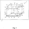
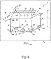
- FIG. 1 a first embodiment of the device 1 according to the invention is shown, wherein the FIG. 1 a frame structure 7 of the housing without components and FIG. 2 shows the frame structure 7 of the housing with components.
- the housing defines a space 6 above a lawn 4.
- the frame structure 7 has struts along the edges of the cuboid housing.
- the two opposite in the longitudinal direction of the housing end walls form a front wall 8 and a rear wall 9.
- the front wall 8 and the rear wall 9 have a rectangular frame 10 of two vertically and two horizontally arranged struts 11, 12, which are part of the frame structure 7 of the housing 3.
- the respective opposite upper and lower corners 13, 14 of the rectangular frame of the front and the rear wall are connected to each other via longitudinal struts 15 in the longitudinal direction.
- the longitudinal struts 15 and the vertical struts define side walls 22.
- the housing 3 or its frame structure 7 is provided in addition to the front and the rear wall 8, 9 with a roof 21 and side walls 22.
- the roof 21 is formed as a pitched roof. At the ridge of the roof, a longitudinally extending longitudinal strut 15 is arranged, which is connected to the upper corners 13 via four Gibelstreben 5.
- the walls are formed of films.
- the framework 7 and the foils form a tent.
- the slides can be transparent. This transparent film material causes a greenhouse effect in the interior of the device similar to glass in conventional greenhouses.
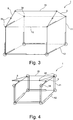
- the longitudinal struts 15 are designed to be adjustable in length. They connect the front and the rear wall 8, 9 in the longitudinal direction with each other such that the distance between the front and the rear wall 8, 9, e.g. can be varied between 0.5 m and 7 m.
- the longitudinal struts are formed ziharmonikaartig.
- connecting struts 15 in the form of telescopically extendable struts (pneumatic).
- variable longitudinal struts 15 are each provided with a locking member (not shown) in order to block them or to extend and retract them in the unlocked state.
- the locking members are connected to a control device. In the extended and collapsed state, the Connecting struts blocked via the controlled by a control device 20 locking members.
- the housing 3 forms a rigid or rigid unit, whereby it has a high stability.
- the frame structure 7 and the struts 11, 12, 15 of the housing 3 are made of a light stiff material, such as. glass fiber reinforced plastic or aluminum hollow profiles, formed.
- Both wheels 16 of the front wall 8 are each connected to a motor 17 to drive them.
- the motors 17 together with the wheels 16 is a traversing device.
- Both wheels 16 of the rear wall are rotatable about bearings 18 about a vertical axis.
- a brake 19 is provided at the wheels 16, to prevent unwanted rolling of the wheels 16 of the rear wall.
- the motors 17 and the brake 19 are connected to the controller 20.
- the driven wheels 16 can be driven to rotate the device 1 at a different speed.
- the device 1 is very manoeuvrable and can be moved exactly in the smallest space.
- the device 1 can be moved together when the wheels 16 of the rear wall 9 are blocked by the brake 19 and the front wall 8 is moved via the motors 17 in the direction of the rear wall 9.
- sensors 23 On the lower horizontal struts 12 of the front and rear walls 8, 9 and on the lower connecting struts 15 are distributed circumferentially or sensors 23 arranged to detect obstacles and / or markings.
- sensors 23 may be provided on each side of the device 1.
- a marker e.g. a wire or light signals (laser) arranged on the turf surface 2 may be provided.
- a marker e.g. a wire or light signals (laser) arranged on the turf surface 2 may be provided.
- the area to be treated can be limited and the control of the device 1 is simplified.
- sensors 23 may be provided to collide two devices 1, which are moved separately on a lawn 2 or to prevent a collision with an obstacle.
- the walls 8, 9, 21, 22 have cuffs 24 on the underside, in order to seal the space 6, which is delimited by the device 1, as gastight as possible from the environment or the lawn 2.
- a wind measuring device 25 is arranged in the upper region of the device 1 or on the roof 21 in order to measure the wind force near the device.
- the control device 20 evaluates the data recorded by the wind measuring device 25.
- the control device 20 is designed in such a way that the device 1 is moved over the grass surface 2 at a specific speed via the motors 17 or lingers there for a specific time in order to ensure the optimum treatment duration per lawn area.
- the controller 20 may collapse the device 1 to a more compact or smaller format to provide less impact surface to the wind.
- the rollers of the rear wall are blocked and the front wall 8 is moved in the direction of the rear wall 9, the overall length of the device 1 is shortened.
- the device 1 is moved into a shelter, where it is protected from damage by the wind.
- the shelter is designed such that a plurality of such devices 1 can be arranged therein at least in the contracted state.
- outflow device 26 for gas
- the outflow device 26 is, for example, a tubular structure 27, which extends over a partial length or the entire length of the space 6.
- the tube or tube-like structure 27 has outflow openings 28, from which a CO 2 gas can flow out.
- the CO 2 gas comes from a gas storage (not shown), which is connected to a corresponding supply line 29 with the tubular structure 27.
- a CO 2 measuring device or a CO 2 sensor 30 is preferably connected to the gas storage via a line 31, the control device 20 controlling the gas content. regulates.
- a lighting device 32 which consists for example of fluorescent noise, incandescent or gas discharge lamps.
- photosynthetic lamps are used, e.g. that of General Electric Comp. and sold under the trade name Lucalox PSL lamps.
- Light-emitting diodes (LED) which emit light in the wavelength range suitable for photosynthesis can also be provided as lighting device 32.
- a lawn heater 33 is present, it is within the enclosed space 6 to a circulation of the flowing out of the tube-like structure 27 and flowing downward or falling CO 2, wherein by convection at a central introduction of the CO 2 From the roof 21 ago the CO 2 flows upwards in the edge areas.
- a tube 27 is used to supply the CO 2 gas.
- a single, punctiform nozzle instead of such a tube, as is ensured by the existing space in the convection for a uniform distribution of the CO 2 gas.
- the illumination device 32 is provided at a height h of 1.40 m to 3 m, preferably 2.20 m to 2.50 m, wherein the CO 2 supply line is provided about 20 cm to 80 cm above the illumination device.
- the horizontal and the vertical struts of the front and the rear wall are designed to be variable in length.
- the device is designed to be movable together not only in length but also in the width and in the height, in order to provide a smaller surface to wind.
- the roof 21 has corresponding joints 34 on the Gibelstreben 5 and at the upper corners of the front and the rear wall 8, 9, to form the roof 21 foldable ( FIG. 4 ).
- servomotors (not shown) are provided, which are controlled by the control device 20.
- the motors 17 serve only for steering or turning and method of the device 1.
- the wheels 16 of the front wall 8 are driven by a single motor 17, which is connected via a drive shaft 50 with both wheels.
- the wheels of the front wall are connected to an actuator 51 to steer the device can.
- the wheels of the rear wall 16 are then connected to a brake 19 to block the rear wall 9 can.
- FIG. 6 In the longitudinal direction in the area in front of the front wall 8 a lawn mowing and / or Vertikutier sensible 35 is arranged.
- the lawn mowing and / or Vertikutier Ran 35 is also controlled by the control device 20 and works in particular in the method of the device 1 to maintain the lawn 4 by cutting and / or scarifying during the process in addition.
- Each device forms a segment of the train.
- Such a train covers and treats a large area when using relatively small segments.
- This also allows contoured landscapes, such as golf courses treat, because within a train an adjustment to the variable contour is done by the different inclinations of the individual segments.
- the individual segments may be hinged together so as to define a common space above the lawn.
- the individual segments or their side walls and roofs are connected to each other in a gastight manner via hoses.
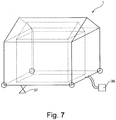
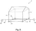
- FIG. 7 This is tent-shaped with air mattress-like inflatable walls. These can be inflated, for example via a pump 36. If the wind is too strong, the air can simply be let out of the walls. In this way, the device lies flat on the ground and no longer forms an attack surface for the wind.
- the individual walls can, for example, have individual chambers which are communicatively connected to one another in order to increase the stability of the device and which can be inflated via a pump 36 connected to the control device 20.
- the walls of the device are made of glass or plastic, such as glass.
- PMMA Polymethylmethacrylate
- acrylic glass Plexiglas®
- Limacryl® Limacryl®
- piacryl or O-glass are formed.
- lamps it is not absolutely necessary that the walls are transparent.
- the controller 20 may be connected to a satellite navigation system and / or a terrestrial navigation system.
- two cable winches 38, 39 are provided as moving devices of the device 1 instead of the motors.
- the first winch 38 is connected via a cable 40 with the lower cross member 12 of the rear wall 9.
- the second cable 41 is arranged on the lower transverse strut 12 of the front wall 8 and is deflected by a arranged on the lower cross member 12 of the rear wall 9 roller 52 so that it emerges from the device at the front end of the device 1 and the second winch 39th connected is.
- a cable winch is sufficient, if e.g. is disposed on one side of the lawn and has a loop-shaped endless rope, which is deflected by a roller on the other side of the lawn. The rope is connected to the device 1.
- One or more devices according to the invention are positioned on a lawn to be treated.
- the controller after a preset treatment time, drives the motors such that the device automatically rotates, e.g. one device length and handles a next section of the lawn.
- the coordinates by which the device is traversed can be determined either by a control routine which detects the movement of the wheels or by signals detected by sensors, e.g. be provided by a wire arranged in the lawn or a light signal or by a global navigation system.
- the treatment of the lawn provides for fumigation with CO 2 and / or treatment with light.
- the device At the onset of a storm that is strong enough to compromise or damage the operability of the device, the device is reduced to more compact dimensions.
- the control device receives the instructions that it should collapse the device, for example by evaluating the data provided by the wind measuring device.
- the wind measuring device delivers the current wind strengths directly near the device and is therefore very special well suited to provide parameters for safe operation of the device.
- the evaluation also takes into account the gustiness of the wind.
- the information for the controller may also be provided by a weather service.
- the combination can be done according to the embodiments described above.
- the wheels of the front wall are blocked by the brake and the driven wheels of the rear wall to move the rear wall in the direction of the front wall.
- the connecting struts then move together and the device has a smaller overall length.
- the device has a lower attack surface against wind and can thus remain on the lawn in most cases.
- the device can also be moved together in width and / or in height, which further reduces the attack surface.
- the device can also be moved automatically into a suitable shelter, where it is safe from bad weather.
- the device mows the lawn during the process of a Rasenmdozens- and / or Vertikutiert and scarred
- the device when a first and a second winch are arranged on opposite sides of, for example, a soccer field, the device can also be moved together.
- the rope of the second winch is blocked and pulled on the rope of the first winch.
- the rope of the first winch is attached to the lower cross strut of the front wall and we via the freely rotatable roller on the lower cross strut of the rear wall diverted.
- the front wall moves in the direction of the rear wall until the device has completely collapsed.
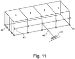
- the device 1 comprises a housing 3 with a frame structure 7, in which a plurality of housing profile frames 48 are each connected to concertina-like telescoping or extensible longitudinal struts 15.
- Each housing profile frame has two vertical struts 11 and a roof strut structure 49 extending between the two upper ends of the vertical struts.
- Each strut structure 49 has a horizontal strut 12 and two gable struts. The areas between two housing profile frames 48 each form a housing section 42.
- Each of the housing sections 42 has a length of about 5 m and a width of about 6 m. Two to five of these housing sections 42 may form a tunnel covering an area of about 150 m 2 . With eg four of these tunnels (approx. 600 m 2 ), the lawn area of a stadium (approx. 7000 m 2 ) is partially regenerated.
- the individual housing profile frame 48 of this tunnel are provided at their lower ends with wheels 16 to be mobile on the lawn 2 to be regenerated.
- the housing sections 42 In the folded state, the housing sections 42 have a length of about 80 cm and can be offset with a simple lifting machine, such as a forklift. It is also possible that the device comprises a motor for driving the wheels according to the embodiments described above.
- FIGS. 9 and 10 are several juxtaposed devices in the FIGS. 9 and 10 shown embodiment shown as a cuboid 1 schematically.
- the devices 1 are connected together to move them together.
- the connection can be made via a bar 43, for example.
- the beam 43 is connected by a cable 40 with a winch 38. By pressing this winch 38, the devices on the lawn 2 are movable.
- lighting devices 32 in the form of, for example, six lamps are present in each housing section 42.
- the lamps are specially designed for photosynthesis assimilation lamps from Philips with, for example, 600W and a degree of illumination of 100 to 200 .mu.mol / m 2 s.
- the lamps are arranged at a height h of 1.6 m to 2.0 m and preferably 1.8 m.
- the lamps increase the ambient temperature by approx. 10 ° C. This is often enough to reach a temperature of 3 ° C to 5 ° C in winter, which the lawn needs to grow.
- the device 1 according to the invention according to another embodiment, a lighting space 44 in which the lighting devices 32 are arranged, and a regeneration space 45, in which the discharge device 26 is arranged on.
- the lighting space 44 and the regeneration space 35 are separated from each other by a second ceiling wall 46, which is transparent or translucent.
- the second ceiling wall 46 closes off the regeneration space 45 in a gastight manner and is e.g. arranged about 50 cm above the ground.
- the lamps are arranged in the lighting space 44 below the ridge.
- the side walls 22 are provided with ventilation means 47, which are formed as ventilation openings 47, to dissipate the heat of the lamps.
- the entire film is formed as a transparent film, sunlight reaches the lawn, so that the lighting devices 32 can be turned off in daylight, which saves considerable energy.
- the film is preferably designed such that it is translucent from the outside and light reflected from the inside, for example by the inner surface is mirrored and the outer surface is formed matte.
- 10th and 11 embodiment shown can also be formed without subdivision of the enclosed space 6 in an illumination space 44 and a regeneration space 45.
- the CO 2 concentration is preferably between 800 ppm CO 2 and 2000 ppm CO 2 .
- the heat development of the lighting means also causes the heat development by a lawn heating, a significant increase in temperature, which is sufficient to allow the lawn forming grass plants growth.
- the tents according to the invention or built-in spaces have approximately a footprint of 10 x 30 m to 15 x 30 m or from 30 m 2 to 400 m 2 . Smaller tents are used to maintain areas that are subject to local stress, such as the area around the gate.
- system or apparatus or method will be deployed and operated at a particular location for four to twelve hours and then converted to continue operation at a next location.
Landscapes
- Life Sciences & Earth Sciences (AREA)
- Environmental Sciences (AREA)
- Biodiversity & Conservation Biology (AREA)
- Botany (AREA)
- Ecology (AREA)
- Forests & Forestry (AREA)
- Cultivation Of Plants (AREA)
- Tents Or Canopies (AREA)
Priority Applications (1)
| Application Number | Priority Date | Filing Date | Title |
|---|---|---|---|
| PL08873845T PL2268125T3 (pl) | 2008-04-11 | 2008-12-17 | Urządzenie i sposób przyspieszenia wzrostu i regeneracji powierzchni trawiastych |
Applications Claiming Priority (2)
| Application Number | Priority Date | Filing Date | Title |
|---|---|---|---|
| DE102008018459A DE102008018459A1 (de) | 2008-04-11 | 2008-04-11 | Vorrichtung und Verfahren zur Wachstumsbeschleunigung und Regeneration von Rasenflächen |
| PCT/EP2008/010780 WO2009124577A1 (de) | 2008-04-11 | 2008-12-17 | Vorrichtung und verfahren zur wachstumsbeschleunigung und regeneration von rasenflächen |
Publications (2)
| Publication Number | Publication Date |
|---|---|
| EP2268125A1 EP2268125A1 (de) | 2011-01-05 |
| EP2268125B1 true EP2268125B1 (de) | 2017-06-28 |
Family
ID=40433916
Family Applications (1)
| Application Number | Title | Priority Date | Filing Date |
|---|---|---|---|
| EP08873845.5A Revoked EP2268125B1 (de) | 2008-04-11 | 2008-12-17 | Vorrichtung und verfahren zur wachstumsbeschleunigung und regeneration von rasenflächen |
Country Status (12)
| Country | Link |
|---|---|
| US (1) | US9307703B2 (ru) |
| EP (1) | EP2268125B1 (ru) |
| AU (1) | AU2008354613B2 (ru) |
| BR (1) | BRPI0822524A2 (ru) |
| CA (1) | CA2721142C (ru) |
| DE (1) | DE102008018459A1 (ru) |
| ES (1) | ES2642064T3 (ru) |
| PL (1) | PL2268125T3 (ru) |
| RU (1) | RU2508624C2 (ru) |
| UA (1) | UA104139C2 (ru) |
| WO (1) | WO2009124577A1 (ru) |
| ZA (1) | ZA201007293B (ru) |
Families Citing this family (23)
| Publication number | Priority date | Publication date | Assignee | Title |
|---|---|---|---|---|
| DE102006017813A1 (de) * | 2006-04-13 | 2007-10-18 | Linde Ag | Verfahren und Vorrichtung zur Wachstumsbeschleunigung |
| GB0907955D0 (en) * | 2009-05-09 | 2009-06-24 | Hemstock David K | Light mesh sports turf lighting system |
| CN102002683B (zh) * | 2010-12-10 | 2012-09-05 | 厦门大学 | 一种含氢类金刚石膜的制备方法 |
| US20120216459A1 (en) * | 2011-02-28 | 2012-08-30 | David Frederick Currier | Method and apparatus for optimal enrichment of co2 for plant production |
| US20140305039A1 (en) * | 2013-04-10 | 2014-10-16 | Kip Andersen | Vertically Adjustable Organism Housing Assembly |
| JP6469548B2 (ja) | 2014-09-01 | 2019-02-13 | 昭和電工株式会社 | 天然芝育成用照明装置 |
| JP6379961B2 (ja) * | 2014-10-08 | 2018-08-29 | 株式会社大林組 | 芝育成装置 |
| US10094116B2 (en) * | 2015-01-01 | 2018-10-09 | Aravinda Raama Mawendra | Central processing horticulture |
| US11129344B2 (en) * | 2015-01-01 | 2021-09-28 | Aravinda Raama Mawendra | Central processing horticulture |
| EP3132676B1 (en) * | 2015-08-18 | 2018-01-17 | Showa Denko K.K. | Lighting apparatus for raising natural lawn grass |
| EP3146834B1 (de) | 2015-09-23 | 2020-05-13 | Seegrow (Developments) Limited | Einrichtung und verfahren zur beleuchtung von pflanzen, insbesondere rasenflächen |
| MY194833A (en) | 2015-11-09 | 2022-12-19 | Weatherford Tech Holdings Llc | Inflow control device having externally configurable flow ports and erosion resistant baffles |
| CA3047358A1 (en) * | 2015-12-21 | 2017-06-29 | RHENAC GreenTec AG | Light-emitting device and method for promoting grass growth |
| DE102016000392A1 (de) * | 2016-01-14 | 2017-07-20 | Linde Aktiengesellschaft | Vorrichtung und Verfahren zur Wachstumsbeschleunigung und Regeneration von Rasenflächer |
| US20220248679A1 (en) * | 2017-03-23 | 2022-08-11 | The Agricultural Gas Company | System for promoting plant growth and production |
| CN106950965A (zh) * | 2017-04-26 | 2017-07-14 | 华中农业大学 | 一种大田作物信息采集机器人 |
| FR3068570B1 (fr) * | 2017-07-07 | 2019-08-16 | Andre Barre | Serre agricole deplacable comportant une ossature avec arceaux reunis par au moins une entretoise de forme particuliere et une couverture dotee d'un systeme lateral d'aeration simplifie |
| DE102017215818B4 (de) * | 2017-09-07 | 2019-04-18 | Deutsches Zentrum für Luft- und Raumfahrt e.V. | Verfahren zur Verbesserung der Photosynthese von Photosynthese durchführenden Lebewesen sowie Vorrichtung zur Durchführung des Verfahrens |
| CN108705903B (zh) * | 2018-06-13 | 2020-12-18 | 山东省安正安全咨询服务有限公司 | 一种基于环境净化的智能汽车车轮系统 |
| JP7061043B2 (ja) * | 2018-07-27 | 2022-04-27 | 株式会社竹中工務店 | 天然芝育成システム |
| US11641809B2 (en) * | 2019-10-16 | 2023-05-09 | Poseidon Reef Systems LLC | Inflatable grow tent with integrated lighting |
| DE102021113166A1 (de) | 2020-05-20 | 2021-11-25 | Baumhöver Frischgeflügel GmbH & Co. KG | Mobile Vorrichtung und Verfahren |
| DE202021102774U1 (de) | 2021-05-20 | 2022-08-23 | Baumhöver Frischgeflügel GmbH & Co. KG | Mobile Vorrichtung für den mobilen Einsatz eines landwirtschaftlichenBauwerks wie eines Gewächshauses |
Citations (6)
| Publication number | Priority date | Publication date | Assignee | Title |
|---|---|---|---|---|
| DE19645723A1 (de) | 1995-11-07 | 1997-05-15 | Fuji Heavy Ind Ltd | Autonomes Fahrtsteuerungssystem und -verfahren für ein Fahrzeug |
| WO2000057689A1 (en) | 1999-03-25 | 2000-10-05 | Mobilt Drivhus As | System and method to benefit the growth conditions of grass plants entered in grass courts |
| GB2350997A (en) * | 1999-05-12 | 2000-12-20 | David Anthony Price | Outdoor grass cover improvement |
| US20010035468A1 (en) | 2000-03-20 | 2001-11-01 | Santa Cruz Cathy D. | Portable accelerated growth system for vegetation |
| DE102004019049A1 (de) | 2004-04-16 | 2005-11-17 | Universität Duisburg-Essen | Beleuchtungsvorrichtung zur Stimulation des Pfanzenwachstums |
| WO2007118662A1 (de) | 2006-04-13 | 2007-10-25 | Linde Ag | Verfahren und vorrichtung zur wachstumsbeschleunigung |
Family Cites Families (20)
| Publication number | Priority date | Publication date | Assignee | Title |
|---|---|---|---|---|
| US2575572A (en) * | 1949-11-14 | 1951-11-20 | Wickstrum Cecil Mathias | Rolling chapel tent construction |
| US4163342A (en) * | 1978-03-24 | 1979-08-07 | General Electric Company | Controlled environment agriculture facility and method for its operation |
| US4569150A (en) * | 1983-10-31 | 1986-02-11 | Board Of Trustees Operating Michigan State University | Method and apparatus for optimization of growth of plants |
| FR2555219B1 (fr) | 1983-11-23 | 1986-04-18 | Letulle Bernard | Structure mobile avec son dispositif d'entrainement |
| US4903464A (en) * | 1989-03-14 | 1990-02-27 | Debruhl Jr Ray | Overhead plant clipping system |
| SU1767138A1 (ru) * | 1990-07-02 | 1992-10-07 | Алма-Атинский институт инженеров железнодорожного транспорта | Складное сооружение |
| DE4208305A1 (de) | 1992-03-16 | 1993-09-23 | Wund Josef | Verfahren und vorrichtung zur wachstumsfoerderung von pflanzen |
| NL9301704A (nl) | 1993-10-04 | 1995-05-01 | Koot L C J Holding Bv | Systeem voor het beschermen van een terrein. |
| IL111593A (en) * | 1994-11-10 | 1999-01-26 | Biosolar Resources | Apparatus for heating a greenhouse |
| AU4422497A (en) * | 1996-09-30 | 1998-04-24 | Jaderloon Company, Inc. | Covering mechanism for a greenhouse |
| US6141902A (en) * | 1998-04-23 | 2000-11-07 | Boice; A. Parker | Knockdown portable greenhouse and kit for parcel service shipment |
| US6079152A (en) * | 1998-10-14 | 2000-06-27 | Hou; Chuwg-Chu | Greenhouse structure |
| ATE390035T1 (de) | 2001-06-20 | 2008-04-15 | Gerd Gemmel | Vorrichtung zur begasung von rasenflächen |
| RU2251066C2 (ru) * | 2003-04-03 | 2005-04-27 | ООО Научно-технический центр "Версия" | Складное укрытие (варианты) |
| US7362439B2 (en) * | 2003-08-01 | 2008-04-22 | Li-Cor, Inc. | Method of detecting the condition of a turf grass |
| US20060091234A1 (en) * | 2004-11-01 | 2006-05-04 | Wallander James J | Portable misting system |
| KR100632962B1 (ko) * | 2005-04-29 | 2006-10-12 | (주)건원산업건축사사무소 | 겹침식 셀터 시스템 |
| RU61764U1 (ru) * | 2006-08-18 | 2007-03-10 | Валентин Борисович Шмагун | Тепловое покрытие спортивного поля |
| WO2008115065A1 (en) | 2007-03-19 | 2008-09-25 | Soerstroem Stein Erik | Tunnel based system for protection of a surface or an object |
| US7836633B2 (en) * | 2008-01-31 | 2010-11-23 | Brian And Cynthia Wilcox Trust | Method and apparatus for robotic ocean farming for food and energy |
-
2008
- 2008-04-11 DE DE102008018459A patent/DE102008018459A1/de not_active Withdrawn
- 2008-12-17 WO PCT/EP2008/010780 patent/WO2009124577A1/de active Application Filing
- 2008-12-17 UA UAA201013432A patent/UA104139C2/ru unknown
- 2008-12-17 AU AU2008354613A patent/AU2008354613B2/en not_active Ceased
- 2008-12-17 US US12/937,075 patent/US9307703B2/en not_active Expired - Fee Related
- 2008-12-17 CA CA2721142A patent/CA2721142C/en not_active Expired - Fee Related
- 2008-12-17 PL PL08873845T patent/PL2268125T3/pl unknown
- 2008-12-17 ES ES08873845.5T patent/ES2642064T3/es active Active
- 2008-12-17 BR BRPI0822524-9A2A patent/BRPI0822524A2/pt not_active Application Discontinuation
- 2008-12-17 EP EP08873845.5A patent/EP2268125B1/de not_active Revoked
- 2008-12-17 RU RU2010143137/13A patent/RU2508624C2/ru not_active IP Right Cessation
-
2010
- 2010-10-12 ZA ZA2010/07293A patent/ZA201007293B/en unknown
Patent Citations (6)
| Publication number | Priority date | Publication date | Assignee | Title |
|---|---|---|---|---|
| DE19645723A1 (de) | 1995-11-07 | 1997-05-15 | Fuji Heavy Ind Ltd | Autonomes Fahrtsteuerungssystem und -verfahren für ein Fahrzeug |
| WO2000057689A1 (en) | 1999-03-25 | 2000-10-05 | Mobilt Drivhus As | System and method to benefit the growth conditions of grass plants entered in grass courts |
| GB2350997A (en) * | 1999-05-12 | 2000-12-20 | David Anthony Price | Outdoor grass cover improvement |
| US20010035468A1 (en) | 2000-03-20 | 2001-11-01 | Santa Cruz Cathy D. | Portable accelerated growth system for vegetation |
| DE102004019049A1 (de) | 2004-04-16 | 2005-11-17 | Universität Duisburg-Essen | Beleuchtungsvorrichtung zur Stimulation des Pfanzenwachstums |
| WO2007118662A1 (de) | 2006-04-13 | 2007-10-25 | Linde Ag | Verfahren und vorrichtung zur wachstumsbeschleunigung |
Non-Patent Citations (3)
| Title |
|---|
| "Football pitch", 25 September 2017 (2017-09-25), XP055477590, Retrieved from the Internet <URL:https://en.wikipedia.orq/wiki/Football pitch.> [retrieved on 20170818] |
| F.A. BAZZAZ ET AL.: "The response of plants to elevated C02", OECOLOGIA, vol. 62, no. 2, 1 May 1984 (1984-05-01), pages 196 - 198, XP008140439, ISSN: 0029-8549 |
| MOHAMMAD PESSARAKLI, HANDBOOK OF PLANT AND CROP PHYSIOLOGY, 2002, XP055477577 |
Also Published As
| Publication number | Publication date |
|---|---|
| AU2008354613A1 (en) | 2009-10-15 |
| RU2508624C2 (ru) | 2014-03-10 |
| CA2721142C (en) | 2014-09-09 |
| US9307703B2 (en) | 2016-04-12 |
| WO2009124577A1 (de) | 2009-10-15 |
| RU2010143137A (ru) | 2012-05-20 |
| DE102008018459A1 (de) | 2009-10-15 |
| UA104139C2 (ru) | 2014-01-10 |
| EP2268125A1 (de) | 2011-01-05 |
| ES2642064T3 (es) | 2017-11-15 |
| BRPI0822524A2 (pt) | 2014-10-14 |
| ZA201007293B (en) | 2011-12-28 |
| PL2268125T3 (pl) | 2017-12-29 |
| US20110099895A1 (en) | 2011-05-05 |
| CA2721142A1 (en) | 2009-10-15 |
| AU2008354613B2 (en) | 2014-06-26 |
Similar Documents
| Publication | Publication Date | Title |
|---|---|---|
| EP2268125B1 (de) | Vorrichtung und verfahren zur wachstumsbeschleunigung und regeneration von rasenflächen | |
| EP2003949B1 (de) | Verfahren zur Wachstumsbeschleunigung | |
| EP3107370B1 (de) | Verfahrbares rasenflächenwachstumssystem | |
| EP1439748A1 (de) | Wetterschutzvorrichtung zum schutz von nässeempfindlichen sonderkulturen des pflanzenbaus | |
| DE60114402T2 (de) | System und verfahren zur verbesserung der wachstumszustände der graspflanzen von rasensportplätzen, insbesondere fussballfeldern | |
| EP2730158B1 (de) | Gebäude mit einem Firstsystem und System und Verfahren zur Steuerung der Belüftung des Gebäudes | |
| DE202015008699U1 (de) | Anlage zur Bewässerung und/oder Belichtung | |
| EP3389357B1 (de) | Anlage zur belichtung von grossen rasenflächen | |
| EP3192350A1 (de) | Vorrichtung und verfahren zur wachstumsbeschleunigung und regeneration von rasenflächen | |
| DE202018102937U1 (de) | Gewächshaus | |
| DE102012110242B3 (de) | Belüftungsanlage für ein Gewächshaus | |
| DE2445838A1 (de) | Gewaechshaus | |
| EP3695076B1 (de) | Ueberdachungsvorrichtung fuer pflanzen | |
| DE102006005195B3 (de) | Produktions-Gewächshaus | |
| DE102015016491A1 (de) | Anlage zur Bewässerung und/oder Belichtung | |
| DE2404954A1 (de) | Treibhaus | |
| DE1920440A1 (de) | UEberdachung fuer Plaetze | |
| AT525138B1 (de) | Vorrichtung zur Bearbeitung eines Reitplatzbodens | |
| EP3067508B1 (de) | Wandsystem mit vertikal verstellbarer wand | |
| DE10251011A1 (de) | Eindeckung für Pflanzbeete oder Gewächshäuser | |
| DE1809636A1 (de) | Einrichtung zur beweglichen Anordnung von Pflanzenkulturen | |
| EP4173475A1 (de) | Dachkonstruktion, gebäude mit dachkonstruktion und verfahren zur herstellung einer dachkonstruktion | |
| DE102019120964A1 (de) | Garteneinrichtung für eine Infrastruktureinheit | |
| WO2005110063A1 (de) | Wand- bzw. deckenkonstruktion aus schläuchen | |
| DE202006004651U1 (de) | Mobile Abdeckungseinrichtung für Spielfelder |
Legal Events
| Date | Code | Title | Description |
|---|---|---|---|
| PUAI | Public reference made under article 153(3) epc to a published international application that has entered the european phase |
Free format text: ORIGINAL CODE: 0009012 |
|
| 17P | Request for examination filed |
Effective date: 20101110 |
|
| AK | Designated contracting states |
Kind code of ref document: A1 Designated state(s): AT BE BG CH CY CZ DE DK EE ES FI FR GB GR HR HU IE IS IT LI LT LU LV MC MT NL NO PL PT RO SE SI SK TR |
|
| AX | Request for extension of the european patent |
Extension state: AL BA MK RS |
|
| DAX | Request for extension of the european patent (deleted) | ||
| 17Q | First examination report despatched |
Effective date: 20130315 |
|
| TPAC | Observations filed by third parties |
Free format text: ORIGINAL CODE: EPIDOSNTIPA |
|
| STAA | Information on the status of an ep patent application or granted ep patent |
Free format text: STATUS: EXAMINATION IS IN PROGRESS |
|
| REG | Reference to a national code |
Ref country code: DE Ref legal event code: R079 Ref document number: 502008015422 Country of ref document: DE Free format text: PREVIOUS MAIN CLASS: A01G0009160000 Ipc: A01G0007020000 |
|
| GRAP | Despatch of communication of intention to grant a patent |
Free format text: ORIGINAL CODE: EPIDOSNIGR1 |
|
| STAA | Information on the status of an ep patent application or granted ep patent |
Free format text: STATUS: GRANT OF PATENT IS INTENDED |
|
| RIC1 | Information provided on ipc code assigned before grant |
Ipc: A01G 9/16 20060101ALI20170124BHEP Ipc: A01G 1/12 20060101ALI20170124BHEP Ipc: A01G 7/02 20060101AFI20170124BHEP Ipc: A01G 7/04 20060101ALI20170124BHEP |
|
| INTG | Intention to grant announced |
Effective date: 20170210 |
|
| GRAS | Grant fee paid |
Free format text: ORIGINAL CODE: EPIDOSNIGR3 |
|
| GRAA | (expected) grant |
Free format text: ORIGINAL CODE: 0009210 |
|
| STAA | Information on the status of an ep patent application or granted ep patent |
Free format text: STATUS: THE PATENT HAS BEEN GRANTED |
|
| AK | Designated contracting states |
Kind code of ref document: B1 Designated state(s): AT BE BG CH CY CZ DE DK EE ES FI FR GB GR HR HU IE IS IT LI LT LU LV MC MT NL NO PL PT RO SE SI SK TR |
|
| REG | Reference to a national code |
Ref country code: GB Ref legal event code: FG4D Free format text: NOT ENGLISH |
|
| REG | Reference to a national code |
Ref country code: CH Ref legal event code: EP |
|
| REG | Reference to a national code |
Ref country code: AT Ref legal event code: REF Ref document number: 904004 Country of ref document: AT Kind code of ref document: T Effective date: 20170715 |
|
| REG | Reference to a national code |
Ref country code: IE Ref legal event code: FG4D Free format text: LANGUAGE OF EP DOCUMENT: GERMAN |
|
| REG | Reference to a national code |
Ref country code: DE Ref legal event code: R096 Ref document number: 502008015422 Country of ref document: DE |
|
| REG | Reference to a national code |
Ref country code: NL Ref legal event code: FP |
|
| REG | Reference to a national code |
Ref country code: SE Ref legal event code: TRGR |
|
| PG25 | Lapsed in a contracting state [announced via postgrant information from national office to epo] |
Ref country code: FI Free format text: LAPSE BECAUSE OF FAILURE TO SUBMIT A TRANSLATION OF THE DESCRIPTION OR TO PAY THE FEE WITHIN THE PRESCRIBED TIME-LIMIT Effective date: 20170628 Ref country code: LT Free format text: LAPSE BECAUSE OF FAILURE TO SUBMIT A TRANSLATION OF THE DESCRIPTION OR TO PAY THE FEE WITHIN THE PRESCRIBED TIME-LIMIT Effective date: 20170628 Ref country code: GR Free format text: LAPSE BECAUSE OF FAILURE TO SUBMIT A TRANSLATION OF THE DESCRIPTION OR TO PAY THE FEE WITHIN THE PRESCRIBED TIME-LIMIT Effective date: 20170929 Ref country code: NO Free format text: LAPSE BECAUSE OF FAILURE TO SUBMIT A TRANSLATION OF THE DESCRIPTION OR TO PAY THE FEE WITHIN THE PRESCRIBED TIME-LIMIT Effective date: 20170928 Ref country code: HR Free format text: LAPSE BECAUSE OF FAILURE TO SUBMIT A TRANSLATION OF THE DESCRIPTION OR TO PAY THE FEE WITHIN THE PRESCRIBED TIME-LIMIT Effective date: 20170628 |
|
| REG | Reference to a national code |
Ref country code: LT Ref legal event code: MG4D |
|
| REG | Reference to a national code |
Ref country code: ES Ref legal event code: FG2A Ref document number: 2642064 Country of ref document: ES Kind code of ref document: T3 Effective date: 20171115 |
|
| PG25 | Lapsed in a contracting state [announced via postgrant information from national office to epo] |
Ref country code: BG Free format text: LAPSE BECAUSE OF FAILURE TO SUBMIT A TRANSLATION OF THE DESCRIPTION OR TO PAY THE FEE WITHIN THE PRESCRIBED TIME-LIMIT Effective date: 20170928 Ref country code: LV Free format text: LAPSE BECAUSE OF FAILURE TO SUBMIT A TRANSLATION OF THE DESCRIPTION OR TO PAY THE FEE WITHIN THE PRESCRIBED TIME-LIMIT Effective date: 20170628 |
|
| PG25 | Lapsed in a contracting state [announced via postgrant information from national office to epo] |
Ref country code: CZ Free format text: LAPSE BECAUSE OF FAILURE TO SUBMIT A TRANSLATION OF THE DESCRIPTION OR TO PAY THE FEE WITHIN THE PRESCRIBED TIME-LIMIT Effective date: 20170628 Ref country code: EE Free format text: LAPSE BECAUSE OF FAILURE TO SUBMIT A TRANSLATION OF THE DESCRIPTION OR TO PAY THE FEE WITHIN THE PRESCRIBED TIME-LIMIT Effective date: 20170628 Ref country code: SK Free format text: LAPSE BECAUSE OF FAILURE TO SUBMIT A TRANSLATION OF THE DESCRIPTION OR TO PAY THE FEE WITHIN THE PRESCRIBED TIME-LIMIT Effective date: 20170628 Ref country code: RO Free format text: LAPSE BECAUSE OF FAILURE TO SUBMIT A TRANSLATION OF THE DESCRIPTION OR TO PAY THE FEE WITHIN THE PRESCRIBED TIME-LIMIT Effective date: 20170628 |
|
| PG25 | Lapsed in a contracting state [announced via postgrant information from national office to epo] |
Ref country code: IT Free format text: LAPSE BECAUSE OF FAILURE TO SUBMIT A TRANSLATION OF THE DESCRIPTION OR TO PAY THE FEE WITHIN THE PRESCRIBED TIME-LIMIT Effective date: 20170628 Ref country code: IS Free format text: LAPSE BECAUSE OF FAILURE TO SUBMIT A TRANSLATION OF THE DESCRIPTION OR TO PAY THE FEE WITHIN THE PRESCRIBED TIME-LIMIT Effective date: 20171028 |
|
| REG | Reference to a national code |
Ref country code: DE Ref legal event code: R026 Ref document number: 502008015422 Country of ref document: DE |
|
| PLBI | Opposition filed |
Free format text: ORIGINAL CODE: 0009260 |
|
| PG25 | Lapsed in a contracting state [announced via postgrant information from national office to epo] |
Ref country code: DK Free format text: LAPSE BECAUSE OF FAILURE TO SUBMIT A TRANSLATION OF THE DESCRIPTION OR TO PAY THE FEE WITHIN THE PRESCRIBED TIME-LIMIT Effective date: 20170628 |
|
| 26 | Opposition filed |
Opponent name: STADION GROW LIGHTING B.V. Effective date: 20180327 |
|
| PLAX | Notice of opposition and request to file observation + time limit sent |
Free format text: ORIGINAL CODE: EPIDOSNOBS2 |
|
| REG | Reference to a national code |
Ref country code: FR Ref legal event code: PLFP Year of fee payment: 10 |
|
| REG | Reference to a national code |
Ref country code: CH Ref legal event code: PL |
|
| PG25 | Lapsed in a contracting state [announced via postgrant information from national office to epo] |
Ref country code: SI Free format text: LAPSE BECAUSE OF FAILURE TO SUBMIT A TRANSLATION OF THE DESCRIPTION OR TO PAY THE FEE WITHIN THE PRESCRIBED TIME-LIMIT Effective date: 20170628 |
|
| REG | Reference to a national code |
Ref country code: IE Ref legal event code: MM4A |
|
| PG25 | Lapsed in a contracting state [announced via postgrant information from national office to epo] |
Ref country code: LU Free format text: LAPSE BECAUSE OF NON-PAYMENT OF DUE FEES Effective date: 20171217 Ref country code: MT Free format text: LAPSE BECAUSE OF FAILURE TO SUBMIT A TRANSLATION OF THE DESCRIPTION OR TO PAY THE FEE WITHIN THE PRESCRIBED TIME-LIMIT Effective date: 20170628 |
|
| PG25 | Lapsed in a contracting state [announced via postgrant information from national office to epo] |
Ref country code: IE Free format text: LAPSE BECAUSE OF NON-PAYMENT OF DUE FEES Effective date: 20171217 |
|
| PG25 | Lapsed in a contracting state [announced via postgrant information from national office to epo] |
Ref country code: CH Free format text: LAPSE BECAUSE OF NON-PAYMENT OF DUE FEES Effective date: 20171231 Ref country code: LI Free format text: LAPSE BECAUSE OF NON-PAYMENT OF DUE FEES Effective date: 20171231 |
|
| PGFP | Annual fee paid to national office [announced via postgrant information from national office to epo] |
Ref country code: SE Payment date: 20181221 Year of fee payment: 11 Ref country code: PL Payment date: 20181217 Year of fee payment: 11 Ref country code: NL Payment date: 20181217 Year of fee payment: 11 |
|
| REG | Reference to a national code |
Ref country code: AT Ref legal event code: MM01 Ref document number: 904004 Country of ref document: AT Kind code of ref document: T Effective date: 20171217 |
|
| PGFP | Annual fee paid to national office [announced via postgrant information from national office to epo] |
Ref country code: BE Payment date: 20181221 Year of fee payment: 11 Ref country code: GB Payment date: 20181220 Year of fee payment: 11 Ref country code: FR Payment date: 20181217 Year of fee payment: 11 |
|
| APBM | Appeal reference recorded |
Free format text: ORIGINAL CODE: EPIDOSNREFNO |
|
| APBP | Date of receipt of notice of appeal recorded |
Free format text: ORIGINAL CODE: EPIDOSNNOA2O |
|
| APAH | Appeal reference modified |
Free format text: ORIGINAL CODE: EPIDOSCREFNO |
|
| RDAF | Communication despatched that patent is revoked |
Free format text: ORIGINAL CODE: EPIDOSNREV1 |
|
| PG25 | Lapsed in a contracting state [announced via postgrant information from national office to epo] |
Ref country code: AT Free format text: LAPSE BECAUSE OF NON-PAYMENT OF DUE FEES Effective date: 20171217 |
|
| PGFP | Annual fee paid to national office [announced via postgrant information from national office to epo] |
Ref country code: ES Payment date: 20190104 Year of fee payment: 11 Ref country code: DE Payment date: 20190104 Year of fee payment: 11 |
|
| PG25 | Lapsed in a contracting state [announced via postgrant information from national office to epo] |
Ref country code: MC Free format text: LAPSE BECAUSE OF FAILURE TO SUBMIT A TRANSLATION OF THE DESCRIPTION OR TO PAY THE FEE WITHIN THE PRESCRIBED TIME-LIMIT Effective date: 20170628 Ref country code: HU Free format text: LAPSE BECAUSE OF FAILURE TO SUBMIT A TRANSLATION OF THE DESCRIPTION OR TO PAY THE FEE WITHIN THE PRESCRIBED TIME-LIMIT; INVALID AB INITIO Effective date: 20081217 |
|
| REG | Reference to a national code |
Ref country code: DE Ref legal event code: R064 Ref document number: 502008015422 Country of ref document: DE Ref country code: DE Ref legal event code: R103 Ref document number: 502008015422 Country of ref document: DE |
|
| APBU | Appeal procedure closed |
Free format text: ORIGINAL CODE: EPIDOSNNOA9O |
|
| RDAG | Patent revoked |
Free format text: ORIGINAL CODE: 0009271 |
|
| STAA | Information on the status of an ep patent application or granted ep patent |
Free format text: STATUS: PATENT REVOKED |
|
| 27W | Patent revoked |
Effective date: 20190809 |
|
| GBPR | Gb: patent revoked under art. 102 of the ep convention designating the uk as contracting state |
Effective date: 20190809 |
|
| PG25 | Lapsed in a contracting state [announced via postgrant information from national office to epo] |
Ref country code: CY Free format text: LAPSE BECAUSE OF NON-PAYMENT OF DUE FEES Effective date: 20170628 |
|
| REG | Reference to a national code |
Ref country code: SE Ref legal event code: ECNC |
|
| PG25 | Lapsed in a contracting state [announced via postgrant information from national office to epo] |
Ref country code: PT Free format text: LAPSE BECAUSE OF FAILURE TO SUBMIT A TRANSLATION OF THE DESCRIPTION OR TO PAY THE FEE WITHIN THE PRESCRIBED TIME-LIMIT Effective date: 20170628 |
|
| REG | Reference to a national code |
Ref country code: AT Ref legal event code: MA03 Ref document number: 904004 Country of ref document: AT Kind code of ref document: T Effective date: 20190809 |
|
| PG25 | Lapsed in a contracting state [announced via postgrant information from national office to epo] |
Ref country code: TR Free format text: LAPSE BECAUSE OF FAILURE TO SUBMIT A TRANSLATION OF THE DESCRIPTION OR TO PAY THE FEE WITHIN THE PRESCRIBED TIME-LIMIT Effective date: 20170628 |