EP2267345B1 - Ventil mit mehreren Anschlüssen - Google Patents
Ventil mit mehreren Anschlüssen Download PDFInfo
- Publication number
- EP2267345B1 EP2267345B1 EP10251136.7A EP10251136A EP2267345B1 EP 2267345 B1 EP2267345 B1 EP 2267345B1 EP 10251136 A EP10251136 A EP 10251136A EP 2267345 B1 EP2267345 B1 EP 2267345B1
- Authority
- EP
- European Patent Office
- Prior art keywords
- port
- directional component
- directional
- ports
- valve
- Prior art date
- Legal status (The legal status is an assumption and is not a legal conclusion. Google has not performed a legal analysis and makes no representation as to the accuracy of the status listed.)
- Active
Links
Images










Classifications
-
- F—MECHANICAL ENGINEERING; LIGHTING; HEATING; WEAPONS; BLASTING
- F16—ENGINEERING ELEMENTS AND UNITS; GENERAL MEASURES FOR PRODUCING AND MAINTAINING EFFECTIVE FUNCTIONING OF MACHINES OR INSTALLATIONS; THERMAL INSULATION IN GENERAL
- F16K—VALVES; TAPS; COCKS; ACTUATING-FLOATS; DEVICES FOR VENTING OR AERATING
- F16K11/00—Multiple-way valves, e.g. mixing valves; Pipe fittings incorporating such valves
- F16K11/02—Multiple-way valves, e.g. mixing valves; Pipe fittings incorporating such valves with all movable sealing faces moving as one unit
- F16K11/08—Multiple-way valves, e.g. mixing valves; Pipe fittings incorporating such valves with all movable sealing faces moving as one unit comprising only taps or cocks
- F16K11/085—Multiple-way valves, e.g. mixing valves; Pipe fittings incorporating such valves with all movable sealing faces moving as one unit comprising only taps or cocks with cylindrical plug
-
- F—MECHANICAL ENGINEERING; LIGHTING; HEATING; WEAPONS; BLASTING
- F16—ENGINEERING ELEMENTS AND UNITS; GENERAL MEASURES FOR PRODUCING AND MAINTAINING EFFECTIVE FUNCTIONING OF MACHINES OR INSTALLATIONS; THERMAL INSULATION IN GENERAL
- F16K—VALVES; TAPS; COCKS; ACTUATING-FLOATS; DEVICES FOR VENTING OR AERATING
- F16K11/00—Multiple-way valves, e.g. mixing valves; Pipe fittings incorporating such valves
- F16K11/02—Multiple-way valves, e.g. mixing valves; Pipe fittings incorporating such valves with all movable sealing faces moving as one unit
- F16K11/08—Multiple-way valves, e.g. mixing valves; Pipe fittings incorporating such valves with all movable sealing faces moving as one unit comprising only taps or cocks
- F16K11/085—Multiple-way valves, e.g. mixing valves; Pipe fittings incorporating such valves with all movable sealing faces moving as one unit comprising only taps or cocks with cylindrical plug
- F16K11/0853—Multiple-way valves, e.g. mixing valves; Pipe fittings incorporating such valves with all movable sealing faces moving as one unit comprising only taps or cocks with cylindrical plug having all the connecting conduits situated in a single plane perpendicular to the axis of the plug
-
- Y—GENERAL TAGGING OF NEW TECHNOLOGICAL DEVELOPMENTS; GENERAL TAGGING OF CROSS-SECTIONAL TECHNOLOGIES SPANNING OVER SEVERAL SECTIONS OF THE IPC; TECHNICAL SUBJECTS COVERED BY FORMER USPC CROSS-REFERENCE ART COLLECTIONS [XRACs] AND DIGESTS
- Y10—TECHNICAL SUBJECTS COVERED BY FORMER USPC
- Y10T—TECHNICAL SUBJECTS COVERED BY FORMER US CLASSIFICATION
- Y10T137/00—Fluid handling
- Y10T137/8593—Systems
- Y10T137/86493—Multi-way valve unit
- Y10T137/86863—Rotary valve unit
Definitions
- a typical valve with more than two ports consists of a passageway formed through a rotating bushing connecting one port to another.
- the rotating bushing within the valve also acts as the seal to prevent leakage between other ports.
- typical designs provide a rotating bushing with several passageways therethrough to meet this need.
- Typical low pressure or low volume stop cock or plug valve designs consist of a press fit bushing or plug housed inside a molded body with two to four fluid entry or exit ports. Lubricants are infrequently used, but sometimes are required to aid in ease of rotation of the plug. In some applications fluid media passing through the stop cock cannot be contaminated by lubricants or other external fluids. However many current designs for such multiple port plugs cannot be used for such an application due to the high force required to rotate the plug.
- valve body is a short-walled, annular cylinder formed of a co-polymer or other suitable plastic material.
- Two, three, four, or more inlet or outlet ports may extend either radially, tangentially, or as an outward projection of a cord of the cylinder from an external sidewall of the cylinder.
- a second elastomer or rubber material is molded within a center bore of the hollow cylinder and is affixed to the interior sidewalls of the cylinder. The rubber or elastomer may be molded within the cylinder to form the valve body.
- apertures may be formed in the elastomer overmold to coincide with apertures in the interior sidewall of the cylinder body forming a valve.
- the apertures are the interior openings of the lumens formed within the inlet and outlet ports.
- the directional component is a cylindrical component that rotates within the valve body.
- the directional component may be driven by a shaft attached to a motor or it may be driven manually by a handle or lever attached to a shaft.
- the shaft fits through a center opening of the directional component that is a receptacle for the shaft.
- a channel comprising a first straight section connected with a second, C-shaped section is formed within the outer circumferential surface of the directional component.
- the channel wraps around a portion of the outer surface of the directional component to connect two or more of the inlet and outlet ports with each other in different combinations.
- the channel aligns with the apertures in the elastomer seal corresponding to the lumens of the ports to allow the flow of fluid media between two or more ports simultaneously.
- the elastomer overmold on the valve body provides a seal interface between the valve body and the directional component that prevents the fluid media from escaping from or leaking out of the valve assembly.
- the present invention relates to a multi-port manifold valve as defined in independent claim 1.
- Preferred embodiments of said multi-port manifold valve are defined in the dependent claims.
- FIG. 1 depicts an implementation of a multi-port valve 2 for selectively changing the fluid flow between combinations of two or more ports.
- the multi-port valve 2 is composed of two major components: a valve body 4 and a directional 6.
- the valve body 4 is likewise composed of two primary components: a valve hull 8 and an elastomeric seal 10.
- the structure of the directional 6 is presented in greater detail in FIGS. 2-4 and the structure of the valve body 4 is provided in greater detail in FIGS. 5 and 6 .
- the valve body 4 is formed with four inlet or outlet ports 12a-12d projecting from an exterior wall of the valve body 4.
- the central structure of the valve hull 8 is formed as a hollow cylinder with an outer diameter greater than the thickness of the cylinder.
- the elastomeric seal 10 is formed against an inner sidewall 36 (see FIG. 5 ) of the valve body 4.
- the elastomeric seal 10 is formed as a ring within the valve hull 8.
- the directional 6 is axially centered in the cavity defined by the interior wall 36 of the elastomeric seal 10.
- the directional 6 seats axially within the aperture in the elastomeric seal 10 and against the interior sidewall 36 of the elastomeric seal 10.
- the inner face between the elastomeric seal 10 and the directional 6 forms a fluid tight seal.
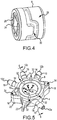
- FIGS. 2, 3 , and 4 A more detailed presentation of the features forming the directional 6 is depicted in FIGS. 2, 3 , and 4 .
- the directional 6 is formed as a wheel-like structure with a smooth engagement sealing surface 28 and a narrow sidewall 29.
- a shaft receptacle 24 is axially centered within the aperture of the directional 6.
- the shaft receptacle 24 may be formed as any regular or irregular shape for the reception of a shaft (not shown) to rotate the directional 6 when mounted within the valve body 4.
- the shaft receptacle 24 in the figures is shaped as a square bore for acceptance of a complementary keyed shaft.
- Shafts for use with the multi-port valve 2 may be motor-driven under a control system or alternately formed with an external lever or handle for turning the directional 6 within the valve body 4 manually.
- the shaft receptacle 24 may be centered axially within the directional 6 and held in place by a number of radial spokes 26 in a web-like structure extending from the exterior walls of the shaft receptacle 24 and attaching to an interior sidewall of the directional 6.
- the shaft receptacle 24 is shown in this embodiment as square, but it may be triangular, hexagonal, octagonal, elliptical, knurled, fluted, or any other keyed shape to interface with shaft receptacle 24 of a complementary shape and rotate the directional 6 within the valve hull 8.
- the shaft receptacle 24 may alternately be circular and sized to create a friction fit with a shaft of otherwise be affixed thereto.
- a fluid channel 30 is formed within a circumferential sealing surface 28 of the directional 6.
- the fluid channel 30 is formed as a recess within the circumferential sidewall 28.
- the fluid channel 30 is a single, continuous channel that is formed across approximately half of the circumference of the directional 6.
- the depth of the fluid channel 30 may extend radially beyond a thickness of the sidewall forming the circumferential sealing surface 28 of the directional 6 such that an outer surface of the fluid channel 30 intersects with the spokes 26.
- a web transverse to the width of the spokes 26 may operate as a wall in the area of the spokes 26 between the front and back face of the directional 6.
- the fluid channel 30 may be understood as composed of two sections: a straight section 42 and a C-shaped section 44.
- the width and depth of the fluid channel 30 may be selected in order to provide adequate and constant fluid flow through the multi-port valve 2 or to satisfy any other functional considerations.
- a longitudinal width of the top and base curves of the C-shaped section 44 of the fluid channel 30 may be twice the transverse width of the fluid channel 30.
- the circumferential sealing surface 28 of the valve hull 8 is wider than the widest part of the fluid channel 30 in order to provide both a bearing surface and a sealing surface for interfacing with the elastomeric seal 10.
- the shape of the fluid channel 30 depicted in the figures is only one possible embodiment for a shape of a fluid channel in the directional. Other configurations are possible in order to accommodate greater or fewer inlet/outlet ports, alternative combinations of fluid communication between ports, or both (see e.g., FIGS. 14 , 19).
- the valve body 4 is shown in greater detail in FIGS. 1 , 5 and 6 .
- four inlet and outlet ports 12a-12d extend outwardly from the outer wall of the valve hull 8.
- the inlet/outlet ports may be referred to as a first port 12a, a second port 12b, a third port 12c, and a fourth port 12d.
- the ports 12a-12d may be arranged in any of a number of configurations. In the implementation shown in FIGS. 1 and 5 , three of the ports 12b-12d extend radially from an outer sidewall of the valve hull 8.
- the first port 12a extends from a sidewall of the valve hull 8 as a projection of a cord that might be drawn between two points on an inner sidewall of the valve hull 8.
- an exemplary port could extend tangentially from the outer sidewall of the valve hull 8 or at any other desirable angle.
- the valve hull 8 may be formed of a substantially rigid polymer, co-polymer, or other plastic.
- Each of the ports 12a-12d may be formed with a straight shaft 14 and form a barb 16 on a distal end in order to assist in the reception and retention of tubing for transporting fluid to and from the multi-port valve 2.
- the elastomeric seal 10 may be formed as an overmolded surface adhered or affixed to the inner sidewall of the valve hull 8. Again, the elastomeric seal 10 forms a seal against the circumferential sealing surface 28 of the directional 6.
- the elastomeric seal 10 may be formed of rubber or any suitable elastomeric polymer material (collectively "elastomeric materials") for forming a seal against an opposing surface.
- the elastomeric seal 10 may be formed, for example, by injection overmolding or compression molding over the inner circumferential surface of the valve hull 8, e.g., as part of a two-step process or by separately molding the elastomeric seal 10 for a press-in fit.
- the material of the elastomeric seal 10 and of the directional 6 are chosen in order to provide a low friction interface to allow for ease of rotation of the directional within the valve body 4 while at the same time providing a fluid tight seal between the two surfaces. While the seal between the elastomeric seal 10 and of the directional 6 may be designed to create a low friction interface, in some implementations lubricant may also be used. In embodiments in which an elastomeric polymer is used, a lubricant like Teflon® can be mixed into the elastomer material to reduce the coefficient of friction.
- Respective lumen 38 are formed within an interior sidewall 36 of the seal 10 in alignment with the lumen 40 of each of the ports 12a-12d to provide fluid coupling between the lumen 40 of the ports 12a-12d and the channel in the directional 6.
- the elastomeric material can also be molded (if overmolded) or fitted (if compression molded) onto the directional 6 such that the same seal effect is achieved between the directional 6 and the valve hull 8.
- the elastomeric seal may be formed as edge seals and the directional may interface directly with the inner wall of the valve hull to place the apertures of the ports in direct fluid communication with the fluid pathway defined in the directional component.
- the elastomeric seal may fit within circumferential recesses formed in the edges if the directional and the valve hull to prevent fluid from leaking therebetween.
- FIGS. 1 , 5 and 6 Additional features of the valve body are shown in FIGS. 1 , 5 and 6 .
- a pair of triangular stacking wings 18 extends from an outer sidewall of the valve hull 8 directly opposite each other. On one side of the stacking wings 18 a recess or hole 34 is formed. On the opposite side of the wings 18, a stacking pin 20 extends above the surface of the stacking wing 18.
- the stacking pins 20 are configured to interface with the stacking holes 34 on the opposite sides of the valve body 4 in order to allow multiple multi-port valves 2 to be stacked on top of each other in alignment for packaging purposes or for control of a number of such multi-port valves 2 with a single shaft inserted within the shaft receptacle 24 of each.
- a key structure 22 is provided for ease in alignment and orientation of the multi-port valve 2 when the valve body 4 is in a housing or other module.
- a number of small channels 32 are formed in the sidewall of the valve body 4 on both sides of the valve body 4 and across both the thickness of the elastomeric seal 10 and the thickness of the wall of the valve hull 8. These channels 32 may be tapered from narrowest to widest radially from an inner edge of the elastomeric seal 10 to an outside edge of the valve hull 8.
- These channels 32 are provided as fluid vents for when the multi-port valves 2 are stacked together in order to direct any fluid that might leak along the interface between the directional 6 and the elastomeric seal 10 radially outward rather than inward toward the shaft receptacle 24 and the spokes 26.
- FIGS. 7A-7G A series of operational positions of a disclosed implementation of the multi-port valve 2 based upon the respective angular orientation of the direction 6 are presented in FIGS. 7A-7G .
- FIG. 7A a first position of the directional 6 within the valve body 4 is shown.
- the valve body 4 is presented in cross-section while the directional 6 is presented in its entirety in order to easily show the alignment between the fluid channel 30 and the directional 6 and the inlet/outlet ports 12a-12d.
- the directional 6 is rotated to provide fluid communication between the fluid channel 30 and the seal apertures 38 for the second port 12b and the third port 12c.
- the fluid apertures 38 leading to the lumens 40 for the first port 12a and the fourth port 12d are not in line with any portion of the fluid channel 30, but instead are positioned adjacent portions of the smooth circumferential sealing surface 28 of the directional, thereby preventing fluid flow into the lumens 40 of the first port 12a and the fourth port 12d.
- FIG. 7B depicts the directional 6 rotated to a second position.
- the seal apertures 38 leading to the second port 12b, the third port 12c, and the fourth port 12d are all in fluid communication with the straight section 42 of the fluid channel 30.
- FIG. 7C depicts the multi-port valve 2 in a third operational position.
- the third port 12c and the fourth port 12d are in fluid communication with the fluid channel 30.
- the first port 12a is again sealed off at the interface between the elastomeric seal 10 and the circumferential sealing surface 28 of the directional 6.
- the second port 12b is also sealed at its corresponding seal aperture 38 against the circumferential sealing surface 28 that forms the interior of the C-shaped section 44 of the fluid channel 30.
- FIG. 7D depicts a fourth position of the directional 6 in the valve body 4 for the multi-port valve 2.
- the second port 12b and the fourth port 12d are in fluid communication with the fluid channel 30 and are thereby in fluid communication with each other.
- the first port 12a is again sealed against the circumferential sealing surface 28 of the directional 6.
- the third port 12c is sealed against the circumferential sealing surface 28 forming the interior of the C-shaped section 44 of the fluid channel 30.
- FIG. 7E depicts a fifth position of the directional 6 within the valve body 4 providing fluid communication between the first port 12a and the third port 12c.
- the seal apertures 38 associated with the lumens 40 of the first port 12a and the third port 12c are positioned adjacent to and in fluid communication with the fluid channel 30.
- the second port 12b is sealed by the circumferential sealing surface 28 of the directional 6 and the fourth port 12d is sealed by the circumferential sealing surface 28 forming the interior of the C-shaped section 44 of the fluid channel 30.
- FIG. 7F A sixth position of the directional 6 within the valve body 4 of the multi-port valve 2 is presented in FIG. 7F .
- the first port 12a and the fourth port 12d are in fluid communication with the fluid lumen 30 and thus with each other.
- the seal aperture 38 corresponding to the lumen 40 of the first port 12a is positioned within the straight section 42 of the fluid channel 30 while the seal aperture 38 of the lumen 40 of the fourth port 12d is positioned at the terminal end of the C-shaped section 44 of the fluid channel 30.
- the second port 12b and the third port 12c are both sealed at the interface of the elastomeric seal 10 and the circumferential surface 28.
- FIG. 7G A seventh position of the directional 6 within the valve body 4 of the multi-port valve 2 is presented in FIG. 7G .
- the first port 12a and the second port 12b are in fluid communication with the fluid lumen 30 and thus with each other.
- the seal aperture 38 corresponding to the lumen 40 of the first port 12a is positioned at the terminal end of the C-shaped section 44 of the fluid channel 30 while the seal aperture 38 of the lumen 40 of the second port 12b is positioned within the straight section 42 of the fluid channel 30.
- the third port 12c and the fourth port 12d are both sealed at the interface of the elastomeric seal 10 and the circumferential surface 28.
- a multi-port valve 2 seven different fluid flow positions variously connecting combinations of two or three of the inlet/outlet ports 12a-12d are possible by rotating the directional 6 within the valve body 4.
- the fluid channel 30 in the directional 6 may be formed in a different pattern to provide for different fluid flow combinations between the inlet and outlet ports 12a-12d.
- FIGS. 8 and 9 illustrate an implementation of a multi-port manifold valve 50 for selectively altering fluid flow between two or more outlet ports and an inlet.
- the multi-port manifold 50 includes a selector or knob 56, a directional 70, a position pin 68 and a valve 57.
- the valve 57 is composed of a hull 52, outlet ports 58a-58g radiating from the hull 52, an inlet port 54 and an elastomeric seal 80.
- the hull 52 is formed as a substantially hollow cylinder and supports the outlet ports 58a-58g and the inlet port 54.
- the hull 52 may also include ribs 84 and an inner wall 82.
- the ribs 84 and the inner wall 82 may be used in implementations where it may be desired to have a lighter-weight multi-port manifold 50, as the amount of material used for the hull 52 may be reduced.
- the hull 52 may be solid to the inner wall 82.
- the hull 52 may be formed of a substantially rigid plastic or the like.
- the outlet ports 58a-58g may include barbs or other retaining devices to allow the outlet ports 58a-58g to receive and retain tubing and/or other conduits.
- the inlet port 54 may include a barb or other retention features on its distal end to allow the inlet port 54 to connect to tubing and/or other conduits. It should be noted that although the inlet port 54 has been designated as an inlet, in some embodiments the outlet ports 58a-58g and the inlet port 54 may function a dual flow ports, similar to the ports 12a-12b in the previous embodiments described above.
- the elastomeric seal 80 is formed as a ring along the inner wall 82 of the hull 52, and is placed within the cavity formed by the hollow cylinder of the hull 52.
- the inner face 78 of the elastomeric seal 80 includes connecting apertures 86 (similar to the seal apertures 38 in FIG. 5 ).
- the connecting apertures 86 are aligned with the outlet ports 58a-58g and the inlet port 54.
- the connecting apertures 86 fluidly connect the inner face 78 and the ports 54, 58a-58g. Similar to the elastomeric seal 10 illustrated in FIG.
- the elastomeric seal 80 may be formed as an overmolded surface adhered to or affixed to the inner wall 82 of the hull 52 and the elastomeric seal 80 may be formed of similar materials and/or processes as the elastomeric seal 10.
- the directional 70 fits within the elastomeric seal 80 and forms a fluid-tight seal with the elastomeric seal 80.
- the directional 70 rotates within the cavity formed within the cylinder of the hull 52.
- the directional 70 has a recessed portion 72, that in combination with the elastomeric seal 80, acts to form a fluid channel within the manifold 50.
- the directional 70 also has a sealing surface 74.
- the sealing surface 74 disconnects the connecting apertures 86 from the fluid channel formed between the elastomeric seal 80 and the recessed portion 72.
- the directional 70 in these embodiments may be altered to have different shapes and/or sizes of the recessed portions 72 and sealing surfaces 74 (e.g., directional 120 illustrated in the embodiment of FIG. 14 ).
- the elastomeric seal may be formed as edge seals and the directional may interface directly with the inner wall of the valve hull to place the apertures of the ports in direct fluid communication with the fluid pathway defined in the directional component.
- the elastomeric seal may fit within circumferential recesses formed in the edges if the directional and the valve hull to prevent fluid from leaking therebetween.
- the knob 56 may be formed to include a cover 60 and a shaft 62 including a tube 64 for securing a position pin 68.
- the knob 56 provides a surface for a user (or machine) to hold in order to rotate the directional 70.
- the shaft 62 may be inserted within a middle aperture of the directional 70 and through a smaller aperture 55 in a base wall 53 of the hull 52 that fits closely to an outer diameter of the shaft 62.
- a retaining ring 76 is placed in an annular recess 63 on a distal end of the shaft 62 that extends below the base wall 53. The retaining ring 76 fits snugly against the base wall 53 to retain the knob 56 against the valve assembly 51 and within the hull 52.
- the shaft 62 and the directional 70 may key together such that as the shaft 62 rotates, the directional 70 rotates.
- the knob 56 includes a position pin 68 operatively connected to a spring 66.
- a position pin 68 operatively connected to a spring 66.
- the position pin 68 moves to a different position along the base wall 53.
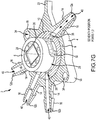
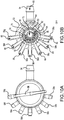
- An inner surface of the base wall 53 has recessed areas 92 (see FIG. 10B ) and as the position pin 68 is moved over the recessed area 92 the spring pushes the position pin 68 into the recessed area 92.
- the user can feel and/or hear the position pin 68 click as it moves to each different position.
- the spring 66 provides a biasing force that has to be overcome in order to alter the position of the knob 56 and, hence, the position of the directional 70.
- the knob 56 (and hence the directional 70) are in a first position.
- this first position all of the outlet ports 58a-58g are fluidly disconnected from the inlet port 54.
- the multi-port manifold 50 is in the off position.
- the lumens 88 or fluid conduits for each of the outlet ports 58a-58g are fluidly sealed from connecting with any fluid flowing from the inlet port 54 via the inlet lumen 90.
- the sealing surface 74 covers the connecting apertures 86 in the elastomeric seal 80. As the sealing surface 74 covers the connecting apertures 86, any fluid flowing within the recessed portion 72 or fluid channel is substantially prevented from accessing the lumens 88 of the outlet ports 58a-58g.
- the directional 70 is in a second position.
- the first port 58a is open and the other ports 58b-58g are closed.
- the sealing surface 74 covers the connecting apertures 86 located in front of the outlet ports 58b-58g, and the recessed portion 72 is located in front of the connecting aperture 86 for the first outlet port 58a, allowing fluid to flow via the recessed portion 72 from the inlet lumen 90 to the outlet lumen 88, fluidly connecting the fluid inlet 54 and the first fluid outlet 58a.
- FIGS. 12A and 12B illustrate a third position for the directional 70.
- all of the outlet ports 58a-58g are fluidly connected to the inlet port 54.
- all of the connecting apertures 86 are uncovered, thus allowing fluid flow from the inlet lumen 90 to the outlet lumens 88, along a fluid channel created by the recessed surface 72.
- the knob 56 and thus the directional 70, may be rotated to any of eight positions (seven open configurations and one closed configuration).
- the first and second ports 58a and 58b are open.
- the first, second and third ports 58a, 58b, and 58c open with the next increment, and so on serially until the third position of FIG. 12B is reached and all seven ports 58a-58g are open.
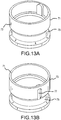
- FIGS. 13A and 13B illustrate a second implementation of the directional that may be used with the multi-port manifold 51 of FIG. 8 .
- the directional 71 includes a recessed portion 75 having a single branch 77 extending vertically towards a top rim of the directional 71.
- the directional 71 may be used to open a single port 58a-58g at a time. For example, as the directional 71 is rotated via the knob 56, the branch 77 may align with only one port 58 at a time, thus the remaining ports 58 are aligned with the sealing surface 73 and are fluidly sealed from connecting with any fluid flowing from the inlet port 54 via the inlet lumen 90.
- the directional 71 In a first position, the directional 71 opens the first fluid port 58a, in a second position the directional 71 seals the first fluid port 58a and opens the second port 58b, and so on serially, such that every port 58a-58g may be selected, but only one of the outlet ports 58a-58g is open at a time.
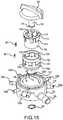
- FIGS. 14 and 15 illustrate a second implementation of the multi-port manifold.
- the directional 120 has differently shaped recessed portions 124 and sealing surfaces 122, also the multi-port manifold 100 has outlet ports 106a-106g spaced intermittently around the hull 102, versus clustered together as with outlet ports 58a-58g illustrated in FIGS. 8-12B .
- a rotator 112 may be used to assist the rotation of the directional 120.
- the rotator 112 is inserted into a middle portion of the directional 120, then a knob 104 including a shaft 110 is inserted within a middle cavity of the rotator 112.
- the shaft 110' defines and annular groove 111 for receipt of the retaining 130 as further described below.
- the rotator 112 is generally cylindrical shaped and has complementary keying surfaces 114, 116 corresponding to aligning surfaces 126, 128 on an inner portion of the directional 120.
- the keying surfaces 114, 116 and the aligning surfaces 126, 128 may be complementary to each other, such that the rotator 112 and the directional 120 may lock together, allowing the rotator 112 to rotate the directional 120 as the rotator 112 rotates.
- the rotator 112 has ribs 118 that provide support for an interior cylindrical wall of smaller diameter that supports the shaft 110.
- the knob 104 may also have key features (not shown) that interface with keyways 119 in the rotator 112. In this implementation, rotating the knob 104 rotates the directional 120.
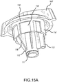
- FIG. 15A depicts an alternate embodiment of the knob 104' with which the rotator 112' structure is integrally formed.
- the rotator 112' is generally cylindrical shaped and has complementary keying surfaces 114', 116' corresponding to aligning surfaces 126, 128 on the inner portion of the directional 120.
- the keying surfaces 114', 116' and the aligning surfaces 126, 128 may be complementary to each other, such that the rotator 112' and the directional 120 may lock together, allowing the rotator 112' to rotate the directional 120 as the knob 104' and rotator 112' rotate.
- the rotator 112' has ribs 118' that provide support for the shaft 110'.
- the shaft 110' defines and annular groove 111' for receipt of the retaining 130 as further described below.
- a sleeve 113' is formed as part of the rotator 112' to house the position pin 68
- the directional 120 is similar to the directionals 6, 70, 71 in the previous implementations, except that the directional 120 includes an annular recess portion 124a extending around a lower portion of the outer wall of the directional 120 and separated recessed cutouts 124b in a sealing surface 122 that are in communication with and extend from the annular recess 124a to a top portion of the directional 120 (i.e. the sealing surface and fluid channels are shaped and sized different from the other directionals). As discussed above, with respect to directionals 6, 70, 71 the shape and size of the recessed portion 124 may be altered to accommodate different port openings based on position and sizes.
- the directional 120 is inserted into the cavity created by the combination of the elastomeric seal 132 and the hull 102.
- the sealing surface 122 of the directional 120 and the elastomeric seal 132 form a fluid-tight seal.
- connecting apertures 140 are fluidly connected with the fluid flow from the inlet 108.
- the shaft 110 may be retained in place within an aperture 105 in a base wall 103 of the hull 102 via a retaining ring 130 that engages the annular groove 111 and interfaces with an outer surface of the base wall 103.
- an inner surface of the base wall 103 may also include recessed surfaces allowing the position pin 68 to click into each position, as discussed above with regard to FIG. 9 .
- the hull 102 may be similar to the hull 52 in the implementation illustrated in FIGS. 8 and 9 .
- the hull 102 includes outlet ports 106a-106g radiating outwards from the outer wall of the hull 102.
- the outlet ports 106a-106g are selectively connected to the inlet port 108 located on the hull 102.
- the hull 102 may include ribs 136 connecting the outer wall to an inner wall 134.
- the elastomeric seal 132 is overmolded on or otherwise attached to the inner wall 134.
- the outlet ports 106a-106g extend through the outer wall of the hull 102 and are aligned with connecting apertures 140 in the elastomeric seal 132.
- FIG. 16 illustrates the directional 120 in a first position.
- outlet ports 106e-106g are fluidly connected with the inlet port 108.
- each of the outlet ports 106a-106g includes a lumen 144 or open conduit for connecting the outlet ports 106a-106g from the outer wall of the hull 102 to the inner wall.
- the directional 120 is aligned such that the recessed surface 124 is aligned with outlet ports 106e-106g, thus fluidly connecting them to the inlet port 108.
- the remaining outlet ports 106a-106d are aligned with the sealing surface 122 and thus are disconnected from the fluid flow.
- FIG. 17 illustrates the directional 120 in a second position.
- the directional 120 is rotated such that every outlet port 106a-106g is fluidly connected to the fluid channel formed by the recessed portion 124.
- the outlet ports 106a-106g are all fluidly connected to the inlet port 108, such that fluid flows from the inlet port 108 to each outlet port 106a-106g.
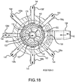
- FIG. 18 illustrates the directional 120 in a third position.
- the directional 120 is rotated such that four outlet ports 106a-106d are open, i.e. fluidly connected with the inlet port 108.
- the remaining outlet ports 106e-106g are disconnected from the recessed portion 124 via the sealing surface 122.
- altering the port locations, connecting apertures and/or the sealing/recessed portions of the directional can alter the combination of ports open/closed with each position.
- more positions and/or combinations of ports may be implemented.
Landscapes
- Engineering & Computer Science (AREA)
- General Engineering & Computer Science (AREA)
- Mechanical Engineering (AREA)
- Multiple-Way Valves (AREA)
Claims (13)
- Verteilerventil mit Mehrfachanschluss (2), umfassend einen Ventilkörper (4), der eine Außenwand (8) aufweist;
einen inneren zylindrischen Hohlraum, der durch die äußere Wand (8) definiert ist; und
mehreren Anschlussöffnungen (12a, 12b, 12c, 12d), die sich von der äußeren Wand (8) erstrecken und jeweilige Leitungen definieren, die sich zwischen Öffnungen in der äußeren Wand (8) und Öffnungen in den distalen Enden der Anschlussöffnungen (12a, 12b, 12c, 12d) erstrecken;
eine Richtungskomponente (6), die in dem Hohlraum positioniert ist, wobei die Richtungskomponente (6) einen Fluidströmungsweg (30) in einer Außenumfangsoberfläche der Richtungskomponente (6) definiert, die selektiv eine Fluidverbindung zwischen Kombinationen aus zwei oder mehreren der Anschlussöffnungen (12a, 12b, 12c, 12d) abhängig von einer Winkelausrichtung der Richtungskomponente (6) innerhalb des Hohlraums bereitstellt; und
eine elastomere Dichtung (10), die zwischen der Richtungskomponente (6) und der äußeren Wand (8) des Ventilkörpers (4) positioniert ist,
wobei das Verteilerventil mit Mehrfachanschluss (2) dadurch gekennzeichnet ist, dass der Fluidströmungsweg (30) ein Kanal (30) in der Außenumfangsoberfläche der Richtungskomponente (6) ist, der aus einem ersten geraden Abschnitt (42) gebildet ist, der mit einem zweiten, C-förmiger Abschnitt (44) verbunden ist. - Verteilerventil mit Mehrfachanschluss (2) nach Anspruch 1, wobei die elastomere Dichtung (10) mehrere Schlitzöffnungen (38) definiert, die jeweils mit den Öffnungen in der äußeren Wand (8) des Ventilkörpers (4) ausgerichtet sind, um eine Fluidverbindung zwischen den Leitungen der mehreren Anschlussöffnungen (12a, 12b, 12c, 12d) und dem Fluidströmungsweg (30) bereitzustellen.
- Verteilerventil mit Mehrfachanschluss (2) nach Anspruch 1, wobei die elastomere Dichtung (10) eine fluiddichte Dichtung zwischen der Richtungskomponente (6) und der äußeren Wand des Ventilkörpers (4) bereitstellt; und/oder
die elastomere Dichtung (10) ein Kautschukmaterial, ein elastisches Material, ein Polymer oder ein elastisches Copolymer umfasst; und/oder
die elastomere Dichtung (10) eine reibungsarme Schnittstelle zwischen der Richtungskomponente (6) und der äußeren Wand (8) des Ventilkörpers (4) bereitstellt; und/oder
die elastomere Dichtung (10) eine aufgeformte Oberfläche auf der inneren Umfangsoberfläche des Ventilkörpers (4) ist; oder
die elastomere Dichtung (10) eine Presspassung, die auf die innere Umfangsoberfläche des Ventilkörpers (4) pressgepasst ist, ist; oder
die elastomere Dichtung (10) eine aufgeformte Oberfläche auf die äußere Umfangsoberfläche der Richtungskomponente (6) ist; oder
die elastomere Dichtung (10) eine Presspassung, die auf die äußere Umfangsoberfläche der Richtungskomponente (6) pressgepasst ist, ist. - Verteilerventil mit Mehrfachanschluss (2) nach Anspruch 1, wobei
eine oder mehrere der mehreren Anschlussöffnungen (12a, 12b, 12c, 12d) von der äußeren Umfangsoberfläche radial nach außen ausgerichtet sind; und/oder
eine oder mehrere der mehreren Anschlussöffnungen (12a, 12b, 12c, 12d) von der Außenumfangsoberfläche als ein Vorsprung eines Seils des ringförmigen Zylinders nach außen ausgerichtet sind; und/oder
eine oder mehrere der mehreren Anschlussöffnungen (12a, 12b, 12c, 12d) tangential von der Außenumfangsoberfläche nach außen ausgerichtet sind; und/oder
Achsen von jedem der Lumen (40) der mehreren Anschlussöffnungen (12a, 12b, 12c, 12d) in einer gemeinsamen Ebene liegen. - Verteilerventil mit Mehrfachanschluss (2) nach Anspruch 1, wobei jede der mehreren Anschlussöffnungen (12a, 12b, 12c, 12d) eine umlaufende Widerhakenstruktur benachbart eines distalen Endes der jeweiligen Anschlussöffnung bildet.
- Verteilerventil mit Mehrfachanschluss (2) nach Anspruch 1, wobei
die mehreren Anschlussöffnungen (12a, 12b, 12c, 12d) eine erste Anschlussöffnung (12a), eine zweite Anschlussöffnung (12b), eine dritte Anschlussöffnung (12c) und eine vierte Anschlussöffnung (12d) in dieser Reihenfolge in Umfangsrichtung um die äußere Umfangsoberfläche des Ventilkörpers (4) herum umfassen;
eine erste Position der Richtungskomponente (6) den Kanal (30) in Fluidverbindung mit der zweiten Anschlussöffnung (12b) und der dritten Anschlussöffnung (12c) platziert;
eine zweite Position der Richtungskomponente (6) den Kanal (30) in Fluidverbindung mit der zweiten Anschlussöffnung (12b), der dritten Anschlussöffnung (12c) und der vierten Anschlussöffnung (12d) platziert;
eine dritte Position der Richtungskomponente (6) den Kanal (30) in Fluidverbindung mit der dritten Anschlussöffnung (12c) und der vierten Anschlussöffnung (12d) platziert;
eine vierte Position der Richtungskomponente (6) den Kanal (30) in Fluidverbindung mit der zweiten Anschlussöffnung (12b) und der vierten Anschlussöffnung (12d) platziert;
eine fünfte Position der Richtungskomponente (6) den Kanal (30) in Fluidverbindung mit der ersten Anschlussöffnung (12a) und der dritten Anschlussöffnung (12c) platziert; und
eine sechste Position der Richtungskomponente (6) den Kanal (30) in Fluidverbindung mit der ersten Anschlussöffnung (12a) und der vierten Anschlussöffnung (12d) platziert; und
eine siebte Position der Richtungskomponente (6) den Kanal (30) in Fluidverbindung mit der ersten Anschlussöffnung (12a) und der zweiten Anschlussöffnung (12b) platziert. - Verteilerventil mit Mehrfachanschluss (2) nach Anspruch 1, wobei der Fluidströmungsweg (30) in der äußeren Umfangsoberfläche der Richtungskomponente (6) durch eine Kombination aus einer Dichtungsfläche (28) ausgebildet ist; und
eine vertiefte Oberfläche (30) in Bezug auf die Dichtungsoberfläche (28) vertieft ist. - Verteilerventil mit Mehrfachanschluss (2) nach Anspruch 7, wobei die vertiefte Oberfläche (30) einen größeren Oberflächenbereich der Richtungskomponente (6) als die Dichtungsoberfläche (28) bedeckt; und/oder
die vertiefte Oberfläche (30) mit Abzweigungen ausgebildet ist, die durch Bereiche der Dichtungsoberfläche (28) definiert sind, welche die Abzweigungen teilweise umgibt. - Verteilerventil mit Mehrfachanschluss (2) nach Anspruch 1 oder 7, wobei mindestens eine der mehreren Anschlussöffnungen (12a, 12b, 12c, 12d) eine Auslassanschlussöffnung ist und mindestens eine der mehreren Anschlussöffnungen (12a, 12b, 12c, 12d) eine Einlassanschlussöffnung ist.
- Verteilerventil mit Mehrfachanschluss (2) nach Anspruch 1 oder 7, wobei
die mehreren Anschlussöffnungen (12a, 12b, 12c, 12d) eine Einlassanschlussöffnung und mehrere Auslassanschlussöffnungen umfassen; und
jede Position der Richtungskomponente (6) die Einlassanschlussöffnung mit einer der Auslassanschlussöffnungen pro Position verbindet; oder
eine Position der Richtungskomponente (6) die Einlassanschlussöffnung fluidisch mit einer Gruppe der Auslassanschlussöffnungen verbindet, die voneinander benachbart sind; oder
nacheinander Positionen der Richtungskomponente (6) benachbarter Auslassanschlussöffnungen in Serie öffnet;
und/oder
eine Position der Richtungskomponente (6) alle der Vielzahl von Auslassanschlussöffnungen schließt. - Verteilerventil mit Mehrfachanschluss (2) nach Anspruch 1 oder 7, ferner umfassend einen Knopf (56), der eine Welle (62) aufweist, wobei die Welle (62) mit der Richtungskomponente (6) derart wirkverbunden ist, dass der Knopf (56) die Richtungskomponente (6) dreht.
- Verteilerventil mit Mehrfachanschluss (2) nach Anspruch 1, ferner umfassend einen Rotator (112), der mit dem Knopf (56) und der Richtungskomponente (6) wirkverbunden ist, so dass das Drehen des Knopfs (56) den Rotator (112) und die Richtungskomponente (6) dreht.
- Verteilerventil mit Mehrfachanschluss (2) nach Anspruch 12, wobei
der Rotator (112) ferner eine erste Schlüsselstruktur und/oder eine zweite Schlüsselstruktur umfasst;
der Knopf (56) ferner eine erste komplementäre Schlüsselstruktur umfasst, die konfiguriert ist, um sich mit der ersten Schlüsselstruktur zu überschneiden; und/oder
die Richtungskomponente (6) ferner eine zweite komplementäre Schlüsselstruktur umfasst, die konfiguriert ist, um sich mit der zweiten Schlüsselstruktur zu überschneiden.
Applications Claiming Priority (2)
| Application Number | Priority Date | Filing Date | Title |
|---|---|---|---|
| US21970509P | 2009-06-23 | 2009-06-23 | |
| US12/818,973 US9371921B2 (en) | 2009-06-23 | 2010-06-18 | Multi-port valve |
Publications (3)
| Publication Number | Publication Date |
|---|---|
| EP2267345A2 EP2267345A2 (de) | 2010-12-29 |
| EP2267345A3 EP2267345A3 (de) | 2014-07-02 |
| EP2267345B1 true EP2267345B1 (de) | 2018-09-26 |
Family
ID=42830597
Family Applications (1)
| Application Number | Title | Priority Date | Filing Date |
|---|---|---|---|
| EP10251136.7A Active EP2267345B1 (de) | 2009-06-23 | 2010-06-23 | Ventil mit mehreren Anschlüssen |
Country Status (3)
| Country | Link |
|---|---|
| US (1) | US9371921B2 (de) |
| EP (1) | EP2267345B1 (de) |
| JP (1) | JP5323767B2 (de) |
Families Citing this family (115)
| Publication number | Priority date | Publication date | Assignee | Title |
|---|---|---|---|---|
| US7448653B2 (en) | 2005-06-10 | 2008-11-11 | Value Plastics, Inc. | Female connector for releasable coupling with a male connector defining a fluid conduit |
| US7806139B2 (en) | 2006-01-20 | 2010-10-05 | Value Plastics, Inc. | Fluid conduit coupling assembly having male and female couplers with integral valves |
| US8085009B2 (en) | 2007-08-13 | 2011-12-27 | The Powerwise Group, Inc. | IGBT/FET-based energy savings device for reducing a predetermined amount of voltage using pulse width modulation |
| US8619443B2 (en) | 2010-09-29 | 2013-12-31 | The Powerwise Group, Inc. | System and method to boost voltage |
| US8698447B2 (en) | 2007-09-14 | 2014-04-15 | The Powerwise Group, Inc. | Energy saving system and method for devices with rotating or reciprocating masses |
| US8810190B2 (en) | 2007-09-14 | 2014-08-19 | The Powerwise Group, Inc. | Motor controller system and method for maximizing energy savings |
| USD654573S1 (en) | 2007-11-19 | 2012-02-21 | Value Plastics, Inc. | Female quick connect fitting |
| US8235426B2 (en) | 2008-07-03 | 2012-08-07 | Nordson Corporation | Latch assembly for joining two conduits |
| USD655393S1 (en) * | 2009-06-23 | 2012-03-06 | Value Plastics, Inc. | Multi-port valve |
| US8698446B2 (en) | 2009-09-08 | 2014-04-15 | The Powerwise Group, Inc. | Method to save energy for devices with rotating or reciprocating masses |
| CA2771121C (en) | 2009-09-08 | 2018-05-15 | The Powerwise Group, Inc. | Energy saving system and method for devices with rotating or reciprocating masses |
| US10711930B2 (en) | 2009-12-09 | 2020-07-14 | Nordson Corporation | Releasable connection assembly |
| US9388929B2 (en) | 2009-12-09 | 2016-07-12 | Nordson Corporation | Male bayonet connector |
| USD650478S1 (en) | 2009-12-23 | 2011-12-13 | Value Plastics, Inc. | Female dual lumen connector |
| USD649240S1 (en) | 2009-12-09 | 2011-11-22 | Value Plastics, Inc. | Male dual lumen bayonet connector |
| USD783815S1 (en) | 2009-12-09 | 2017-04-11 | General Electric Company | Male dual lumen bayonet connector |
| EP2516913B1 (de) | 2009-12-23 | 2014-09-17 | Nordson Corporation | Fluidverbinderverriegelungen mit profildurchführungen |
| CN102753876B (zh) | 2009-12-23 | 2015-07-22 | 诺信公司 | 具有一体式模制悬臂弹簧的按钮闩 |
| DE102010019219B4 (de) | 2010-05-04 | 2013-12-12 | Heraeus Medical Gmbh | Kartuschenverschluss und Kartusche mit einem solchen Verschluss |
| DE102010019224B3 (de) * | 2010-05-04 | 2011-10-13 | Heraeus Medical Gmbh | Austragsvorrichtung für pastöse Massen |
| DE102010019222B4 (de) * | 2010-05-04 | 2013-11-07 | Heraeus Medical Gmbh | Austragsvorrichtung für Kartuschen |
| DE102010019223B4 (de) | 2010-05-04 | 2012-02-16 | Heraeus Medical Gmbh | Kartuschensystem mit Druckgaspatrone |
| DE102010019217B4 (de) | 2010-05-04 | 2014-01-16 | Heraeus Medical Gmbh | Kartuschensystem |
| USD652510S1 (en) | 2011-02-11 | 2012-01-17 | Value Plastics, Inc. | Connector for fluid tubing |
| USD663022S1 (en) | 2011-02-11 | 2012-07-03 | Nordson Corporation | Male body of connector for fluid tubing |
| USD652511S1 (en) | 2011-02-11 | 2012-01-17 | Value Plastics, Inc. | Female body of connector for fluid tubing |
| USD698440S1 (en) | 2011-07-29 | 2014-01-28 | Nordson Corporation | Connector for fluid tubing |
| USD699841S1 (en) | 2011-07-29 | 2014-02-18 | Nordson Corporation | Female body of connector for fluid tubing |
| USD699840S1 (en) | 2011-07-29 | 2014-02-18 | Nordson Corporation | Male body of connector for fluid tubing |
| DE102011108787A1 (de) * | 2011-07-29 | 2013-01-31 | Fresenius Medical Care Deutschland Gmbh | Medizinischer Port, Blutschlauch zur Verwendung bei einer extrakorporalen Blutbehandlung sowie medizinische Behandlungsvorrichtung |
| USD709612S1 (en) | 2011-12-23 | 2014-07-22 | Nordson Corporation | Female dual lumen connector |
| US8770227B2 (en) * | 2012-07-25 | 2014-07-08 | Luciano Hernandez, IV | Flow diverter valve |
| CA2883193C (en) | 2012-08-23 | 2018-05-22 | Djo, Llc | Brace having an inflation control |
| US9481477B2 (en) | 2012-09-17 | 2016-11-01 | Life Technologies Corporation | Fluid manifold system with rotatable port assembly |
| DE102012018596A1 (de) * | 2012-09-20 | 2014-03-20 | Heraeus Medical Gmbh | Drehventilkörper für Austragsvorrichtung für Knochenzemente |
| US9415713B2 (en) | 2013-01-24 | 2016-08-16 | Ford Global Technologies, Llc | Flexible seatback system |
| US9399418B2 (en) | 2013-01-24 | 2016-07-26 | Ford Global Technologies, Llc | Independent cushion extension and thigh support |
| US9409504B2 (en) | 2013-01-24 | 2016-08-09 | Ford Global Technologies, Llc | Flexible seatback system |
| US9968739B2 (en) | 2013-03-14 | 2018-05-15 | Carefusion 303, Inc. | Rotary valve for a disposable infusion set |
| US10226571B2 (en) * | 2013-03-14 | 2019-03-12 | Carefusion 303, Inc. | Pump segment placement |
| DE102013208193A1 (de) * | 2013-05-03 | 2014-11-06 | Behr Thermot-Tronik Gmbh | Elektrisch antreibbares Ventil für eine Regelung von Volumenströmen in einem Heiz- und/oder Kühlsystem eines Kraftfahrzeuges |
| US9505322B2 (en) | 2013-10-25 | 2016-11-29 | Ford Global Technologies, Llc | Manual lumbar pump assembly |
| USD743510S1 (en) * | 2013-10-31 | 2015-11-17 | Nordson Corporation | High pressure fluid conduit connector components and connector assembly |
| US9315131B2 (en) | 2014-01-23 | 2016-04-19 | Ford Global Technologies, Llc | Suspension seat back and cushion system having an inner suspension panel |
| US9752714B2 (en) | 2014-03-28 | 2017-09-05 | Eldon James Corp. | Releasable valved coupler |
| US9421894B2 (en) | 2014-04-02 | 2016-08-23 | Ford Global Technologies, Llc | Vehicle seating assembly with manual independent thigh supports |
| US9789790B2 (en) | 2014-10-03 | 2017-10-17 | Ford Global Technologies, Llc | Tuned flexible support member and flexible suspension features for comfort carriers |
| GB2536042B (en) * | 2015-03-05 | 2022-02-09 | Pluemat Place & Luebeck Gmbh & Co | Multiport for medical device |
| US20160368628A1 (en) | 2015-06-19 | 2016-12-22 | Telebrands Corp. | System, device, and method for filling at least one balloon |
| US10259600B2 (en) | 2015-06-19 | 2019-04-16 | Telebrands Corp. | Container sealing device |
| US9776744B2 (en) | 2015-06-19 | 2017-10-03 | Telebrands Corp. | Container sealing device |
| US10046682B2 (en) | 2015-08-03 | 2018-08-14 | Ford Global Technologies, Llc | Back cushion module for a vehicle seating assembly |
| USD793484S1 (en) * | 2015-11-20 | 2017-08-01 | Telebrands Corp. | Device for filling multiple water balloons |
| USD793485S1 (en) * | 2015-11-20 | 2017-08-01 | Telebrands Corp. | Device for filling multiple water balloons |
| USD793483S1 (en) * | 2015-11-20 | 2017-08-01 | Telebrands Corp. | Device for filling multiple water balloons |
| US10344877B2 (en) * | 2015-12-01 | 2019-07-09 | Tesla Motors, Inc. | Multi-port valve with multiple operation modes |
| EP3405714A4 (de) | 2016-01-19 | 2019-10-16 | WilMarc Holdings, LLC | Verbindersystem zum lösbaren verbinden von fluidleitungen |
| US9849817B2 (en) | 2016-03-16 | 2017-12-26 | Ford Global Technologies, Llc | Composite seat structure |
| US10286818B2 (en) | 2016-03-16 | 2019-05-14 | Ford Global Technologies, Llc | Dual suspension seating assembly |
| US9994135B2 (en) | 2016-03-30 | 2018-06-12 | Ford Global Technologies, Llc | Independent cushion thigh support |
| US10220737B2 (en) | 2016-04-01 | 2019-03-05 | Ford Global Technologies, Llc | Kinematic back panel |
| US9889773B2 (en) | 2016-04-04 | 2018-02-13 | Ford Global Technologies, Llc | Anthropomorphic upper seatback |
| US9802512B1 (en) | 2016-04-12 | 2017-10-31 | Ford Global Technologies, Llc | Torsion spring bushing |
| US9845029B1 (en) | 2016-06-06 | 2017-12-19 | Ford Global Technologies, Llc | Passive conformal seat with hybrid air/liquid cells |
| US9834166B1 (en) | 2016-06-07 | 2017-12-05 | Ford Global Technologies, Llc | Side airbag energy management system |
| US9849856B1 (en) | 2016-06-07 | 2017-12-26 | Ford Global Technologies, Llc | Side airbag energy management system |
| US10166895B2 (en) | 2016-06-09 | 2019-01-01 | Ford Global Technologies, Llc | Seatback comfort carrier |
| US10377279B2 (en) | 2016-06-09 | 2019-08-13 | Ford Global Technologies, Llc | Integrated decking arm support feature |
| DE202016103160U1 (de) * | 2016-06-15 | 2017-09-19 | Woco Industrietechnik Gmbh | Mehrwegeregelventil mit Dichtungsträger |
| US10286824B2 (en) | 2016-08-24 | 2019-05-14 | Ford Global Technologies, Llc | Spreader plate load distribution |
| US10279714B2 (en) | 2016-08-26 | 2019-05-07 | Ford Global Technologies, Llc | Seating assembly with climate control features |
| US10239431B2 (en) | 2016-09-02 | 2019-03-26 | Ford Global Technologies, Llc | Cross-tube attachment hook features for modular assembly and support |
| US10391910B2 (en) | 2016-09-02 | 2019-08-27 | Ford Global Technologies, Llc | Modular assembly cross-tube attachment tab designs and functions |
| US10286825B2 (en) | 2016-09-08 | 2019-05-14 | Ford Global Technologies, Llc | Support assembly for a vehicle seat |
| USD838366S1 (en) | 2016-10-31 | 2019-01-15 | Nordson Corporation | Blood pressure connector |
| US9914378B1 (en) | 2016-12-16 | 2018-03-13 | Ford Global Technologies, Llc | Decorative and functional upper seatback closeout assembly |
| USD862643S1 (en) * | 2017-02-23 | 2019-10-08 | Hill-Rom Services Pte. Ltd. | Flow control apparatus |
| US10350401B2 (en) | 2017-03-08 | 2019-07-16 | Wilmarc Holdings, Llc | Catch assembly for releasably connecting fluid conduits |
| US11655905B2 (en) | 2017-04-07 | 2023-05-23 | Robertshaw Controls Company | Multi-port valve |
| US10596936B2 (en) | 2017-05-04 | 2020-03-24 | Ford Global Technologies, Llc | Self-retaining elastic strap for vent blower attachment to a back carrier |
| DE102017207747A1 (de) * | 2017-05-08 | 2018-11-08 | Kautex Textron Gmbh & Co. Kg | Ventilmodul |
| JP6956536B2 (ja) * | 2017-06-26 | 2021-11-02 | 株式会社デンソー | 三方弁 |
| US11168797B2 (en) * | 2017-08-24 | 2021-11-09 | Vitesco Technologies USA, LLC | Combination multi-port valve |
| DE102018214174A1 (de) * | 2017-08-24 | 2019-02-28 | Continental Automotive Systems, Inc. | Kombinationsventil mit mehreren anschlüssen |
| US10788135B2 (en) * | 2018-02-09 | 2020-09-29 | Nordson Corporation | Multi-port valve |
| KR20200067008A (ko) * | 2018-12-03 | 2020-06-11 | 현대자동차주식회사 | 6웨이 밸브 및 이를 포함한 차량용 열관리시스템 |
| US20220040509A1 (en) * | 2018-12-03 | 2022-02-10 | Avox Systems Inc. | Locking manifold for chemical oxygen generator |
| US11255450B2 (en) | 2018-12-19 | 2022-02-22 | Robertshaw Controls Company | Multi-port multi-plane valve |
| EP3730821B1 (de) * | 2019-04-23 | 2023-07-05 | Vitesco Technologies GmbH | Mehrwegeventil |
| US11719350B2 (en) | 2019-06-12 | 2023-08-08 | Vitesco Technologies USA, LLC | Coolant flow control module |
| US11311458B2 (en) | 2019-09-11 | 2022-04-26 | B Braun Medical Inc. | Binary connector for drug reconstitution |
| US11156300B2 (en) | 2019-10-30 | 2021-10-26 | Robertshaw Controls Company | Multi-port valve with partial circumferential seal arrangement |
| DE102020130488A1 (de) * | 2019-12-16 | 2021-06-17 | ECO Holding 1 GmbH | Vorrichtung zur Handhabung von Fluid innerhalb eines zumindest teilweise elektrisch angetriebenen Fahrzeugs |
| US11773990B2 (en) | 2020-06-05 | 2023-10-03 | Robertshaw Controls Company | Multi-port multi-mode valve |
| KR102842802B1 (ko) * | 2020-09-09 | 2025-08-05 | 현대자동차 주식회사 | 다유로 냉각수 밸브 |
| EP4260058B1 (de) | 2020-12-11 | 2024-11-13 | Life Technologies Corporation | Mehrsäulen-chromatografiesysteme mit drehbaren ventilanordnungen |
| CN115929946A (zh) * | 2020-12-31 | 2023-04-07 | 浙江三花汽车零部件有限公司 | 一种流体控制阀 |
| WO2022152288A1 (zh) * | 2021-01-18 | 2022-07-21 | 浙江三花汽车零部件有限公司 | 控制阀的制造方法、控制阀以及阀体组件 |
| US20220235870A1 (en) * | 2021-01-26 | 2022-07-28 | Dan Knapper | Six Port Valve |
| US12516743B2 (en) | 2021-06-04 | 2026-01-06 | Vitesco Technologies USA, LLC | Multi-port valve assembly |
| US11988290B2 (en) | 2021-11-02 | 2024-05-21 | Vitesco Technologies USA, LLC | Coolant flow control valve |
| WO2023096898A1 (en) * | 2021-11-24 | 2023-06-01 | Silk Road Medical, Inc. | Stopcock with indexing mechanism providing feedback of hub position |
| US11703135B2 (en) | 2021-12-03 | 2023-07-18 | Vitesco Technologies USA, LLC | Multi-port coolant flow control valve assembly |
| DE102021133871A1 (de) * | 2021-12-20 | 2023-06-22 | Vr Automotive Dichtungssysteme Gmbh | Verfahren zur herstellung eines dichtungselements, dichtungselement sowie verwendung eines nach einem solchen verfahren hergestellten dichtungselements |
| CN113975530A (zh) * | 2021-12-22 | 2022-01-28 | 赵祥 | 一种用于同时连接多瓶液体的输液装置 |
| US12158214B2 (en) * | 2022-06-24 | 2024-12-03 | Atieva, Inc. | Rotary refrigerant valve for automotive heat pump control |
| US11846358B1 (en) * | 2022-07-26 | 2023-12-19 | Hanon Systems | Low-profile proportional coolant valve |
| US12359734B2 (en) | 2022-08-25 | 2025-07-15 | Vitesco Technologies USA, LLC | Rotor for multiport coolant flow control valve assembly |
| US20240068576A1 (en) * | 2022-08-30 | 2024-02-29 | Hanon Systems | Fluid valve system |
| CN117847264A (zh) | 2022-10-07 | 2024-04-09 | 斯丹特美国公司 | 多路阀 |
| KR20240085027A (ko) * | 2022-12-07 | 2024-06-14 | 한온시스템 주식회사 | 밸브 조립체 |
| CN221323400U (zh) | 2023-01-10 | 2024-07-12 | 斯丹特美国公司 | 多路阀 |
| EP4704958A1 (de) | 2023-04-25 | 2026-03-11 | WilMarc Holdings, LLC | Geschlechtsloser aseptischer verbinder |
| US12601436B2 (en) | 2023-10-30 | 2026-04-14 | Wilmarc Holdings, Llc | Genderless aseptic connector |
| FR3158551A1 (fr) * | 2024-07-08 | 2025-07-25 | Valeo Systemes Thermiques | Système optimisé de distribution d’un fluide |
Family Cites Families (139)
| Publication number | Priority date | Publication date | Assignee | Title |
|---|---|---|---|---|
| US3073336A (en) * | 1963-01-15 | Lined ball valve | ||
| US909131A (en) * | 1909-01-12 | John J Antic | Hose-coupling. | |
| US185896A (en) * | 1877-01-02 | Improvement in hose-couplings | ||
| US1255847A (en) * | 1917-04-25 | 1918-02-05 | Louis Arkin | Fastener. |
| US1526218A (en) * | 1924-05-12 | 1925-02-10 | Johnson Edward | Pipe coupling |
| USRE21984E (en) * | 1935-09-28 | 1941-12-23 | Fife coupling | |
| US2066473A (en) * | 1936-05-08 | 1937-01-05 | Viber Company Ltd | Conduit for flexible shafts |
| US2147355A (en) * | 1938-06-29 | 1939-02-14 | Albert J Scholtes | Permanent hose coupling |
| US2340119A (en) * | 1942-01-05 | 1944-01-25 | Thompson Prod Inc | Quick disconnect coupling |
| US2701147A (en) * | 1949-02-26 | 1955-02-01 | Aeromat Products Company Inc | Quick-release conduit connection |
| US2626974A (en) * | 1949-09-16 | 1953-01-27 | Pyle National Co | Explosion proof plug and socket |
| FR1061012A (fr) | 1952-07-25 | 1954-04-08 | Perfectionnements aux robinets | |
| NL107546C (de) * | 1956-03-09 | |||
| US2856952A (en) * | 1956-05-04 | 1958-10-21 | Crawford K Stillwagon | Valve |
| US3017203A (en) * | 1957-07-19 | 1962-01-16 | W D Allen Mfg Co | Connectors for plastic hose |
| US2961214A (en) | 1958-12-04 | 1960-11-22 | Duriron Co | Lined valve |
| US3073342A (en) * | 1959-10-05 | 1963-01-15 | Seaton Wilson Mfg Company | Airless coupling |
| US3090396A (en) * | 1960-02-10 | 1963-05-21 | Bruner Corp | Rotatable spindle valve |
| US3078068A (en) * | 1960-07-18 | 1963-02-19 | Russell H Romney | Valved mechanism |
| US3058816A (en) * | 1960-10-26 | 1962-10-16 | Bruner Corp | Brine making and dispensing device |
| US3199835A (en) * | 1961-08-31 | 1965-08-10 | Duriron Co | Sleeve lined plug valves |
| US3166098A (en) * | 1961-12-12 | 1965-01-19 | United Aircraft Corp | Ball valve |
| US3134403A (en) * | 1962-04-02 | 1964-05-26 | Bruner Corp | Rotatable spindle pilot valve |
| US3227380A (en) * | 1963-02-04 | 1966-01-04 | James T Pinkston | Quick connector spigot coupling for spray nozzle and aerator attachments |
| US3560027A (en) * | 1967-02-20 | 1971-02-02 | Gra Tec Inc | Coupling assembly |
| US3481367A (en) | 1967-06-13 | 1969-12-02 | Brunswick Corp | Three-way stopcock |
| US3563265A (en) * | 1967-09-15 | 1971-02-16 | Gra Tec Inc | Ball valve assembly |
| US3575379A (en) | 1969-08-01 | 1971-04-20 | Walworth Co | Encapsulated plug valve |
| US3712583A (en) * | 1971-01-25 | 1973-01-23 | Ametek Inc | Valved for lines carrying extreme temperature fluids |
| US3750704A (en) * | 1971-10-08 | 1973-08-07 | Burron Medical Prod Inc | Multi-way valve |
| US3814129A (en) * | 1972-09-25 | 1974-06-04 | Squibb & Sons Inc | Sampling valve |
| US3825030A (en) | 1973-03-20 | 1974-07-23 | Acf Ind Inc | Lined valves |
| US3957082A (en) | 1974-09-26 | 1976-05-18 | Arbrook, Inc. | Six-way stopcock |
| DE7518809U (de) * | 1975-06-12 | 1978-09-14 | Eppendorf Geraetebau Netheler & Hinz Gmbh, 2000 Hamburg | Pipettenspitze |
| US4172796A (en) * | 1975-09-29 | 1979-10-30 | Teledyne Industries, Inc. | Water purifier apparatus |
| AU513695B2 (en) * | 1976-02-20 | 1980-12-18 | Ihara Chemical Ind Co | Multiport cylindrical valve |
| US4031918A (en) * | 1976-05-24 | 1977-06-28 | Sahlin International, Inc. | Rotary spool valve |
| US4181149A (en) * | 1977-04-07 | 1980-01-01 | Otis Engineering Corporation | Quick disconnect rotary valve coupling |
| US4182519A (en) * | 1978-01-24 | 1980-01-08 | Ralph Wilson | Resilient sealing ring |
| US4288896A (en) | 1978-07-17 | 1981-09-15 | The Dow Chemical Co. | Method for manufacturing an improved plug valve |
| US4207923A (en) | 1978-08-29 | 1980-06-17 | Cobe Laboratories, Inc. | Fluid valve |
| US4366816A (en) * | 1980-12-22 | 1983-01-04 | Abbott Laboratories | Combination quick disconnect coupling and fluid cutoff valve |
| US4434121A (en) * | 1981-10-01 | 1984-02-28 | Audi Nsu Auto Union Aktiengesellschaft | Method for production of a helical spring from a fiber-reinforced plastic |
| US4431218A (en) * | 1982-02-05 | 1984-02-14 | Dayco Corporation | Fluid coupling and method of making same |
| US4431031A (en) * | 1982-03-29 | 1984-02-14 | Amco Corporation | Pre-rinse hose |
| US4494730A (en) * | 1982-11-01 | 1985-01-22 | Xomox Corporation | Plug valve with improved plastic sleeve |
| US4500118A (en) * | 1982-12-30 | 1985-02-19 | Colder Products Company | Fitting apparatus for soft tubing |
| DE3402782A1 (de) * | 1984-01-27 | 1985-08-08 | Unima Maschinenbau Gmbh, 6603 Sulzbach | Absperrorgan mit einem klappenfoermigen abschlussteil |
| US5113904A (en) | 1984-07-13 | 1992-05-19 | Aslanian Jerry L | Flow control device for administration of intravenous fluids |
| US4844413A (en) | 1984-08-20 | 1989-07-04 | The Babcock & Wilcox Company | Shut-off/equalizing valve with molded seals |
| US4635972A (en) * | 1985-05-13 | 1987-01-13 | R. W. Lyall & Company, Inc. | Plastic pipe coupling apparatus and method of using same |
| AU6221686A (en) | 1985-07-23 | 1987-02-10 | Bonardi, Valerio | A fluid stream cock |
| US4645245A (en) * | 1985-10-07 | 1987-02-24 | General Motors Corporation | Quick connect tube coupling |
| JPH0618123Y2 (ja) * | 1989-11-11 | 1994-05-11 | 日東工器株式会社 | 管継手のソケット |
| US4800924A (en) * | 1987-04-24 | 1989-01-31 | Davidson Textron Inc. | Direct drive servovalve with rotary valve |
| JPS646567A (en) * | 1987-06-29 | 1989-01-11 | Toto Ltd | Selector valve |
| USD314050S (en) * | 1987-11-27 | 1991-01-22 | Terumo Kabushiki Kaisha | Medical connector |
| US4896402A (en) * | 1988-02-05 | 1990-01-30 | Band-It-Idex, Inc. | Cable tie |
| USD314233S (en) * | 1988-02-08 | 1991-01-29 | Swagelok Quick-Connect Co. | Quick-connect coupling for a bulkhead |
| FR2640026B2 (fr) * | 1988-06-14 | 1991-03-15 | Hutchinson | Dispositif de raccord rapide et appareillage pour sa mise en oeuvre |
| US4903995A (en) * | 1988-09-30 | 1990-02-27 | Colder Products Company | Self-tightening soft tubing fitting and method of use |
| US4900065A (en) * | 1988-10-31 | 1990-02-13 | Dlh Industries, Inc. | Quick-connect fluid coupling |
| US4904245A (en) * | 1988-12-07 | 1990-02-27 | Allen S. Chen | Surgical valve assembly for urinary bladder irrigation and drainage |
| EP0373272B1 (de) * | 1988-12-16 | 1993-09-08 | John Guest Engineering Limited | Rohrkupplungshülse |
| US4982736A (en) * | 1989-02-08 | 1991-01-08 | Hollister Incorporated | Hermaphroditic coupling for anatomical thermal system |
| US5135026A (en) * | 1989-08-16 | 1992-08-04 | Manska Wayne E | Medical valve having fluid flow indicia |
| US4991880A (en) * | 1989-08-28 | 1991-02-12 | Handy And Harman Automotive Group, Inc. | Quick connect coupling with twist release |
| FR2657940B1 (fr) * | 1990-02-08 | 1992-10-16 | Staubli Sa Ets | Raccord de canalisations du type a clapets tournants. |
| USD332482S (en) * | 1990-03-30 | 1993-01-12 | Elconnex Pty. Limited | Connector for corrugated plastic pipe |
| USD333178S (en) * | 1990-05-31 | 1993-02-09 | Wirthco Engineering, Inc. | Hose coupler |
| US5181752A (en) * | 1990-06-26 | 1993-01-26 | Lokring Corporation | Pipe fitting with swage ring locking mechanism |
| US5105851A (en) * | 1990-10-17 | 1992-04-21 | Hewlett-Packard Company | Apparatus for multi-path flow regulation |
| CA2032830C (en) * | 1990-12-20 | 1994-07-26 | R.S.T. Instruments Ltd. | Coupling |
| US5178303A (en) * | 1991-05-17 | 1993-01-12 | Colder Products Company, Inc. | Dispensing valve apparatus |
| US5188149A (en) * | 1991-06-06 | 1993-02-23 | Williams Richard T | Diverter valve |
| US5316041A (en) * | 1992-10-27 | 1994-05-31 | Colder Product Company | Quick connection coupling valve assembly |
| JPH0643433U (ja) * | 1992-11-17 | 1994-06-10 | 象印マホービン株式会社 | 水路切換弁 |
| JP2585939B2 (ja) * | 1993-01-26 | 1997-02-26 | 大淀小松株式会社 | 破砕装置 |
| DE4324749A1 (de) * | 1993-07-23 | 1995-01-26 | Freudenberg Carl Fa | Regelventil |
| US5385331A (en) * | 1994-03-15 | 1995-01-31 | Aeroquip Corporation | Valve assembly |
| AU4854596A (en) * | 1995-01-06 | 1996-07-24 | Colder Products Company | Low spill high flow quick coupling valve assembly |
| US5601317A (en) * | 1995-02-01 | 1997-02-11 | Signet Systems, Inc. | Clamping system |
| US6382591B1 (en) | 1995-02-16 | 2002-05-07 | Flowserve Management Company | Plug valve assembly |
| US5595217A (en) * | 1995-05-05 | 1997-01-21 | Banjo Corporation | Dry break coupling assembly with cam-locking connection system |
| US6029701A (en) * | 1995-09-19 | 2000-02-29 | Parker Hannifin Sa | Quick-connect coupling for pressurized fluid lines |
| US5709244A (en) * | 1995-10-06 | 1998-01-20 | Condiment Master, Inc. | Collapsible container connector |
| USD388876S (en) * | 1995-12-04 | 1998-01-06 | Sampson Richard K | Barb connector |
| US5848611A (en) | 1996-04-18 | 1998-12-15 | Trw Inc. | Rotary valve |
| FR2749639B1 (fr) * | 1996-06-10 | 1998-08-21 | Hutchinson | Dispositif de raccord rapide pour conduit de fluide sous pression |
| JPH1083842A (ja) * | 1996-09-11 | 1998-03-31 | Meidensha Corp | 亜鉛−臭素電池 |
| DE19637074A1 (de) * | 1996-09-12 | 1998-03-19 | Grohe Kg Hans | Kupplungseinrichtung zur Verbindung zweier Rohrelemente |
| US5855568A (en) * | 1996-11-22 | 1999-01-05 | Liebel-Flarsheim Company | Angiographic syringe and luer connector |
| US6176523B1 (en) * | 1997-03-12 | 2001-01-23 | The Lamson & Sessions Co. | Joint for variable wall thickness conduit |
| USD419861S (en) * | 1997-03-21 | 2000-02-01 | Thomas & Betts Corporation | Single pawl parallel-entry cable tie |
| US5957898A (en) * | 1997-05-20 | 1999-09-28 | Baxter International Inc. | Needleless connector |
| US6019348A (en) * | 1997-09-08 | 2000-02-01 | Dana Corporation | Quick-connection of a fuel fill pipe to a fuel tank |
| EP0916540A3 (de) * | 1997-11-12 | 2000-04-12 | Mannesmann VDO Aktiengesellschaft | Kraftstoffördereinheit mit einem Leitungsanschluss |
| US6196266B1 (en) | 1998-01-16 | 2001-03-06 | Silvano Breda | Multiport diverter valve |
| GB9801261D0 (en) * | 1998-01-21 | 1998-03-18 | Peters Joseph L | Couplings for medical cannulae |
| US5931196A (en) * | 1998-04-29 | 1999-08-03 | United States Filter Corporation | Bypass valve |
| JP2001032985A (ja) * | 1999-07-21 | 2001-02-06 | Tokyo Gas Co Ltd | 配管継手 |
| US6345645B1 (en) * | 1999-12-01 | 2002-02-12 | Caretaker Systems, Inc. | Fluid distribution valve |
| JP3871482B2 (ja) | 1999-12-07 | 2007-01-24 | ナブテスコ株式会社 | 航空機用流体装置 |
| FR2802276B1 (fr) * | 1999-12-13 | 2002-06-07 | Nobel Plastiques | Dispositif de raccordement a basse permeabilite |
| DE10000369A1 (de) * | 2000-01-07 | 2001-07-12 | Bosch Gmbh Robert | Steckverbindungsvorrichtung |
| US6189560B1 (en) * | 2000-01-18 | 2001-02-20 | Vitalaire | Connector assembly for medical gas service outlet |
| CA2400381A1 (en) * | 2000-02-18 | 2001-08-23 | Richard M. Beane | Devices and methods for warming and cleaning lenses of optical surgical instruments |
| US6371444B1 (en) | 2000-06-16 | 2002-04-16 | Mgs Mfg. Group, Inc. | Multi-shot, injection molded valve |
| US6695817B1 (en) * | 2000-07-11 | 2004-02-24 | Icu Medical, Inc. | Medical valve with positive flow characteristics |
| JP4193342B2 (ja) * | 2000-08-11 | 2008-12-10 | コニカミノルタホールディングス株式会社 | 3次元データ生成装置 |
| AU2001296619A1 (en) | 2000-10-06 | 2002-04-15 | Robertshaw Controls Company | Improved stopcock |
| US6688654B2 (en) * | 2000-12-08 | 2004-02-10 | Newfrey Llc | One piece quick connector |
| AU2002235230A1 (en) * | 2000-12-18 | 2002-07-01 | Colder Products Company | Dispensing valve assembly for liquid |
| SE0004701D0 (sv) * | 2000-12-19 | 2000-12-19 | Siemens Elema Ab | Narkosmedelförgasare |
| US6520546B2 (en) * | 2000-12-27 | 2003-02-18 | Itt Manufacturing Enterprises, Inc. | Quick connector release tool |
| GB2373303B (en) * | 2001-01-23 | 2004-07-21 | Smiths Group Plc | A pipe coupling having inner and outer layers of deformable material |
| CA2447666A1 (en) * | 2001-05-21 | 2002-11-28 | Colder Products Company | Connector apparatus and method for connecting the same for controlling fluid dispensing |
| JP2003010112A (ja) * | 2001-06-28 | 2003-01-14 | Olympus Optical Co Ltd | 内視鏡システム |
| USD486909S1 (en) * | 2001-08-27 | 2004-02-17 | Kimberly-Clark Worldwide, Inc. | Bendable connecting device |
| DE10203521A1 (de) * | 2002-01-30 | 2003-07-31 | Modine Mfg Co | Schnellverschlusskupplung |
| US6997919B2 (en) * | 2002-04-23 | 2006-02-14 | Medtronic, Inc. | Implantable medical connector for medical tubing with anchoring features |
| US6874824B2 (en) * | 2002-05-01 | 2005-04-05 | Dahl Brothers Canada Limited | Connection structure having pierced elastomeric gasket |
| ES2245710T3 (es) * | 2002-05-04 | 2006-01-16 | Ti Automotive (Fuldabruck) Gmbh | Acoplamiento de tubo para tuberias. |
| WO2004013525A2 (en) * | 2002-07-31 | 2004-02-12 | Pentapure Incorporated | Tubing attachment |
| FR2844571B1 (fr) | 2002-09-18 | 2008-02-29 | Valeo Thermique Moteur Sa | Vanne de commande pour un circuit de fluide et circuit comportant cette vanne |
| US7316428B2 (en) * | 2002-10-07 | 2008-01-08 | Tokai Rubber Industries, Ltd. | Connection verifying device and connection verifying structure for a pipe and a connector |
| US6981547B2 (en) * | 2002-12-06 | 2006-01-03 | Weatherford/Lamb, Inc. | Wire lock expandable connection |
| FR2849485B1 (fr) * | 2002-12-30 | 2005-09-02 | Valeo Thermique Moteur Sa | Vanne de commande a etancheite amelioree pour circuit de circulation de fluide |
| FR2855589B1 (fr) * | 2003-05-28 | 2006-12-01 | Legris Sa | Dispositif de raccordement instantane |
| US20050033237A1 (en) * | 2003-08-08 | 2005-02-10 | James Fentress | Catheter assemblies and injection molding processes and equipment for making the same |
| US7080665B2 (en) * | 2003-09-09 | 2006-07-25 | Colder Products Company | Connector apparatus and method of coupling bioprocessor equipment to a media source |
| US6945289B2 (en) | 2003-10-24 | 2005-09-20 | The Clorox Company | Bottled water dispenser with shutoff, variable filtration capacity and replaceable cartridge filter |
| US6840277B1 (en) * | 2004-03-12 | 2005-01-11 | Pgi International, Ltd. | Breakaway coupling with flapper valve |
| US7448653B2 (en) * | 2005-06-10 | 2008-11-11 | Value Plastics, Inc. | Female connector for releasable coupling with a male connector defining a fluid conduit |
| US7806139B2 (en) * | 2006-01-20 | 2010-10-05 | Value Plastics, Inc. | Fluid conduit coupling assembly having male and female couplers with integral valves |
| US7887731B2 (en) * | 2006-04-25 | 2011-02-15 | Rexam Closures And Containers Inc. | Method of molding an overmolded beverage closure |
| US7658420B2 (en) * | 2006-07-13 | 2010-02-09 | Parker-Hannifin Corporation | Quick-connect fitting with unlocking ring |
| US8235426B2 (en) * | 2008-07-03 | 2012-08-07 | Nordson Corporation | Latch assembly for joining two conduits |
| USD630320S1 (en) * | 2008-07-03 | 2011-01-04 | Value Plastics, Inc. | Connector for fluid tubing |
-
2010
- 2010-06-18 US US12/818,973 patent/US9371921B2/en active Active
- 2010-06-22 JP JP2010141273A patent/JP5323767B2/ja active Active
- 2010-06-23 EP EP10251136.7A patent/EP2267345B1/de active Active
Non-Patent Citations (1)
| Title |
|---|
| None * |
Also Published As
| Publication number | Publication date |
|---|---|
| US20100319796A1 (en) | 2010-12-23 |
| US9371921B2 (en) | 2016-06-21 |
| EP2267345A3 (de) | 2014-07-02 |
| JP5323767B2 (ja) | 2013-10-23 |
| JP2011007328A (ja) | 2011-01-13 |
| EP2267345A2 (de) | 2010-12-29 |
Similar Documents
| Publication | Publication Date | Title |
|---|---|---|
| EP2267345B1 (de) | Ventil mit mehreren Anschlüssen | |
| US20140053931A1 (en) | Multiple port stopcock valve | |
| JP6511427B2 (ja) | 流路切換弁 | |
| US12366316B2 (en) | Fluid couplings | |
| US9061129B2 (en) | Medical port, blood hose for use in an extracorporeal blood treatment as well as medical treatment appratus | |
| CN111750134B (zh) | 一种阀门及淋浴装置 | |
| AU2017216887B2 (en) | Rotatable valve spool for a manifold | |
| CN102840263A (zh) | 旋转阻尼器 | |
| US12338915B2 (en) | Coolant flow control valve seal assembly | |
| CN217898886U (zh) | 多通阀 | |
| CN210461787U (zh) | 控制阀 | |
| CN206203933U (zh) | 用于形成液体处理设备的头部部分和液体处理设备 | |
| CN221443394U (zh) | 多通阀阀芯和多通阀 | |
| CN219510182U (zh) | 六通阀及温度控制系统 | |
| US12162653B2 (en) | Cap with dual valve aseptic seals | |
| CN110630770B (zh) | 空气调节阀 | |
| CN110960297B (zh) | 一种用于穿刺器的注气组件 | |
| CN210830620U (zh) | 一种便于安装的单向阀 | |
| JP2607062Y2 (ja) | ボールバルブ | |
| US20090159825A1 (en) | Fluid Coupling with a Valve Arrangement | |
| CN114060569B (zh) | 一种阀和龙头 | |
| CN109312872A (zh) | 阀组件及其操作方法 | |
| EP4490064A1 (de) | Kappe mit aseptischen doppelventildichtungen | |
| CN119042439A (zh) | 一种通路可控的三通旋转接头 | |
| CN119222355A (zh) | 阀组件和流体控制装置 |
Legal Events
| Date | Code | Title | Description |
|---|---|---|---|
| PUAI | Public reference made under article 153(3) epc to a published international application that has entered the european phase |
Free format text: ORIGINAL CODE: 0009012 |
|
| 17P | Request for examination filed |
Effective date: 20100723 |
|
| AK | Designated contracting states |
Kind code of ref document: A2 Designated state(s): AL AT BE BG CH CY CZ DE DK EE ES FI FR GB GR HR HU IE IS IT LI LT LU LV MC MK MT NL NO PL PT RO SE SI SK SM TR |
|
| AX | Request for extension of the european patent |
Extension state: BA ME RS |
|
| RAP1 | Party data changed (applicant data changed or rights of an application transferred) |
Owner name: NORDSON CORPORATION |
|
| PUAL | Search report despatched |
Free format text: ORIGINAL CODE: 0009013 |
|
| AK | Designated contracting states |
Kind code of ref document: A3 Designated state(s): AL AT BE BG CH CY CZ DE DK EE ES FI FR GB GR HR HU IE IS IT LI LT LU LV MC MK MT NL NO PL PT RO SE SI SK SM TR |
|
| AX | Request for extension of the european patent |
Extension state: BA ME RS |
|
| RIC1 | Information provided on ipc code assigned before grant |
Ipc: F16K 11/085 20060101AFI20140528BHEP |
|
| RBV | Designated contracting states (corrected) |
Designated state(s): AL AT BE BG CH CY CZ DE DK EE ES FI FR GB GR HR HU IE IS IT LI LT LU LV MC MK MT NL NO PL PT RO SE SI SK SM TR |
|
| GRAP | Despatch of communication of intention to grant a patent |
Free format text: ORIGINAL CODE: EPIDOSNIGR1 |
|
| STAA | Information on the status of an ep patent application or granted ep patent |
Free format text: STATUS: GRANT OF PATENT IS INTENDED |
|
| INTG | Intention to grant announced |
Effective date: 20180426 |
|
| GRAS | Grant fee paid |
Free format text: ORIGINAL CODE: EPIDOSNIGR3 |
|
| GRAA | (expected) grant |
Free format text: ORIGINAL CODE: 0009210 |
|
| STAA | Information on the status of an ep patent application or granted ep patent |
Free format text: STATUS: THE PATENT HAS BEEN GRANTED |
|
| AK | Designated contracting states |
Kind code of ref document: B1 Designated state(s): AL AT BE BG CH CY CZ DE DK EE ES FI FR GB GR HR HU IE IS IT LI LT LU LV MC MK MT NL NO PL PT RO SE SI SK SM TR |
|
| REG | Reference to a national code |
Ref country code: GB Ref legal event code: FG4D |
|
| REG | Reference to a national code |
Ref country code: CH Ref legal event code: EP |
|
| REG | Reference to a national code |
Ref country code: AT Ref legal event code: REF Ref document number: 1046413 Country of ref document: AT Kind code of ref document: T Effective date: 20181015 |
|
| REG | Reference to a national code |
Ref country code: IE Ref legal event code: FG4D |
|
| REG | Reference to a national code |
Ref country code: DE Ref legal event code: R096 Ref document number: 602010053837 Country of ref document: DE |
|
| REG | Reference to a national code |
Ref country code: NL Ref legal event code: MP Effective date: 20180926 |
|
| PG25 | Lapsed in a contracting state [announced via postgrant information from national office to epo] |
Ref country code: BG Free format text: LAPSE BECAUSE OF FAILURE TO SUBMIT A TRANSLATION OF THE DESCRIPTION OR TO PAY THE FEE WITHIN THE PRESCRIBED TIME-LIMIT Effective date: 20181226 Ref country code: LT Free format text: LAPSE BECAUSE OF FAILURE TO SUBMIT A TRANSLATION OF THE DESCRIPTION OR TO PAY THE FEE WITHIN THE PRESCRIBED TIME-LIMIT Effective date: 20180926 Ref country code: NO Free format text: LAPSE BECAUSE OF FAILURE TO SUBMIT A TRANSLATION OF THE DESCRIPTION OR TO PAY THE FEE WITHIN THE PRESCRIBED TIME-LIMIT Effective date: 20181226 Ref country code: SE Free format text: LAPSE BECAUSE OF FAILURE TO SUBMIT A TRANSLATION OF THE DESCRIPTION OR TO PAY THE FEE WITHIN THE PRESCRIBED TIME-LIMIT Effective date: 20180926 Ref country code: FI Free format text: LAPSE BECAUSE OF FAILURE TO SUBMIT A TRANSLATION OF THE DESCRIPTION OR TO PAY THE FEE WITHIN THE PRESCRIBED TIME-LIMIT Effective date: 20180926 Ref country code: GR Free format text: LAPSE BECAUSE OF FAILURE TO SUBMIT A TRANSLATION OF THE DESCRIPTION OR TO PAY THE FEE WITHIN THE PRESCRIBED TIME-LIMIT Effective date: 20181227 |
|
| REG | Reference to a national code |
Ref country code: LT Ref legal event code: MG4D |
|
| PG25 | Lapsed in a contracting state [announced via postgrant information from national office to epo] |
Ref country code: HR Free format text: LAPSE BECAUSE OF FAILURE TO SUBMIT A TRANSLATION OF THE DESCRIPTION OR TO PAY THE FEE WITHIN THE PRESCRIBED TIME-LIMIT Effective date: 20180926 Ref country code: AL Free format text: LAPSE BECAUSE OF FAILURE TO SUBMIT A TRANSLATION OF THE DESCRIPTION OR TO PAY THE FEE WITHIN THE PRESCRIBED TIME-LIMIT Effective date: 20180926 Ref country code: LV Free format text: LAPSE BECAUSE OF FAILURE TO SUBMIT A TRANSLATION OF THE DESCRIPTION OR TO PAY THE FEE WITHIN THE PRESCRIBED TIME-LIMIT Effective date: 20180926 |
|
| REG | Reference to a national code |
Ref country code: AT Ref legal event code: MK05 Ref document number: 1046413 Country of ref document: AT Kind code of ref document: T Effective date: 20180926 |
|
| PG25 | Lapsed in a contracting state [announced via postgrant information from national office to epo] |
Ref country code: CZ Free format text: LAPSE BECAUSE OF FAILURE TO SUBMIT A TRANSLATION OF THE DESCRIPTION OR TO PAY THE FEE WITHIN THE PRESCRIBED TIME-LIMIT Effective date: 20180926 Ref country code: RO Free format text: LAPSE BECAUSE OF FAILURE TO SUBMIT A TRANSLATION OF THE DESCRIPTION OR TO PAY THE FEE WITHIN THE PRESCRIBED TIME-LIMIT Effective date: 20180926 Ref country code: EE Free format text: LAPSE BECAUSE OF FAILURE TO SUBMIT A TRANSLATION OF THE DESCRIPTION OR TO PAY THE FEE WITHIN THE PRESCRIBED TIME-LIMIT Effective date: 20180926 Ref country code: NL Free format text: LAPSE BECAUSE OF FAILURE TO SUBMIT A TRANSLATION OF THE DESCRIPTION OR TO PAY THE FEE WITHIN THE PRESCRIBED TIME-LIMIT Effective date: 20180926 Ref country code: PL Free format text: LAPSE BECAUSE OF FAILURE TO SUBMIT A TRANSLATION OF THE DESCRIPTION OR TO PAY THE FEE WITHIN THE PRESCRIBED TIME-LIMIT Effective date: 20180926 Ref country code: AT Free format text: LAPSE BECAUSE OF FAILURE TO SUBMIT A TRANSLATION OF THE DESCRIPTION OR TO PAY THE FEE WITHIN THE PRESCRIBED TIME-LIMIT Effective date: 20180926 Ref country code: ES Free format text: LAPSE BECAUSE OF FAILURE TO SUBMIT A TRANSLATION OF THE DESCRIPTION OR TO PAY THE FEE WITHIN THE PRESCRIBED TIME-LIMIT Effective date: 20180926 Ref country code: IS Free format text: LAPSE BECAUSE OF FAILURE TO SUBMIT A TRANSLATION OF THE DESCRIPTION OR TO PAY THE FEE WITHIN THE PRESCRIBED TIME-LIMIT Effective date: 20190126 |
|
| PG25 | Lapsed in a contracting state [announced via postgrant information from national office to epo] |
Ref country code: PT Free format text: LAPSE BECAUSE OF FAILURE TO SUBMIT A TRANSLATION OF THE DESCRIPTION OR TO PAY THE FEE WITHIN THE PRESCRIBED TIME-LIMIT Effective date: 20190126 Ref country code: SM Free format text: LAPSE BECAUSE OF FAILURE TO SUBMIT A TRANSLATION OF THE DESCRIPTION OR TO PAY THE FEE WITHIN THE PRESCRIBED TIME-LIMIT Effective date: 20180926 Ref country code: SK Free format text: LAPSE BECAUSE OF FAILURE TO SUBMIT A TRANSLATION OF THE DESCRIPTION OR TO PAY THE FEE WITHIN THE PRESCRIBED TIME-LIMIT Effective date: 20180926 |
|
| REG | Reference to a national code |
Ref country code: DE Ref legal event code: R097 Ref document number: 602010053837 Country of ref document: DE |
|
| PG25 | Lapsed in a contracting state [announced via postgrant information from national office to epo] |
Ref country code: DK Free format text: LAPSE BECAUSE OF FAILURE TO SUBMIT A TRANSLATION OF THE DESCRIPTION OR TO PAY THE FEE WITHIN THE PRESCRIBED TIME-LIMIT Effective date: 20180926 |
|
| PLBE | No opposition filed within time limit |
Free format text: ORIGINAL CODE: 0009261 |
|
| STAA | Information on the status of an ep patent application or granted ep patent |
Free format text: STATUS: NO OPPOSITION FILED WITHIN TIME LIMIT |
|
| 26N | No opposition filed |
Effective date: 20190627 |
|
| PG25 | Lapsed in a contracting state [announced via postgrant information from national office to epo] |
Ref country code: SI Free format text: LAPSE BECAUSE OF FAILURE TO SUBMIT A TRANSLATION OF THE DESCRIPTION OR TO PAY THE FEE WITHIN THE PRESCRIBED TIME-LIMIT Effective date: 20180926 |
|
| PG25 | Lapsed in a contracting state [announced via postgrant information from national office to epo] |
Ref country code: MC Free format text: LAPSE BECAUSE OF FAILURE TO SUBMIT A TRANSLATION OF THE DESCRIPTION OR TO PAY THE FEE WITHIN THE PRESCRIBED TIME-LIMIT Effective date: 20180926 |
|
| REG | Reference to a national code |
Ref country code: CH Ref legal event code: PL |
|
| REG | Reference to a national code |
Ref country code: BE Ref legal event code: MM Effective date: 20190630 |
|
| PG25 | Lapsed in a contracting state [announced via postgrant information from national office to epo] |
Ref country code: TR Free format text: LAPSE BECAUSE OF FAILURE TO SUBMIT A TRANSLATION OF THE DESCRIPTION OR TO PAY THE FEE WITHIN THE PRESCRIBED TIME-LIMIT Effective date: 20180926 |
|
| PG25 | Lapsed in a contracting state [announced via postgrant information from national office to epo] |
Ref country code: IE Free format text: LAPSE BECAUSE OF NON-PAYMENT OF DUE FEES Effective date: 20190623 |
|
| PG25 | Lapsed in a contracting state [announced via postgrant information from national office to epo] |
Ref country code: LI Free format text: LAPSE BECAUSE OF NON-PAYMENT OF DUE FEES Effective date: 20190630 Ref country code: LU Free format text: LAPSE BECAUSE OF NON-PAYMENT OF DUE FEES Effective date: 20190623 Ref country code: CH Free format text: LAPSE BECAUSE OF NON-PAYMENT OF DUE FEES Effective date: 20190630 Ref country code: BE Free format text: LAPSE BECAUSE OF NON-PAYMENT OF DUE FEES Effective date: 20190630 |
|
| PG25 | Lapsed in a contracting state [announced via postgrant information from national office to epo] |
Ref country code: CY Free format text: LAPSE BECAUSE OF FAILURE TO SUBMIT A TRANSLATION OF THE DESCRIPTION OR TO PAY THE FEE WITHIN THE PRESCRIBED TIME-LIMIT Effective date: 20180926 |
|
| PG25 | Lapsed in a contracting state [announced via postgrant information from national office to epo] |
Ref country code: MT Free format text: LAPSE BECAUSE OF FAILURE TO SUBMIT A TRANSLATION OF THE DESCRIPTION OR TO PAY THE FEE WITHIN THE PRESCRIBED TIME-LIMIT Effective date: 20180926 Ref country code: HU Free format text: LAPSE BECAUSE OF FAILURE TO SUBMIT A TRANSLATION OF THE DESCRIPTION OR TO PAY THE FEE WITHIN THE PRESCRIBED TIME-LIMIT; INVALID AB INITIO Effective date: 20100623 |
|
| PG25 | Lapsed in a contracting state [announced via postgrant information from national office to epo] |
Ref country code: MK Free format text: LAPSE BECAUSE OF FAILURE TO SUBMIT A TRANSLATION OF THE DESCRIPTION OR TO PAY THE FEE WITHIN THE PRESCRIBED TIME-LIMIT Effective date: 20180926 |
|
| P01 | Opt-out of the competence of the unified patent court (upc) registered |
Effective date: 20230530 |
|
| PGFP | Annual fee paid to national office [announced via postgrant information from national office to epo] |
Ref country code: DE Payment date: 20250618 Year of fee payment: 16 |
|
| PGFP | Annual fee paid to national office [announced via postgrant information from national office to epo] |
Ref country code: GB Payment date: 20250618 Year of fee payment: 16 |
|
| PGFP | Annual fee paid to national office [announced via postgrant information from national office to epo] |
Ref country code: FR Payment date: 20250624 Year of fee payment: 16 |
|
| PGFP | Annual fee paid to national office [announced via postgrant information from national office to epo] |
Ref country code: IT Payment date: 20250624 Year of fee payment: 16 |