EP2266874A2 - Unterseeboot - Google Patents
Unterseeboot Download PDFInfo
- Publication number
- EP2266874A2 EP2266874A2 EP10005198A EP10005198A EP2266874A2 EP 2266874 A2 EP2266874 A2 EP 2266874A2 EP 10005198 A EP10005198 A EP 10005198A EP 10005198 A EP10005198 A EP 10005198A EP 2266874 A2 EP2266874 A2 EP 2266874A2
- Authority
- EP
- European Patent Office
- Prior art keywords
- periscope
- cleaning
- submarine
- observation window
- pressure
- Prior art date
- Legal status (The legal status is an assumption and is not a legal conclusion. Google has not performed a legal analysis and makes no representation as to the accuracy of the status listed.)
- Granted
Links
Images

Classifications
-
- B—PERFORMING OPERATIONS; TRANSPORTING
- B63—SHIPS OR OTHER WATERBORNE VESSELS; RELATED EQUIPMENT
- B63G—OFFENSIVE OR DEFENSIVE ARRANGEMENTS ON VESSELS; MINE-LAYING; MINE-SWEEPING; SUBMARINES; AIRCRAFT CARRIERS
- B63G8/00—Underwater vessels, e.g. submarines; Equipment specially adapted therefor
- B63G8/38—Arrangement of visual or electronic watch equipment, e.g. of periscopes, of radar
Definitions
- the invention relates to a submarine with the features specified in the preamble of claim 1.
- military submarines are used to reach a mission area in dive travel unnoticed and then also operate unnoticed in this application area.
- these submarines usually have at least one periscope, in which an observation window is arranged on an end section located above the water surface when using the periscope.
- the operational capability of periscopes can be severely impaired, namely, when the impurities in the water settle on the observation window of the periscope and prevent in this way a clear view through the observation window.
- the invention has for its object to provide a submarine that allows unimpaired use of sight pipes even in heavily polluted waters.
- the submarine according to the invention has a pressure body in the usual way.
- this submarine is equipped with at least one periscope, which has an observation window.
- the periscope can be both an optical telescope and an opto-electronically operating periscope, in which inside the periscope in front of the observation window image sensors e.g. are arranged in the form of a CCD or CMOS chip.
- the periscope can be guided and moved by the pressure body of the submarine or, if it is an opto-electronic periscope, it can be mounted completely outside the pressure body, for example in an extension device.
- the submarine according to the invention has a device for cleaning the observation window, so that a clear view through the observation window of the periscope is ensured even in heavily polluted waters.
- the device for cleaning the observation window may, for example, be a windshield wiper system arranged on the side of the tube, as known from vehicle technology.
- a device for cleaning the observation window such a device may be provided which has at least brushing or wiping means which can be brought to bear on the outside of the observation window, wherein by a relative movement between these brushing or wiping means and the observation window a pollution located there can be removed.
- the device for cleaning the observation window on a pressure-cleaning device or is formed by such.
- a device may be provided with which a cleaning agent is preferably sprayed under high pressure on the observation window of the periscope, which can also eliminate otherwise difficult to remove impurities from the outside of the observation window.
- the pressure cleaning device can be designed both for the use of a liquid and for the use of a vaporous cleaning agent, but it is preferred to spray with the pressure cleaning device, a liquid mixture of water and a cleaning agent on the observation window.
- the submarine according to the invention is preferably such a submarine, in which one or more periscopes are arranged in a tower arranged above the pressure hull.
- the pressure cleaning device may conveniently comprise a spray head for spraying the observation window of the periscope located in an upper area of the tower and preferably in an area directly adjacent to the upper tower top.
- the pressure-cleaning device can typically only be used with a spray head located above the water surface.
- the arrangement of the spray head directly below the spire is advantageous causes the submarine to clean the observation window of the periscope must emerge only to the extent that only a small part of the tower protrudes from the water, so that only a very small risk that the submarine is discovered.
- the spray head of the pressure cleaning device may be arranged in a stationary manner in front of the observation window of the periscope, but this expediently requires that the detergent jet emerging from the spray head also covers the entire observation window. If this is not the case and to achieve a particularly good cleaning effect, it is advantageous to form the periscope and the spray head of the pressure-cleaning device relative to each other movable.
- relative movements between the periscope and the spray head may be provided, in which the detergent jet emerging from the spray head moves in the direction of this longitudinal axis and / or transversely over the observation window relative to the longitudinal axis of the periscope and / or in which the angle of incidence of the Detergent jet on the observation window changes.
- the device for cleaning the observation window of the periscope can be arranged completely outside the pressure hull, for example in the tower.
- the device is subjected to a very high compressive stress during dive trips at greater depth, so that a pressure encapsulation or a correspondingly pressure-resistant design must be provided in a complex manner, at least for partial components of the device.
- This proves particularly problematic when the device for cleaning the observation window is a pressure cleaning device.
- the spray head which is preferably arranged in the region of the tower tip, can be conductively connected to a cleaning agent tank arranged in the pressure body.
- This detergent tank is advantageously designed as a pressure vessel, wherein means are provided for pressurizing the cleaner located in the detergent tank.
- the detergent tank for example, be preceded by a pump that promotes the detergent while building a pressure in the detergent tank.
- the detergent tank is conductively connectable to a compressed air supply system of the submarine, so that compressed air can be conducted from the compressed air supply system into the detergent tank, whereby a pressure is exerted on the detergent present in the detergent tank.
- control means may be e.g. Shut-off valves, which are arranged in a supply line from the compressed air supply system of the submarine to the detergent tank and / or in the line connection from the detergent tank to the nozzle head.
- these valves are manually operated or designed controllable.
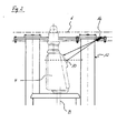
- FIGS. 1 and 2 In a tower of a submarine are an in Fig. 1 Sectionally represented periscope 2 and a in Fig. 2 Sectionally represented periscope 4 is arranged.
- a representation of the tower has been dispensed with, with only one upper end 6 of the tower being indicated by a dashed line.
- the periscope 2 shown is a periscope 2, which serves to observe a possible target of the submarine.
- This in Fig. 2 illustrated periscope 4 is provided for general observation of the space above the water surface at dive trip of a submarine in Sehrohrianae. Both the periscope 2 and the periscope 6 are arranged to be movable in the tower of the submarine in the vertical direction.
- the periscope 2 has an observation window 8.
- This observation window 8 is aligned substantially parallel to a longitudinal axis A of the periscope 2.
- the periscope 6 also has an observation window 10 in an upper end section.
- the observation window 10 of the periscope 4 is oriented obliquely to a longitudinal axis B of the periscope 4.
- a spray head 14 and a spray head 16 are arranged, wherein the spray head 14 in Fig. 1 merely symbolically in the form of an arrow 14 and the spray head 16 in Fig. 2 symbolically represented in the form of an arrow 16.
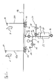
- the spray heads 14 and 16 are both part of an in Fig. 3 illustrated pressure cleaning device, wherein the spray head 14 is provided for cleaning the observation window 8 of the periscope 2 and the spray head 16 for cleaning the observation window 10 of the periscope 4 is used.
- the cleaning of the observation windows 8 and 10 takes place by means of a respective detergent jet emerging from the spray heads 14 and 16, which is directed onto the observation window 8 or onto the observation window 10.
- the spray heads 14 and 16 are each conductively connected to a arranged in the interior of the pressure hull 18 of the submarine cleaner tank 20.
- a leading into the interior of the detergent tank 20 pipe 22 is provided, which extends so far into the detergent tank 20 that it ends in a cleaning liquid located there below a liquid level 24.
- a T-shaped line branch 26 is provided in the pipe 22, from which a wiring harness 22a leads to the spray head 14 and a wiring harness 22b to the spray head 16 through the pressure body 18.
- the line strands 22a and 22b can be closed or opened within the pressure body 18 in each case by means of two shut-off valves 42 and 44 arranged in series.
- the detergent tank 20 has a drain 46.
- the cleaning agent tank 20 is filled with the cleaning liquid via a liquid inlet 28.
- the liquid inlet 28 is line-connected to the pipe 22 leading into the detergent tank 20 via a further T-shaped pipe branch 30 provided in the pipe 22 and a pipe 32 connected thereto.
- the pipe 22 can be closed by means of a shut-off valve 34 arranged between the pipe branches 30 and 26.
- a shut-off valve 36 is arranged, with which the pipe 32 can be opened or closed.
- the cleaning liquid therein is pressurized.
- This pressurization takes place by means of compressed air introduced into the detergent tank 20.
- This compressed air is supplied by an in Fig. 3 not shown compressed air supply system of the submarine via a guided into the detergent tank 20 pipe 37 is provided.
- a shut-off valve 38 and a ball valve 40 are provided on this.
- the shut-off valve 34 Upon reaching a sufficient pressure level in the detergent tank 20, which can be determined by means of a manometer 50 connected to the pipe 32, the shut-off valve 34 is opened, so that the cleaning liquid from the detergent tank 20 in the pipe runs 22a and 22b of the pipe 22 can flow. In the line strands 22a and 22b, the cleaning liquid is initially prevented by the closed shut-off valves 42 and 44 from flowing on to the spray heads 14 and 16.
- shut-off valves 42 and 44 of the respective periscope 2 or 4 associated wiring harness 22a and 22b are opened so that the cleaning liquid to the respective spray head 14 and 16 respectively can continue to flow and there in the form of a cleaning liquid jet, in the FIGS. 1 and 2 each indicated by two of the spray head 14 and 16 outgoing arrows, exits.
- the respective periscope 2 or 4 is extended, wherein the arranged on the periscope 2 and 4 observation window 8 and 10 is guided through the emerging from the spray head 14 and 16 cleaning liquid jet and is cleaned in this way.
- the cleaning process of the observation window 8 or 10 is completed and the shut-off valves 40 and 42 and the shut-off valve 34 can be closed again to allow a further outflow of the cleaning liquid from the detergent tank 20 prevent.
- the check is made by sight through the periscope.
Landscapes
- Engineering & Computer Science (AREA)
- Radar, Positioning & Navigation (AREA)
- Mechanical Engineering (AREA)
- Aviation & Aerospace Engineering (AREA)
- Cleaning By Liquid Or Steam (AREA)
- Cleaning In General (AREA)
- Instruments For Viewing The Inside Of Hollow Bodies (AREA)
Abstract
Description
- Die Erfindung betrifft ein Unterseeboot mit den im Oberbegriff des Anspruchs 1 angegebenen Merkmalen.
- Militärische Unterseeboote werden dazu eingesetzt, ein Einsatzgebiet in Tauchfahrt unbemerkt zu erreichen und dann in diesem Einsatzgebiet ebenfalls unbemerkt zu operieren. Zur Beobachtung des Raums oberhalb der Wasseroberfläche während der Tauchfahrt weisen diese Unterseeboote üblicherweise zumindest ein Sehrohr auf, bei dem an einem bei Einsatz des Sehrohrs oberhalb der Wasseroberfläche befindlichen Endabschnitt ein Beobachtungsfenster angeordnet ist.
- Durch eine starke Wasserverschmutzung und insbesondere durch auf der Wasseroberfläche treibendes Öl kann die Einsatzfähigkeit von Sehrohren stark beeinträchtigt werden, nämlich dann, wenn sich die im Wasser befindlichen Verunreinigungen auf dem Beobachtungsfenster des Sehrohrs absetzen und auf diese Weise einen klaren Durchblick durch das Beobachtungsfenster verhindern.
- Vor diesem Hintergrund liegt der Erfindung die Aufgabe zugrunde, ein Unterseeboot zu schaffen, das auch in stark verunreinigten Gewässern einen unbeeinträchtigten Sehrohreinsatz ermöglicht.
- Gelöst wird diese Aufgabe durch ein Unterseeboot mit den in Anspruch 1 angegebenen Merkmalen. Vorteilhafte Weiterbildungen dieses Unterseeboots ergeben sich aus den Unteransprüchen, der nachfolgenden Beschreibung sowie der Zeichnung. Hierbei können gemäß der Erfindung die Merkmale der Unteransprüche jeweils für sich aber auch in Kombination die erfindungsgemäße Lösung gemäß Anspruch 1 weiter ausgestalten.
- Das erfindungsgemäße Unterseeboot weist in üblicher Weise einen Druckkörper auf. Darüber hinaus ist dieses Unterseeboot mit mindestens einem Sehrohr ausgestattet, das ein Beobachtungsfenster aufweist. Bei dem Sehrohr kann es sich sowohl um ein optisches Teleskop als auch um ein optoelektronisch arbeitendes Sehrohr handeln, bei dem im Inneren des Sehrohrs vor dem Beobachtungsfenster Bildsensoren z.B. in Form eines CCD- oder CMOS-Chips angeordnet sind. Des Weiteren kann das Sehrohr durch den Druckkörper des Unterseeboots geführt und verfahrbar sein oder es kann, falls es sich um ein optoelektronisches Sehrohr handelt, vollständig außerhalb des Druckkörpers beispielsweise in einem Ausfahrgerät gelagert sein.
- Um vor dem Einsatz des Sehrohrs ggf. auf der Außenseite dessen Beobachtungsfensters befindliche Verunreinigungen, wie z.B. Ölschlieren, entfernen zu können, weist das erfindungsgemäße Unterseeboot eine Vorrichtung zum Reinigen des Beobachtungsfensters auf, sodass auch in stark verschmutzten Gewässern eine klare Sicht durch das Beobachtungsfenster des Sehrohrs gewährleistet ist.
- Bei der Vorrichtung zum Reinigen des Beobachtungsfensters kann es sich beispielsweise um eine sehrohrseitig angeordnete Scheibenwischanlage handeln, wie sie aus der Fahrzeugtechnik her bekannt ist. Daneben kann als Vorrichtung zum Reinigen des Beobachtungsfensters auch eine solche Vorrichtung vorgesehen sein, die zumindest Bürsten- oder Wischmittel aufweist, die an der Außenseite des Beobachtungsfensters zur Anlage gebracht werden können, wobei durch eine Relativbewegung zwischen diesen Bürsten- oder Wischmitteln und dem Beobachtungsfenster eine dort befindliche Verschmutzung entfernt werden kann.
- Bevorzugt weist die Vorrichtung zum Reinigen des Beobachtungsfensters eine Druckreinigungsvorrichtung auf oder ist durch eine solche gebildet. Dementsprechend kann eine Vorrichtung vorgesehen sein, mit der ein Reinigungsmittel vorzugsweise unter hohem Druck auf das Beobachtungsfensters des Sehrohrs gesprüht wird, wodurch sich auch ansonsten nur schwer zu entfernende Verunreinigungen von der Außenseite des Beobachtungsfenster beseitigen lassen. Die Druckreinigungsvorrichtung kann sowohl zur Verwendung eines flüssigen als auch zur Verwendung eines dampfförmigen Reinigungsmittels ausgebildet sein, wobei aber bevorzugt wird, mit der Druckreinigungsvorrichtung ein Flüssigkeitsgemisch aus Wasser und einem Reinigungsmittel auf das Beobachtungsfenster zu sprühen.
- Das erfindungsgemäße Unterseeboot ist bevorzugt ein solches Unterseeboot, bei dem ein oder mehrere Sehrohre in einem oberhalb des Druckkörpers angeordneten Turm angeordnet sind. In diesem Fall kann die Druckreinigungsvorrichtung zweckmäßigerweise einen Sprühkopf zum Besprühen des Beobachtungsfensters des Sehrohrs aufweisen, der in einem oberen Bereich des Turms und vorzugsweise in einem direkt an die obere Turmspitze angrenzenden Bereich angeordnet ist. Dies ist insofern vorteilhaft, als die Druckreinigungsvorrichtung typischerweise nur bei einem oberhalb der Wasseroberfläche befindlichen Sprühkopf eingesetzt werden kann. Durch die Anordnung des Sprühkopfs direkt unterhalb der Turmspitze wird vorteilhaft bewirkt, dass das Unterseeboot zum Reinigen des Beobachtungsfensters des Sehrohrs nur soweit auftauchen muss, dass lediglich ein geringer Teil des Turms aus dem Wasser herausragt, sodass nur eine sehr geringe Gefahr besteht, dass das Unterseeboot entdeckt wird.
- In einer Reinigungsstellung kann der Sprühkopf der Druckreinigungsvorrichtung ortsfest vor dem Beobachtungsfenster des Sehrohrs angeordnet sein, dies setzt allerdings sinnvollerweise voraus, dass der aus dem Sprühkopf austretende Reinigungsmittelstrahl auch das gesamte Beobachtungsfenster erfasst. Falls dies nicht der Fall ist und um eine besonders gute Reinigungswirkung zu erzielen, ist es vorteilhaft, das Sehrohr und den Sprühkopf der Druckreinigungsvorrichtung relativ zueinander bewegbar auszubilden. In diesem Zusammenhang können Relativbewegungen zwischen dem Sehrohr und dem Sprühkopf vorgesehen sein, bei denen der aus dem Sprühkopf austretende Reinigungsmittelstrahl bezogen auf die Längsachse des Sehrohrs in Richtung dieser Längsachse und/oder quer dazu über das Beobachtungsfenster wandert und/oder bei denen sich der Auftreffwinkel des Reinigungsmittelstrahls auf dem Beobachtungsfenster ändert. Hierbei ist es grundsätzlich beliebig, ob das Sehrohr, der Düsenkopf oder ob das Sehrohr und der Düsenkopf dementsprechend bewegbar ausgebildet sind.
- Da die in dem Turm eines Unterseeboots angeordneten Sehrohre in der Regel per se aus dem Turm ausfahrbar ausgebildet sind, erweist es sich als konstruktiv günstig, den Sprühkopf der Druckreinigungsvorrichtung, wie es bevorzugt vorgesehen ist, in dem Turm derart ortsfest anzuordnen, dass das Beobachtungsfenster beim Ausfahren des Sehrohres durch den aus dem Sprühkopf austretenden Reinigungsmittelstrahl geführt wird.
- Prinzipiell kann die Vorrichtung zum Reinigen des Beobachtungsfensters des Sehrohres vollständig außerhalb des Druckkörpers, z.B. in dem Turm angeordnet sein. Hierbei ist die Vorrichtung jedoch bei Tauchfahrten in größerer Tiefe einer sehr hohen Druckbeanspruchung ausgesetzt, sodass zumindest für Teilbestandteile der Vorrichtung in aufwendiger Weise eine Druckkapselung oder eine entsprechend druckfeste Ausgestaltung vorzusehen ist. Dies erweist sich insbesondere dann als problematisch, wenn die Vorrichtung zum Reinigen des Beobachtungsfensters eine Druckreinigungsvorrichtung ist. In diesem Fall ist es vorteilhafter, wenn der vorzugsweise im Bereich der Turmspitze angeordnete Sprühkopf mit einem in dem Druckkörper angeordneten Reinigungsmitteltank leitungsverbindbar ist.
- Dieser Reinigungsmitteltank ist vorteilhaft als ein Druckbehälter ausgebildet, wobei Mittel zur Druckbeaufschlagung des in dem Reinigungsmitteltank befindlichen Reinigungsmittels vorgesehen sind. Zum Aufbau des Drucks in dem Reinigungsmitteltank kann dem Reinigungsmitteltank beispielsweise eine Pumpe vorgeschaltet sein, die das Reinigungsmittel unter Aufbau eines Drucks in den Reinigungsmitteltank fördert. Bevorzugt ist der Reinigungsmitteltank aber mit einem Druckluftversorgungssystems des Unterseeboots leitungsverbindbar, sodass Druckluft von dem Druckluftversorgungssystem in den Reinigungsmitteltank geleitet werden kann, wodurch ein Druck auf das in dem Reinigungsmitteltank befindliche Reinigungsmittel ausgeübt wird.
- Zum Betätigen der Vorrichtung zum Reinigen des Beobachtungsfensters des Sehrohrs weist diese vorteilhafterweise entsprechende Steuermittel auf. Bei einer Druckreinigungsvorrichtung können diese Steuermittel z.B. Absperrventile sein, die in einer Zufuhrleitung von dem Druckluftversorgungssystem des Unterseeboots zu dem Reinigungsmitteltank und/oder in der Leitungsverbindung von dem Reinigungsmitteltank zu dem Düsenkopf angeordnet sind. Bevorzugt sind diese Ventile manuell betätigbar order steuerbar ausgebildet.
- Nachfolgend ist die Erfindung anhand eines in den Zeichnungen dargestellten Ausführungsbeispiels näher erläutert. In den Zeichnungen zeigt:
- Fig. 1
- einen in einem Turm eines Unterseeboots angeordneten Abschnitt eines ersten Sehrohrs in schematischer Darstel- lung,
- Fig. 2
- einen in einem Turm eines Unterseeboots angeordneten Abschnitt eines zweiten Sehrohrs in schematischer Darstel- lung und
- Fig. 3
- eine Druckreinigungsvorrichtung in einer stark vereinfach- ten Symboldarstellung.
- In einem Turm eines Unterseeboots sind ein in
Fig. 1 abschnittsweise dargestelltes Sehrohr 2 und ein inFig. 2 abschnittsweise dargestelltes Sehrohr 4 angeordnet. In denFiguren 1 und2 ist der besseren Übersichtlichkeit halber auf eine Darstellung des Turms verzichtet worden, wobei lediglich ein oberes Ende 6 des Turms durch eine gestrichelt gezeichnete Linie angedeutet ist. Bei dem inFig. 1 gezeigten Sehrohr 2 handelt es sich um ein Sehrohr 2, das zur Beobachtung eines möglichen Angriffsziels des Unterseeboots dient. Das inFig. 2 dargestellte Sehrohr 4 ist zur allgemeinen Beobachtung des Raums oberhalb der Wasseroberfläche bei Tauchfahrt eines Unterseeboots in Sehrohrtiefe vorgesehen. Sowohl das Sehrohr 2 als auch das Sehrohr 6 sind in dem Turm des Unterseeboots in vertikaler Richtung verfahrbar angeordnet. - In einem oberen Endabschnitt weist das Sehrohr 2 ein Beobachtungsfenster 8 auf. Dieses Beobachtungsfenster 8 ist im Wesentlichen parallel zu einer Längsachse A des Sehrohrs 2 ausgerichtet. Auch das Sehrohr 6 weist in einem oberen Endabschnitt ein Beobachtungsfenster 10 auf. Im Gegensatz zu dem Beobachtungsfenster 8 des Sehrohrs 2 ist das Beobachtungsfenster 10 des Sehrohrs 4 allerdings schräg zu einer Längsachse B des Sehrohrs 4 ausgerichtet.
- In seinem Inneren weist der Turm des Unterseeboots eine Tragstruktur 12 auf, die lediglich in
Fig. 2 dargestellt ist. An dieser Tragstruktur 12 sind ein Sprühkopf 14 und ein Sprühkopf 16 angeordnet, wobei der Sprühkopf 14 inFig. 1 lediglich symbolisch in Form eines Pfeils 14 und der Sprühkopf 16 inFig. 2 symbolisch in Form eines Pfeils 16 dargestellt sind. Die Sprühköpfe 14 und 16 sind beide Teil einer inFig. 3 dargestellten Druckreinigungsvorrichtung, wobei der Sprühkopf 14 zum Reinigen des Beobachtungsfensters 8 des Sehrohrs 2 vorgesehen ist und der Sprühkopf 16 zum Reinigen des Beobachtungsfensters 10 des Sehrohrs 4 dient. Die Reinigung der Beobachtungsfenster 8 und 10 erfolgt mittels eines jeweils aus den Sprühköpfen 14 und 16 austretenden Reinigungsmittelstrahls, der auf das Beobachtungsfenster 8 bzw. auf das Beobachtungsfenster 10 gerichtet ist. - Die Sprühköpfe 14 und 16 sind jeweils mit einem in dem Inneren des Druckkörpers 18 des Unterseeboots angeordneten Reinigungsmitteltank 20 leitungsverbindbar. Hierzu ist eine in das Innere des Reinigungsmitteltanks 20 führende Rohrleitung 22 vorgesehen, die soweit in den Reinigungsmitteltank 20 reicht, dass sie in einer dort befindlichen Reinigungsflüssigkeit unterhalb eines Flüssigkeitsspiegels 24 endet. Direkt unterhalb einer oberen Wandung des Druckkörpers 18 ist in der Rohrleitung 22 eine T-förmige Leitungsverzweigung 26 vorgesehen, von welcher ein Leitungsstrang 22a zu dem Sprühkopf 14 und ein Leitungsstrang 22b zu dem Sprühkopf 16 durch den Druckkörper 18 führt.
- Die Leitungsstränge 22a und 22b können innerhalb des Druckkörpers 18 jeweils mittels zweier in Reihe angeordneter Absperrventile 42 und 44 verschlossen bzw. geöffnet werden. Um die in dem Reinigungsmitteltank 20 befindliche Reinigungsflüssigkeit ggf. in dem Druckkörper 18 des Unterseeboots ablassen zu können, weist der Reinigungsmitteltank 20 einen Ablass 46 auf.
- Die Befüllung des Reinigungsmitteltanks 20 mit der Reinigungsflüssigkeit erfolgt über einen Flüssigkeitseinlass 28. Hierzu ist der Flüssigkeitseinlass 28 mit der in den Reinigungsmitteltank 20 führenden Rohrleitung 22 über eine weitere in der Rohrleitung 22 vorgesehene T-förmige Leitungsverzweigung 30 und eine daran angeschlossene Rohrleitung 32 leitungsverbunden. Während des Befüllens des Reinigungsmitteltanks 20 über den Flüssigkeitseinlass 28 kann die Rohrleitung 22 mittels eines zwischen den Leitungsverzweigungen 30 und 26 angeordnetes Absperrventil 34 verschlossen werden. Auch an der Rohrleitung 32 ist ein Absperrventil 36 angeordnet, mit dem die Rohrleitung 32 geöffnet oder verschlossen werden kann.
- In dem Reinigungsmitteltank 20 wird die darin befindliche Reinigungsflüssigkeit mit Druck beaufschlagt. Diese Druckbeaufschlagung erfolgt mittels in den Reinigungsmitteltank 20 eingeleiteter Druckluft. Diese Druckluft wird von einem in
Fig. 3 nicht dargestelltem Druckluftversorgungssystem des Unterseeboots über eine in den Reinigungsmitteltank 20 geführte Rohrleitung 37 zur Verfügung gestellt. Zum Verschließen bzw. Öffnen der Rohrleitung 37 sind an dieser ein Absperrventil 38 und ein Kugelventil 40 vorgesehen. - Die Funktionsweise der Druckreinigungsvorrichtung des erfindungsgemäßen Unterseeboots ist wie folgt:
- Zunächst wird der Reinigungsmitteltank 20 mit der Reinigungsflüssigkeit gefüllt. Diese Füllung erfolgt über den Flüssigkeitseinlass 28 bei geöffnet gestelltem Absperrventil 36, während die Rohrleitung 22 zwischen den Leitungsverzweigungen 30 und 26 durch das dort schließend gestellte Absperrventil 34 verschlossen wird. Sobald sich genügend Reinigungsflüssigkeit in dem Reinigungsmitteltank 20 befindet, wird das Absperrventil 36 schließend gestellt, sodass keine weitere Reinigungsflüssigkeit von dem Flüssigkeitseinlass 28 zu dem Reinigungsmitteltank 20 fließen kann.
- Anschließend wird in dem Reinigungsmitteltank 20 ein auf die dort befindliche Reinigungsflüssigkeit wirkender Druck erzeugt. Hierzu werden das Absperrventil 38 und das Kugelventil 40 öffnend gestellt, sodass Druckluft von dem Druckluftversorgungssystem des Unterseeboots über die Rohrleitung 37 in den Reinigungsmitteltank 20 strömen kann.
- Bei Erreichen eines ausreichenden Druckniveaus in dem Reinigungsmitteltank 20, was mittels eines an der Rohrleitung 32 angeschlossenen Manometers 50 festgestellt werden kann, wird das Absperrventil 34 öffnend gestellt, sodass die Reinigungsflüssigkeit von dem Reinigungsmitteltank 20 in die Leitungsstränge 22a und 22b der Rohrleitung 22 strömen kann. In den Leitungssträngen 22a und 22b wird die Reinigungsflüssigkeit zunächst jeweils von den schließend gestellten Absperrventilen 42 und 44 an einem Weiterströmen zu den Sprühköpfen 14 und 16 gehindert.
- Je nachdem welches der Sehrohre 2 oder 4 aus dem Turm des Unterseeboots ausgefahren werden soll, werden die entsprechenden Absperrventile 42 und 44 des dem betreffenden Sehrohr 2 oder 4 zugeordneten Leitungsstrang 22a bzw. 22b geöffnet, sodass die Reinigungsflüssigkeit zu dem betreffenden Sprühkopf 14 bzw. 16 weiterströmen kann und dort in Form eines Reinigungsflüssigkeitsstrahls, der in den
Figuren 1 und2 jeweils von zwei von dem Sprühkopf 14 bzw. 16 ausgehenden Pfeilen angedeutet ist, austritt. - Nun wird das betreffende Sehrohr 2 oder 4 ausgefahren, wobei das an dem Sehrohr 2 bzw. 4 angeordnete Beobachtungsfenster 8 bzw. 10 durch den aus den Sprühkopf 14 bzw. 16 austretenden Reinigungsflüssigkeitsstrahl geführt wird und auf diese Weise gereinigt wird. Sobald sich das Beobachtungsfenster 8 bzw. 10 wieder außerhalb des Reinigungsmittelstrahls befindet, ist der Reinigungsvorgang des Beobachtungsfensters 8 bzw. 10 abgeschlossen und die Absperrventile 40 und 42 sowie das Absperrventil 34 können wieder schließend gestellt werden, um ein weiteres Ausströmen der Reinigungsflüssigkeit aus dem Reinigungsmitteltank 20 zu verhindern. Die Kontrolle erfolgt durch Sicht durch das Sehrohr.
-
- 2
- Sehrohr
- 4
- Sehrohr
- 6
- Ende
- 8
- Beobachtungsfenster
- 10
- Beobachtungsfenster
- 12
- Tragstruktur
- 14
- Sprühkopf, Pfeil
- 16
- Sprühkopf, Pfeil
- 18
- Druckkörper
- 20
- Reinigungsmitteltank
- 22
- Rohrleitung
- 22a, 22b
- Leitungsstrang
- 24
- Flüssigkeitsspiegel
- 26
- Leitungsverzweigung
- 28
- Flüssigkeitseinlass
- 30
- Leitungsverzweigung
- 32
- Rohrleitung
- 34
- Absperrventil
- 36
- Absperrventil
- 37
- Rohrleitung
- 38
- Absperrventil
- 40
- Kugelventil
- 42
- Absperrventil
- 44
- Absperrventil
- 46
- Ablass
- 48
- Manometer
- A
- Längsachse
- B
- Längsachse
Claims (9)
- Unterseeboot mit einem Druckkörper (18) mit zumindest einem Sehrohr (2, 4) mit einem Beobachtungsfenster (8, 10), dadurch gekennzeichnet, dass das Unterseeboot eine Vorrichtung zum Reinigen des Beobachtungsfensters (8, 10) aufweist.
- Unterseeboot nach Anspruch 1, dadurch gekennzeichnet, dass die Vorrichtung zum Reinigen des Beobachtungsfensters eine Druckreinigungsvorrichtung aufweist.
- Unterseeboot nach einem der vorangehenden Ansprüche, dadurch gekennzeichnet, dass die Druckreinigungsvorrichtung einen Sprühkopf (14, 16) aufweist, der in einem oberen Bereich eines Turms des Unterseeboots angeordnet ist.
- Unterseeboot nach einem der vorangehenden Ansprüche, dadurch gekennzeichnet, dass das Sehrohr (2, 4) und der Sprühkopf (14, 16) relativ zueinander bewegbar sind.
- Unterseeboot nach einem der vorangehenden Ansprüche, dadurch gekennzeichnet, dass der Sprühkopf (14, 16) in dem Turm derart ortsfest angeordnet ist, dass das Beobachtungsfenster (8, 10) beim Ausfahren des Sehrohrs (2, 4) durch einen aus dem Sprühkopf (14, 16) austretenden Reinigungsmittelstrahl geführt wird.
- Unterseeboot nach einem der vorangehenden Ansprüche, dadurch gekennzeichnet, dass der Sprühkopf (14, 16) mit einem in dem Druckkörper (18) angeordneten Reinigungsmitteltank (20) leitungsverbindbar ist.
- Unterseeboot nach einem der vorangehenden Ansprüche, dadurch gekennzeichnet, dass der Reinigungsmitteltank (20) als ein Druckbehälter ausgebildet ist und Mittel zur Druckbeaufschlagung des in dem Reinigungsmitteltank (20) befindlichen Reinigungsmittels vorgesehen sind.
- Unterseeboot nach einem der vorangehenden Ansprüche, dadurch gekennzeichnet, dass der Reinigungsmitteltank (20) mit einem Druckluftversorgungssystem des Unterseeboots leitungsverbindbar ist.
- Unterseeboot nach einem der vorangehenden Ansprüche, dadurch gekennzeichnet, dass die Vorrichtung zum Reinigen des Beobachtungsfensters (8, 10) Steuermittel aufweist.
Applications Claiming Priority (1)
| Application Number | Priority Date | Filing Date | Title |
|---|---|---|---|
| DE200910025700 DE102009025700A1 (de) | 2009-06-20 | 2009-06-20 | Unterseeboot |
Publications (3)
| Publication Number | Publication Date |
|---|---|
| EP2266874A2 true EP2266874A2 (de) | 2010-12-29 |
| EP2266874A3 EP2266874A3 (de) | 2013-02-27 |
| EP2266874B1 EP2266874B1 (de) | 2017-01-18 |
Family
ID=42668709
Family Applications (1)
| Application Number | Title | Priority Date | Filing Date |
|---|---|---|---|
| EP10005198.6A Active EP2266874B1 (de) | 2009-06-20 | 2010-05-18 | Unterseeboot |
Country Status (4)
| Country | Link |
|---|---|
| EP (1) | EP2266874B1 (de) |
| KR (1) | KR101304257B1 (de) |
| DE (1) | DE102009025700A1 (de) |
| ES (1) | ES2622118T3 (de) |
Cited By (1)
| Publication number | Priority date | Publication date | Assignee | Title |
|---|---|---|---|---|
| CN112623139A (zh) * | 2020-12-23 | 2021-04-09 | 大连中远海运重工有限公司 | 船舶海底门通用连接器 |
Family Cites Families (6)
| Publication number | Priority date | Publication date | Assignee | Title |
|---|---|---|---|---|
| US1352992A (en) * | 1916-09-14 | 1920-09-14 | Ruggles William Guy | Observation-station |
| GB580493A (en) * | 1944-02-04 | 1946-09-10 | Barr & Stroud Ltd | Improvements in submarine periscopes |
| GB8627560D0 (en) * | 1986-11-18 | 1987-03-18 | Barr & Stroud Ltd | Submarine periscope systems |
| JPH0251168U (de) * | 1988-10-04 | 1990-04-10 | ||
| DE4440150C2 (de) * | 1994-11-10 | 1997-05-15 | Bundesrep Deutschland | Aufklärungsfahrzeug für Uboote |
| DE102005059825A1 (de) * | 2005-12-14 | 2007-02-01 | Carl Zeiss Optronics Gmbh | Mastvorrichtung für ein Unterseeboot |
-
2009
- 2009-06-20 DE DE200910025700 patent/DE102009025700A1/de not_active Withdrawn
-
2010
- 2010-05-18 EP EP10005198.6A patent/EP2266874B1/de active Active
- 2010-05-18 ES ES10005198.6T patent/ES2622118T3/es active Active
- 2010-06-15 KR KR20100056694A patent/KR101304257B1/ko active Active
Non-Patent Citations (1)
| Title |
|---|
| None |
Cited By (1)
| Publication number | Priority date | Publication date | Assignee | Title |
|---|---|---|---|---|
| CN112623139A (zh) * | 2020-12-23 | 2021-04-09 | 大连中远海运重工有限公司 | 船舶海底门通用连接器 |
Also Published As
| Publication number | Publication date |
|---|---|
| KR20120065458A (ko) | 2012-06-21 |
| ES2622118T3 (es) | 2017-07-05 |
| EP2266874B1 (de) | 2017-01-18 |
| KR101304257B1 (ko) | 2013-09-10 |
| EP2266874A3 (de) | 2013-02-27 |
| DE102009025700A1 (de) | 2010-12-30 |
Similar Documents
| Publication | Publication Date | Title |
|---|---|---|
| EP2955069B1 (de) | Kameraeinheit mit einer reinigungsvorrichtung | |
| DE102014116052A1 (de) | Vorrichtung zum Reinigen eines Heckklappenglases für ein Fahrzeug | |
| DE202010001744U1 (de) | Sprühdüseneinheit | |
| DE102014118184A1 (de) | Wischanlage zum Reinigen von Fahrzeugscheiben | |
| EP2687296A2 (de) | Reinigungseinrichtung für die Innenwandreinigung von Behältern | |
| DE20118271U1 (de) | Scheibenwisch-Wasserbehälter | |
| EP2334523B1 (de) | Waschanlage für fahrzeugscheiben sowie rückschlag- und entlüftungsventil für eine solche anlage | |
| EP2266874B1 (de) | Unterseeboot | |
| EP4263298B1 (de) | Reinigungsvorrichtung, reinigungs- und sensorsystem für ein fahrzeug und fahrzeug und verfahren zum reinigen einer zu reinigenden oberfläche eines sensors | |
| DE102011003303A1 (de) | Industrierobotersystem und Verfahren zum Reinigen eines Roboterwerkzeugs | |
| DE102015110912B4 (de) | Reinigungssystem | |
| DE20021641U1 (de) | Reinigungsvorrichtung für Fahrzeuge, vorzugsweise Kraftfahrzeuge | |
| DE3855310T2 (de) | Füllrohr für Erdölprodukte, eingerichtet zu seiner Notentkopplung | |
| DE19908252B4 (de) | Karosseriestruktur | |
| DE885208C (de) | Vorrichtung zum Reinigen der Scheiben, insbesondere der Windschutzscheiben von Fahrzeugen | |
| EP2589530B1 (de) | Ruderpropeller mit einem Ölablasssystem | |
| DE1808757A1 (de) | Verfahren und Vorrichtung zur Reinigung und Desinfektion von Filterelementen und -kesseln innerhalb Scheibenanschwemmfiltern u.dgl. | |
| DE102007011909A1 (de) | Optimierte Systemtechnik zum Impulsreinigen von Motorkomponenten | |
| DE102011115634A1 (de) | Teleskopausleger | |
| DE2045023C3 (de) | Scheibenwascherspritzdüse für Fahrzeuge, insbesondere Kraftfahrzeuge | |
| EP0397132A3 (de) | Vorrichtung zum Entfernen von in den Innenraum von Rohren vorragende Bauteilen oder Materialeinziehungen | |
| EP1190781A2 (de) | Vorrichtung und Verfahren zur emissionsarmen Reinigung eines Tanks | |
| DE3826674A1 (de) | Vorrichtung fuer sichtgeraete in fahrzeugen | |
| DE963651C (de) | Vorrichtung zur Geschwindigkeitsmessung von Schiffen | |
| DE10321582B3 (de) | Vorrichtung zur Verladung von Flüssigkeiten |
Legal Events
| Date | Code | Title | Description |
|---|---|---|---|
| PUAI | Public reference made under article 153(3) epc to a published international application that has entered the european phase |
Free format text: ORIGINAL CODE: 0009012 |
|
| AK | Designated contracting states |
Kind code of ref document: A2 Designated state(s): AL AT BE BG CH CY CZ DE DK EE ES FI FR GB GR HR HU IE IS IT LI LT LU LV MC MK MT NL NO PL PT RO SE SI SK SM TR |
|
| AX | Request for extension of the european patent |
Extension state: BA ME RS |
|
| REG | Reference to a national code |
Ref country code: DE Ref legal event code: R079 Ref document number: 502010013063 Country of ref document: DE Free format text: PREVIOUS MAIN CLASS: B63G0008060000 Ipc: B63G0008380000 |
|
| PUAL | Search report despatched |
Free format text: ORIGINAL CODE: 0009013 |
|
| AK | Designated contracting states |
Kind code of ref document: A3 Designated state(s): AL AT BE BG CH CY CZ DE DK EE ES FI FR GB GR HR HU IE IS IT LI LT LU LV MC MK MT NL NO PL PT RO SE SI SK SM TR |
|
| AX | Request for extension of the european patent |
Extension state: BA ME RS |
|
| RIC1 | Information provided on ipc code assigned before grant |
Ipc: B63G 8/38 20060101AFI20130123BHEP |
|
| RAP1 | Party data changed (applicant data changed or rights of an application transferred) |
Owner name: THYSSENKRUPP MARINE SYSTEMS GMBH |
|
| 17P | Request for examination filed |
Effective date: 20130822 |
|
| RBV | Designated contracting states (corrected) |
Designated state(s): AL AT BE BG CH CY CZ DE DK EE ES FI FR GB GR HR HU IE IS IT LI LT LU LV MC MK MT NL NO PL PT RO SE SI SK SM TR |
|
| GRAP | Despatch of communication of intention to grant a patent |
Free format text: ORIGINAL CODE: EPIDOSNIGR1 |
|
| INTG | Intention to grant announced |
Effective date: 20160810 |
|
| GRAS | Grant fee paid |
Free format text: ORIGINAL CODE: EPIDOSNIGR3 |
|
| GRAA | (expected) grant |
Free format text: ORIGINAL CODE: 0009210 |
|
| AK | Designated contracting states |
Kind code of ref document: B1 Designated state(s): AL AT BE BG CH CY CZ DE DK EE ES FI FR GB GR HR HU IE IS IT LI LT LU LV MC MK MT NL NO PL PT RO SE SI SK SM TR |
|
| REG | Reference to a national code |
Ref country code: GB Ref legal event code: FG4D Free format text: NOT ENGLISH |
|
| REG | Reference to a national code |
Ref country code: CH Ref legal event code: EP |
|
| REG | Reference to a national code |
Ref country code: AT Ref legal event code: REF Ref document number: 862734 Country of ref document: AT Kind code of ref document: T Effective date: 20170215 |
|
| REG | Reference to a national code |
Ref country code: IE Ref legal event code: FG4D Free format text: LANGUAGE OF EP DOCUMENT: GERMAN |
|
| REG | Reference to a national code |
Ref country code: DE Ref legal event code: R096 Ref document number: 502010013063 Country of ref document: DE |
|
| REG | Reference to a national code |
Ref country code: FR Ref legal event code: PLFP Year of fee payment: 8 |
|
| REG | Reference to a national code |
Ref country code: NL Ref legal event code: MP Effective date: 20170118 |
|
| REG | Reference to a national code |
Ref country code: LT Ref legal event code: MG4D |
|
| PG25 | Lapsed in a contracting state [announced via postgrant information from national office to epo] |
Ref country code: NL Free format text: LAPSE BECAUSE OF FAILURE TO SUBMIT A TRANSLATION OF THE DESCRIPTION OR TO PAY THE FEE WITHIN THE PRESCRIBED TIME-LIMIT Effective date: 20170118 |
|
| REG | Reference to a national code |
Ref country code: ES Ref legal event code: FG2A Ref document number: 2622118 Country of ref document: ES Kind code of ref document: T3 Effective date: 20170705 |
|
| PG25 | Lapsed in a contracting state [announced via postgrant information from national office to epo] |
Ref country code: GR Free format text: LAPSE BECAUSE OF FAILURE TO SUBMIT A TRANSLATION OF THE DESCRIPTION OR TO PAY THE FEE WITHIN THE PRESCRIBED TIME-LIMIT Effective date: 20170419 Ref country code: FI Free format text: LAPSE BECAUSE OF FAILURE TO SUBMIT A TRANSLATION OF THE DESCRIPTION OR TO PAY THE FEE WITHIN THE PRESCRIBED TIME-LIMIT Effective date: 20170118 Ref country code: HR Free format text: LAPSE BECAUSE OF FAILURE TO SUBMIT A TRANSLATION OF THE DESCRIPTION OR TO PAY THE FEE WITHIN THE PRESCRIBED TIME-LIMIT Effective date: 20170118 Ref country code: NO Free format text: LAPSE BECAUSE OF FAILURE TO SUBMIT A TRANSLATION OF THE DESCRIPTION OR TO PAY THE FEE WITHIN THE PRESCRIBED TIME-LIMIT Effective date: 20170418 Ref country code: IS Free format text: LAPSE BECAUSE OF FAILURE TO SUBMIT A TRANSLATION OF THE DESCRIPTION OR TO PAY THE FEE WITHIN THE PRESCRIBED TIME-LIMIT Effective date: 20170518 Ref country code: LT Free format text: LAPSE BECAUSE OF FAILURE TO SUBMIT A TRANSLATION OF THE DESCRIPTION OR TO PAY THE FEE WITHIN THE PRESCRIBED TIME-LIMIT Effective date: 20170118 |
|
| REG | Reference to a national code |
Ref country code: DE Ref legal event code: R084 Ref document number: 502010013063 Country of ref document: DE |
|
| PG25 | Lapsed in a contracting state [announced via postgrant information from national office to epo] |
Ref country code: BG Free format text: LAPSE BECAUSE OF FAILURE TO SUBMIT A TRANSLATION OF THE DESCRIPTION OR TO PAY THE FEE WITHIN THE PRESCRIBED TIME-LIMIT Effective date: 20170418 Ref country code: PT Free format text: LAPSE BECAUSE OF FAILURE TO SUBMIT A TRANSLATION OF THE DESCRIPTION OR TO PAY THE FEE WITHIN THE PRESCRIBED TIME-LIMIT Effective date: 20170518 Ref country code: PL Free format text: LAPSE BECAUSE OF FAILURE TO SUBMIT A TRANSLATION OF THE DESCRIPTION OR TO PAY THE FEE WITHIN THE PRESCRIBED TIME-LIMIT Effective date: 20170118 Ref country code: LV Free format text: LAPSE BECAUSE OF FAILURE TO SUBMIT A TRANSLATION OF THE DESCRIPTION OR TO PAY THE FEE WITHIN THE PRESCRIBED TIME-LIMIT Effective date: 20170118 Ref country code: SE Free format text: LAPSE BECAUSE OF FAILURE TO SUBMIT A TRANSLATION OF THE DESCRIPTION OR TO PAY THE FEE WITHIN THE PRESCRIBED TIME-LIMIT Effective date: 20170118 Ref country code: LU Free format text: LAPSE BECAUSE OF NON-PAYMENT OF DUE FEES Effective date: 20170531 |
|
| REG | Reference to a national code |
Ref country code: DE Ref legal event code: R097 Ref document number: 502010013063 Country of ref document: DE |
|
| PG25 | Lapsed in a contracting state [announced via postgrant information from national office to epo] |
Ref country code: RO Free format text: LAPSE BECAUSE OF FAILURE TO SUBMIT A TRANSLATION OF THE DESCRIPTION OR TO PAY THE FEE WITHIN THE PRESCRIBED TIME-LIMIT Effective date: 20170118 Ref country code: SK Free format text: LAPSE BECAUSE OF FAILURE TO SUBMIT A TRANSLATION OF THE DESCRIPTION OR TO PAY THE FEE WITHIN THE PRESCRIBED TIME-LIMIT Effective date: 20170118 Ref country code: CZ Free format text: LAPSE BECAUSE OF FAILURE TO SUBMIT A TRANSLATION OF THE DESCRIPTION OR TO PAY THE FEE WITHIN THE PRESCRIBED TIME-LIMIT Effective date: 20170118 Ref country code: EE Free format text: LAPSE BECAUSE OF FAILURE TO SUBMIT A TRANSLATION OF THE DESCRIPTION OR TO PAY THE FEE WITHIN THE PRESCRIBED TIME-LIMIT Effective date: 20170118 |
|
| PLBE | No opposition filed within time limit |
Free format text: ORIGINAL CODE: 0009261 |
|
| STAA | Information on the status of an ep patent application or granted ep patent |
Free format text: STATUS: NO OPPOSITION FILED WITHIN TIME LIMIT |
|
| PG25 | Lapsed in a contracting state [announced via postgrant information from national office to epo] |
Ref country code: DK Free format text: LAPSE BECAUSE OF FAILURE TO SUBMIT A TRANSLATION OF THE DESCRIPTION OR TO PAY THE FEE WITHIN THE PRESCRIBED TIME-LIMIT Effective date: 20170118 Ref country code: SM Free format text: LAPSE BECAUSE OF FAILURE TO SUBMIT A TRANSLATION OF THE DESCRIPTION OR TO PAY THE FEE WITHIN THE PRESCRIBED TIME-LIMIT Effective date: 20170118 |
|
| 26N | No opposition filed |
Effective date: 20171019 |
|
| REG | Reference to a national code |
Ref country code: CH Ref legal event code: PL |
|
| PG25 | Lapsed in a contracting state [announced via postgrant information from national office to epo] |
Ref country code: MC Free format text: LAPSE BECAUSE OF FAILURE TO SUBMIT A TRANSLATION OF THE DESCRIPTION OR TO PAY THE FEE WITHIN THE PRESCRIBED TIME-LIMIT Effective date: 20170118 |
|
| REG | Reference to a national code |
Ref country code: IE Ref legal event code: MM4A |
|
| PG25 | Lapsed in a contracting state [announced via postgrant information from national office to epo] |
Ref country code: CH Free format text: LAPSE BECAUSE OF NON-PAYMENT OF DUE FEES Effective date: 20170531 Ref country code: LI Free format text: LAPSE BECAUSE OF NON-PAYMENT OF DUE FEES Effective date: 20170531 Ref country code: SI Free format text: LAPSE BECAUSE OF FAILURE TO SUBMIT A TRANSLATION OF THE DESCRIPTION OR TO PAY THE FEE WITHIN THE PRESCRIBED TIME-LIMIT Effective date: 20170118 |
|
| PG25 | Lapsed in a contracting state [announced via postgrant information from national office to epo] |
Ref country code: LU Free format text: LAPSE BECAUSE OF NON-PAYMENT OF DUE FEES Effective date: 20170518 |
|
| REG | Reference to a national code |
Ref country code: BE Ref legal event code: MM Effective date: 20170531 |
|
| PG25 | Lapsed in a contracting state [announced via postgrant information from national office to epo] |
Ref country code: IE Free format text: LAPSE BECAUSE OF NON-PAYMENT OF DUE FEES Effective date: 20170518 |
|
| REG | Reference to a national code |
Ref country code: FR Ref legal event code: PLFP Year of fee payment: 9 |
|
| REG | Reference to a national code |
Ref country code: AT Ref legal event code: MM01 Ref document number: 862734 Country of ref document: AT Kind code of ref document: T Effective date: 20170518 |
|
| PG25 | Lapsed in a contracting state [announced via postgrant information from national office to epo] |
Ref country code: AT Free format text: LAPSE BECAUSE OF NON-PAYMENT OF DUE FEES Effective date: 20170518 Ref country code: BE Free format text: LAPSE BECAUSE OF NON-PAYMENT OF DUE FEES Effective date: 20170531 |
|
| PG25 | Lapsed in a contracting state [announced via postgrant information from national office to epo] |
Ref country code: MT Free format text: LAPSE BECAUSE OF FAILURE TO SUBMIT A TRANSLATION OF THE DESCRIPTION OR TO PAY THE FEE WITHIN THE PRESCRIBED TIME-LIMIT Effective date: 20170118 |
|
| PG25 | Lapsed in a contracting state [announced via postgrant information from national office to epo] |
Ref country code: HU Free format text: LAPSE BECAUSE OF FAILURE TO SUBMIT A TRANSLATION OF THE DESCRIPTION OR TO PAY THE FEE WITHIN THE PRESCRIBED TIME-LIMIT; INVALID AB INITIO Effective date: 20100518 |
|
| REG | Reference to a national code |
Ref country code: DE Ref legal event code: R081 Ref document number: 502010013063 Country of ref document: DE Owner name: THYSSENKRUPP MARINE SYSTEMS GMBH, DE Free format text: FORMER OWNER: THYSSENKRUPP MARINE SYSTEMS GMBH, 24143 KIEL, DE |
|
| PG25 | Lapsed in a contracting state [announced via postgrant information from national office to epo] |
Ref country code: CY Free format text: LAPSE BECAUSE OF NON-PAYMENT OF DUE FEES Effective date: 20170118 |
|
| PG25 | Lapsed in a contracting state [announced via postgrant information from national office to epo] |
Ref country code: MK Free format text: LAPSE BECAUSE OF FAILURE TO SUBMIT A TRANSLATION OF THE DESCRIPTION OR TO PAY THE FEE WITHIN THE PRESCRIBED TIME-LIMIT Effective date: 20170118 |
|
| PG25 | Lapsed in a contracting state [announced via postgrant information from national office to epo] |
Ref country code: TR Free format text: LAPSE BECAUSE OF FAILURE TO SUBMIT A TRANSLATION OF THE DESCRIPTION OR TO PAY THE FEE WITHIN THE PRESCRIBED TIME-LIMIT Effective date: 20170118 |
|
| PG25 | Lapsed in a contracting state [announced via postgrant information from national office to epo] |
Ref country code: AL Free format text: LAPSE BECAUSE OF FAILURE TO SUBMIT A TRANSLATION OF THE DESCRIPTION OR TO PAY THE FEE WITHIN THE PRESCRIBED TIME-LIMIT Effective date: 20170118 |
|
| PGFP | Annual fee paid to national office [announced via postgrant information from national office to epo] |
Ref country code: DE Payment date: 20250521 Year of fee payment: 16 |
|
| PGFP | Annual fee paid to national office [announced via postgrant information from national office to epo] |
Ref country code: GB Payment date: 20250521 Year of fee payment: 16 Ref country code: ES Payment date: 20250627 Year of fee payment: 16 |
|
| PGFP | Annual fee paid to national office [announced via postgrant information from national office to epo] |
Ref country code: IT Payment date: 20250527 Year of fee payment: 16 |
|
| PGFP | Annual fee paid to national office [announced via postgrant information from national office to epo] |
Ref country code: FR Payment date: 20250528 Year of fee payment: 16 |
|
| REG | Reference to a national code |
Ref country code: DE Ref legal event code: R081 Ref document number: 502010013063 Country of ref document: DE Owner name: TKMS GMBH, DE Free format text: FORMER OWNER: THYSSENKRUPP MARINE SYSTEMS GMBH, 24143 KIEL, DE |