EP2266701A1 - Electrode de travail pour une installation de fragmentation électrodynamique - Google Patents
Electrode de travail pour une installation de fragmentation électrodynamique Download PDFInfo
- Publication number
- EP2266701A1 EP2266701A1 EP10009321A EP10009321A EP2266701A1 EP 2266701 A1 EP2266701 A1 EP 2266701A1 EP 10009321 A EP10009321 A EP 10009321A EP 10009321 A EP10009321 A EP 10009321A EP 2266701 A1 EP2266701 A1 EP 2266701A1
- Authority
- EP
- European Patent Office
- Prior art keywords
- expansion sleeve
- expansion
- working electrode
- central conductor
- working
- Prior art date
- Legal status (The legal status is an assumption and is not a legal conclusion. Google has not performed a legal analysis and makes no representation as to the accuracy of the status listed.)
- Granted
Links
- 238000013467 fragmentation Methods 0.000 title claims description 10
- 238000006062 fragmentation reaction Methods 0.000 title claims description 10
- 230000005520 electrodynamics Effects 0.000 title claims description 9
- 239000004020 conductor Substances 0.000 claims abstract description 50
- 239000012212 insulator Substances 0.000 claims abstract description 21
- 230000007480 spreading Effects 0.000 claims description 20
- 230000008859 change Effects 0.000 claims description 14
- 238000006073 displacement reaction Methods 0.000 claims description 14
- 239000011324 bead Substances 0.000 claims description 11
- 230000000694 effects Effects 0.000 claims description 3
- 238000000034 method Methods 0.000 claims description 3
- 230000008569 process Effects 0.000 claims description 3
- 238000013461 design Methods 0.000 claims description 2
- 239000012530 fluid Substances 0.000 claims description 2
- 230000035515 penetration Effects 0.000 claims description 2
- 239000002893 slag Substances 0.000 claims description 2
- 239000000463 material Substances 0.000 description 7
- 238000010276 construction Methods 0.000 description 5
- 230000015556 catabolic process Effects 0.000 description 4
- 230000008901 benefit Effects 0.000 description 3
- 230000015572 biosynthetic process Effects 0.000 description 3
- 238000011109 contamination Methods 0.000 description 2
- 230000006378 damage Effects 0.000 description 2
- 230000002093 peripheral effect Effects 0.000 description 2
- 230000010349 pulsation Effects 0.000 description 2
- 238000005476 soldering Methods 0.000 description 2
- 229910001220 stainless steel Inorganic materials 0.000 description 2
- 239000010935 stainless steel Substances 0.000 description 2
- 238000003466 welding Methods 0.000 description 2
- RYGMFSIKBFXOCR-UHFFFAOYSA-N Copper Chemical compound [Cu] RYGMFSIKBFXOCR-UHFFFAOYSA-N 0.000 description 1
- XAGFODPZIPBFFR-UHFFFAOYSA-N aluminium Chemical compound [Al] XAGFODPZIPBFFR-UHFFFAOYSA-N 0.000 description 1
- 229910052782 aluminium Inorganic materials 0.000 description 1
- 230000005540 biological transmission Effects 0.000 description 1
- 229910010293 ceramic material Inorganic materials 0.000 description 1
- 239000007795 chemical reaction product Substances 0.000 description 1
- 229910052802 copper Inorganic materials 0.000 description 1
- 239000010949 copper Substances 0.000 description 1
- 230000008878 coupling Effects 0.000 description 1
- 238000010168 coupling process Methods 0.000 description 1
- 238000005859 coupling reaction Methods 0.000 description 1
- 230000001419 dependent effect Effects 0.000 description 1
- 238000004090 dissolution Methods 0.000 description 1
- 239000007772 electrode material Substances 0.000 description 1
- 238000003780 insertion Methods 0.000 description 1
- 230000037431 insertion Effects 0.000 description 1
- 238000009434 installation Methods 0.000 description 1
- 239000007788 liquid Substances 0.000 description 1
- 238000012423 maintenance Methods 0.000 description 1
- 239000007769 metal material Substances 0.000 description 1
- 230000007935 neutral effect Effects 0.000 description 1
- 238000012549 training Methods 0.000 description 1
- XLYOFNOQVPJJNP-UHFFFAOYSA-N water Substances O XLYOFNOQVPJJNP-UHFFFAOYSA-N 0.000 description 1
Images


Classifications
-
- B—PERFORMING OPERATIONS; TRANSPORTING
- B02—CRUSHING, PULVERISING, OR DISINTEGRATING; PREPARATORY TREATMENT OF GRAIN FOR MILLING
- B02C—CRUSHING, PULVERISING, OR DISINTEGRATING IN GENERAL; MILLING GRAIN
- B02C19/00—Other disintegrating devices or methods
- B02C19/18—Use of auxiliary physical effects, e.g. ultrasonics, irradiation, for disintegrating
- B02C2019/183—Crushing by discharge of high electrical energy
Definitions
- the invention relates to a working electrode for an electrodynamic fragmentation system, change parts for such a working electrode and a use of the working electrode according to the preambles of the independent claims.
- high voltage breakdowns are produced by a working electrode applied to high voltage pulses and a base electrode, which is usually at a neutral potential, through the material to be comminuted, which leads to the comminution of the material.
- a slight removal of material at the working electrode tip takes place at each high-voltage breakdown, so that it is worn after a certain period of use and must be replaced. It may also be necessary to change the electrode when changing the material to be digested with the equipment in order to prevent contamination of the end product with unwanted electrode material.
- high-voltage electrodes are known from the prior art in which the electrode tip is formed by an exchangeable exchangeable part and which thereby largely avoid the aforementioned disadvantages.
- Such high voltage electrodes are for example in SU 1790069 A1 . SU 1781892 A1 . JP 2003 001137 A . US 2005/0150668 A1 . DE 38 44 419 A1 and US 4,458,153 shown.
- the electrode tip is either screwed to the central conductor of the high voltage electrode or in the case of DE 38 44 419 A1
- these high-voltage electrodes have the disadvantage that it can come at high pressure pulsations in the working space to a dissolution of the electrode tip forming change part and in the case of the clamped electrode tip also a structurally relatively complex arrangement for fixing the Electrode tip is required.
- a first aspect of the invention relates to a working electrode for an electrodynamic fragmentation system with a replaceable electrode tip.
- the working electrode comprises an insulator body, for example made of plastic or of a ceramic material, with a central conductor of a highly electrically conductive, preferably metallic material, for example of aluminum, copper or stainless steel, which passes through the insulator axially.
- a high voltage generator for charging the working electrode with high voltage pulses.
- the central conductor At its other end, the so-called working end, which dips in operation in the filled with process fluid, eg water, and the material to be crushed workspace of the fragmentation, the central conductor carries an electrode tip, which forms the starting point for the voltage breakdown in operation.
- the electrode tip is formed by a replaceable, one-piece or multi-part removable part.
- the removable part is frictionally secured by clamping in an end opening in the working end of the central conductor, which is preferably accomplished by the replacement part comprises a preferably cylindrical expansion sleeve and an at least partially arranged in the expansion sleeve expansion means by which the expansion sleeve in such a spreadable area is that it is pressed radially against the wall of the frontal opening and thereby clamped axially immovable in the opening.
- such working electrodes have the advantage that when a wear of the electrode or a change in the material to be crushed, only the electrode tip must be changed and, for example, an opening of an oil-filled high-voltage system for the purpose of replacing the entire working electrode is superfluous. It is thereby advantageous to significantly reduce the maintenance-related downtime and operating costs of electrodynamic fragmentation systems. It is advantageous if the expansion body is connected to a drive element for axially displacing it with respect to the expansion sleeve to effect a radial spreading of the expansion sleeve, which protrudes at the working end of the central conductor emerges from the frontal opening and at its end facing away from the spreader end forms the electrode tip.
- the clamping of the removable part in the central conductor can be effected in a simple manner by exerting an axial force on the drive element. If, in addition, the expansion body and the drive element are formed integrally with one another, which is preferred, the result is a particularly simple and robust construction.
- the expansion body has a preferably cone-shaped or pyramid-shaped section for radial spreading of the expansion sleeve or is formed overall as a cone or truncated pyramid, as this very large expansion forces can be generated in a controlled manner.
- the drive element wipe the electrode tip and the spreader on an external thread, by means of which an axial force can be exerted on this to effect a displacement of the spreader and a resulting radial expansion and clamping of the expansion in the opening in the central conductor.
- an axial force can be exerted on this to effect a displacement of the spreader and a resulting radial expansion and clamping of the expansion in the opening in the central conductor.
- the expansion body is designed such that an axial displacement of the same towards the working end of the central conductor causes a radial spreading of the expansion sleeve, the drive element for clamping the change part in the central conductor so tensile forces must be transmitted, it is advantageous if the external thread the drive element for generating the axial displacement forces cooperates with a corresponding internal thread of an abutment element, which is supported axially on the expansion sleeve. This results in a simple construction with few components.
- the abutment element is designed as a hexagon nut or as a face nut with at least two end holes, which preferably have a circumferential, on its outer circumference, has radial bead, which can serve as field relief.
- the expansion body is designed such that an axial displacement of the same in the direction away from the working end of the central conductor causes a radial spreading of the expansion sleeve
- the drive element for clamping the change part in the central conductor must therefore transmit compressive forces
- the external thread of the Drive element cooperates with a corresponding internal thread of an abutment member which is axially connected to the expansion sleeve for transmitting axial tensile forces between the abutment member and the expansion sleeve.
- the abutment element is formed integrally with the expansion sleeve, which is preferred, the result is a conceivably compact construction with a minimum of components.
- the expansion sleeve in the region between the abutment element and the region where it is spread radially from the spreader an expansion region, which preferably has a length of at least twice, more preferably at least four times the diameter of the internal thread of the abutment member.
- the constructive provision of expansion areas for transmitting the forces required for the generation of contact forces between components of the exchangeable exchangeable part and the central conductor makes it possible to exchange forces between these components even under strong pressure pulsations in the working area, so that particularly robust and maintenance-free working electrodes can be provided over a long period of time.
- the drive element between electrode tip and spreader has a region with a non-rotationally symmetrical cross section, preferably at least two parallel mirror surfaces, which are positively connected with a tool such. a wrench can be taken, for the purpose of rotation of the drive member relative to the expansion sleeve and / or temporarily securing the same against rotation.
- a seal preferably an O-ring, is disposed between the changing part and the central conductor to prevent penetration of process liquid and dirt into the attachment area between the change part and the central conductor.
- a seal preferably an O-ring
- the central conductor in the region of its working end, where it emerges from the insulator body, on its outer circumference on a circumferential, radial bead.
- the central conductor in the region of its Häend Policy exit from the insulator body on a region with a non-rotationally symmetrical cross-section, preferably two parallel mirror surfaces, for positive cooperation with a tool such. a fork wrench.
- the central conductor at its end of work End face has at least two end holes for positive engagement with a face spanner.
- the electrode tip is formed as a spherical cap or as a paraboloid of revolution.
- Such molds provide a locally defined breakdown starting point while maintaining good electrode tip life
- a second aspect of the invention relates to a replacement part for a working electrode according to the first aspect of the invention.
- the change part has an expansion sleeve and a preferably cone-shaped or pyramid-shaped expansion body, which is arranged at least partially within the expansion sleeve and cooperates with it in such a way that the expansion sleeve by an axial displacement of the expansion body relative to it in a region, preferably an end portion of the expansion sleeve , can be spread radially.
- the spreader preferably cohesively, such as by integral training or by soldering or welding, connected to a drive element for moving the spreader in the expansion sleeve, which protrudes at its end remote from the spreader from the expansion sleeve and at this end a kugelkalottenförmige or rotationsparaboloidförmige Electrode tip forms.
- the drive element has an external thread on which a preferably nut-like abutment element is arranged with a corresponding internal thread is.
- the abutment member is axially supported on the expansion sleeve, so that a rotation thereof relative to the drive element can cause an axial movement of the expansion element connected to the drive element in the direction of the electrode tip, which then leads to an increasing spreading of the expansion sleeve.
- the abutment element is designed as a face nut, preferably with at least two, more preferably with at least four end holes distributed with the same pitch.
- the face-end nut forms an encircling, radial bead on its outer circumference, and more preferably if it has substantially the shape of a disk with rounded peripheral edges.
- the abutment element can additionally serve as a field relief.
- the drive element between the spreader and the external thread on a preferably designed as a stretch or expansion sleeve expansion region, preferably with a length of at least twice, more preferably at least four times the diameter of the external thread.
- a third aspect of the invention relates to a replacement part for a working electrode according to the first aspect of the invention.
- the change part has an expansion sleeve and a particular conical or pyramidal expansion body for radially spreading the expansion sleeve by axial displacement of the same relative to the expansion sleeve.
- the expansion body is preferably cohesively, such as connected by one-piece design or by welding or soldering, with a drive element for moving the expansion body in the expansion sleeve.
- the drive element protrudes at its end facing away from the spreader out of the expansion sleeve and is at this end as kugelkalottenförmige or one formed Rotationsparaboloidförmige electrode tip.
- the drive element also has an external thread which cooperates with a corresponding internal thread of an abutment element.
- the abutment element is, preferably by integral formation, connected to the expansion sleeve, so that a transmission of axial tensile forces between the abutment element and the expansion sleeve is possible and caused by rotation of the drive element relative to the abutment element axial movement of the spreader in a direction away from the electrode tip can be, which then leads to an increasing spreading of the expansion sleeve.
- the expansion sleeve in the region between the abutment member and the region where it is spread radially from the spreader an expansion region, preferably with a length of at least twice, more preferably at least four times the diameter of the internal thread of the abutment member ,
- such strain ranges can be recognized by the fact that they have a reduced cross-section in order to obtain a rigid stiffness characteristic as little as possible.
- the change parts according to the second and third aspects of the invention are preferred commercial goods and allow the construction of working electrodes, in which the electrode tip can be changed easily without disconnecting the electrode from the voltage supply system.
- a fourth aspect of the invention relates to the use of the working electrode according to the first aspect of the invention for the electrodynamic fragmentation of preferably poorly conductive materials such as concrete or slag. In such uses, the benefits of the invention are particularly evident.
- Fig. 1 shows the working end of a first inventive working electrode in longitudinal section.
- the electrode comprises a cylindrical and towards the working end stepwise frusto-conically tapering insulator body 1 made of plastic, with a central conductor 2 arranged in its center made of stainless steel, which is shrunk into the insulator body 1.
- the central conductor 2 has at its end face on the working side a central cylindrical blind hole which opens towards the working end, at which the central conductor 2 emerges from the insulator body 1 with the formation of a circumferential radial bead 14.
- a claim according to exchange part 4 comprising a cylindrical, slotted at one end expansion sleeve 24 (not shown cut), which is spread radially by means of a frusto-conical expansion body 25 at its slotted end, such that they in Area of this end is pressed radially to the wall 26 of the blind hole bore and thereby clamped axially immovable in the blind hole.
- the expansion body 25 is integral with a drive member 27 for axially displacing the same in the expansion sleeve for the purpose of effecting the radial spreading the expansion sleeve is formed, which protrudes at its end remote from the spreader 25 from the expansion sleeve 24 and terminates at this end in a spherical cap electrode tip 3.
- the drive element 27 has an external thread 28 on which an abutment element 29 designed as a hexagon nut (not shown cut) is arranged with a corresponding internal thread.
- the abutment member 29 is axially supported on the expansion sleeve 24 (not on the inner conductor 2), so that a rotation of the same relative to the drive member 27 can cause axial movement of the drive member 27 connected to the expansion body 25 in the direction of the electrode tip 3, which Then leads to an increasing spreading of the expansion sleeve 24 and to increase the clamping forces between the wall 26 of the blind hole and the expansion sleeve 24.
- the drive element 27 is designed as a stretch shaft in the area between the expansion body 25 and the external thread 28 (not visible in the figure).
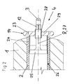
- Fig. 2 shows the working end of a second inventive working electrode in longitudinal section, which essentially corresponds in construction to the above-described working electrode.
- the inner conductor 2 is formed in the present case as a pure cylinder sleeve without radial bead and the abutment member 29 as a disk-shaped Stirnlochmutter with four end holes 23 and rounded peripheral edges, which here form the radial bead 14 of the field relief.
- the expansion sleeve 24 in this embodiment is shorter and significantly larger in circumference, the expansion body 25 is rather plate-shaped and visible here the expansion shaft 8 of the drive member 27 is shorter than in the example in Fig. 1 ,
- the insulator body 1, the electrode tip 3, the mirror surfaces 12 and the external thread 28 of the drive element 27 are, however, identical.
- Fig. 3 shows the working end of a third inventive working electrode in longitudinal section.
- the electrode here also comprises a cylindrical insulator body 1 which is of frusto-conical shape towards the working end and in the center of which a central conductor 2 is arranged.
- the central conductor 2 has at its end face on the working end side a central cylindrical bore which, towards the working end, on which the central conductor 2 emerges from the insulator body 1 with the formation of a circumferential radial bead 14, is opened.
- the radial bead 14 is provided with end bores 23 for engaging a face hole key.
- an inventive change part 4 Arranged in the central bore of the central conductor 2 is an inventive change part 4, which in the present case comprises an expansion sleeve 24 and a conical spreader 25 for radially spreading the expansion sleeve 24 by axial displacement relative to the same.
- the expansion body 25 is integrally connected to a drive element 27 for displacing the expansion body 25 in the expansion sleeve 24, which protrudes at its end facing away from the expansion body of the expansion sleeve 24 and is formed at this end as a spherical cap electrode tip 3.
- the drive element 27 also has an external thread 28 which is screwed into a corresponding internal thread at the working end of the expansion sleeve 24.
- This area of the expansion sleeve 24 forms a claimed abutment element.
- Spreader body 25, drive member 27, external thread 28 and electrode tip 3 are thus formed here of a one-piece Einschraubteil, which also has mirror surfaces 12 for cooperation with an insertion or Ausschraubtechnikmaschine and when screwing into the expansion sleeve 24 automatically a spread and corresponding clamping of the same in the bore in the central conductor 2 causes. So that no torsional forces are introduced into the contact surface between the central conductor 2 and the insulator body 1, the central conductor 2 is expediently secured against twisting when screwing in or unscrewing this screw-in part with a face-hole key.
Landscapes
- Health & Medical Sciences (AREA)
- Toxicology (AREA)
- Engineering & Computer Science (AREA)
- Food Science & Technology (AREA)
- Disintegrating Or Milling (AREA)
- Prevention Of Electric Corrosion (AREA)
- Electrodes For Compound Or Non-Metal Manufacture (AREA)
- Electrical Discharge Machining, Electrochemical Machining, And Combined Machining (AREA)
- Discharge Heating (AREA)
Applications Claiming Priority (2)
| Application Number | Priority Date | Filing Date | Title |
|---|---|---|---|
| PCT/CH2006/000100 WO2007093063A1 (fr) | 2006-02-15 | 2006-02-15 | Électrode active pour un équipement de fragmentation électrodynamique |
| EP06701855A EP2026907B1 (fr) | 2006-02-15 | 2006-02-15 | Électrode active pour un équipement de fragmentation électrodynamique |
Related Parent Applications (1)
| Application Number | Title | Priority Date | Filing Date |
|---|---|---|---|
| EP06701855.6 Division | 2006-02-15 |
Publications (2)
| Publication Number | Publication Date |
|---|---|
| EP2266701A1 true EP2266701A1 (fr) | 2010-12-29 |
| EP2266701B1 EP2266701B1 (fr) | 2012-03-14 |
Family
ID=37045918
Family Applications (2)
| Application Number | Title | Priority Date | Filing Date |
|---|---|---|---|
| EP06701855A Active EP2026907B1 (fr) | 2006-02-15 | 2006-02-15 | Électrode active pour un équipement de fragmentation électrodynamique |
| EP10009321A Not-in-force EP2266701B1 (fr) | 2006-02-15 | 2006-02-15 | Electrode de travail pour une installation de fragmentation électrodynamique |
Family Applications Before (1)
| Application Number | Title | Priority Date | Filing Date |
|---|---|---|---|
| EP06701855A Active EP2026907B1 (fr) | 2006-02-15 | 2006-02-15 | Électrode active pour un équipement de fragmentation électrodynamique |
Country Status (10)
| Country | Link |
|---|---|
| US (1) | US8125129B2 (fr) |
| EP (2) | EP2026907B1 (fr) |
| JP (1) | JP5049297B2 (fr) |
| AT (2) | ATE549089T1 (fr) |
| AU (2) | AU2006338157C1 (fr) |
| CA (1) | CA2642411C (fr) |
| DE (1) | DE502006008364D1 (fr) |
| DK (2) | DK2026907T3 (fr) |
| ES (2) | ES2383785T3 (fr) |
| WO (1) | WO2007093063A1 (fr) |
Families Citing this family (7)
| Publication number | Priority date | Publication date | Assignee | Title |
|---|---|---|---|---|
| DE102010015343B4 (de) * | 2010-04-17 | 2018-04-05 | Borgwarner Ludwigsburg Gmbh | HF-Zündeinrichtung und Verfahren zu ihrer Herstellung |
| WO2013053066A1 (fr) * | 2011-10-10 | 2013-04-18 | Selfrag Ag | Procédé destiné à fragmenter et/ou à pré-affaiblir un matériau au moyen de décharges à haute tension |
| PL2888053T3 (pl) * | 2012-08-24 | 2017-01-31 | Selfrag Ag | Sposób i urządzenie do rozdrabniania i/lub osłabiania materiału za pomocą impulsów wysokonapięciowych |
| CN104736664B (zh) * | 2012-10-17 | 2016-09-14 | 宇部兴产株式会社 | 波长转换部件及使用其的发光装置 |
| CN105845123B (zh) * | 2016-03-21 | 2019-04-19 | 西北工业大学 | 一种大功率水下等离子体强声源的放电电极头 |
| CN109551067B (zh) * | 2019-01-22 | 2023-12-22 | 崇义章源钨业股份有限公司 | 火花机电极 |
| RU2733413C1 (ru) * | 2020-01-14 | 2020-10-01 | Сергей Николаевич Ким | Стойкий рабочий электрод для электрогидравлических и электроимпульсных устройств |
Citations (7)
| Publication number | Priority date | Publication date | Assignee | Title |
|---|---|---|---|---|
| US4458153A (en) | 1982-09-13 | 1984-07-03 | Wesley Richard H | Organism destruction by electrohydraulic discharge within a pulsed magnetic field envelope |
| DE3844419A1 (de) | 1987-12-30 | 1989-07-20 | Viktor Nikolaevic Zacharov | Unterwasserentlader zur zertruemmerung von konkrementen |
| SU1781892A1 (ru) | 1989-12-28 | 1996-08-10 | Экспериментальный кооператив "ЭГИДА-А" | Высоковольтный электрод |
| SU1790069A1 (ru) | 1990-04-06 | 1996-08-10 | Экспериментальный кооператив "ЭГИДА-А" | Высоковольтный электрод установки электрогидравлического дробления |
| JP2003001137A (ja) | 2001-06-19 | 2003-01-07 | Sumitomo Electric Ind Ltd | 破砕装置用電極および破砕装置 |
| US20050150688A1 (en) * | 2002-02-12 | 2005-07-14 | Macgregor Scott J. | Plasma channel drilling process |
| US20050150668A1 (en) | 2003-12-29 | 2005-07-14 | Jim Williamson | Box scraper with scarifier |
Family Cites Families (13)
| Publication number | Priority date | Publication date | Assignee | Title |
|---|---|---|---|---|
| JPS5914893U (ja) * | 1982-07-15 | 1984-01-28 | 青木 直 | 石割り装置 |
| JPS607948A (ja) * | 1983-06-29 | 1985-01-16 | 大山 孝一 | 硬質物破壊装置 |
| JPS6198897A (ja) * | 1984-10-19 | 1986-05-17 | 株式会社 スギノマシン | 脆性物体の破砕方法およびその装置 |
| JPH03113110A (ja) * | 1989-09-25 | 1991-05-14 | Masahiko Kono | アンカーボルト構造体 |
| US5420473A (en) | 1993-10-12 | 1995-05-30 | Thomas; Howard C. | Spark gap electrode assembly for lithotripters |
| JPH09192526A (ja) * | 1996-01-12 | 1997-07-29 | Kobe Steel Ltd | 放電破砕装置 |
| JP2000018227A (ja) * | 1998-07-03 | 2000-01-18 | Hazama Gumi Ltd | 二重ボルト及び位置調整用具 |
| JP2001248623A (ja) * | 2000-03-03 | 2001-09-14 | Mitsubishi Motors Corp | ボルト締結構造 |
| JP3563363B2 (ja) * | 2000-12-08 | 2004-09-08 | 住友電気工業株式会社 | 破砕装置用電極および破砕装置 |
| JP2003126724A (ja) * | 2001-10-26 | 2003-05-07 | Sumitomo Electric Ind Ltd | 同軸導体用コネクタ、破砕装置用電極および破砕装置 |
| JP4326191B2 (ja) * | 2002-07-16 | 2009-09-02 | 株式会社ジェイテクト | ピン型保持器 |
| JP4255305B2 (ja) * | 2003-04-18 | 2009-04-15 | 株式会社小松製作所 | 岩盤破砕用くさび装置並びにそれに用いられるくさびおよびくさびガイド |
| JP2005194832A (ja) * | 2004-01-09 | 2005-07-21 | Sanko Techno Co Ltd | アンカー |
-
2006
- 2006-02-15 ES ES10009321T patent/ES2383785T3/es active Active
- 2006-02-15 AT AT10009321T patent/ATE549089T1/de active
- 2006-02-15 CA CA2642411A patent/CA2642411C/fr not_active Expired - Fee Related
- 2006-02-15 DE DE502006008364T patent/DE502006008364D1/de active Active
- 2006-02-15 WO PCT/CH2006/000100 patent/WO2007093063A1/fr active Application Filing
- 2006-02-15 AT AT06701855T patent/ATE488299T1/de active
- 2006-02-15 EP EP06701855A patent/EP2026907B1/fr active Active
- 2006-02-15 DK DK06701855.6T patent/DK2026907T3/da active
- 2006-02-15 ES ES06701855T patent/ES2353901T3/es active Active
- 2006-02-15 US US12/278,750 patent/US8125129B2/en active Active
- 2006-02-15 AU AU2006338157A patent/AU2006338157C1/en not_active Ceased
- 2006-02-15 EP EP10009321A patent/EP2266701B1/fr not_active Not-in-force
- 2006-02-15 JP JP2008554572A patent/JP5049297B2/ja not_active Expired - Fee Related
- 2006-02-15 DK DK10009321.0T patent/DK2266701T3/da active
-
2011
- 2011-01-11 AU AU2011200094A patent/AU2011200094B2/en not_active Ceased
Patent Citations (7)
| Publication number | Priority date | Publication date | Assignee | Title |
|---|---|---|---|---|
| US4458153A (en) | 1982-09-13 | 1984-07-03 | Wesley Richard H | Organism destruction by electrohydraulic discharge within a pulsed magnetic field envelope |
| DE3844419A1 (de) | 1987-12-30 | 1989-07-20 | Viktor Nikolaevic Zacharov | Unterwasserentlader zur zertruemmerung von konkrementen |
| SU1781892A1 (ru) | 1989-12-28 | 1996-08-10 | Экспериментальный кооператив "ЭГИДА-А" | Высоковольтный электрод |
| SU1790069A1 (ru) | 1990-04-06 | 1996-08-10 | Экспериментальный кооператив "ЭГИДА-А" | Высоковольтный электрод установки электрогидравлического дробления |
| JP2003001137A (ja) | 2001-06-19 | 2003-01-07 | Sumitomo Electric Ind Ltd | 破砕装置用電極および破砕装置 |
| US20050150688A1 (en) * | 2002-02-12 | 2005-07-14 | Macgregor Scott J. | Plasma channel drilling process |
| US20050150668A1 (en) | 2003-12-29 | 2005-07-14 | Jim Williamson | Box scraper with scarifier |
Non-Patent Citations (2)
| Title |
|---|
| DATABASE WPI Week 199712, Derwent World Patents Index; AN 1997-130988, XP002402088 * |
| DATABASE WPI Week 199712, Derwent World Patents Index; AN 1997-131002, XP002402087 * |
Also Published As
| Publication number | Publication date |
|---|---|
| AU2006338157C1 (en) | 2011-05-19 |
| AU2006338157B2 (en) | 2010-11-11 |
| WO2007093063A1 (fr) | 2007-08-23 |
| EP2026907B1 (fr) | 2010-11-17 |
| DK2266701T3 (da) | 2012-07-09 |
| EP2026907A1 (fr) | 2009-02-25 |
| JP5049297B2 (ja) | 2012-10-17 |
| CA2642411C (fr) | 2013-08-13 |
| US8125129B2 (en) | 2012-02-28 |
| US20090153009A1 (en) | 2009-06-18 |
| JP2009526636A (ja) | 2009-07-23 |
| EP2266701B1 (fr) | 2012-03-14 |
| ATE488299T1 (de) | 2010-12-15 |
| ATE549089T1 (de) | 2012-03-15 |
| DE502006008364D1 (de) | 2010-12-30 |
| AU2011200094B2 (en) | 2013-01-10 |
| CA2642411A1 (fr) | 2007-08-23 |
| AU2006338157A1 (en) | 2007-08-23 |
| ES2383785T3 (es) | 2012-06-26 |
| ES2353901T3 (es) | 2011-03-08 |
| AU2011200094A1 (en) | 2011-01-27 |
| DK2026907T3 (da) | 2011-02-28 |
Similar Documents
| Publication | Publication Date | Title |
|---|---|---|
| EP2266701B1 (fr) | Electrode de travail pour une installation de fragmentation électrodynamique | |
| DE102005024206B4 (de) | Überspannungsableiter mit Käfig-Design | |
| DE102011101096A1 (de) | Bolzen und Spannsystem mit Bolzen | |
| WO2017194633A1 (fr) | Vis pédiculaire présentant un filetage à os de grand diamètre | |
| EP2025951A2 (fr) | Unité de cylindre-piston | |
| EP3658785B1 (fr) | Boulon d'écartement et ensemble de liaison comportant un tel boulon d'écartement | |
| DE102012103672A1 (de) | Abreißschraube | |
| DE102006048177A1 (de) | Befestigungsmittel, insbesondere Abreißschraube, mit abtrennbarem Klemmabschnitt | |
| DE102009012243B4 (de) | Stanzmutter, Stanzmutter-Vorrichtung und Stanzmutter-Blechverbindung | |
| DE102010043167A1 (de) | Vorrichtung zur Drehmomentbegrenzung | |
| DE2546641B2 (de) | Zweiteiliger Befestiger für Metallbleche, insbesondere für Blechverbindungen im Flugzeugbau mit Blechen aus Titan und Aluminium | |
| EP3715648A1 (fr) | Système de serrage, utilisation d'un disque de serrage et procédé de précontrainte d'un élément de fixation | |
| DE102008039431B4 (de) | Abreißschraube für Verbindungselemente von elektrischen Leitern | |
| DE102018132838A1 (de) | Ultraschallschweißanlage mit Halterung | |
| EP3280920B1 (fr) | Raccordement réversible de composants mécaniques | |
| DE102018117366B4 (de) | Einsatz zur Verbindung eines elektrischen Anschlusses mit einer Wand, Demontagewerkzeug und Ausrichtungswerkzeug für einen Einsatz sowie Verfahren zur Reparatur eines Einsatzes | |
| EP2865903A1 (fr) | Ancrage expansible avec élément élastique | |
| EP0514924B1 (fr) | Vis de contact | |
| EP3763953A1 (fr) | Écrou et collier de serrage doté d'un tel écrou | |
| EP2604361B1 (fr) | Dispositif de coin de serrage pour la fixation d'outils sur des machines-outils | |
| DE10162094A1 (de) | Heftnadel | |
| EP1731750B1 (fr) | Dispositif avec jonction de perçages | |
| DE19847464C2 (de) | Einsatz für Gewindebohrer | |
| DE10112473C1 (de) | Spannsatz zur kraftschlüssigen Verbindung von Welle und Nabe | |
| DE19516129B4 (de) | Selbstsichernde Mutter |
Legal Events
| Date | Code | Title | Description |
|---|---|---|---|
| PUAI | Public reference made under article 153(3) epc to a published international application that has entered the european phase |
Free format text: ORIGINAL CODE: 0009012 |
|
| 17P | Request for examination filed |
Effective date: 20100908 |
|
| AC | Divisional application: reference to earlier application |
Ref document number: 2026907 Country of ref document: EP Kind code of ref document: P |
|
| AK | Designated contracting states |
Kind code of ref document: A1 Designated state(s): AT BE BG CH CY CZ DE DK EE ES FI FR GB GR HU IE IS IT LI LT LU LV MC NL PL PT RO SE SI SK TR |
|
| GRAP | Despatch of communication of intention to grant a patent |
Free format text: ORIGINAL CODE: EPIDOSNIGR1 |
|
| RIC1 | Information provided on ipc code assigned before grant |
Ipc: G10K 15/06 20060101ALI20110826BHEP Ipc: B02C 19/18 20060101AFI20110826BHEP |
|
| GRAS | Grant fee paid |
Free format text: ORIGINAL CODE: EPIDOSNIGR3 |
|
| GRAA | (expected) grant |
Free format text: ORIGINAL CODE: 0009210 |
|
| AC | Divisional application: reference to earlier application |
Ref document number: 2026907 Country of ref document: EP Kind code of ref document: P |
|
| AK | Designated contracting states |
Kind code of ref document: B1 Designated state(s): AT BE BG CH CY CZ DE DK EE ES FI FR GB GR HU IE IS IT LI LT LU LV MC NL PL PT RO SE SI SK TR |
|
| REG | Reference to a national code |
Ref country code: GB Ref legal event code: FG4D Free format text: NOT ENGLISH |
|
| REG | Reference to a national code |
Ref country code: CH Ref legal event code: NV Representative=s name: E. BLUM & CO. AG PATENT- UND MARKENANWAELTE VSP Ref country code: CH Ref legal event code: EP Ref country code: AT Ref legal event code: REF Ref document number: 549089 Country of ref document: AT Kind code of ref document: T Effective date: 20120315 |
|
| REG | Reference to a national code |
Ref country code: IE Ref legal event code: FG4D Free format text: LANGUAGE OF EP DOCUMENT: GERMAN |
|
| REG | Reference to a national code |
Ref country code: DE Ref legal event code: R096 Ref document number: 502006011140 Country of ref document: DE Effective date: 20120510 |
|
| REG | Reference to a national code |
Ref country code: SE Ref legal event code: TRGR |
|
| REG | Reference to a national code |
Ref country code: NL Ref legal event code: T3 |
|
| REG | Reference to a national code |
Ref country code: ES Ref legal event code: FG2A Ref document number: 2383785 Country of ref document: ES Kind code of ref document: T3 Effective date: 20120626 |
|
| REG | Reference to a national code |
Ref country code: DK Ref legal event code: T3 |
|
| PG25 | Lapsed in a contracting state [announced via postgrant information from national office to epo] |
Ref country code: LT Free format text: LAPSE BECAUSE OF FAILURE TO SUBMIT A TRANSLATION OF THE DESCRIPTION OR TO PAY THE FEE WITHIN THE PRESCRIBED TIME-LIMIT Effective date: 20120314 |
|
| LTIE | Lt: invalidation of european patent or patent extension |
Effective date: 20120314 |
|
| PG25 | Lapsed in a contracting state [announced via postgrant information from national office to epo] |
Ref country code: GR Free format text: LAPSE BECAUSE OF FAILURE TO SUBMIT A TRANSLATION OF THE DESCRIPTION OR TO PAY THE FEE WITHIN THE PRESCRIBED TIME-LIMIT Effective date: 20120615 Ref country code: LV Free format text: LAPSE BECAUSE OF FAILURE TO SUBMIT A TRANSLATION OF THE DESCRIPTION OR TO PAY THE FEE WITHIN THE PRESCRIBED TIME-LIMIT Effective date: 20120314 |
|
| PG25 | Lapsed in a contracting state [announced via postgrant information from national office to epo] |
Ref country code: CY Free format text: LAPSE BECAUSE OF FAILURE TO SUBMIT A TRANSLATION OF THE DESCRIPTION OR TO PAY THE FEE WITHIN THE PRESCRIBED TIME-LIMIT Effective date: 20120314 |
|
| PG25 | Lapsed in a contracting state [announced via postgrant information from national office to epo] |
Ref country code: RO Free format text: LAPSE BECAUSE OF FAILURE TO SUBMIT A TRANSLATION OF THE DESCRIPTION OR TO PAY THE FEE WITHIN THE PRESCRIBED TIME-LIMIT Effective date: 20120314 Ref country code: EE Free format text: LAPSE BECAUSE OF FAILURE TO SUBMIT A TRANSLATION OF THE DESCRIPTION OR TO PAY THE FEE WITHIN THE PRESCRIBED TIME-LIMIT Effective date: 20120314 Ref country code: PL Free format text: LAPSE BECAUSE OF FAILURE TO SUBMIT A TRANSLATION OF THE DESCRIPTION OR TO PAY THE FEE WITHIN THE PRESCRIBED TIME-LIMIT Effective date: 20120314 Ref country code: SI Free format text: LAPSE BECAUSE OF FAILURE TO SUBMIT A TRANSLATION OF THE DESCRIPTION OR TO PAY THE FEE WITHIN THE PRESCRIBED TIME-LIMIT Effective date: 20120314 Ref country code: IS Free format text: LAPSE BECAUSE OF FAILURE TO SUBMIT A TRANSLATION OF THE DESCRIPTION OR TO PAY THE FEE WITHIN THE PRESCRIBED TIME-LIMIT Effective date: 20120714 |
|
| PG25 | Lapsed in a contracting state [announced via postgrant information from national office to epo] |
Ref country code: SK Free format text: LAPSE BECAUSE OF FAILURE TO SUBMIT A TRANSLATION OF THE DESCRIPTION OR TO PAY THE FEE WITHIN THE PRESCRIBED TIME-LIMIT Effective date: 20120314 Ref country code: PT Free format text: LAPSE BECAUSE OF FAILURE TO SUBMIT A TRANSLATION OF THE DESCRIPTION OR TO PAY THE FEE WITHIN THE PRESCRIBED TIME-LIMIT Effective date: 20120716 |
|
| PLBE | No opposition filed within time limit |
Free format text: ORIGINAL CODE: 0009261 |
|
| STAA | Information on the status of an ep patent application or granted ep patent |
Free format text: STATUS: NO OPPOSITION FILED WITHIN TIME LIMIT |
|
| 26N | No opposition filed |
Effective date: 20121217 |
|
| REG | Reference to a national code |
Ref country code: DE Ref legal event code: R097 Ref document number: 502006011140 Country of ref document: DE Effective date: 20121217 |
|
| PG25 | Lapsed in a contracting state [announced via postgrant information from national office to epo] |
Ref country code: BG Free format text: LAPSE BECAUSE OF FAILURE TO SUBMIT A TRANSLATION OF THE DESCRIPTION OR TO PAY THE FEE WITHIN THE PRESCRIBED TIME-LIMIT Effective date: 20120614 |
|
| PG25 | Lapsed in a contracting state [announced via postgrant information from national office to epo] |
Ref country code: MC Free format text: LAPSE BECAUSE OF NON-PAYMENT OF DUE FEES Effective date: 20130228 |
|
| PG25 | Lapsed in a contracting state [announced via postgrant information from national office to epo] |
Ref country code: LU Free format text: LAPSE BECAUSE OF NON-PAYMENT OF DUE FEES Effective date: 20130215 Ref country code: HU Free format text: LAPSE BECAUSE OF FAILURE TO SUBMIT A TRANSLATION OF THE DESCRIPTION OR TO PAY THE FEE WITHIN THE PRESCRIBED TIME-LIMIT; INVALID AB INITIO Effective date: 20060215 |
|
| REG | Reference to a national code |
Ref country code: FR Ref legal event code: PLFP Year of fee payment: 11 |
|
| REG | Reference to a national code |
Ref country code: FR Ref legal event code: PLFP Year of fee payment: 12 |
|
| PGFP | Annual fee paid to national office [announced via postgrant information from national office to epo] |
Ref country code: SE Payment date: 20170216 Year of fee payment: 12 Ref country code: FR Payment date: 20170217 Year of fee payment: 12 Ref country code: CH Payment date: 20170109 Year of fee payment: 12 Ref country code: FI Payment date: 20170213 Year of fee payment: 12 Ref country code: DE Payment date: 20170217 Year of fee payment: 12 |
|
| PGFP | Annual fee paid to national office [announced via postgrant information from national office to epo] |
Ref country code: IE Payment date: 20170220 Year of fee payment: 12 Ref country code: NL Payment date: 20170216 Year of fee payment: 12 Ref country code: AT Payment date: 20170217 Year of fee payment: 12 Ref country code: DK Payment date: 20170216 Year of fee payment: 12 Ref country code: BE Payment date: 20170216 Year of fee payment: 12 Ref country code: CZ Payment date: 20170214 Year of fee payment: 12 Ref country code: GB Payment date: 20170216 Year of fee payment: 12 |
|
| PGFP | Annual fee paid to national office [announced via postgrant information from national office to epo] |
Ref country code: TR Payment date: 20170125 Year of fee payment: 12 Ref country code: ES Payment date: 20170213 Year of fee payment: 12 Ref country code: IT Payment date: 20170221 Year of fee payment: 12 |
|
| REG | Reference to a national code |
Ref country code: DE Ref legal event code: R119 Ref document number: 502006011140 Country of ref document: DE |
|
| REG | Reference to a national code |
Ref country code: CH Ref legal event code: PL |
|
| REG | Reference to a national code |
Ref country code: DK Ref legal event code: EBP Effective date: 20180228 |
|
| REG | Reference to a national code |
Ref country code: SE Ref legal event code: EUG |
|
| REG | Reference to a national code |
Ref country code: NL Ref legal event code: MM Effective date: 20180301 |
|
| REG | Reference to a national code |
Ref country code: AT Ref legal event code: MM01 Ref document number: 549089 Country of ref document: AT Kind code of ref document: T Effective date: 20180215 |
|
| GBPC | Gb: european patent ceased through non-payment of renewal fee |
Effective date: 20180215 |
|
| PG25 | Lapsed in a contracting state [announced via postgrant information from national office to epo] |
Ref country code: SE Free format text: LAPSE BECAUSE OF NON-PAYMENT OF DUE FEES Effective date: 20180216 Ref country code: FI Free format text: LAPSE BECAUSE OF NON-PAYMENT OF DUE FEES Effective date: 20180215 |
|
| REG | Reference to a national code |
Ref country code: BE Ref legal event code: MM Effective date: 20180228 |
|
| PG25 | Lapsed in a contracting state [announced via postgrant information from national office to epo] |
Ref country code: CZ Free format text: LAPSE BECAUSE OF NON-PAYMENT OF DUE FEES Effective date: 20180215 Ref country code: LI Free format text: LAPSE BECAUSE OF NON-PAYMENT OF DUE FEES Effective date: 20180228 Ref country code: AT Free format text: LAPSE BECAUSE OF NON-PAYMENT OF DUE FEES Effective date: 20180215 Ref country code: CH Free format text: LAPSE BECAUSE OF NON-PAYMENT OF DUE FEES Effective date: 20180228 |
|
| REG | Reference to a national code |
Ref country code: FR Ref legal event code: ST Effective date: 20181031 |
|
| REG | Reference to a national code |
Ref country code: IE Ref legal event code: MM4A |
|
| PG25 | Lapsed in a contracting state [announced via postgrant information from national office to epo] |
Ref country code: NL Free format text: LAPSE BECAUSE OF NON-PAYMENT OF DUE FEES Effective date: 20180301 |
|
| PG25 | Lapsed in a contracting state [announced via postgrant information from national office to epo] |
Ref country code: DE Free format text: LAPSE BECAUSE OF NON-PAYMENT OF DUE FEES Effective date: 20180901 Ref country code: DK Free format text: LAPSE BECAUSE OF NON-PAYMENT OF DUE FEES Effective date: 20180228 Ref country code: IE Free format text: LAPSE BECAUSE OF NON-PAYMENT OF DUE FEES Effective date: 20180215 |
|
| PG25 | Lapsed in a contracting state [announced via postgrant information from national office to epo] |
Ref country code: BE Free format text: LAPSE BECAUSE OF NON-PAYMENT OF DUE FEES Effective date: 20180228 Ref country code: IT Free format text: LAPSE BECAUSE OF NON-PAYMENT OF DUE FEES Effective date: 20180215 Ref country code: GB Free format text: LAPSE BECAUSE OF NON-PAYMENT OF DUE FEES Effective date: 20180215 Ref country code: FR Free format text: LAPSE BECAUSE OF NON-PAYMENT OF DUE FEES Effective date: 20180228 |
|
| REG | Reference to a national code |
Ref country code: ES Ref legal event code: FD2A Effective date: 20190801 |
|
| PG25 | Lapsed in a contracting state [announced via postgrant information from national office to epo] |
Ref country code: ES Free format text: LAPSE BECAUSE OF NON-PAYMENT OF DUE FEES Effective date: 20180216 |
|
| PG25 | Lapsed in a contracting state [announced via postgrant information from national office to epo] |
Ref country code: TR Free format text: LAPSE BECAUSE OF NON-PAYMENT OF DUE FEES Effective date: 20180215 |