EP2266701A1 - Work electrode for an electrodynamic fragmentation assembly - Google Patents
Work electrode for an electrodynamic fragmentation assembly Download PDFInfo
- Publication number
- EP2266701A1 EP2266701A1 EP10009321A EP10009321A EP2266701A1 EP 2266701 A1 EP2266701 A1 EP 2266701A1 EP 10009321 A EP10009321 A EP 10009321A EP 10009321 A EP10009321 A EP 10009321A EP 2266701 A1 EP2266701 A1 EP 2266701A1
- Authority
- EP
- European Patent Office
- Prior art keywords
- expansion sleeve
- expansion
- working electrode
- central conductor
- working
- Prior art date
- Legal status (The legal status is an assumption and is not a legal conclusion. Google has not performed a legal analysis and makes no representation as to the accuracy of the status listed.)
- Granted
Links
- 238000013467 fragmentation Methods 0.000 title claims description 10
- 238000006062 fragmentation reaction Methods 0.000 title claims description 10
- 230000005520 electrodynamics Effects 0.000 title claims description 9
- 239000004020 conductor Substances 0.000 claims abstract description 50
- 239000012212 insulator Substances 0.000 claims abstract description 21
- 230000007480 spreading Effects 0.000 claims description 20
- 230000008859 change Effects 0.000 claims description 14
- 238000006073 displacement reaction Methods 0.000 claims description 14
- 239000011324 bead Substances 0.000 claims description 11
- 230000000694 effects Effects 0.000 claims description 3
- 238000000034 method Methods 0.000 claims description 3
- 230000008569 process Effects 0.000 claims description 3
- 238000013461 design Methods 0.000 claims description 2
- 239000012530 fluid Substances 0.000 claims description 2
- 230000035515 penetration Effects 0.000 claims description 2
- 239000002893 slag Substances 0.000 claims description 2
- 239000000463 material Substances 0.000 description 7
- 238000010276 construction Methods 0.000 description 5
- 230000015556 catabolic process Effects 0.000 description 4
- 230000008901 benefit Effects 0.000 description 3
- 230000015572 biosynthetic process Effects 0.000 description 3
- 238000011109 contamination Methods 0.000 description 2
- 230000006378 damage Effects 0.000 description 2
- 230000002093 peripheral effect Effects 0.000 description 2
- 230000010349 pulsation Effects 0.000 description 2
- 238000005476 soldering Methods 0.000 description 2
- 229910001220 stainless steel Inorganic materials 0.000 description 2
- 239000010935 stainless steel Substances 0.000 description 2
- 238000003466 welding Methods 0.000 description 2
- RYGMFSIKBFXOCR-UHFFFAOYSA-N Copper Chemical compound [Cu] RYGMFSIKBFXOCR-UHFFFAOYSA-N 0.000 description 1
- XAGFODPZIPBFFR-UHFFFAOYSA-N aluminium Chemical compound [Al] XAGFODPZIPBFFR-UHFFFAOYSA-N 0.000 description 1
- 229910052782 aluminium Inorganic materials 0.000 description 1
- 230000005540 biological transmission Effects 0.000 description 1
- 229910010293 ceramic material Inorganic materials 0.000 description 1
- 239000007795 chemical reaction product Substances 0.000 description 1
- 229910052802 copper Inorganic materials 0.000 description 1
- 239000010949 copper Substances 0.000 description 1
- 230000008878 coupling Effects 0.000 description 1
- 238000010168 coupling process Methods 0.000 description 1
- 238000005859 coupling reaction Methods 0.000 description 1
- 230000001419 dependent effect Effects 0.000 description 1
- 238000004090 dissolution Methods 0.000 description 1
- 239000007772 electrode material Substances 0.000 description 1
- 238000003780 insertion Methods 0.000 description 1
- 230000037431 insertion Effects 0.000 description 1
- 238000009434 installation Methods 0.000 description 1
- 239000007788 liquid Substances 0.000 description 1
- 238000012423 maintenance Methods 0.000 description 1
- 239000007769 metal material Substances 0.000 description 1
- 230000007935 neutral effect Effects 0.000 description 1
- 238000012549 training Methods 0.000 description 1
- XLYOFNOQVPJJNP-UHFFFAOYSA-N water Substances O XLYOFNOQVPJJNP-UHFFFAOYSA-N 0.000 description 1
Images


Classifications
-
- B—PERFORMING OPERATIONS; TRANSPORTING
- B02—CRUSHING, PULVERISING, OR DISINTEGRATING; PREPARATORY TREATMENT OF GRAIN FOR MILLING
- B02C—CRUSHING, PULVERISING, OR DISINTEGRATING IN GENERAL; MILLING GRAIN
- B02C19/00—Other disintegrating devices or methods
- B02C19/18—Use of auxiliary physical effects, e.g. ultrasonics, irradiation, for disintegrating
- B02C2019/183—Crushing by discharge of high electrical energy
Landscapes
- Health & Medical Sciences (AREA)
- Toxicology (AREA)
- Engineering & Computer Science (AREA)
- Food Science & Technology (AREA)
- Disintegrating Or Milling (AREA)
- Prevention Of Electric Corrosion (AREA)
- Electrodes For Compound Or Non-Metal Manufacture (AREA)
- Electrical Discharge Machining, Electrochemical Machining, And Combined Machining (AREA)
- Discharge Heating (AREA)
Abstract
Description
Die Erfindung betrifft eine Arbeitselektrode für eine elektrodynamische Fragmentierungsanlage, Wechselteile für eine solche Arbeitselektrode sowie eine Verwendung der Arbeitselektrode gemäss den Oberbegriffen der unabhängigen Patentansprüche.The invention relates to a working electrode for an electrodynamic fragmentation system, change parts for such a working electrode and a use of the working electrode according to the preambles of the independent claims.
Bei der elektrodynamischen Fragmentierung von Material, wie beispielsweise Beton, werden zwischen einer mit Hochspannungspulsen beaufschlagten Arbeitselektrode und einer üblicherweise auf neutralem Potential liegenden Basiselektrode Hochspannungsdurchschläge durch das zu zerkleinernde Material erzeugt, wodurch es zur Zerkleinerung des Materials kommt. Dabei findet bei jedem Hochspannungsdurchschlag auch ein geringfügiger Materialabtrag an der Arbeitselektrodenspitze statt, so dass diese nach einer gewissen Einsatzdauer abgenutzt ist und ausgetauscht werden muss. Auch kann ein Elektrodenwechsel bei einem Wechsel des mit der Anlage aufzuschliessenden Materials erforderlich werden, um eine Kontamination des Endprodukts mit unerwünschtem Elektrodenmaterial zu verhindern. In beiden Fällen muss bei elektrodynamischen Fragmentierungsanlagen mit nicht austauschbaren Elektrodenspitzen die gesamte Arbeitselektrode inklusive Isolator ausgewechselt werden, was ein kosten- und zeitintensives Unterfangen darstellt, nicht zuletzt deshalb, weil die Arbeitselektroden auf ihrer Anschlussseite üblicherweise an ein mit Isolatoröl gefülltes System angekoppelt sind. Als weiterer Nachteil ergibt sich hieraus, dass es unwirtschaftlich ist, nicht vollständig verbrauchte Elektroden aufzubrauchen, da der Installationsaufwand gemessen an der Restnutzungsdauer relativ hoch ist.In the electrodynamic fragmentation of material, such as concrete, high voltage breakdowns are produced by a working electrode applied to high voltage pulses and a base electrode, which is usually at a neutral potential, through the material to be comminuted, which leads to the comminution of the material. In this case, a slight removal of material at the working electrode tip takes place at each high-voltage breakdown, so that it is worn after a certain period of use and must be replaced. It may also be necessary to change the electrode when changing the material to be digested with the equipment in order to prevent contamination of the end product with unwanted electrode material. In both cases, in electrodynamic fragmentation systems with non-exchangeable electrode tips, the entire working electrode including insulator must be replaced, which is a costly and time-consuming endeavor, not least because the working electrodes are usually coupled on their terminal side to a system filled with insulator oil. A further disadvantage results from the fact that it is uneconomical, not completely used electrodes use up, since the installation costs measured relative to the remaining useful life is relatively high.
Aus dem Stand der Technik sind weiter Hochspannungselektroden bekannt, bei denen die Elektrodenspitze von einem austauschbaren Wechselteil gebildet ist und welche dadurch die zuvor genannten Nachteile weitestgehend vermeiden. Derartige Hochspannungselektroden sind beispielsweise in
Es stellt sich daher die Aufgabe, eine Arbeitselektrode zur Verfügung zu stellen, welche die Nachteile des Standes der Technik nicht aufweist oder diese zumindest teilweise vermeidet.It is therefore the task of providing a working electrode which does not have the disadvantages of the prior art or at least partially avoids it.
Diese Aufgabe wird durch die Arbeitselektrode und die Wechselteile für eine solche Arbeitselektrode gemäss den unabhängigen Patentansprüchen gelöst.This object is achieved by the working electrode and the change parts for such a working electrode according to the independent claims.
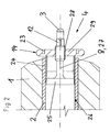
Demgemäss betrifft ein erster Aspekt der Erfindung eine Arbeitselektrode für eine elektrodynamische Fragmentierungsanlage mit einer austauschbaren Elektrodenspitze. Die Arbeitselektrode umfasst einen Isolatorkörper, z.B. aus Kunststoff oder aus einem keramischen Material, mit einem zentralen Leiter aus einem elektrisch gut leitenden, bevorzugterweise metallischen Material, z.B. aus Aluminium, Kupfer oder rostfreiem Stahl, welcher den Isolator axial durchsetzt. An einem Ende ist der zentrale Leiter ausgestaltet zur Ankopplung an einen Hochspannungsgenerator zur Beschickung der Arbeitselektrode mit Hochspannungspulsen. An seinem anderen Ende, dem sogenannten Arbeitsende, welches im Betrieb in den mit Prozessflüssigkeit, z.B. Wasser, und dem zu zerkleinernden Material gefüllten Arbeitsbereich der Fragmentierungsanlage eintaucht, trägt der zentrale Leiter eine Elektrodenspitze, welche im Betrieb den Ausgangspunkt für die Spannungsdurchschläge bildet. Die Elektrodenspitze wird von einem austauschbaren, einstückigen oder mehrteiligen Wechselteil gebildet.Accordingly, a first aspect of the invention relates to a working electrode for an electrodynamic fragmentation system with a replaceable electrode tip. The working electrode comprises an insulator body, for example made of plastic or of a ceramic material, with a central conductor of a highly electrically conductive, preferably metallic material, for example of aluminum, copper or stainless steel, which passes through the insulator axially. At one end of the central conductor is designed for coupling to a high voltage generator for charging the working electrode with high voltage pulses. At its other end, the so-called working end, which dips in operation in the filled with process fluid, eg water, and the material to be crushed workspace of the fragmentation, the central conductor carries an electrode tip, which forms the starting point for the voltage breakdown in operation. The electrode tip is formed by a replaceable, one-piece or multi-part removable part.
Das Wechselteil ist kraftschlüssig durch Klemmung in einer stirnseitigen Öffnung im Arbeitsende des zentralen Leiters befestigt, was bevorzugterweise dadurch bewerkstelligt wird, dass das Wechselteil eine bevorzugterweise zylindrische Spreizhülse und einen zumindest teilweise in der Spreizhülse angeordneten Spreizkörper umfasst, mittels welchem die Spreizhülse in einem Bereich derartig aufspreizbar ist, dass sie radial an die Wandung der stirnseitigen Öffnung gepresst wird und dadurch axial unverschieblich in der Öffnung festgeklemmt wird. Hierdurch kann auf einfache Weise eine sichere Befestigung des Wechselteils am zentralen Leiter erreicht werden. Auch weisen derartige Arbeitselektroden den Vorteil auf, dass bei einem Verschleiss der Elektrode oder bei einer Änderung des zu zerkleinernden Materials lediglich die Elektrodenspitze gewechselt werden muss und z.B. ein Öffnen eines ölgefüllten Hochspannungssystems zwecks Austausch der gesamten Arbeitselektrode überflüssig wird. Hierdurch lassen sich die wartungsbedingten Ausfallzeiten und Betriebskosten elektrodynamischer Fragmentierungsanlagen deutlich senken.Dabei ist es von Vorteil, wenn der Spreizkörper mit einem Antriebselement zum axialen Verschieben desselben bezüglich der Spreizhülse zur Bewirkung einer radialen Aufspreizung der Spreizhülse verbunden ist, welches am Arbeitsende des zentralen Leiters aus der stirnseitigen Öffnung austritt und an seinem dem Spreizkörper abgewandten Ende die Elektrodenspitze bildet. Hierdurch kann die Klemmung des Wechselteils im zentralen Leiter auf einfache Weise durch Ausüben einer Axialkraft auf das Antriebselement bewirkt werden. Werden zudem der Spreizkörper und das Antriebselement einstückig miteinander ausgebildet, was bevorzugt ist, so ergibt sich eine besonders einfache und robuste Konstruktion.The removable part is frictionally secured by clamping in an end opening in the working end of the central conductor, which is preferably accomplished by the replacement part comprises a preferably cylindrical expansion sleeve and an at least partially arranged in the expansion sleeve expansion means by which the expansion sleeve in such a spreadable area is that it is pressed radially against the wall of the frontal opening and thereby clamped axially immovable in the opening. As a result, a secure attachment of the removable part can be achieved at the central conductor in a simple manner. Also, such working electrodes have the advantage that when a wear of the electrode or a change in the material to be crushed, only the electrode tip must be changed and, for example, an opening of an oil-filled high-voltage system for the purpose of replacing the entire working electrode is superfluous. It is thereby advantageous to significantly reduce the maintenance-related downtime and operating costs of electrodynamic fragmentation systems. It is advantageous if the expansion body is connected to a drive element for axially displacing it with respect to the expansion sleeve to effect a radial spreading of the expansion sleeve, which protrudes at the working end of the central conductor emerges from the frontal opening and at its end facing away from the spreader end forms the electrode tip. As a result, the clamping of the removable part in the central conductor can be effected in a simple manner by exerting an axial force on the drive element. If, in addition, the expansion body and the drive element are formed integrally with one another, which is preferred, the result is a particularly simple and robust construction.
Auch ist es dabei bevorzugt, wenn der Spreizkörper einen bevorzugterweise kegel- oder pyramidenförmigen Abschnitt zum radialen Aufspreizen der Spreizhülse aufweist oder gesamthaft als Kegel- oder Pyramidenstumpf ausgebildet ist, da hierdurch sehr grosse Spreizkräfte kontrolliert erzeugt werden können.It is also preferred if the expansion body has a preferably cone-shaped or pyramid-shaped section for radial spreading of the expansion sleeve or is formed overall as a cone or truncated pyramid, as this very large expansion forces can be generated in a controlled manner.
Mit Vorteil weist das Antriebselement wischen der Elektrodenspitze und dem Spreizkörper ein Aussengewinde auf, mittels welchem eine axiale Kraft auf dieses ausgeübt werden kann zur Bewirkung einer Verschiebung des Spreizkörpers und einer resultierenden radialen Spreizung und Klemmung der Spreizhülse in der Öffnung im zentralen Leiter. Auf diese Weise lassen sich relativ grosse Verschiebungskräfte kontrolliert bereitstellen.Advantageously, the drive element wipe the electrode tip and the spreader on an external thread, by means of which an axial force can be exerted on this to effect a displacement of the spreader and a resulting radial expansion and clamping of the expansion in the opening in the central conductor. In this way, relatively large displacement forces can be provided in a controlled manner.
Ist dabei der Spreizkörper derartig ausgebildet, dass eine axiale Verschiebung desselben in Richtung zum Arbeitsende des zentralen Leiters hin eine radiale Aufspreizung der Spreizhülse bewirkt, das Antriebselement zum Festklemmen des Wechselteils im zentralen Leiter also Zugkräfte übertragen muss, so ist es von Vorteil, wenn das Aussengewinde des Antriebselements zur Erzeugung der axialen Verschiebungskräfte mit einem entsprechenden Innengewinde eines Widerlagerelements zusammenwirkt, welches sich axial auf der Spreizhülse abstützt. Hierdurch entsteht eine einfache Bauweise mit wenigen Bauteilen.In this case, the expansion body is designed such that an axial displacement of the same towards the working end of the central conductor causes a radial spreading of the expansion sleeve, the drive element for clamping the change part in the central conductor so tensile forces must be transmitted, it is advantageous if the external thread the drive element for generating the axial displacement forces cooperates with a corresponding internal thread of an abutment element, which is supported axially on the expansion sleeve. This results in a simple construction with few components.
Auch ist es dabei bevorzugt, wenn das Widerlagerelement als Sechskantmutter oder als Stirnlochmutter mit mindestens zwei Stirnlöchern ausgebildet ist, welche bevorzugterweise an ihrem Aussenumfang einen umlaufenden, radialen Wulst aufweist, der als Feldentlastung dienen kann.It is also preferred if the abutment element is designed as a hexagon nut or as a face nut with at least two end holes, which preferably have a circumferential, on its outer circumference, has radial bead, which can serve as field relief.
Mit Vorteil weist das Antriebselement dabei zwischen dem Spreizkörper und dem Aussengewinde einen bevorzugterweise als Dehnschaft oder als Dehnhülse ausgebildeten Dehnungsbereich auf, vorteilhafterweise mit einer Länge von mindesten dem Zweifachen, bevorzugterweise mindestens dem Vierfachen des Durchmessers des Aussengewindes.Advantageously, the drive element in this case between the spreader and the external thread on a preferably designed as a shank or as an expansion sleeve expansion region, advantageously with a length of at least twice, preferably at least four times the diameter of the external thread.
Ist hingegen der Spreizkörper derartig ausgebildet, dass eine axiale Verschiebung desselben in Richtung weg vom Arbeitsende des zentralen Leiters eine radiale Aufspreizung der Spreizhülse bewirkt, das Antriebselement zum Festklemmen des Wechselteils im zentralen Leiter also Druckkräfte übertragen muss, so ist es bevorzugt, wenn das Aussengewinde des Antriebselements mit einem entsprechenden Innengewinde eines Widerlagerelements zusammenwirkt, welches axial mit der Spreizhülse verbunden ist zur Übertragung von axialen Zugkräften zwischen dem Widerlagerelement und der Spreizhülse. Ist dabei das Widerlagerelement einstückig mit der Spreizhülse ausgebildet ist, was bevorzugt wird, so ergibt sich eine denkbar kompakte Bauweise mit einem Minimum an Bauteilen.If, however, the expansion body is designed such that an axial displacement of the same in the direction away from the working end of the central conductor causes a radial spreading of the expansion sleeve, the drive element for clamping the change part in the central conductor must therefore transmit compressive forces, it is preferred if the external thread of the Drive element cooperates with a corresponding internal thread of an abutment member which is axially connected to the expansion sleeve for transmitting axial tensile forces between the abutment member and the expansion sleeve. If the abutment element is formed integrally with the expansion sleeve, which is preferred, the result is a conceivably compact construction with a minimum of components.
Mit Vorteil weist dabei die Spreizhülse im Bereich zwischen dem Widerlagerelement und dem Bereich, wo sie vom Spreizkörper radial aufgespreizt wird, einen Dehnungsbereich auf, welcher bevorzugterweise eine Länge von mindesten dem Zweifachen, noch bevorzugter von mindestens dem Vierfachen des Durchmessers des Innengewindes des Widerlagerelements aufweist.Advantageously, in this case, the expansion sleeve in the region between the abutment element and the region where it is spread radially from the spreader, an expansion region, which preferably has a length of at least twice, more preferably at least four times the diameter of the internal thread of the abutment member.
Wie bereits anhand einiger zuvor erwähnter bevorzugter Ausführungsformen dargelegt wurde, lassen sich durch das konstruktive Vorsehen von Dehnbereichen zur Übertragung der für die Erzeugung von Anpresskräften zwischen Bauteilen des austauschbaren Wechselteils und des zentralen Leiters erforderlichen Kräfte Wechselkräfte zwischen diesen Bauteilen auch bei starken Druckpulsationen im Arbeitsraum vermeiden, so dass besonders robuste und über eine lange Zeit wartungsfreie Arbeitselektroden zur Verfügung gestellt werden können.As has already been explained with reference to a few preferred embodiments mentioned above, the constructive provision of expansion areas for transmitting the forces required for the generation of contact forces between components of the exchangeable exchangeable part and the central conductor makes it possible to exchange forces between these components even under strong pressure pulsations in the working area, so that particularly robust and maintenance-free working electrodes can be provided over a long period of time.
Bevorzugterweise weist das Antriebselement zwischen Elektrodenspitze und Spreizkörper einen Bereich mit einem nicht-rotationssymmetrischen Querschnitt auf, bevorzugterweise mindestens zwei parallele Spiegelflächen, welche formschlüssig mit einem Werkzeug wie z.B. einem Gabelschlüssel ergriffen werden können, zwecks Verdrehung des Antriebselements gegenüber der Spreizhülse und/oder vorübergehender Sicherung desselben gegen ein Verdrehen.Preferably, the drive element between electrode tip and spreader has a region with a non-rotationally symmetrical cross section, preferably at least two parallel mirror surfaces, which are positively connected with a tool such. a wrench can be taken, for the purpose of rotation of the drive member relative to the expansion sleeve and / or temporarily securing the same against rotation.
In noch einer weiteren bevorzugten Ausführungsform der Arbeitselektrode ist zwischen dem Wechselteil und dem zentralen Leiter eine Dichtung, bevorzugterweise ein O-Ring angeordnet, zur Verhinderung eines Eindringens von Prozessflüssigkeit und Schmutz in den Befestigungsbereich zwischen dem Wechselteil und dem zentralen Leiter. Insbesondere bei Ausführungsformen, bei denen das Wechselteil über die zuvor erwähnte erste Verschraubung mit dem zentralen Leiter verbunden ist, lässt sich hierdurch eine Verschmutzung und Beschädigung derselben verhindern.In yet another preferred embodiment of the working electrode, a seal, preferably an O-ring, is disposed between the changing part and the central conductor to prevent penetration of process liquid and dirt into the attachment area between the change part and the central conductor. In particular, in embodiments in which the removable part is connected via the aforementioned first screw to the central conductor, thereby a contamination and damage of the same can be prevented.
In noch einer weiteren bevorzugten Ausführungsform der Arbeitselektrode weist der zentrale Leiter im Bereich seines arbeitsseitigen Endes dort, wo er aus dem Isolatorkörper austritt, an seinem Aussenumfang einen umlaufenden, radialen Wulst auf.In yet another preferred embodiment of the working electrode, the central conductor in the region of its working end, where it emerges from the insulator body, on its outer circumference on a circumferential, radial bead.
In noch einer weiteren bevorzugten Ausführungsform der Arbeitselektrode weist der zentrale Leiter im Bereich seines arbeitsendseitigen Austritts aus dem Isolatorkörper einen Bereich mit einem nicht-rotationssymmetrischen Querschnitt auf, bevorzugterweise zwei parallele Spiegelflächen, zum formschlüssigen Zusammenwirken mit einem Werkzeug wie z.B. einem Gabelschlüssel.In yet another preferred embodiment of the working electrode, the central conductor in the region of its Arbeitsendseitigen exit from the insulator body on a region with a non-rotationally symmetrical cross-section, preferably two parallel mirror surfaces, for positive cooperation with a tool such. a fork wrench.
Alternativ oder zusätzlich ist es bevorzugt, wenn der zentrale Leiter an seiner arbeitsendseitigen Stirnseite mindestens zwei Stirnlöchern aufweist zum formschlüssigen Zusammenwirken mit einem Stirnlochschlüssel.Alternatively or additionally, it is preferred if the central conductor at its end of work End face has at least two end holes for positive engagement with a face spanner.
Durch diese Ausgestaltungen wird es möglich, den zentralen Leiter bei der Montage und/oder Demontage des Wechselteils gegen ein Verdrehen im Isolator zu sichern, welches bei kraftschlüssig z.B. durch Einpressen oder Einschrumpfen im Isolator befestigten zentralen Leitern zu einem Sichlösen bzw. Zerstören der Verbindung mit dem Isolator führen könnte.By these embodiments, it is possible to secure the central conductor during assembly and / or disassembly of the removable part against rotation in the insulator, which in force-locking, for example. central conductors secured by press-fitting or shrink-fitting in the insulator could lead to a disintegration or destruction of the connection with the insulator.
Bei bevorzugten Ausführungsformen der Arbeitselektrode ist die Elektrodenspitze als Kugelkalotte oder als Rotationsparaboloid ausgeformt. Solche Formen stellen einen örtlich definierten Durchschlagsausgangspunkt bereit, bei gleichzeitig guter Standzeit der ElektrodenspitzeIn preferred embodiments of the working electrode, the electrode tip is formed as a spherical cap or as a paraboloid of revolution. Such molds provide a locally defined breakdown starting point while maintaining good electrode tip life
Ein zweiter Aspekt der Erfindung betrifft ein Wechselteil für eine Arbeitselektrode gemäss dem ersten Aspekt der Erfindung. Das Wechselteil weist eine Spreizhülse und einen bevorzugterweise kegel- oder pyramidenförmigen Spreizkörper auf, welcher mindestens teilweise innerhalb der Spreizhülse angeordnet ist und derartig mit dieser zusammenwirkt, das die Spreizhülse durch ein axiales Verschieben des Spreizkörpers relativ zu ihr in einem Bereich, bevorzugterweise eine Endbereich der Spreizhülse, radial aufgespreizt werden kann. Dabei ist der Spreizkörper, bevorzugterweise stoffschlüssig, wie z.B. durch einstückige Ausbildung oder durch Löten oder Schweissen, mit einem Antriebselement zum Verschieben des Spreizkörpers in der Spreizhülse verbunden, welches an seinem dem Spreizkörper abgewandten Ende aus der Spreizhülse herausragt und an diesem Ende eine kugelkalottenförmige oder rotationsparaboloidförmige Elektrodenspitze bildet. Zwischen der Elektrodenspitze und dem Spreizkörper weist das Antriebselement ein Aussengewinde auf, auf welchem ein bevorzugterweise mutternartiges Widerlagerelement mit einem entsprechenden Innengewinde angeordnet ist. Das Widerlagerelement stützt sich axial auf der Spreizhülse ab, so dass ein Rotieren desselben relativ zum Antriebselement eine axiale Bewegung des mit dem Antriebselement verbundenen Spreizkörpers in Richtung zur Elektrodenspitze hin bewirken kann, was dann zu einer zunehmende Aufspreizung der Spreizhülse führt.A second aspect of the invention relates to a replacement part for a working electrode according to the first aspect of the invention. The change part has an expansion sleeve and a preferably cone-shaped or pyramid-shaped expansion body, which is arranged at least partially within the expansion sleeve and cooperates with it in such a way that the expansion sleeve by an axial displacement of the expansion body relative to it in a region, preferably an end portion of the expansion sleeve , can be spread radially. Here, the spreader, preferably cohesively, such as by integral training or by soldering or welding, connected to a drive element for moving the spreader in the expansion sleeve, which protrudes at its end remote from the spreader from the expansion sleeve and at this end a kugelkalottenförmige or rotationsparaboloidförmige Electrode tip forms. Between the electrode tip and the expansion body, the drive element has an external thread on which a preferably nut-like abutment element is arranged with a corresponding internal thread is. The abutment member is axially supported on the expansion sleeve, so that a rotation thereof relative to the drive element can cause an axial movement of the expansion element connected to the drive element in the direction of the electrode tip, which then leads to an increasing spreading of the expansion sleeve.
In einer bevorzugten Ausführungsform des Wechselteils ist das Widerlagerelement als Stirnlochmutter ausgebildet, bevorzugterweise mit mindestens zwei, noch bevorzugter mit mindestens vier mit gleicher Teilung verteilten Stirnlöchern. Dabei ist es des Weiteren bevorzugt, wenn die Stirnlochmutter an ihrem Aussenumfang einen umlaufenden, radialen Wulst bildet, und noch bevorzugter, wenn diese im Wesentlichen die Form einer Scheibe mit gerundeten Umfangskanten aufweist. Auf diese Weise kann das Widerlagerelement zusätzlich als Feldentlastung dienen.In a preferred embodiment of the change part, the abutment element is designed as a face nut, preferably with at least two, more preferably with at least four end holes distributed with the same pitch. In this case, it is further preferred if the face-end nut forms an encircling, radial bead on its outer circumference, and more preferably if it has substantially the shape of a disk with rounded peripheral edges. In this way, the abutment element can additionally serve as a field relief.
In einer weiteren bevorzugten Ausführungsform des Wechselteils weist das Antriebselement zwischen dem Spreizkörper und dem Aussengewinde einen bevorzugterweise als Dehnschaft oder als Dehnhülse ausgebildeten Dehnungsbereich auf, bevorzugterweise mit einer Länge von mindesten dem Zweifachen, noch bevorzugter mindestens dem Vierfachen des Durchmessers des Aussengewindes.In a further preferred embodiment of the removable part, the drive element between the spreader and the external thread on a preferably designed as a stretch or expansion sleeve expansion region, preferably with a length of at least twice, more preferably at least four times the diameter of the external thread.
Ein dritter Aspekt der Erfindung betrifft ein Wechselteil für eine Arbeitselektrode gemäss dem ersten Aspekt der Erfindung. Das Wechselteil weist eine Spreizhülse und einen insbesondere kegel- oder pyramidenförmigen Spreizkörper zum radialen Aufspreizen der Spreizhülse durch axiale Verschiebung desselben relativ zur Spreizhülse auf. Dabei ist der Spreizkörper bevorzugterweise stoffschlüssig, wie z.B. durch einstückige Ausbildung oder durch Schweissen oder Löten, mit einem Antriebselement zum Verschieben des Spreizkörpers in der Spreizhülse verbunden. Das Antriebselement ragt an seinem dem Spreizkörper abgewandten Ende aus der Spreizhülse heraus und ist an diesem Ende als kugelkalottenförmige oder eines rotationsparaboloidförmige Elektrodenspitze ausgebildet. Zwischen der Elektrodenspitze und dem Spreizkörper weist das Antriebselement zudem ein Aussengewinde auf, welches mit einem entsprechenden Innengewinde eines Widerlagerelements zusammenwirkt. Das Widerlagerelement ist, bevorzugterweise durch einstückige Ausbildung, mit der Spreizhülse verbunden, so dass eine Übertragung von axialen Zugkräften zwischen dem Widerlagerelement und der Spreizhülse möglich ist und durch Rotation des Antriebselements relativ zum Widerlagerelement eine axiale Bewegung des Spreizkörper in einer Richtung weg von der Elektrodenspitze bewirkt werden kann, was dann zu einer zunehmenden Aufspreizung der Spreizhülse führt.A third aspect of the invention relates to a replacement part for a working electrode according to the first aspect of the invention. The change part has an expansion sleeve and a particular conical or pyramidal expansion body for radially spreading the expansion sleeve by axial displacement of the same relative to the expansion sleeve. In this case, the expansion body is preferably cohesively, such as connected by one-piece design or by welding or soldering, with a drive element for moving the expansion body in the expansion sleeve. The drive element protrudes at its end facing away from the spreader out of the expansion sleeve and is at this end as kugelkalottenförmige or one formed Rotationsparaboloidförmige electrode tip. Between the electrode tip and the expansion body, the drive element also has an external thread which cooperates with a corresponding internal thread of an abutment element. The abutment element is, preferably by integral formation, connected to the expansion sleeve, so that a transmission of axial tensile forces between the abutment element and the expansion sleeve is possible and caused by rotation of the drive element relative to the abutment element axial movement of the spreader in a direction away from the electrode tip can be, which then leads to an increasing spreading of the expansion sleeve.
In einer bevorzugten Ausführungsform des Wechselteils weist die Spreizhülse im Bereich zwischen dem Widerlagerelement und dem Bereich, wo sie vom Spreizkörper radial aufgespreizt wird, einen Dehnungsbereich auf, bevorzugterweise mit einer Länge von mindesten dem Zweifachen, noch bevorzugter mindestens dem Vierfachen des Durchmessers des Innengewindes des Widerlagerelements. Typischerweise sind solche Dehnungsbereiche daran zu erkennen, dass sie einen reduzierten Querschnitt aufweisen um eine möglichst wenig steife Dehnungscharakteristik zu erhalten.In a preferred embodiment of the interchangeable part, the expansion sleeve in the region between the abutment member and the region where it is spread radially from the spreader, an expansion region, preferably with a length of at least twice, more preferably at least four times the diameter of the internal thread of the abutment member , Typically, such strain ranges can be recognized by the fact that they have a reduced cross-section in order to obtain a rigid stiffness characteristic as little as possible.
Die Wechselteile gemäss dem zweiten und dritten Aspekt der Erfindung stellen bevorzugte Handelswaren dar und ermöglichen den Bau von Arbeitselektroden, bei denen die Elektrodenspitze ohne Abkopplung der Elektrode vom Spannungszuführungssystem auf einfache Weise gewechselt werden kann.The change parts according to the second and third aspects of the invention are preferred commercial goods and allow the construction of working electrodes, in which the electrode tip can be changed easily without disconnecting the electrode from the voltage supply system.
Ein vierter Aspekt der Erfindung betrifft die Verwendung der Arbeitselektrode gemäss dem ersten Aspekt der Erfindung zum elektrodynamischen Fragmentieren von bevorzugterweise schlecht leitenden Materialien wie Beton oder Schlacke. Bei solchen Verwendungen treten die Vorteile der Erfindung besonders deutlich zu Tage.A fourth aspect of the invention relates to the use of the working electrode according to the first aspect of the invention for the electrodynamic fragmentation of preferably poorly conductive materials such as concrete or slag. In such uses, the benefits of the invention are particularly evident.
Weitere Ausgestaltungen, Vorteile und Anwendungen der Erfindung ergeben sich aus den abhängigen Ansprüchen und aus der nun folgenden Beschreibung anhand der Figuren. Dabei zeigen:
-
Fig. 1 einen Längsschnitt durch das Arbeitsende einer ersten erfindungsgemässen Arbeitselektrode; -
Fig. 2 einen Längsschnitt durch das Arbeitsende einer zweiten erfindungsgemässen Arbeitselektrode; und -
Fig. 3 einen Längsschnitt durch das Arbeitsende einer dritten erfindungsgemässen Arbeitselektrode.
-
Fig. 1 a longitudinal section through the working end of a first inventive working electrode; -
Fig. 2 a longitudinal section through the working end of a second inventive working electrode; and -
Fig. 3 a longitudinal section through the working end of a third inventive working electrode.
Während in der vorliegenden Anmeldung bevorzugte Ausführungen der Erfindung beschrieben sind, ist klar darauf hinzuweisen, dass die Erfindung nicht auf diese beschränkt ist und auch in anderer Weise innerhalb des Umfangs der nun folgenden Ansprüche ausgeführt werden kann.While preferred embodiments of the invention are described in the present application, it should be clearly understood that the invention is not limited to these and may be practiced otherwise within the scope of the following claims.
Claims (21)
Applications Claiming Priority (2)
| Application Number | Priority Date | Filing Date | Title |
|---|---|---|---|
| PCT/CH2006/000100 WO2007093063A1 (en) | 2006-02-15 | 2006-02-15 | Working electrode for an electrodynamic fragmenting installation |
| EP06701855A EP2026907B1 (en) | 2006-02-15 | 2006-02-15 | Working electrode for an electrodynamic fragmenting installation |
Related Parent Applications (1)
| Application Number | Title | Priority Date | Filing Date |
|---|---|---|---|
| EP06701855.6 Division | 2006-02-15 |
Publications (2)
| Publication Number | Publication Date |
|---|---|
| EP2266701A1 true EP2266701A1 (en) | 2010-12-29 |
| EP2266701B1 EP2266701B1 (en) | 2012-03-14 |
Family
ID=37045918
Family Applications (2)
| Application Number | Title | Priority Date | Filing Date |
|---|---|---|---|
| EP10009321A Not-in-force EP2266701B1 (en) | 2006-02-15 | 2006-02-15 | Work electrode for an electrodynamic fragmentation assembly |
| EP06701855A Active EP2026907B1 (en) | 2006-02-15 | 2006-02-15 | Working electrode for an electrodynamic fragmenting installation |
Family Applications After (1)
| Application Number | Title | Priority Date | Filing Date |
|---|---|---|---|
| EP06701855A Active EP2026907B1 (en) | 2006-02-15 | 2006-02-15 | Working electrode for an electrodynamic fragmenting installation |
Country Status (10)
| Country | Link |
|---|---|
| US (1) | US8125129B2 (en) |
| EP (2) | EP2266701B1 (en) |
| JP (1) | JP5049297B2 (en) |
| AT (2) | ATE488299T1 (en) |
| AU (2) | AU2006338157C1 (en) |
| CA (1) | CA2642411C (en) |
| DE (1) | DE502006008364D1 (en) |
| DK (2) | DK2266701T3 (en) |
| ES (2) | ES2353901T3 (en) |
| WO (1) | WO2007093063A1 (en) |
Families Citing this family (7)
| Publication number | Priority date | Publication date | Assignee | Title |
|---|---|---|---|---|
| DE102010015343B4 (en) * | 2010-04-17 | 2018-04-05 | Borgwarner Ludwigsburg Gmbh | HF ignition device and method for its production |
| JP5963871B2 (en) * | 2011-10-10 | 2016-08-03 | ゼルフラーク アクチエンゲゼルシャフトselFrag AG | Method of fragmenting and / or pre-weakening material using high voltage discharge |
| PL2888053T3 (en) * | 2012-08-24 | 2017-01-31 | Selfrag Ag | Method and device for fragmenting and/or weakening material by means of high-voltage pulses |
| JP5954425B2 (en) * | 2012-10-17 | 2016-07-20 | 宇部興産株式会社 | Wavelength conversion member and light emitting device using the same |
| CN105845123B (en) * | 2016-03-21 | 2019-04-19 | 西北工业大学 | A kind of discharge electrode head of the strong sound source of high-power underwater plasma |
| CN109551067B (en) * | 2019-01-22 | 2023-12-22 | 崇义章源钨业股份有限公司 | spark machine electrode |
| RU2733413C1 (en) * | 2020-01-14 | 2020-10-01 | Сергей Николаевич Ким | Stable working electrode for electrohydraulic and electric pulse devices |
Citations (7)
| Publication number | Priority date | Publication date | Assignee | Title |
|---|---|---|---|---|
| US4458153A (en) | 1982-09-13 | 1984-07-03 | Wesley Richard H | Organism destruction by electrohydraulic discharge within a pulsed magnetic field envelope |
| DE3844419A1 (en) | 1987-12-30 | 1989-07-20 | Viktor Nikolaevic Zacharov | Underwater discharger for crushing concrements |
| SU1790069A1 (en) | 1990-04-06 | 1996-08-10 | Экспериментальный кооператив "ЭГИДА-А" | High-voltage electrode of plant for electrohydraulic grinding |
| SU1781892A1 (en) | 1989-12-28 | 1996-08-10 | Экспериментальный кооператив "ЭГИДА-А" | High-voltage electrode |
| JP2003001137A (en) | 2001-06-19 | 2003-01-07 | Sumitomo Electric Ind Ltd | Crusher electrode and crusher |
| US20050150688A1 (en) * | 2002-02-12 | 2005-07-14 | Macgregor Scott J. | Plasma channel drilling process |
| US20050150668A1 (en) | 2003-12-29 | 2005-07-14 | Jim Williamson | Box scraper with scarifier |
Family Cites Families (13)
| Publication number | Priority date | Publication date | Assignee | Title |
|---|---|---|---|---|
| JPS5914893U (en) * | 1982-07-15 | 1984-01-28 | 青木 直 | stone breaking device |
| JPS607948A (en) * | 1983-06-29 | 1985-01-16 | 大山 孝一 | Hard material destructing apparatus |
| JPS6198897A (en) * | 1984-10-19 | 1986-05-17 | 株式会社 スギノマシン | Method and device for crushing brittle body |
| JPH03113110A (en) * | 1989-09-25 | 1991-05-14 | Masahiko Kono | Structural body of anchor bolt |
| US5420473A (en) * | 1993-10-12 | 1995-05-30 | Thomas; Howard C. | Spark gap electrode assembly for lithotripters |
| JPH09192526A (en) * | 1996-01-12 | 1997-07-29 | Kobe Steel Ltd | Discharge crusher |
| JP2000018227A (en) * | 1998-07-03 | 2000-01-18 | Hazama Gumi Ltd | Double bolt and position regulating tool |
| JP2001248623A (en) * | 2000-03-03 | 2001-09-14 | Mitsubishi Motors Corp | Bolt tightening structure |
| JP3563363B2 (en) * | 2000-12-08 | 2004-09-08 | 住友電気工業株式会社 | Electrode for crusher and crusher |
| JP2003126724A (en) * | 2001-10-26 | 2003-05-07 | Sumitomo Electric Ind Ltd | Connector for coaxial conductors, electrode for crushing apparatus, and crushing apparatus |
| JP4326191B2 (en) * | 2002-07-16 | 2009-09-02 | 株式会社ジェイテクト | Pin type cage |
| JP4255305B2 (en) * | 2003-04-18 | 2009-04-15 | 株式会社小松製作所 | Wedge device for rock crushing, and wedge and wedge guide used therefor |
| JP2005194832A (en) * | 2004-01-09 | 2005-07-21 | Sanko Techno Co Ltd | Anchor |
-
2006
- 2006-02-15 DE DE502006008364T patent/DE502006008364D1/en active Active
- 2006-02-15 EP EP10009321A patent/EP2266701B1/en not_active Not-in-force
- 2006-02-15 US US12/278,750 patent/US8125129B2/en active Active
- 2006-02-15 DK DK10009321.0T patent/DK2266701T3/en active
- 2006-02-15 ES ES06701855T patent/ES2353901T3/en active Active
- 2006-02-15 AT AT06701855T patent/ATE488299T1/en active
- 2006-02-15 AU AU2006338157A patent/AU2006338157C1/en not_active Ceased
- 2006-02-15 EP EP06701855A patent/EP2026907B1/en active Active
- 2006-02-15 AT AT10009321T patent/ATE549089T1/en active
- 2006-02-15 CA CA2642411A patent/CA2642411C/en not_active Expired - Fee Related
- 2006-02-15 WO PCT/CH2006/000100 patent/WO2007093063A1/en active Application Filing
- 2006-02-15 JP JP2008554572A patent/JP5049297B2/en not_active Expired - Fee Related
- 2006-02-15 DK DK06701855.6T patent/DK2026907T3/en active
- 2006-02-15 ES ES10009321T patent/ES2383785T3/en active Active
-
2011
- 2011-01-11 AU AU2011200094A patent/AU2011200094B2/en not_active Ceased
Patent Citations (7)
| Publication number | Priority date | Publication date | Assignee | Title |
|---|---|---|---|---|
| US4458153A (en) | 1982-09-13 | 1984-07-03 | Wesley Richard H | Organism destruction by electrohydraulic discharge within a pulsed magnetic field envelope |
| DE3844419A1 (en) | 1987-12-30 | 1989-07-20 | Viktor Nikolaevic Zacharov | Underwater discharger for crushing concrements |
| SU1781892A1 (en) | 1989-12-28 | 1996-08-10 | Экспериментальный кооператив "ЭГИДА-А" | High-voltage electrode |
| SU1790069A1 (en) | 1990-04-06 | 1996-08-10 | Экспериментальный кооператив "ЭГИДА-А" | High-voltage electrode of plant for electrohydraulic grinding |
| JP2003001137A (en) | 2001-06-19 | 2003-01-07 | Sumitomo Electric Ind Ltd | Crusher electrode and crusher |
| US20050150688A1 (en) * | 2002-02-12 | 2005-07-14 | Macgregor Scott J. | Plasma channel drilling process |
| US20050150668A1 (en) | 2003-12-29 | 2005-07-14 | Jim Williamson | Box scraper with scarifier |
Non-Patent Citations (2)
| Title |
|---|
| DATABASE WPI Week 199712, Derwent World Patents Index; AN 1997-130988, XP002402088 * |
| DATABASE WPI Week 199712, Derwent World Patents Index; AN 1997-131002, XP002402087 * |
Also Published As
| Publication number | Publication date |
|---|---|
| US8125129B2 (en) | 2012-02-28 |
| AU2011200094A1 (en) | 2011-01-27 |
| DK2266701T3 (en) | 2012-07-09 |
| JP5049297B2 (en) | 2012-10-17 |
| ATE488299T1 (en) | 2010-12-15 |
| EP2266701B1 (en) | 2012-03-14 |
| DE502006008364D1 (en) | 2010-12-30 |
| JP2009526636A (en) | 2009-07-23 |
| AU2006338157B2 (en) | 2010-11-11 |
| CA2642411C (en) | 2013-08-13 |
| CA2642411A1 (en) | 2007-08-23 |
| EP2026907A1 (en) | 2009-02-25 |
| DK2026907T3 (en) | 2011-02-28 |
| ATE549089T1 (en) | 2012-03-15 |
| ES2353901T3 (en) | 2011-03-08 |
| US20090153009A1 (en) | 2009-06-18 |
| AU2006338157A1 (en) | 2007-08-23 |
| WO2007093063A1 (en) | 2007-08-23 |
| AU2011200094B2 (en) | 2013-01-10 |
| EP2026907B1 (en) | 2010-11-17 |
| AU2006338157C1 (en) | 2011-05-19 |
| ES2383785T3 (en) | 2012-06-26 |
Similar Documents
| Publication | Publication Date | Title |
|---|---|---|
| EP2266701B1 (en) | Work electrode for an electrodynamic fragmentation assembly | |
| DE102005024206B4 (en) | Surge arrester with cage design | |
| DE102011101096A1 (en) | Bolt and clamping system with bolts | |
| WO2017194633A1 (en) | Pedicle screw with large-diameter bone thread | |
| EP2025951A2 (en) | Piston/cylinder-unit | |
| DE4104073A1 (en) | EXTRACTION TOOL | |
| EP3658785B1 (en) | Expansion bolt, and connection assembly comprising such an expansion bolt | |
| DE102012103672A1 (en) | shear bolt | |
| DE102009012243B4 (en) | Punch nut, punch nut device and punch nut sheet metal connection | |
| DE102010043167A1 (en) | Device for torque limitation | |
| DE102006048177A1 (en) | Fastening means, in particular tear-off screw, with separable clamping section | |
| DE2546641B2 (en) | Two-part fastener for sheet metal, especially for sheet metal connections in aircraft construction with sheet metal made of titanium and aluminum | |
| DE102008039431B4 (en) | Tear-off screw for connecting elements of electrical conductors | |
| EP3280920B1 (en) | Reversible connecting of machine components | |
| DE102018117366B4 (en) | Insert for connecting an electrical connection to a wall, disassembly tool and alignment tool for an insert, and method for repairing an insert | |
| EP2865903A1 (en) | Expansion anchor with spring element | |
| EP0514924B1 (en) | Contact screw | |
| EP2604361B1 (en) | Tensioning wedge device for fastening tools to tool machines | |
| EP3715648A1 (en) | Clamping system, use of a clamping disc and method for prestressing a fastening element | |
| DE102018132838A1 (en) | Ultrasonic welding system with bracket | |
| DE10162094A1 (en) | Staple for temporary connection of components, e.g. in the aircraft industry is fitted into component by expanding sleeve pressed against components in axial direction | |
| DE19847464C2 (en) | Insert for taps | |
| EP0999361B1 (en) | Device with junction of drilled holes | |
| WO2016177499A1 (en) | Hose clamp | |
| EP3763953A1 (en) | Nut and pipe clamp with this nut |
Legal Events
| Date | Code | Title | Description |
|---|---|---|---|
| PUAI | Public reference made under article 153(3) epc to a published international application that has entered the european phase |
Free format text: ORIGINAL CODE: 0009012 |
|
| 17P | Request for examination filed |
Effective date: 20100908 |
|
| AC | Divisional application: reference to earlier application |
Ref document number: 2026907 Country of ref document: EP Kind code of ref document: P |
|
| AK | Designated contracting states |
Kind code of ref document: A1 Designated state(s): AT BE BG CH CY CZ DE DK EE ES FI FR GB GR HU IE IS IT LI LT LU LV MC NL PL PT RO SE SI SK TR |
|
| GRAP | Despatch of communication of intention to grant a patent |
Free format text: ORIGINAL CODE: EPIDOSNIGR1 |
|
| RIC1 | Information provided on ipc code assigned before grant |
Ipc: G10K 15/06 20060101ALI20110826BHEP Ipc: B02C 19/18 20060101AFI20110826BHEP |
|
| GRAS | Grant fee paid |
Free format text: ORIGINAL CODE: EPIDOSNIGR3 |
|
| GRAA | (expected) grant |
Free format text: ORIGINAL CODE: 0009210 |
|
| AC | Divisional application: reference to earlier application |
Ref document number: 2026907 Country of ref document: EP Kind code of ref document: P |
|
| AK | Designated contracting states |
Kind code of ref document: B1 Designated state(s): AT BE BG CH CY CZ DE DK EE ES FI FR GB GR HU IE IS IT LI LT LU LV MC NL PL PT RO SE SI SK TR |
|
| REG | Reference to a national code |
Ref country code: GB Ref legal event code: FG4D Free format text: NOT ENGLISH |
|
| REG | Reference to a national code |
Ref country code: CH Ref legal event code: NV Representative=s name: E. BLUM & CO. AG PATENT- UND MARKENANWAELTE VSP Ref country code: CH Ref legal event code: EP Ref country code: AT Ref legal event code: REF Ref document number: 549089 Country of ref document: AT Kind code of ref document: T Effective date: 20120315 |
|
| REG | Reference to a national code |
Ref country code: IE Ref legal event code: FG4D Free format text: LANGUAGE OF EP DOCUMENT: GERMAN |
|
| REG | Reference to a national code |
Ref country code: DE Ref legal event code: R096 Ref document number: 502006011140 Country of ref document: DE Effective date: 20120510 |
|
| REG | Reference to a national code |
Ref country code: SE Ref legal event code: TRGR |
|
| REG | Reference to a national code |
Ref country code: NL Ref legal event code: T3 |
|
| REG | Reference to a national code |
Ref country code: ES Ref legal event code: FG2A Ref document number: 2383785 Country of ref document: ES Kind code of ref document: T3 Effective date: 20120626 |
|
| REG | Reference to a national code |
Ref country code: DK Ref legal event code: T3 |
|
| PG25 | Lapsed in a contracting state [announced via postgrant information from national office to epo] |
Ref country code: LT Free format text: LAPSE BECAUSE OF FAILURE TO SUBMIT A TRANSLATION OF THE DESCRIPTION OR TO PAY THE FEE WITHIN THE PRESCRIBED TIME-LIMIT Effective date: 20120314 |
|
| LTIE | Lt: invalidation of european patent or patent extension |
Effective date: 20120314 |
|
| PG25 | Lapsed in a contracting state [announced via postgrant information from national office to epo] |
Ref country code: GR Free format text: LAPSE BECAUSE OF FAILURE TO SUBMIT A TRANSLATION OF THE DESCRIPTION OR TO PAY THE FEE WITHIN THE PRESCRIBED TIME-LIMIT Effective date: 20120615 Ref country code: LV Free format text: LAPSE BECAUSE OF FAILURE TO SUBMIT A TRANSLATION OF THE DESCRIPTION OR TO PAY THE FEE WITHIN THE PRESCRIBED TIME-LIMIT Effective date: 20120314 |
|
| PG25 | Lapsed in a contracting state [announced via postgrant information from national office to epo] |
Ref country code: CY Free format text: LAPSE BECAUSE OF FAILURE TO SUBMIT A TRANSLATION OF THE DESCRIPTION OR TO PAY THE FEE WITHIN THE PRESCRIBED TIME-LIMIT Effective date: 20120314 |
|
| PG25 | Lapsed in a contracting state [announced via postgrant information from national office to epo] |
Ref country code: RO Free format text: LAPSE BECAUSE OF FAILURE TO SUBMIT A TRANSLATION OF THE DESCRIPTION OR TO PAY THE FEE WITHIN THE PRESCRIBED TIME-LIMIT Effective date: 20120314 Ref country code: EE Free format text: LAPSE BECAUSE OF FAILURE TO SUBMIT A TRANSLATION OF THE DESCRIPTION OR TO PAY THE FEE WITHIN THE PRESCRIBED TIME-LIMIT Effective date: 20120314 Ref country code: PL Free format text: LAPSE BECAUSE OF FAILURE TO SUBMIT A TRANSLATION OF THE DESCRIPTION OR TO PAY THE FEE WITHIN THE PRESCRIBED TIME-LIMIT Effective date: 20120314 Ref country code: SI Free format text: LAPSE BECAUSE OF FAILURE TO SUBMIT A TRANSLATION OF THE DESCRIPTION OR TO PAY THE FEE WITHIN THE PRESCRIBED TIME-LIMIT Effective date: 20120314 Ref country code: IS Free format text: LAPSE BECAUSE OF FAILURE TO SUBMIT A TRANSLATION OF THE DESCRIPTION OR TO PAY THE FEE WITHIN THE PRESCRIBED TIME-LIMIT Effective date: 20120714 |
|
| PG25 | Lapsed in a contracting state [announced via postgrant information from national office to epo] |
Ref country code: SK Free format text: LAPSE BECAUSE OF FAILURE TO SUBMIT A TRANSLATION OF THE DESCRIPTION OR TO PAY THE FEE WITHIN THE PRESCRIBED TIME-LIMIT Effective date: 20120314 Ref country code: PT Free format text: LAPSE BECAUSE OF FAILURE TO SUBMIT A TRANSLATION OF THE DESCRIPTION OR TO PAY THE FEE WITHIN THE PRESCRIBED TIME-LIMIT Effective date: 20120716 |
|
| PLBE | No opposition filed within time limit |
Free format text: ORIGINAL CODE: 0009261 |
|
| STAA | Information on the status of an ep patent application or granted ep patent |
Free format text: STATUS: NO OPPOSITION FILED WITHIN TIME LIMIT |
|
| 26N | No opposition filed |
Effective date: 20121217 |
|
| REG | Reference to a national code |
Ref country code: DE Ref legal event code: R097 Ref document number: 502006011140 Country of ref document: DE Effective date: 20121217 |
|
| PG25 | Lapsed in a contracting state [announced via postgrant information from national office to epo] |
Ref country code: BG Free format text: LAPSE BECAUSE OF FAILURE TO SUBMIT A TRANSLATION OF THE DESCRIPTION OR TO PAY THE FEE WITHIN THE PRESCRIBED TIME-LIMIT Effective date: 20120614 |
|
| PG25 | Lapsed in a contracting state [announced via postgrant information from national office to epo] |
Ref country code: MC Free format text: LAPSE BECAUSE OF NON-PAYMENT OF DUE FEES Effective date: 20130228 |
|
| PG25 | Lapsed in a contracting state [announced via postgrant information from national office to epo] |
Ref country code: LU Free format text: LAPSE BECAUSE OF NON-PAYMENT OF DUE FEES Effective date: 20130215 Ref country code: HU Free format text: LAPSE BECAUSE OF FAILURE TO SUBMIT A TRANSLATION OF THE DESCRIPTION OR TO PAY THE FEE WITHIN THE PRESCRIBED TIME-LIMIT; INVALID AB INITIO Effective date: 20060215 |
|
| REG | Reference to a national code |
Ref country code: FR Ref legal event code: PLFP Year of fee payment: 11 |
|
| REG | Reference to a national code |
Ref country code: FR Ref legal event code: PLFP Year of fee payment: 12 |
|
| PGFP | Annual fee paid to national office [announced via postgrant information from national office to epo] |
Ref country code: SE Payment date: 20170216 Year of fee payment: 12 Ref country code: FR Payment date: 20170217 Year of fee payment: 12 Ref country code: CH Payment date: 20170109 Year of fee payment: 12 Ref country code: FI Payment date: 20170213 Year of fee payment: 12 Ref country code: DE Payment date: 20170217 Year of fee payment: 12 |
|
| PGFP | Annual fee paid to national office [announced via postgrant information from national office to epo] |
Ref country code: IE Payment date: 20170220 Year of fee payment: 12 Ref country code: NL Payment date: 20170216 Year of fee payment: 12 Ref country code: AT Payment date: 20170217 Year of fee payment: 12 Ref country code: DK Payment date: 20170216 Year of fee payment: 12 Ref country code: BE Payment date: 20170216 Year of fee payment: 12 Ref country code: CZ Payment date: 20170214 Year of fee payment: 12 Ref country code: GB Payment date: 20170216 Year of fee payment: 12 |
|
| PGFP | Annual fee paid to national office [announced via postgrant information from national office to epo] |
Ref country code: TR Payment date: 20170125 Year of fee payment: 12 Ref country code: ES Payment date: 20170213 Year of fee payment: 12 Ref country code: IT Payment date: 20170221 Year of fee payment: 12 |
|
| REG | Reference to a national code |
Ref country code: DE Ref legal event code: R119 Ref document number: 502006011140 Country of ref document: DE |
|
| REG | Reference to a national code |
Ref country code: CH Ref legal event code: PL |
|
| REG | Reference to a national code |
Ref country code: DK Ref legal event code: EBP Effective date: 20180228 |
|
| REG | Reference to a national code |
Ref country code: SE Ref legal event code: EUG |
|
| REG | Reference to a national code |
Ref country code: NL Ref legal event code: MM Effective date: 20180301 |
|
| REG | Reference to a national code |
Ref country code: AT Ref legal event code: MM01 Ref document number: 549089 Country of ref document: AT Kind code of ref document: T Effective date: 20180215 |
|
| GBPC | Gb: european patent ceased through non-payment of renewal fee |
Effective date: 20180215 |
|
| PG25 | Lapsed in a contracting state [announced via postgrant information from national office to epo] |
Ref country code: SE Free format text: LAPSE BECAUSE OF NON-PAYMENT OF DUE FEES Effective date: 20180216 Ref country code: FI Free format text: LAPSE BECAUSE OF NON-PAYMENT OF DUE FEES Effective date: 20180215 |
|
| REG | Reference to a national code |
Ref country code: BE Ref legal event code: MM Effective date: 20180228 |
|
| PG25 | Lapsed in a contracting state [announced via postgrant information from national office to epo] |
Ref country code: CZ Free format text: LAPSE BECAUSE OF NON-PAYMENT OF DUE FEES Effective date: 20180215 Ref country code: LI Free format text: LAPSE BECAUSE OF NON-PAYMENT OF DUE FEES Effective date: 20180228 Ref country code: AT Free format text: LAPSE BECAUSE OF NON-PAYMENT OF DUE FEES Effective date: 20180215 Ref country code: CH Free format text: LAPSE BECAUSE OF NON-PAYMENT OF DUE FEES Effective date: 20180228 |
|
| REG | Reference to a national code |
Ref country code: FR Ref legal event code: ST Effective date: 20181031 |
|
| REG | Reference to a national code |
Ref country code: IE Ref legal event code: MM4A |
|
| PG25 | Lapsed in a contracting state [announced via postgrant information from national office to epo] |
Ref country code: NL Free format text: LAPSE BECAUSE OF NON-PAYMENT OF DUE FEES Effective date: 20180301 |
|
| PG25 | Lapsed in a contracting state [announced via postgrant information from national office to epo] |
Ref country code: DE Free format text: LAPSE BECAUSE OF NON-PAYMENT OF DUE FEES Effective date: 20180901 Ref country code: DK Free format text: LAPSE BECAUSE OF NON-PAYMENT OF DUE FEES Effective date: 20180228 Ref country code: IE Free format text: LAPSE BECAUSE OF NON-PAYMENT OF DUE FEES Effective date: 20180215 |
|
| PG25 | Lapsed in a contracting state [announced via postgrant information from national office to epo] |
Ref country code: BE Free format text: LAPSE BECAUSE OF NON-PAYMENT OF DUE FEES Effective date: 20180228 Ref country code: IT Free format text: LAPSE BECAUSE OF NON-PAYMENT OF DUE FEES Effective date: 20180215 Ref country code: GB Free format text: LAPSE BECAUSE OF NON-PAYMENT OF DUE FEES Effective date: 20180215 Ref country code: FR Free format text: LAPSE BECAUSE OF NON-PAYMENT OF DUE FEES Effective date: 20180228 |
|
| REG | Reference to a national code |
Ref country code: ES Ref legal event code: FD2A Effective date: 20190801 |
|
| PG25 | Lapsed in a contracting state [announced via postgrant information from national office to epo] |
Ref country code: ES Free format text: LAPSE BECAUSE OF NON-PAYMENT OF DUE FEES Effective date: 20180216 |
|
| PG25 | Lapsed in a contracting state [announced via postgrant information from national office to epo] |
Ref country code: TR Free format text: LAPSE BECAUSE OF NON-PAYMENT OF DUE FEES Effective date: 20180215 |