EP2265790B1 - Dichtung für fenster- oder türprofile - Google Patents
Dichtung für fenster- oder türprofile Download PDFInfo
- Publication number
- EP2265790B1 EP2265790B1 EP09713283.1A EP09713283A EP2265790B1 EP 2265790 B1 EP2265790 B1 EP 2265790B1 EP 09713283 A EP09713283 A EP 09713283A EP 2265790 B1 EP2265790 B1 EP 2265790B1
- Authority
- EP
- European Patent Office
- Prior art keywords
- seal
- glazing
- abutment
- window
- supporting
- Prior art date
- Legal status (The legal status is an assumption and is not a legal conclusion. Google has not performed a legal analysis and makes no representation as to the accuracy of the status listed.)
- Active
Links
Images

Classifications
-
- E—FIXED CONSTRUCTIONS
- E06—DOORS, WINDOWS, SHUTTERS, OR ROLLER BLINDS IN GENERAL; LADDERS
- E06B—FIXED OR MOVABLE CLOSURES FOR OPENINGS IN BUILDINGS, VEHICLES, FENCES OR LIKE ENCLOSURES IN GENERAL, e.g. DOORS, WINDOWS, BLINDS, GATES
- E06B3/00—Window sashes, door leaves, or like elements for closing wall or like openings; Layout of fixed or moving closures, e.g. windows in wall or like openings; Features of rigidly-mounted outer frames relating to the mounting of wing frames
- E06B3/54—Fixing of glass panes or like plates
- E06B3/58—Fixing of glass panes or like plates by means of borders, cleats, or the like
- E06B3/62—Fixing of glass panes or like plates by means of borders, cleats, or the like of rubber-like elastic cleats
-
- E—FIXED CONSTRUCTIONS
- E06—DOORS, WINDOWS, SHUTTERS, OR ROLLER BLINDS IN GENERAL; LADDERS
- E06B—FIXED OR MOVABLE CLOSURES FOR OPENINGS IN BUILDINGS, VEHICLES, FENCES OR LIKE ENCLOSURES IN GENERAL, e.g. DOORS, WINDOWS, BLINDS, GATES
- E06B7/00—Special arrangements or measures in connection with doors or windows
- E06B7/16—Sealing arrangements on wings or parts co-operating with the wings
- E06B7/22—Sealing arrangements on wings or parts co-operating with the wings by means of elastic edgings, e.g. elastic rubber tubes; by means of resilient edgings, e.g. felt or plush strips, resilient metal strips
- E06B7/23—Plastic, sponge rubber, or like strips or tubes
- E06B7/2305—Plastic, sponge rubber, or like strips or tubes with an integrally formed part for fixing the edging
- E06B7/2307—Plastic, sponge rubber, or like strips or tubes with an integrally formed part for fixing the edging with a single sealing-line or -plane between the wing and the part co-operating with the wing
- E06B7/2309—Plastic, sponge rubber, or like strips or tubes with an integrally formed part for fixing the edging with a single sealing-line or -plane between the wing and the part co-operating with the wing with a hollow sealing part
-
- E—FIXED CONSTRUCTIONS
- E06—DOORS, WINDOWS, SHUTTERS, OR ROLLER BLINDS IN GENERAL; LADDERS
- E06B—FIXED OR MOVABLE CLOSURES FOR OPENINGS IN BUILDINGS, VEHICLES, FENCES OR LIKE ENCLOSURES IN GENERAL, e.g. DOORS, WINDOWS, BLINDS, GATES
- E06B3/00—Window sashes, door leaves, or like elements for closing wall or like openings; Layout of fixed or moving closures, e.g. windows in wall or like openings; Features of rigidly-mounted outer frames relating to the mounting of wing frames
- E06B3/54—Fixing of glass panes or like plates
- E06B3/58—Fixing of glass panes or like plates by means of borders, cleats, or the like
- E06B3/62—Fixing of glass panes or like plates by means of borders, cleats, or the like of rubber-like elastic cleats
- E06B2003/6217—Fixing of glass panes or like plates by means of borders, cleats, or the like of rubber-like elastic cleats with specific fixing means
- E06B2003/6223—Fixing of glass panes or like plates by means of borders, cleats, or the like of rubber-like elastic cleats with specific fixing means with protruding parts anchored in grooves
-
- E—FIXED CONSTRUCTIONS
- E06—DOORS, WINDOWS, SHUTTERS, OR ROLLER BLINDS IN GENERAL; LADDERS
- E06B—FIXED OR MOVABLE CLOSURES FOR OPENINGS IN BUILDINGS, VEHICLES, FENCES OR LIKE ENCLOSURES IN GENERAL, e.g. DOORS, WINDOWS, BLINDS, GATES
- E06B3/00—Window sashes, door leaves, or like elements for closing wall or like openings; Layout of fixed or moving closures, e.g. windows in wall or like openings; Features of rigidly-mounted outer frames relating to the mounting of wing frames
- E06B3/54—Fixing of glass panes or like plates
- E06B3/58—Fixing of glass panes or like plates by means of borders, cleats, or the like
- E06B3/62—Fixing of glass panes or like plates by means of borders, cleats, or the like of rubber-like elastic cleats
- E06B2003/625—Specific form characteristics
- E06B2003/6264—Specific form characteristics hollow
Definitions
- the invention relates to the use of a seal as a stop or glazing gasket of a window, in particular as an extruded seal, as well as a profile system with at least one stop seal and a glazing gasket, and the use of such a profile system for producing a window.
- Window and door profiles made of thermoplastic material generally have a variety of seals, in which one distinguishes in particular stop seals and glazing gaskets. Glazing gaskets are visible between the filling - usually an insulating glass pane - and the sash or fixed glazing the frame, while stop seals the gap between the frame and the sash on the outside and the inside of the window seal. Both types of seals have to accept tolerances in the gap dimension in addition to the sealing function and generate as low as possible in the stopper seal, and relatively high contact pressures in the case of the glazing gasket.
- a seal which is commonly used as a stop seal, used as a glazing gasket, for example, in fixed glazing in a frame.
- a seal which is commonly used as a stop seal, used as a glazing gasket, for example, in fixed glazing in a frame.
- a symmetrically constructed seal as defined in the preamble of claim 1 or claim 7, known, which is usable both as a stop seal and as a glazing gasket. Due to the symmetrical design, this seal has a large cross-sectional area, which leads to a high material usage.
- Object of the present invention is to provide a particular anextrudABLE seal for windows available, both as a stop seal and as a glazing seal can be used and does not have these disadvantages.
- the invention solves this problem with a seal having a sealing foot and a hollow chamber having a sealing head, wherein the sealing head has a tilted to the outside and / or curved field of view, a sealing area and the sealing area supporting web - hereinafter also called support bridge - has.
- the seal has a support cam, which is inclined towards the inside, in the hollow chamber.
- the seal can be used as a universal seal both as an abutment seal and as a glazing gasket, preferably when used as a stop seal the gap between the frame and sash 3 to 4 mm and when used as a glazing gasket, the gap is 0.7 to 1.5 mm lower.
- the outside of the seal is the externally visible edge of the seal when the window is closed, while the inside of the seal is not visible in a glazing gasket and a stop gasket is visible only when the window is open.
- the visual range of the seal is slightly bent sickle-shaped to the outside and preferably opens approximately at right angles - with a rounded edge with a small radius - in the sealing area, which is preferably at least approximately flat.
- the support web preferably opens approximately in the middle of the sealing region in these and preferably has a kink in the immediate vicinity of this mouth region.
- the inventive, slightly inclined to the inside support cam in the hollow chamber of the seal fulfills a dual task: When using the seal as a glazing gasket presses or bends the support bar this support cam in the direction of the sealing foot, whereby the glazing pressure increases sharply. Both when used as a glazing seal as well as when used as a stop seal, the kink of the supporting bridge sets almost form-fitting behind the support cam and thereby increases the shear stiffness of the compressed gasket.
- the gasket slides closer to the contact surface with the sealing area - when used as a glazing gasket, ie on the glazing and when used as an abutment gasket on the contact surface adjacent profile - as that the seal rolls or curls in the field of vision.
- the inventive seal can be designed by appropriate dimensioning of the support cam so that it has an approximately exponential compression / compression characteristics, d. h., That at low compressions, as is common in the impact seal area, the force exerted by the seal on the adjacent frame force is very low, preferably in the range ⁇ 30 N per 100 mm seal length, while in larger compressions, as usual in the glazing gasket area are the force exerted by the seal on the adjacent filling disproportionately increased to preferred values in the range> 70 N per 100 mm seal length.
- the seal according to the invention is extruded in per se known PCE method to a blend and / or sash profile, wherein preferably only the sealing foot to the outside of the seal extending adjacent to the frame profile bearing surface of the seal welded to the frame profile or is integrally connected. Possibly. also partial areas of the sealing foot can be welded to the frame profile, while the inside region of the seal is preferably not materially connected to the frame profile to allow a relative movement between the seal and the surrounding frame area in the intended compression of the seal.
- the seal is made of thermoplastic elastomer or plasticized PVC (PVC-P), in particular homogeneously from only one component.
- PVC-P plasticized PVC
- the seal 1 has as essential elements a sealing foot 12 and a sealing head 2, which is designed as a hollow chamber profile with the hollow chamber 3.
- the seal 1 has - viewed in cross-section - starting from the seal base 12 initially on a bearing surface 11, which merges approximately at right angles to the outer side 13 in the slightly crescent-shaped outwardly bent field of view 5.
- the web 7 opens approximately at right angles in the field of view 5 and forms with this a T-shape, wherein the web 7 near the field of view 5 at the bend 8 in the direction of the inner side 14 kinkickt.
- the field of view 5 is slightly crescent-shaped bent to the outside 13 and passes over the rounded tip 22 approximately at right angles in the sealing region 6, which in the unloaded state at an acute angle to the profile surface or support surface 11 - inclined to the outside 13 - runs.
- essential supporting cam 4 projects - with slight inclination towards the inside 14 directed - in the hollow chamber.
- the seal 1 is in a conventional manner in the post-coextrusion (PCE process) of soft PVC (PVC-P) to the profile 9 of rigid PVC (PVC-U) is extruded, with only the support surface 11 and parts of the Foot region 12 are integrally connected to the contact surfaces of the profile 9.
- PCE process post-coextrusion
- the transition from the support web 7 to the foot portion 12 including the entire approximately at an angle of 45 ° recessed portion of the web 7 is not welded to the profile 9.
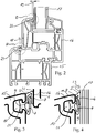
- Fig. 2 is a cross section of a window with frame 15 and sash 16 shown in cross section.
- the gap 18 between the frame and sash is 3.5 mm, while the gap 19 between the glazing 17 and the outer flashover of the sash 16 is 2.5 mm.
- Fig. 3 is the detail "A” according to Fig. 2 and in Fig. 4 the detail "B” according to Fig. 2 each shown enlarged.
- the sealing area 6 presses on the severely bent web 7, while the support cam 4 also presses on the web 7 from the opposite side.
- the kink 8 is quasi positively clamped between the bottom of the sealing region 6 and the support cam 4.
- shear stress as occurs in particular on the hinge side of the window reliably prevents carding of the seal, that is, that the seal with its sealing region 6 relative to the casement 16 slides rather than that the seal 1 would be deformed unevenly by the shear stress.
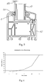
- Fig. 6 In the diagram according to Fig. 6 are the typical contact forces on the compression specified. With a gap of 3.5 mm, as in Fig. 3 is shown, the closing force is about 18 N / 10 cm, while when using the same seal as glazing gasket with a gap of 2.5 mm, the glazing pressure determining pressure force is about 65 N / 10 cm.
- the same seal geometry can be used both as a glazing gasket and as an abutment seal, wherein the gap when using as a glazing gasket with typically 2.5 mm substantially lower is than when used as a stop seal with typically 3.5 mm.
- the seal 1 when used as a stop seal, the seal 1 while only compressed so far that the web 7 either does not touch the support cam 4 or only small supporting forces, while the seal 1 when used as a glazing gasket is at least as far compressed that the web 7 on the support cam 4 supports and this bends towards the inside 14, whereby the glazing pressure is considerably higher than the contact pressure when used as a stop seal.
Landscapes
- Engineering & Computer Science (AREA)
- Civil Engineering (AREA)
- Structural Engineering (AREA)
- Specific Sealing Or Ventilating Devices For Doors And Windows (AREA)
Description
- Die Erfindung betrifft die Verwendung einer Dichtung als Anschlag- oder Verglasungsdichtung eines Fensters, insbesondere als anextrudierte Dichtung, sowie ein Profilsystem mit wenigstens einer Anschlagdichtung und einer Verglasungsdichtung, und die Verwendung eines solchen Profilsystems zur Herstellung eines Fensters. Fenster- und Türprofile aus thermoplastischem Kunststoff weisen grundsätzlich eine Vielzahl von Dichtungen auf, bei denen man insbesondere Anschlagdichtungen und Verglasungsdichtungen unterscheidet. Verglasungsdichtungen liegen sichtbar zwischen der Füllung - in der Regel einer Isolierglasscheibe - und dem Flügelrahmen bzw. bei Festverglasungen dem Blendrahmen, während Anschlagdichtungen den Spalt zwischen dem Blendrahmen und dem Flügelrahmen auf der Außenseite und der Innenseite des Fensters abdichten. Beide Dichtungsarten müssen neben der Dichtfunktion Toleranzen im Spaltmaß aufnehmen und bei der Anschlagdichtung möglichst geringe, bei der Verglasungsdichtung relativ hohe Anpressdrücke erzeugen.
- Neben weichelastischen Dichtungen, die mit einem entsprechend geformten Fuß in Dichtungsnuten des Blend- bzw. Flügelrahmens eingerollt bzw. eingedrückt werden, werden zunehmend anextrudierte Dichtungen aus weichelastischem, thermoplastischem Material verwendet, wobei üblicherweise das sogenannte Post-Coextrusionsverfahren (PCE) eingesetzt wird. Nach diesem Verfahren werden sowohl die Anschlagdichtungen als auch die Verglasungsdichtungen inline auf die extrudierten, bereits kalibrierten Blendrahmen- und Flügelrahmenprofile anextrudiert. Verglasungsdichtungen und Anschlagdichtungen haben unterschiedliche Anforderungen beim Anpressdruck und im abzudichtenden Spaltmaß. Daher werden häufig unterschiedliche Profilgeometrien für Verglasungsdichtungen und Anschlagdichtungen eingesetzt. In bestimmten Anwendungsfällen wird jedoch eine Dichtung, die üblicherweise als Anschlagdichtung verwendet wird, als Verglasungsdichtung eingesetzt, beispielsweise bei Festverglasungen in einem Blendrahmen. Es besteht daher ein Bedürfnis, Universaldichtungen einzusetzen, die sowohl als Anschlagdichtung als auch als Verglasungsdichtung eingesetzt werden können.
- Aus der
DE 197 20 940 B4 ist eine anextrudierte Dichtung bekannt, die mit identischer Geometrie sowohl als Anschlagdichtung als auch als Verglasungsdichtung eingesetzt werden kann. Die dort gezeigte Dichtungsgeometrie hat sich zwar in der Praxis weitgehend bewährt, allerdings neigt diese Dichtung beim Einsatz als Verglasungsdichtung sowie beim Einsatz als Anschlagdichtung an der Bandseite zum Krempeln oder Einrollen, d. h., die Dichtung wird bei gleichzeitiger Druck- und Scherbeanspruchung ungleichmäßig, zum Teil wellenförmig deformiert. - Aus der
GB 2 352 262 A1 - Aus der
DE 10 2005 044 420 B3 ist eine Dichtung zum Einsatz als Anschlagdichtung für stumpf eindrehende und überfalzte Flügelrahmen bekannt. Diese Dichtung kann jedoch aufgrund ihrer Geometrie nicht als Verglasungsdichtung verwendet werden. - Aufgabe der vorliegenden Erfindung ist es, eine insbesondere anextrudierte Dichtung für Fenster zur Verfügung zu stellen, die sowohl als Anschlagdichtung als auch als Verglasungsdichtung eingesetzt werden kann und diese Nachteile nicht aufweist.
- Die Erfindung löst diese Aufgabe mit einer Dichtung, die einen Dichtungsfuß und einen eine Hohlkammer aufweisenden Dichtungskopf aufweist, wobei der Dichtungskopf einen zur Außenseite geneigten und/oder gebogenen Sichtbereich, einen Dichtbereich sowie einen den Dichtbereich stützenden Steg - nachfolgend auch Stützsteg genannt - aufweist. Die Dichtung weist erfindungsgemäß einen zur Innenseite geneigten Stütznocken in der Hohlkammer auf. Die Dichtung kann als Universaldichtung sowohl als Anschlagdichtung als auch als Verglasungsdichtung eingesetzt werden, wobei bevorzugt beim Einsatz als Anschlagdichtung das Spaltmaß zwischen Blendrahmen und Flügelrahmen 3 bis 4 mm und beim Einsatz als Verglasungsdichtung das Spaltmaß 0,7 bis 1,5 mm geringer gewählt wird.
- Als Außenseite der Dichtung wird die bei geschlossenem Fenster von außen sichtbare Kante der Dichtung bezeichnet, während die Innenseite der Dichtung bei einer Verglasungsdichtung nicht und bei einer Anschlagdichtung nur bei geöffnetem Fenster sichtbar ist.
- Bevorzugt ist der Sichtbereich der Dichtung leicht sichelförmig zur Außenseite gebogen und mündet bevorzugt annähernd im rechten Winkel - mit einer abgerundeten Kante mit geringem Radius - in den Dichtbereich, der bevorzugt zumindest annähernd eben gestaltet ist.
- Der Stützsteg mündet bevorzugt etwa in der Mitte des Dichtbereichs in diesen und weist bevorzugt in unmittelbarer Nähe dieses Mündungsbereichs einen Knick auf. Beim bestimmungsgemäßen Stauchen der Dichtung, also insbesondere beim Verglasen eines Flügels im Falle einer Verglasungsdichtung und beim Schließen des Flügels im Falle einer Anschlagdichtung, wird der sichelförmig zur Außenseite gebogene Sichtbereich weiter zur Außenseite tordiert und der Stützsteg im Knickbereich ebenfalls zur Außenseite geknickt, so dass sich die Dichtung insgesamt ähnlich einer Faltung zusammenlegt und dabei leicht in Richtung zur Außenseite gedrückt wird.
- Der erfindungsgemäße, leicht zur Innenseite geneigte Stütznocken in der Hohlkammer der Dichtung erfüllt dabei eine doppelte Aufgabe: Beim Einsatz der Dichtung als Verglasungsdichtung drückt bzw. biegt der Stützsteg diesen Stütznocken in Richtung zum Dichtungsfuß, wodurch der Verglasungsdruck stark ansteigt. Sowohl beim Einsatz als Verglasungsdichtung als auch beim Einsatz als Anschlagdichtung legt sich der Knick des stützenden Stegs quasi formschlüssig hinter den Stütznocken und erhöht dadurch die Schersteifigkeit der gestauchten Dichtung. Durch diese erhöhte Schersteifigkeit der Dichtung im gestauchten Zustand gleitet die Dichtung mit dem Dichtbereich eher an der Anlagefläche - beim Einsatz als Verglasungsdichtung also an der Verglasung und beim Einsatz als Anschlagdichtung am angrenzenden Profil - als dass sich die Dichtung im Sichtbereich krempelt oder einrollt.
- Die erfindungsgemäße Dichtung kann durch entsprechende Dimensionierung des Stütznockens so ausgelegt werden, dass sie eine annähernd exponentielle Stauch/Druck-Charakteristik aufweist, d. h., dass bei geringen Stauchungen, wie sie im Anschlagdichtungsbereich üblich sind, die von der Dichtung auf den angrenzenden Rahmen ausgeübte Kraft sehr gering ist, bevorzugt im Bereich < 30 N je 100 mm Dichtungslänge, während bei größeren Stauchungen, wie sie im Verglasungsdichtungsbereich üblich sind, die von der Dichtung auf die angrenzende Füllung ausgeübte Kraft überproportional ansteigt auf bevorzugte Werte im Bereich > 70 N je 100 mm Dichtungslänge.
- Nach einer besonders bevorzugten Ausführungsform der Erfindung wird die erfindungsgemäße Dichtung im an sich bekannten PCE-Verfahren an ein Blend- und/oder Flügelrahmenprofil anextrudiert, wobei bevorzugt nur die vom Dichtungsfuß zur Außenseite der Dichtung verlaufende am Rahmenprofil angrenzende Auflagefläche der Dichtung mit dem Rahmenprofil verschweißt bzw. stoffschlüssig verbunden ist. Ggf. können auch Teilbereiche des Dichtungsfußes mit dem Rahmenprofil verschweißt sein, während der innenseitige Bereich der Dichtung bevorzugt nicht mit dem Rahmenprofil stoffschlüssig verbunden ist, um eine Relativbewegung zwischen Dichtung und umgebendem Rahmenbereich bei der bestimmungsgemäßen Stauchung der Dichtung zu ermöglichen.
- Bevorzugt wird die Dichtung aus thermoplastischem Elastomer oder Weich-PVC (PVC-P) hergestellt, insbesondere homogen aus nur einer Komponente.
- Die Erfindung wird nachfolgend anhand eines Ausführungsbeispiels sowie der Zeichnung näher erläutert. Es zeigen dabei:
- Fig. 1
- einen stark vergrößerten Querschnitt der erfindungsgemäßen Dichtung;
- Fig. 2
- einen Querschnitt eines Fensters mit erfindungsgemäßer Anschlag- und Verglasungsdichtung;
- Fig. 3
- Detail "A" gemäß
Fig. 2 ; - Fig. 4
- Detail "B" gemäß
Fig. 2 ; - Fig. 5
- einen Querschnitt eines Fensters mit Festverglasung;
- Fig. 6
- ein Druck/Stauchdiagramm.
- Die erfindungsgemäße Dichtung 1 weist als wesentliche Elemente einen Dichtungsfuß 12 sowie einen Dichtungskopf 2 auf, der als Hohlkammerprofil mit der Hohlkammer 3 ausgebildet ist. Die Dichtung 1 weist - im Querschnitt betrachtet - vom Dichtungsfuß 12 ausgehend zunächst eine Auflagefläche 11 auf, die annähernd im rechten Winkel an der Außenseite 13 in den leicht sichelförmig nach außen gebogenen Sichtbereich 5 übergeht. Auf der Oberseite schließt sich der Dichtbereich 6 an, von dem etwa mittig der Steg 7 abspringt und die Verbindung zwischen Dichtbereich 6 und Dichtungsfuß 12 bildet. Der Steg 7 mündet etwa im rechten Winkel in den Sichtbereich 5 und bildet mit diesem eine T-Form, wobei der Steg 7 nahe dem Sichtbereich 5 an der Knickstelle 8 in Richtung zur Innenseite 14 abknickt.
- Wie in
Fig. 1 zu erkennen ist, ist der Sichtbereich 5 leicht sichelförmig zur Außenseite 13 gebogen und geht über die abgerundete Spitze 22 annähernd im rechten Winkel in den Dichtbereich 6 über, wobei dieser im unbelasteten Zustand im spitzen Winkel zur Profiloberfläche bzw. Auflagefläche 11 - zur Außenseite 13 geneigt - verläuft. - Am Übergang zwischen der Auflagefläche 11 und dem Fußbereich 12 ragt der erfindungswesentliche Stütznocken 4 - mit leichter Neigung in Richtung zur Innenseite 14 gerichtet - in die Hohlkammer 3.
- Die Dichtung 1 ist in an sich bekannter Weise im Post-Coextrusionsverfahren (PCE-Verfahren) aus Weich-PVC (PVC-P) an das Profil 9 aus Hart-PVC (PVC-U) anextrudiert, wobei ausschließlich die Auflagefläche 11 und Teile des Fußbereichs 12 mit den Kontaktflächen des Profils 9 stoffschlüssig verbunden sind. Insbesondere der Übergang vom Stützsteg 7 zum Fußbereich 12 einschließlich des gesamten etwa im Winkel von 45° zurückspringenden Bereichs des Steges 7 ist jedoch nicht mit dem Profil 9 verschweißt.
- In
Fig. 2 ist ein Querschnitt eines Fensters mit Blendrahmen 15 und Flügelrahmen 16 im Querschnitt dargestellt. Das Spaltmaß 18 zwischen Blendrahmen und Flügelrahmen beträgt 3,5 mm, während das Spaltmaß 19 zwischen der Verglasung 17 und dem äußeren Überschlag des Flügelrahmens 16 2,5 mm beträgt. - In
Fig. 3 ist das Detail "A" gemäßFig. 2 und inFig. 4 das Detail "B" gemäßFig. 2 jeweils vergrößert dargestellt. Man erkennt, dass beim Einsatz als Verglasungsdichtung 20 gemäßFig. 4 bei einem Spaltmaß von 2,5 mm der Dichtbereich 6 auf den stark abgeknickten Steg 7 presst, während von der Gegenseite der Stütznocken 4 ebenfalls auf den Steg 7 drückt. Der Knick 8 wird dabei quasi formschlüssig zwischen der Unterseite des Dichtbereiches 6 und dem Stütznocken 4 eingeklemmt. Durch dieses gezielte Falten der Dichtung 1 ergeben sich einerseits relativ hohe Verglasungsdrücke, andererseits wird ein Krempeln oder Einrollen der Dichtung 1 bei Scherbeanspruchung zuverlässig vermieden. Die Dichtung 1 gleitet vielmehr bei Scherbeanspruchung mit ihrem Dichtbereich 6 auf der Verglasung 17, so dass die Spitze 22 weiterhin zur Außenseite 13 zeigt. - Im Vergleich dazu wird die erfindungsgemäße Dichtung 1 beim Einsatz als Anschlagdichtung 21 bei einem Spaltmaß von 3,5 mm, wie es in
Fig. 3 vergrößert dargestellt ist, wesentlich weniger gestaucht, so dass die Schließkräfte des Fensters relativ gering bleiben. Der Knick 8 wird aber auch in diesem Fall quasi formschlüssig zwischen der Unterseite des Dichtbereiches 6 und dem Stütznocken 4 eingeklemmt. So wird auch beim Einsatz der erfindungsgemäßen Dichtung 1 als Anschlagdichtung 21 gemäßFig. 3 bei Scherbeanspruchung, wie sie insbesondere an der Bandseite des Fensters auftritt, zuverlässig ein Krempeln der Dichtung verhindert, d. h., dass die Dichtung mit ihrem Dichtbereich 6 gegenüber dem Flügelrahmen 16 eher gleitet, als dass die Dichtung 1 durch die Scherbeanspruchung ungleichmäßig verformt würde. - Im Diagramm gemäß
Fig. 6 sind die typischen Anpresskräfte über die Stauchung angegeben. Bei einem Spaltmaß von 3,5 mm, wie es inFig. 3 dargestellt ist, beträgt die Schließkraft etwa 18 N/10 cm, während beim Einsatz derselben Dichtung als Verglasungsdichtung mit einem Spaltmaß von 2,5 mm die den Verglasungsdruck bestimmende Andruckkraft ca. 65 N/10 cm beträgt. - Neben dem Vermeiden von Krempeln oder Einrollen der Dichtung 1 bei Scherbeanspruchung ist es ein wichtiger Vorteil der erfindungsgemäßen Dichtung, dass dieselbe Dichtungsgeometrie sowohl als Verglasungsdichtung als auch als Anschlagdichtung eingesetzt werden kann, wobei das Spaltmaß beim Einsatz als Verglasungsdichtung mit typisch 2,5 mm wesentlich geringer ist als beim Einsatz als Anschlagdichtung mit typisch 3,5 mm. Beim Einsatz als Anschlagdichtung wird die Dichtung 1 dabei lediglich soweit gestaucht, dass der Steg 7 den Stütznocken 4 entweder nicht berührt oder nur geringe Stützkräfte ausübt, während die Dichtung 1 beim Einsatz als Verglasungsdichtung zumindest soweit gestaucht wird, dass der Steg 7 sich auf dem Stütznocken 4 abstützt und diesen in Richtung zur Innenseite 14 biegt, wodurch der Verglasungsdruck erheblich höher liegt als der Anpressdruck beim Einsatz als Anschlagdichtung.
-
- 1
- Dichtung
- 2
- Dichtungskopf
- 3
- Hohlkammer
- 4
- Stütznocken
- 5
- Sichtbereich
- 6
- Dichtbereich
- 7
- Steg (Stützsteg)
- 8
- Knick
- 9
- Profil
- 10
- Dichtungsaufnahmenut
- 11
- Auflagefläche
- 12
- Dichtungsfuß
- 13
- Außenseite
- 14
- Innenseite
- 15
- Blendrahmen
- 16
- Flügelrahmen
- 17
- Verglasung
- 18
- Spaltmaß
- 19
- Spaltmaß
- 20
- Verglasungsdichtung
- 21
- Anschlagdichtung
- 22
- Spitze
Claims (9)
- Verwendung einer Dichtung (1) als Anschlag- oder Verglasungsdichtung eines Fensters,- wobei die Dichtung (1) eine Außenseite (13), eine Innenseite (14), einen Dichtungsfuß (12), einen eine Hohlkammer (3) aufweisenden Dichtungskopf (2) und eine Auflagefläche (11) aufweist,- wobei der Dichtungskopf (2) einen zur Außenseite (13) geneigten und/oder gebogenen Sichtbereich (5), einen Dichtbereich (6) sowie einen den Dichtbereich (6) stützenden Steg (7) aufweist, und- wobei die Dichtung (1) einen Stütznocken (4) in der Hohlkammer (3) aufweist,dadurch gekennzeichnet, dass der Stütznocken (4) am Übergang zwischen dem Dichtungsfuß (12) und der Auflagefläche (11) der Dichtung (1) angeordnet ist und zur Innenseite (14) geneigt ist.
- Verwendung nach Anspruch 1, dadurch gekennzeichnet, dass der stützende Steg (7) in unmittelbarer Nähe des Dichtbereichs (6) einen Knick (8) aufweist.
- Verwendung nach einem der Ansprüche 1 oder 2, dadurch gekennzeichnet, dass der Sichtbereich (5) leicht sichelförmig zur Außenseite (13) gebogen ist.
- Verwendung nach einem der Ansprüche 1 bis 3, dadurch gekennzeichnet, dass die Dichtung (1) im PCE-Verfahren anextrudiert wurde.
- Verwendung einer im PCE-Verfahren anextrudierten Dichtung (1) nach Anspruch 4 als Anschlagdichtung.
- Verwendung einer im PCE-Verfahren anextrudierten Dichtung (1) nach Anspruch 4 als Verglasungsdichtung.
- Profilsystem mit wenigstens einem Blendrahmenprofil (15), wenigstens einem Flügelrahmenprofil (16), wenigstens einer Anschlagdichtung (21) und wenigstens eine Verglasungsdichtung (20),- wobei wenigstens eine Anschlagdichtung (21) und wenigstens eine Verglasungsdichtung (20) die gleiche Querschnittsform mit einer Außenseite (13) und einer Innenseite (14) aufweisen,- wobei die Anschlagdichtung (21) und die Verglasungsdichtung (20) je eine Außenseite (13), eine Innenseite (14), einen Dichtungsfuß (12), einen eine Hohlkammer (3) aufweisenden Dichtungskopf (2) und eine Auflagefläche (11) aufweisen,- wobei der Dichtungskopf (2) einen zur Außenseite (13) geneigten und/oder gebogenen Sichtbereich (5), einen Dichtbereich (6) sowie einen den Dichtbereich (6) stützenden Steg (7)aufweist, und- wobei die Anschlagdichtung (21) und die Verglasungsdichtung (20) je einen Stütznocken (4) in der Hohlkammer (3) aufweisen,dadurch gekennzeichnet, dass die Stütznocken (4) der Anschlagdichtung (21) und der Verglasungsdichtung (20) am Übergang zwischen dem Dichtungsfuß (12) und der Auflagefläche (11) der Dichtung (1) angeordnet und zur Innenseite (14) geneigt sind.
- Profilsystem nach Anspruch 7, dadurch gekennzeichnet, dass wenigstens eine Anschlagdichtung (21) und wenigstens eine Verglasungsdichtung (20) im PCE-Verfahren anextrudiert wurden.
- Verwendung eines Profilsystems nach Anspruch 7 oder 8 zur Herstellung eines Fensters mit einem Blendrahmen (15), wenigstens einem Flügelrahmen (16) und wenigstens einer Füllung im Flügelrahmen (16), wobei das Spaltmaß (18) zwischen Blend- und Flügelrahmen 0,5 bis 1,5 mm größer ist als das Spaltmaß (19) zwischen Füllung und Flügelrahmen (16).
Priority Applications (1)
| Application Number | Priority Date | Filing Date | Title |
|---|---|---|---|
| PL09713283T PL2265790T3 (pl) | 2008-02-20 | 2009-02-19 | Uszczelka do profili okiennych lub drzwiowych |
Applications Claiming Priority (2)
| Application Number | Priority Date | Filing Date | Title |
|---|---|---|---|
| DE102008000358 | 2008-02-20 | ||
| PCT/EP2009/051962 WO2009103756A1 (de) | 2008-02-20 | 2009-02-19 | Dichtung für fenster- oder türprofile |
Publications (2)
| Publication Number | Publication Date |
|---|---|
| EP2265790A1 EP2265790A1 (de) | 2010-12-29 |
| EP2265790B1 true EP2265790B1 (de) | 2017-07-19 |
Family
ID=40547373
Family Applications (1)
| Application Number | Title | Priority Date | Filing Date |
|---|---|---|---|
| EP09713283.1A Active EP2265790B1 (de) | 2008-02-20 | 2009-02-19 | Dichtung für fenster- oder türprofile |
Country Status (4)
| Country | Link |
|---|---|
| EP (1) | EP2265790B1 (de) |
| DE (1) | DE102009001017A1 (de) |
| PL (1) | PL2265790T3 (de) |
| WO (1) | WO2009103756A1 (de) |
Cited By (6)
| Publication number | Priority date | Publication date | Assignee | Title |
|---|---|---|---|---|
| DE202017107394U1 (de) | 2017-12-05 | 2019-03-06 | Rehau Ag + Co | Dichtung für ein Fenster sowie deren Verwendung |
| DE202017107750U1 (de) | 2017-12-20 | 2019-03-21 | Rehau Ag + Co | Fenster- oder Türprofil |
| DE202017107749U1 (de) | 2017-12-20 | 2019-03-21 | Rehau Ag + Co | Fenster- oder Türprofil |
| EP4053373A1 (de) | 2021-03-01 | 2022-09-07 | ASSA ABLOY (Schweiz) AG | Dichtung für schiebetüren und -fenster |
| DE202021004242U1 (de) | 2021-03-01 | 2023-03-21 | Assa Abloy (Schweiz) Ag | Dichtung für Schiebetüren |
| EP4421280A1 (de) | 2023-02-24 | 2024-08-28 | profine GmbH | Verbundrahmen für ein fenster oder eine tür |
Families Citing this family (6)
| Publication number | Priority date | Publication date | Assignee | Title |
|---|---|---|---|---|
| DE202011000265U1 (de) | 2010-04-13 | 2011-06-09 | Lindner, Lutz, 08321 | Bauelement zum Verschluss von Wandöffnungen |
| DE202011106521U1 (de) | 2011-10-10 | 2011-12-21 | Rundum Dicht Krystyna Doll Kg | Multifunktionsdichtung für Fenster und Türen |
| DE202012007885U1 (de) | 2012-08-20 | 2012-10-25 | Rundum Dicht Krystyna Doll Kg | Quadrodichtung für Holzfenster und Holztüren mit Nut |
| DE202014101413U1 (de) * | 2014-03-26 | 2015-06-29 | Rehau Ag + Co. | Fenster- oder Tür-Kunststoffprofil |
| US10734320B2 (en) | 2018-07-30 | 2020-08-04 | Infineon Technologies Austria Ag | Power metallization structure for semiconductor devices |
| US12196036B2 (en) | 2022-02-03 | 2025-01-14 | Jeld-Wen, Inc. | Wet glazing shield gasket for fenestration unit |
Family Cites Families (4)
| Publication number | Priority date | Publication date | Assignee | Title |
|---|---|---|---|---|
| DE3329086C1 (de) * | 1983-08-11 | 1984-10-25 | Bosch-Siemens Hausgeräte GmbH, 7000 Stuttgart | Dichtungsprofil |
| DE19720940B4 (de) | 1997-05-20 | 2006-05-11 | Profine Gmbh | Fenster- oder Türprofil mit anextrudierter Dichtung |
| GB9913959D0 (en) * | 1999-06-15 | 1999-08-18 | Epwin Group Plc | Seals |
| DE102005044420B3 (de) * | 2005-09-16 | 2007-02-15 | Deventer Profile Gmbh & Co. Kg | Elastisches Strangdichtungsprofil für Fenster, Türen oder dgl. |
-
2009
- 2009-02-19 EP EP09713283.1A patent/EP2265790B1/de active Active
- 2009-02-19 PL PL09713283T patent/PL2265790T3/pl unknown
- 2009-02-19 DE DE102009001017A patent/DE102009001017A1/de not_active Withdrawn
- 2009-02-19 WO PCT/EP2009/051962 patent/WO2009103756A1/de not_active Ceased
Non-Patent Citations (1)
| Title |
|---|
| None * |
Cited By (7)
| Publication number | Priority date | Publication date | Assignee | Title |
|---|---|---|---|---|
| DE202017107394U1 (de) | 2017-12-05 | 2019-03-06 | Rehau Ag + Co | Dichtung für ein Fenster sowie deren Verwendung |
| DE202017107750U1 (de) | 2017-12-20 | 2019-03-21 | Rehau Ag + Co | Fenster- oder Türprofil |
| DE202017107749U1 (de) | 2017-12-20 | 2019-03-21 | Rehau Ag + Co | Fenster- oder Türprofil |
| EP4053373A1 (de) | 2021-03-01 | 2022-09-07 | ASSA ABLOY (Schweiz) AG | Dichtung für schiebetüren und -fenster |
| DE202021004242U1 (de) | 2021-03-01 | 2023-03-21 | Assa Abloy (Schweiz) Ag | Dichtung für Schiebetüren |
| EP4421280A1 (de) | 2023-02-24 | 2024-08-28 | profine GmbH | Verbundrahmen für ein fenster oder eine tür |
| DE102023104515A1 (de) | 2023-02-24 | 2024-08-29 | Profine Gmbh | Verbundrahmen für ein Fenster oder eine Tür |
Also Published As
| Publication number | Publication date |
|---|---|
| EP2265790A1 (de) | 2010-12-29 |
| WO2009103756A1 (de) | 2009-08-27 |
| PL2265790T3 (pl) | 2017-12-29 |
| DE102009001017A1 (de) | 2009-08-27 |
Similar Documents
| Publication | Publication Date | Title |
|---|---|---|
| EP2265790A1 (de) | Dichtung für fenster- oder türprofile | |
| DE19510597B4 (de) | Allround-Dichtungsprofil | |
| EP1987220B1 (de) | Gerahmtes flächentragelement sowie rahmenprofil für ein derartiges gerahmtes flächentragelement | |
| DE202017104445U1 (de) | Fenster oder Tür mit Dichtung für Flügel | |
| DE2820620A1 (de) | Elastische dicht- und befestigungsleiste, insbesondere fuer scheiben in kraftfahrzeugkarosserien | |
| DE102008046753B4 (de) | Elastische Strangdichtung für Fenster, Türen oder dgl. | |
| EP2603658A1 (de) | Fenster | |
| EP2363567B1 (de) | Rahmen eines Kunststofffensters oder einer Kunststofftür | |
| DE29722564U1 (de) | Dichtungsprofil für Fenster oder Türen | |
| EP3216967B1 (de) | Dichtungsprofil für fenster, türen oder fassaden | |
| DE202023105492U1 (de) | Strangdichtung | |
| EP3495599B1 (de) | Dichtung für ein fenster sowie deren verwendung | |
| EP1009902B1 (de) | Strangförmige dichtung | |
| DE102012106614B4 (de) | Steckdichtungsprofil und Steckdichtungsanordnung mit einem solchen Steckdichtungsprofil | |
| DE102013204944B4 (de) | Elastische Strangdichtung für Fenster, Türen oder dgl. | |
| AT409524B (de) | Profildichtung | |
| DE29814787U1 (de) | Strangförmige Verglasungsdichtung | |
| EP3502403B1 (de) | Fenster- oder türprofil | |
| DE8418539U1 (de) | Strangfoermige fluegelfalzdichtung aus kunststoff fuer fenster, tueren oder dgl. | |
| DE9402689U1 (de) | Anschlagdichtung | |
| EP4375473B1 (de) | Verbesserte dichtleiste und tür oder fenster mit verbesserter dichtleiste | |
| DE202020105995U1 (de) | Strangdichtung aus elastischem Schaummaterial | |
| EP3502404A1 (de) | Fenster- oder türprofil | |
| AT11890U1 (de) | Fensterelement | |
| EP3168407A1 (de) | Steckdichtung und steckdichtungsanordnung |
Legal Events
| Date | Code | Title | Description |
|---|---|---|---|
| PUAI | Public reference made under article 153(3) epc to a published international application that has entered the european phase |
Free format text: ORIGINAL CODE: 0009012 |
|
| 17P | Request for examination filed |
Effective date: 20100920 |
|
| AK | Designated contracting states |
Kind code of ref document: A1 Designated state(s): AT BE BG CH CY CZ DE DK EE ES FI FR GB GR HR HU IE IS IT LI LT LU LV MC MK MT NL NO PL PT RO SE SI SK TR |
|
| AX | Request for extension of the european patent |
Extension state: AL BA RS |
|
| RAP1 | Party data changed (applicant data changed or rights of an application transferred) |
Owner name: PROFINE GMBH |
|
| DAX | Request for extension of the european patent (deleted) | ||
| 17Q | First examination report despatched |
Effective date: 20160415 |
|
| GRAP | Despatch of communication of intention to grant a patent |
Free format text: ORIGINAL CODE: EPIDOSNIGR1 |
|
| STAA | Information on the status of an ep patent application or granted ep patent |
Free format text: STATUS: GRANT OF PATENT IS INTENDED |
|
| INTG | Intention to grant announced |
Effective date: 20170209 |
|
| GRAS | Grant fee paid |
Free format text: ORIGINAL CODE: EPIDOSNIGR3 |
|
| GRAJ | Information related to disapproval of communication of intention to grant by the applicant or resumption of examination proceedings by the epo deleted |
Free format text: ORIGINAL CODE: EPIDOSDIGR1 |
|
| GRAL | Information related to payment of fee for publishing/printing deleted |
Free format text: ORIGINAL CODE: EPIDOSDIGR3 |
|
| STAA | Information on the status of an ep patent application or granted ep patent |
Free format text: STATUS: EXAMINATION IS IN PROGRESS |
|
| GRAR | Information related to intention to grant a patent recorded |
Free format text: ORIGINAL CODE: EPIDOSNIGR71 |
|
| STAA | Information on the status of an ep patent application or granted ep patent |
Free format text: STATUS: GRANT OF PATENT IS INTENDED |
|
| GRAA | (expected) grant |
Free format text: ORIGINAL CODE: 0009210 |
|
| STAA | Information on the status of an ep patent application or granted ep patent |
Free format text: STATUS: THE PATENT HAS BEEN GRANTED |
|
| INTC | Intention to grant announced (deleted) | ||
| INTG | Intention to grant announced |
Effective date: 20170608 |
|
| AK | Designated contracting states |
Kind code of ref document: B1 Designated state(s): AT BE BG CH CY CZ DE DK EE ES FI FR GB GR HR HU IE IS IT LI LT LU LV MC MK MT NL NO PL PT RO SE SI SK TR |
|
| REG | Reference to a national code |
Ref country code: GB Ref legal event code: FG4D Free format text: NOT ENGLISH |
|
| REG | Reference to a national code |
Ref country code: CH Ref legal event code: EP |
|
| REG | Reference to a national code |
Ref country code: IE Ref legal event code: FG4D Free format text: LANGUAGE OF EP DOCUMENT: GERMAN |
|
| REG | Reference to a national code |
Ref country code: AT Ref legal event code: REF Ref document number: 910573 Country of ref document: AT Kind code of ref document: T Effective date: 20170815 |
|
| REG | Reference to a national code |
Ref country code: DE Ref legal event code: R096 Ref document number: 502009014171 Country of ref document: DE |
|
| REG | Reference to a national code |
Ref country code: NL Ref legal event code: MP Effective date: 20170719 |
|
| REG | Reference to a national code |
Ref country code: LT Ref legal event code: MG4D |
|
| PG25 | Lapsed in a contracting state [announced via postgrant information from national office to epo] |
Ref country code: FI Free format text: LAPSE BECAUSE OF FAILURE TO SUBMIT A TRANSLATION OF THE DESCRIPTION OR TO PAY THE FEE WITHIN THE PRESCRIBED TIME-LIMIT Effective date: 20170719 Ref country code: SE Free format text: LAPSE BECAUSE OF FAILURE TO SUBMIT A TRANSLATION OF THE DESCRIPTION OR TO PAY THE FEE WITHIN THE PRESCRIBED TIME-LIMIT Effective date: 20170719 Ref country code: HR Free format text: LAPSE BECAUSE OF FAILURE TO SUBMIT A TRANSLATION OF THE DESCRIPTION OR TO PAY THE FEE WITHIN THE PRESCRIBED TIME-LIMIT Effective date: 20170719 Ref country code: LT Free format text: LAPSE BECAUSE OF FAILURE TO SUBMIT A TRANSLATION OF THE DESCRIPTION OR TO PAY THE FEE WITHIN THE PRESCRIBED TIME-LIMIT Effective date: 20170719 Ref country code: NO Free format text: LAPSE BECAUSE OF FAILURE TO SUBMIT A TRANSLATION OF THE DESCRIPTION OR TO PAY THE FEE WITHIN THE PRESCRIBED TIME-LIMIT Effective date: 20171019 Ref country code: NL Free format text: LAPSE BECAUSE OF FAILURE TO SUBMIT A TRANSLATION OF THE DESCRIPTION OR TO PAY THE FEE WITHIN THE PRESCRIBED TIME-LIMIT Effective date: 20170719 |
|
| REG | Reference to a national code |
Ref country code: FR Ref legal event code: PLFP Year of fee payment: 10 |
|
| PG25 | Lapsed in a contracting state [announced via postgrant information from national office to epo] |
Ref country code: BG Free format text: LAPSE BECAUSE OF FAILURE TO SUBMIT A TRANSLATION OF THE DESCRIPTION OR TO PAY THE FEE WITHIN THE PRESCRIBED TIME-LIMIT Effective date: 20171019 Ref country code: ES Free format text: LAPSE BECAUSE OF FAILURE TO SUBMIT A TRANSLATION OF THE DESCRIPTION OR TO PAY THE FEE WITHIN THE PRESCRIBED TIME-LIMIT Effective date: 20170719 Ref country code: IS Free format text: LAPSE BECAUSE OF FAILURE TO SUBMIT A TRANSLATION OF THE DESCRIPTION OR TO PAY THE FEE WITHIN THE PRESCRIBED TIME-LIMIT Effective date: 20171119 Ref country code: LV Free format text: LAPSE BECAUSE OF FAILURE TO SUBMIT A TRANSLATION OF THE DESCRIPTION OR TO PAY THE FEE WITHIN THE PRESCRIBED TIME-LIMIT Effective date: 20170719 Ref country code: GR Free format text: LAPSE BECAUSE OF FAILURE TO SUBMIT A TRANSLATION OF THE DESCRIPTION OR TO PAY THE FEE WITHIN THE PRESCRIBED TIME-LIMIT Effective date: 20171020 |
|
| REG | Reference to a national code |
Ref country code: DE Ref legal event code: R097 Ref document number: 502009014171 Country of ref document: DE |
|
| PG25 | Lapsed in a contracting state [announced via postgrant information from national office to epo] |
Ref country code: CZ Free format text: LAPSE BECAUSE OF FAILURE TO SUBMIT A TRANSLATION OF THE DESCRIPTION OR TO PAY THE FEE WITHIN THE PRESCRIBED TIME-LIMIT Effective date: 20170719 Ref country code: RO Free format text: LAPSE BECAUSE OF FAILURE TO SUBMIT A TRANSLATION OF THE DESCRIPTION OR TO PAY THE FEE WITHIN THE PRESCRIBED TIME-LIMIT Effective date: 20170719 Ref country code: DK Free format text: LAPSE BECAUSE OF FAILURE TO SUBMIT A TRANSLATION OF THE DESCRIPTION OR TO PAY THE FEE WITHIN THE PRESCRIBED TIME-LIMIT Effective date: 20170719 |
|
| PLBE | No opposition filed within time limit |
Free format text: ORIGINAL CODE: 0009261 |
|
| STAA | Information on the status of an ep patent application or granted ep patent |
Free format text: STATUS: NO OPPOSITION FILED WITHIN TIME LIMIT |
|
| PG25 | Lapsed in a contracting state [announced via postgrant information from national office to epo] |
Ref country code: IT Free format text: LAPSE BECAUSE OF FAILURE TO SUBMIT A TRANSLATION OF THE DESCRIPTION OR TO PAY THE FEE WITHIN THE PRESCRIBED TIME-LIMIT Effective date: 20170719 Ref country code: EE Free format text: LAPSE BECAUSE OF FAILURE TO SUBMIT A TRANSLATION OF THE DESCRIPTION OR TO PAY THE FEE WITHIN THE PRESCRIBED TIME-LIMIT Effective date: 20170719 Ref country code: SK Free format text: LAPSE BECAUSE OF FAILURE TO SUBMIT A TRANSLATION OF THE DESCRIPTION OR TO PAY THE FEE WITHIN THE PRESCRIBED TIME-LIMIT Effective date: 20170719 |
|
| 26N | No opposition filed |
Effective date: 20180420 |
|
| PG25 | Lapsed in a contracting state [announced via postgrant information from national office to epo] |
Ref country code: SI Free format text: LAPSE BECAUSE OF FAILURE TO SUBMIT A TRANSLATION OF THE DESCRIPTION OR TO PAY THE FEE WITHIN THE PRESCRIBED TIME-LIMIT Effective date: 20170719 |
|
| REG | Reference to a national code |
Ref country code: CH Ref legal event code: PL |
|
| PG25 | Lapsed in a contracting state [announced via postgrant information from national office to epo] |
Ref country code: MC Free format text: LAPSE BECAUSE OF FAILURE TO SUBMIT A TRANSLATION OF THE DESCRIPTION OR TO PAY THE FEE WITHIN THE PRESCRIBED TIME-LIMIT Effective date: 20170719 Ref country code: MT Free format text: LAPSE BECAUSE OF FAILURE TO SUBMIT A TRANSLATION OF THE DESCRIPTION OR TO PAY THE FEE WITHIN THE PRESCRIBED TIME-LIMIT Effective date: 20170719 |
|
| REG | Reference to a national code |
Ref country code: IE Ref legal event code: MM4A |
|
| PG25 | Lapsed in a contracting state [announced via postgrant information from national office to epo] |
Ref country code: CH Free format text: LAPSE BECAUSE OF NON-PAYMENT OF DUE FEES Effective date: 20180228 Ref country code: LU Free format text: LAPSE BECAUSE OF NON-PAYMENT OF DUE FEES Effective date: 20180219 Ref country code: LI Free format text: LAPSE BECAUSE OF NON-PAYMENT OF DUE FEES Effective date: 20180228 |
|
| PG25 | Lapsed in a contracting state [announced via postgrant information from national office to epo] |
Ref country code: IE Free format text: LAPSE BECAUSE OF NON-PAYMENT OF DUE FEES Effective date: 20180219 |
|
| REG | Reference to a national code |
Ref country code: AT Ref legal event code: MM01 Ref document number: 910573 Country of ref document: AT Kind code of ref document: T Effective date: 20180219 |
|
| PG25 | Lapsed in a contracting state [announced via postgrant information from national office to epo] |
Ref country code: AT Free format text: LAPSE BECAUSE OF NON-PAYMENT OF DUE FEES Effective date: 20180219 |
|
| REG | Reference to a national code |
Ref country code: DE Ref legal event code: R082 Ref document number: 502009014171 Country of ref document: DE Representative=s name: HOCKER, THOMAS GERHARD, DIPL.-ING., LL.M., DE |
|
| PG25 | Lapsed in a contracting state [announced via postgrant information from national office to epo] |
Ref country code: TR Free format text: LAPSE BECAUSE OF FAILURE TO SUBMIT A TRANSLATION OF THE DESCRIPTION OR TO PAY THE FEE WITHIN THE PRESCRIBED TIME-LIMIT Effective date: 20170719 |
|
| PG25 | Lapsed in a contracting state [announced via postgrant information from national office to epo] |
Ref country code: HU Free format text: LAPSE BECAUSE OF FAILURE TO SUBMIT A TRANSLATION OF THE DESCRIPTION OR TO PAY THE FEE WITHIN THE PRESCRIBED TIME-LIMIT; INVALID AB INITIO Effective date: 20090219 Ref country code: PT Free format text: LAPSE BECAUSE OF FAILURE TO SUBMIT A TRANSLATION OF THE DESCRIPTION OR TO PAY THE FEE WITHIN THE PRESCRIBED TIME-LIMIT Effective date: 20170719 |
|
| PG25 | Lapsed in a contracting state [announced via postgrant information from national office to epo] |
Ref country code: CY Free format text: LAPSE BECAUSE OF FAILURE TO SUBMIT A TRANSLATION OF THE DESCRIPTION OR TO PAY THE FEE WITHIN THE PRESCRIBED TIME-LIMIT Effective date: 20170719 Ref country code: MK Free format text: LAPSE BECAUSE OF NON-PAYMENT OF DUE FEES Effective date: 20170719 |
|
| REG | Reference to a national code |
Ref country code: DE Ref legal event code: R081 Ref document number: 502009014171 Country of ref document: DE Owner name: PROFINE GMBH, DE Free format text: FORMER OWNER: PROFINE GMBH, 53840 TROISDORF, DE |
|
| PGFP | Annual fee paid to national office [announced via postgrant information from national office to epo] |
Ref country code: PL Payment date: 20230119 Year of fee payment: 15 Ref country code: GB Payment date: 20230220 Year of fee payment: 15 Ref country code: BE Payment date: 20230216 Year of fee payment: 15 |
|
| GBPC | Gb: european patent ceased through non-payment of renewal fee |
Effective date: 20240219 |
|
| REG | Reference to a national code |
Ref country code: BE Ref legal event code: MM Effective date: 20240229 |
|
| PG25 | Lapsed in a contracting state [announced via postgrant information from national office to epo] |
Ref country code: BE Free format text: LAPSE BECAUSE OF NON-PAYMENT OF DUE FEES Effective date: 20240229 |
|
| PG25 | Lapsed in a contracting state [announced via postgrant information from national office to epo] |
Ref country code: GB Free format text: LAPSE BECAUSE OF NON-PAYMENT OF DUE FEES Effective date: 20240219 |
|
| PG25 | Lapsed in a contracting state [announced via postgrant information from national office to epo] |
Ref country code: GB Free format text: LAPSE BECAUSE OF NON-PAYMENT OF DUE FEES Effective date: 20240219 Ref country code: BE Free format text: LAPSE BECAUSE OF NON-PAYMENT OF DUE FEES Effective date: 20240229 |
|
| PGFP | Annual fee paid to national office [announced via postgrant information from national office to epo] |
Ref country code: DE Payment date: 20250218 Year of fee payment: 17 |
|
| PG25 | Lapsed in a contracting state [announced via postgrant information from national office to epo] |
Ref country code: PL Free format text: LAPSE BECAUSE OF NON-PAYMENT OF DUE FEES Effective date: 20240219 |
|
| PGFP | Annual fee paid to national office [announced via postgrant information from national office to epo] |
Ref country code: FR Payment date: 20250221 Year of fee payment: 17 |