EP2265453B1 - Ensemble de refroidissement et procédé de refroidissement d'un groupe sensible à la température sur un véhicule automobile - Google Patents
Ensemble de refroidissement et procédé de refroidissement d'un groupe sensible à la température sur un véhicule automobile Download PDFInfo
- Publication number
- EP2265453B1 EP2265453B1 EP09733539A EP09733539A EP2265453B1 EP 2265453 B1 EP2265453 B1 EP 2265453B1 EP 09733539 A EP09733539 A EP 09733539A EP 09733539 A EP09733539 A EP 09733539A EP 2265453 B1 EP2265453 B1 EP 2265453B1
- Authority
- EP
- European Patent Office
- Prior art keywords
- refrigerant
- evaporator
- cooling
- expansion element
- cooling arrangement
- Prior art date
- Legal status (The legal status is an assumption and is not a legal conclusion. Google has not performed a legal analysis and makes no representation as to the accuracy of the status listed.)
- Revoked
Links
Images
Classifications
-
- B—PERFORMING OPERATIONS; TRANSPORTING
- B60—VEHICLES IN GENERAL
- B60H—ARRANGEMENTS OF HEATING, COOLING, VENTILATING OR OTHER AIR-TREATING DEVICES SPECIALLY ADAPTED FOR PASSENGER OR GOODS SPACES OF VEHICLES
- B60H1/00—Heating, cooling or ventilating [HVAC] devices
- B60H1/00271—HVAC devices specially adapted for particular vehicle parts or components and being connected to the vehicle HVAC unit
- B60H1/00278—HVAC devices specially adapted for particular vehicle parts or components and being connected to the vehicle HVAC unit for the battery
-
- F—MECHANICAL ENGINEERING; LIGHTING; HEATING; WEAPONS; BLASTING
- F25—REFRIGERATION OR COOLING; COMBINED HEATING AND REFRIGERATION SYSTEMS; HEAT PUMP SYSTEMS; MANUFACTURE OR STORAGE OF ICE; LIQUEFACTION SOLIDIFICATION OF GASES
- F25B—REFRIGERATION MACHINES, PLANTS OR SYSTEMS; COMBINED HEATING AND REFRIGERATION SYSTEMS; HEAT PUMP SYSTEMS
- F25B41/00—Fluid-circulation arrangements
-
- F—MECHANICAL ENGINEERING; LIGHTING; HEATING; WEAPONS; BLASTING
- F25—REFRIGERATION OR COOLING; COMBINED HEATING AND REFRIGERATION SYSTEMS; HEAT PUMP SYSTEMS; MANUFACTURE OR STORAGE OF ICE; LIQUEFACTION SOLIDIFICATION OF GASES
- F25B—REFRIGERATION MACHINES, PLANTS OR SYSTEMS; COMBINED HEATING AND REFRIGERATION SYSTEMS; HEAT PUMP SYSTEMS
- F25B5/00—Compression machines, plants or systems, with several evaporator circuits, e.g. for varying refrigerating capacity
- F25B5/02—Compression machines, plants or systems, with several evaporator circuits, e.g. for varying refrigerating capacity arranged in parallel
-
- H—ELECTRICITY
- H01—ELECTRIC ELEMENTS
- H01M—PROCESSES OR MEANS, e.g. BATTERIES, FOR THE DIRECT CONVERSION OF CHEMICAL ENERGY INTO ELECTRICAL ENERGY
- H01M10/00—Secondary cells; Manufacture thereof
- H01M10/60—Heating or cooling; Temperature control
- H01M10/61—Types of temperature control
- H01M10/613—Cooling or keeping cold
-
- H—ELECTRICITY
- H01—ELECTRIC ELEMENTS
- H01M—PROCESSES OR MEANS, e.g. BATTERIES, FOR THE DIRECT CONVERSION OF CHEMICAL ENERGY INTO ELECTRICAL ENERGY
- H01M10/00—Secondary cells; Manufacture thereof
- H01M10/60—Heating or cooling; Temperature control
- H01M10/62—Heating or cooling; Temperature control specially adapted for specific applications
- H01M10/625—Vehicles
-
- H—ELECTRICITY
- H01—ELECTRIC ELEMENTS
- H01M—PROCESSES OR MEANS, e.g. BATTERIES, FOR THE DIRECT CONVERSION OF CHEMICAL ENERGY INTO ELECTRICAL ENERGY
- H01M10/00—Secondary cells; Manufacture thereof
- H01M10/60—Heating or cooling; Temperature control
- H01M10/65—Means for temperature control structurally associated with the cells
- H01M10/656—Means for temperature control structurally associated with the cells characterised by the type of heat-exchange fluid
- H01M10/6569—Fluids undergoing a liquid-gas phase change or transition, e.g. evaporation or condensation
-
- H—ELECTRICITY
- H01—ELECTRIC ELEMENTS
- H01M—PROCESSES OR MEANS, e.g. BATTERIES, FOR THE DIRECT CONVERSION OF CHEMICAL ENERGY INTO ELECTRICAL ENERGY
- H01M8/00—Fuel cells; Manufacture thereof
- H01M8/04—Auxiliary arrangements, e.g. for control of pressure or for circulation of fluids
- H01M8/04007—Auxiliary arrangements, e.g. for control of pressure or for circulation of fluids related to heat exchange
- H01M8/04029—Heat exchange using liquids
-
- B—PERFORMING OPERATIONS; TRANSPORTING
- B60—VEHICLES IN GENERAL
- B60H—ARRANGEMENTS OF HEATING, COOLING, VENTILATING OR OTHER AIR-TREATING DEVICES SPECIALLY ADAPTED FOR PASSENGER OR GOODS SPACES OF VEHICLES
- B60H1/00—Heating, cooling or ventilating [HVAC] devices
- B60H1/00642—Control systems or circuits; Control members or indication devices for heating, cooling or ventilating devices
- B60H1/00814—Control systems or circuits characterised by their output, for controlling particular components of the heating, cooling or ventilating installation
- B60H1/00878—Control systems or circuits characterised by their output, for controlling particular components of the heating, cooling or ventilating installation the components being temperature regulating devices
- B60H2001/00949—Control systems or circuits characterised by their output, for controlling particular components of the heating, cooling or ventilating installation the components being temperature regulating devices comprising additional heating/cooling sources, e.g. second evaporator
-
- F—MECHANICAL ENGINEERING; LIGHTING; HEATING; WEAPONS; BLASTING
- F25—REFRIGERATION OR COOLING; COMBINED HEATING AND REFRIGERATION SYSTEMS; HEAT PUMP SYSTEMS; MANUFACTURE OR STORAGE OF ICE; LIQUEFACTION SOLIDIFICATION OF GASES
- F25B—REFRIGERATION MACHINES, PLANTS OR SYSTEMS; COMBINED HEATING AND REFRIGERATION SYSTEMS; HEAT PUMP SYSTEMS
- F25B2400/00—General features or devices for refrigeration machines, plants or systems, combined heating and refrigeration systems or heat-pump systems, i.e. not limited to a particular subgroup of F25B
- F25B2400/01—Heaters
-
- F—MECHANICAL ENGINEERING; LIGHTING; HEATING; WEAPONS; BLASTING
- F25—REFRIGERATION OR COOLING; COMBINED HEATING AND REFRIGERATION SYSTEMS; HEAT PUMP SYSTEMS; MANUFACTURE OR STORAGE OF ICE; LIQUEFACTION SOLIDIFICATION OF GASES
- F25B—REFRIGERATION MACHINES, PLANTS OR SYSTEMS; COMBINED HEATING AND REFRIGERATION SYSTEMS; HEAT PUMP SYSTEMS
- F25B2400/00—General features or devices for refrigeration machines, plants or systems, combined heating and refrigeration systems or heat-pump systems, i.e. not limited to a particular subgroup of F25B
- F25B2400/04—Refrigeration circuit bypassing means
- F25B2400/0401—Refrigeration circuit bypassing means for the compressor
-
- F—MECHANICAL ENGINEERING; LIGHTING; HEATING; WEAPONS; BLASTING
- F25—REFRIGERATION OR COOLING; COMBINED HEATING AND REFRIGERATION SYSTEMS; HEAT PUMP SYSTEMS; MANUFACTURE OR STORAGE OF ICE; LIQUEFACTION SOLIDIFICATION OF GASES
- F25B—REFRIGERATION MACHINES, PLANTS OR SYSTEMS; COMBINED HEATING AND REFRIGERATION SYSTEMS; HEAT PUMP SYSTEMS
- F25B2400/00—General features or devices for refrigeration machines, plants or systems, combined heating and refrigeration systems or heat-pump systems, i.e. not limited to a particular subgroup of F25B
- F25B2400/16—Receivers
-
- F—MECHANICAL ENGINEERING; LIGHTING; HEATING; WEAPONS; BLASTING
- F25—REFRIGERATION OR COOLING; COMBINED HEATING AND REFRIGERATION SYSTEMS; HEAT PUMP SYSTEMS; MANUFACTURE OR STORAGE OF ICE; LIQUEFACTION SOLIDIFICATION OF GASES
- F25B—REFRIGERATION MACHINES, PLANTS OR SYSTEMS; COMBINED HEATING AND REFRIGERATION SYSTEMS; HEAT PUMP SYSTEMS
- F25B40/00—Subcoolers, desuperheaters or superheaters
-
- F—MECHANICAL ENGINEERING; LIGHTING; HEATING; WEAPONS; BLASTING
- F25—REFRIGERATION OR COOLING; COMBINED HEATING AND REFRIGERATION SYSTEMS; HEAT PUMP SYSTEMS; MANUFACTURE OR STORAGE OF ICE; LIQUEFACTION SOLIDIFICATION OF GASES
- F25D—REFRIGERATORS; COLD ROOMS; ICE-BOXES; COOLING OR FREEZING APPARATUS NOT OTHERWISE PROVIDED FOR
- F25D16/00—Devices using a combination of a cooling mode associated with refrigerating machinery with a cooling mode not associated with refrigerating machinery
-
- H—ELECTRICITY
- H01—ELECTRIC ELEMENTS
- H01M—PROCESSES OR MEANS, e.g. BATTERIES, FOR THE DIRECT CONVERSION OF CHEMICAL ENERGY INTO ELECTRICAL ENERGY
- H01M2250/00—Fuel cells for particular applications; Specific features of fuel cell system
- H01M2250/20—Fuel cells in motive systems, e.g. vehicle, ship, plane
-
- Y—GENERAL TAGGING OF NEW TECHNOLOGICAL DEVELOPMENTS; GENERAL TAGGING OF CROSS-SECTIONAL TECHNOLOGIES SPANNING OVER SEVERAL SECTIONS OF THE IPC; TECHNICAL SUBJECTS COVERED BY FORMER USPC CROSS-REFERENCE ART COLLECTIONS [XRACs] AND DIGESTS
- Y02—TECHNOLOGIES OR APPLICATIONS FOR MITIGATION OR ADAPTATION AGAINST CLIMATE CHANGE
- Y02E—REDUCTION OF GREENHOUSE GAS [GHG] EMISSIONS, RELATED TO ENERGY GENERATION, TRANSMISSION OR DISTRIBUTION
- Y02E60/00—Enabling technologies; Technologies with a potential or indirect contribution to GHG emissions mitigation
- Y02E60/10—Energy storage using batteries
-
- Y—GENERAL TAGGING OF NEW TECHNOLOGICAL DEVELOPMENTS; GENERAL TAGGING OF CROSS-SECTIONAL TECHNOLOGIES SPANNING OVER SEVERAL SECTIONS OF THE IPC; TECHNICAL SUBJECTS COVERED BY FORMER USPC CROSS-REFERENCE ART COLLECTIONS [XRACs] AND DIGESTS
- Y02—TECHNOLOGIES OR APPLICATIONS FOR MITIGATION OR ADAPTATION AGAINST CLIMATE CHANGE
- Y02E—REDUCTION OF GREENHOUSE GAS [GHG] EMISSIONS, RELATED TO ENERGY GENERATION, TRANSMISSION OR DISTRIBUTION
- Y02E60/00—Enabling technologies; Technologies with a potential or indirect contribution to GHG emissions mitigation
- Y02E60/30—Hydrogen technology
- Y02E60/50—Fuel cells
-
- Y—GENERAL TAGGING OF NEW TECHNOLOGICAL DEVELOPMENTS; GENERAL TAGGING OF CROSS-SECTIONAL TECHNOLOGIES SPANNING OVER SEVERAL SECTIONS OF THE IPC; TECHNICAL SUBJECTS COVERED BY FORMER USPC CROSS-REFERENCE ART COLLECTIONS [XRACs] AND DIGESTS
- Y02—TECHNOLOGIES OR APPLICATIONS FOR MITIGATION OR ADAPTATION AGAINST CLIMATE CHANGE
- Y02T—CLIMATE CHANGE MITIGATION TECHNOLOGIES RELATED TO TRANSPORTATION
- Y02T90/00—Enabling technologies or technologies with a potential or indirect contribution to GHG emissions mitigation
- Y02T90/40—Application of hydrogen technology to transportation, e.g. using fuel cells
Definitions
- the invention relates to a cooling arrangement for cooling a temperature-sensitive aggregate, in particular an electric unit, of a motor vehicle, with a condenser for liquefying at least a partial volume of a refrigerant in a refrigeration cycle and with a downstream of the condenser arranged evaporator, which is acted upon by the refrigerant, and which heat the temperature-sensitive aggregate, in particular of the electric unit, can be fed.
- the heating may affect a functioning of the unit, at least temporarily.
- the heating may be a consequence of the operation of the unit itself and / or a consequence of an external heat input, such as an entry of waste heat from a drive unit or sunlight.
- lithium-ion batteries in particular lithium-ion batteries, fuel cells and the like heat
- an amount of heat generated by the electric power unit depends on the load state of the electric unit.
- lithium-ion batteries should be operated in a temperature range of 20 ° C to 30 ° C to avoid a significant reduction in their service life.
- an evaporator of a refrigeration system designed for cooling a passenger compartment of the motor vehicle can be arranged on the battery.
- the refrigeration system for cooling the Passenger compartment of the motor vehicle in this case has in the usual way a compressor for compressing the gaseous refrigerant, a condenser for liquefying at least a partial volume of the compressed refrigerant and an evaporator upstream expansion device for expanding the compressed refrigerant.
- the US 2005056035 A1 discloses a cooling arrangement for cooling a temperature-sensitive electrical power unit of a motor vehicle with a condenser for liquefying a partial volume of a refrigerant in a refrigeration cycle.
- the cooling arrangement has a downstream of the condenser arranged evaporator, which is acted upon by the refrigerant and which heat of the temperature-sensitive electric unit can be supplied and is provided with a pumping device. By means of the pumping device, the evaporator can be acted upon at least with the liquefied partial volume of the refrigerant.
- the WO 03/059664 A1 discloses a multi-branched refrigerant circuit for cooling vehicle components whose branches are controlled by valves.
- the WO 2008/026386 A1 also shows a cooling system for cooling vehicle batteries by means of a refrigeration system.
- WO 2008/025915 A1 are proposed combined battery cooling and air conditioning systems whose circuits are sometimes multi-branched.
- the refrigeration systems for vehicle components disclosed in these documents are all circulated conventionally via a compressor.
- the coolant circuit may contain as coolant a brine, in particular a water-glysantin mixture.
- the coolant can be cooled by means of the refrigeration system provided for cooling the passenger compartment.
- the coolant is cooled by means of an evaporator, which is arranged in a refrigeration cycle of the refrigeration system for cooling the passenger compartment.
- the cooled coolant is fed via the separate coolant circuit to the electric power unit.
- the coolant of the separate coolant circuit can cool at low ambient temperatures with ambient air.
- Object of the present invention is therefore to provide a cooling arrangement of the aforementioned type, by means of which a particularly efficient cooling of a temperature-sensitive aggregate of a motor vehicle is possible.
- the cooling arrangement according to the invention for cooling a temperature-sensitive unit, in particular electric unit, of a motor vehicle, with a condenser for liquefying at least one Partial volume of a refrigerant in a refrigeration cycle and arranged with a downstream of the condenser evaporator, which can be supplied with the heat and the heat of the temperature-sensitive unit, in particular electric unit, has a pumping means, by means of which the evaporator at least with the liquefied partial volume of the refrigerant acted upon is.
- the pumping device is in this case designed as a liquid pumping device, which is designed to convey the liquefied partial volume of the refrigerant.
- a compressor of a refrigeration cycle is designed for compressing and conveying gaseous refrigerant, wherein a pressurization of the compressor with liquid refrigerant impairs the functioning of the compressor.
- the refrigeration cycle further comprises downstream of the evaporator and upstream of the condenser, a compressor for compressing the refrigerant, wherein the evaporator is preceded by an expansion element for expanding the compressed refrigerant and wherein a bridging means is provided for bridging the compressor when the evaporator is acted upon by the pumping device.
- the invention is based on the finding that especially at temperatures of the ambient air surrounding the motor vehicle of less than 20 ° C heat of the temperature-sensitive unit with particularly low energy consumption, namely only the energy required to operate the pumping device, can be dissipated to the environment.
- the pumping device conveys at least the partial volume of the refrigerant liquefied by means of the condenser to the evaporator, wherein heat is removed from the temperature-sensitive aggregate in the form of latent heat, which is to be applied to transfer the liquefied refrigerant into a gaseous state.
- This is a particularly efficient cooling of the temperature-sensitive aggregate, in particular electric unit, the motor vehicle allows.
- the capacitor which can be arranged on air-hydraulic particularly favorable position of the motor vehicle, for particularly efficient removal of heat of the temperature-sensitive unit, in particular electric unit, is available.
- cooling the temperature-sensitive unit, in particular electric unit arranged by means of the known from the prior art separate coolant circuit for cooling the coolant in air-hydraulic and thermally unfavorable manner before the condenser or in a thermally and aerodynamically unfavorable area, such as the bottom of the Motor vehicle, a wheel arch or the like.
- the cooling arrangement is particularly compact and inexpensive to train.
- thermoelectric unit in particular the electric unit
- a particularly efficient cooling of the temperature-sensitive unit is made possible by the fact that no heat transfer losses occur during a heat transfer between different heat transfer media, such as the refrigerant and the coolant.
- lines of the refrigeration cycle which supply the refrigerant to the temperature-sensitive unit, in particular the electric unit, have a substantially smaller cross-section, as lines of the separate, the coolant conveying coolant circuit. given less efficient cooling of the temperature-sensitive aggregate and there may be temperature differences within the cooled temperature-sensitive aggregate of about 5 ° K.
- the pump device in particular designed as a submersible pump, is arranged on a collecting device arranged in particular downstream of the condenser for collecting the liquefied partial volume of the refrigerant.
- the pumping device has a particularly good startup behavior.
- the pumping device may in this case be designed in particular integrated into the collecting device, so that no additional separating points to be provided in addition to the collecting device for arranging the collecting device in the refrigeration circuit are to be arranged.
- the refrigeration circuit downstream of the evaporator and upstream of the condenser comprises a compressor for compressing the refrigerant, wherein the evaporator is preceded by an expansion element for expanding the compressed refrigerant, and wherein a bridging device for bridging the compressor when applied the evaporator is provided by means of the pumping device.
- the bridging device for bridging the compressor when the evaporator is acted upon by means of the pump device can advantageously have a check valve, which can be flowed through by the refrigerant when the evaporator is acted upon by the pump device.
- a particularly simple, operating phase-dependent closing and / or opening of the bridging device is made possible.
- the compressor can be provided that by means of the compressor, the refrigerant can be acted upon with a pressure which is greater than a maximum upon application of the refrigerant by the pumping means can be applied by means of the pumping means ram pressure.
- the compressor can thus cause a flow through the acting as a check valve pumping device.
- a bridging device in particular having a check valve, can be provided for bridging the pump device when the evaporator is acted upon by the compressor.
- the refrigerant can flow unhindered past the pump device. If the bridging device has a nonreturn valve, in addition a formation of a short-circuit flow in the collecting device during operation of the pumping device is prevented.
- a bypass device through which the refrigerant can flow is provided for bypassing the expansion element, which can be shut off by means of a first shut-off device.
- a bypass device through which the refrigerant can flow is provided for bypassing the expansion element, which can be shut off by means of a first shut-off device.
- the expansion element is associated with a second shut-off device, by means of which a flow through the expansion element is to be prevented. This can ensure that the liquefied refrigerant flows throttle-free to the evaporator when the pumping device is operated.
- first shut-off device and the second shut-off device may, for example, be integrated into a three-way valve.
- the refrigeration cycle has a further evaporator for cooling a passenger compartment of the motor vehicle, which is preceded by a further expansion element for releasing the refrigerant compressed by the compressor.
- a further expansion element for releasing the refrigerant compressed by the compressor.
- a maximum difference between an upstream and downstream of the pumping device prevailing pressure is adjustable, wherein the further expansion element can be converted by means of this maximum difference in a closed position.
- the further expansion element may be associated with a further shut-off device, by means of which a flow through the further expansion element is to be prevented.
- the further expansion element can be converted into an open position, in which the further expansion element can be flowed through by the refrigerant at least substantially unhindered.
- the further expansion element can be designed as an electrically controllable expansion element, so that when the evaporator is charged with the liquefied partial volume of the refrigerant, the liquefied refrigerant can be fed to the evaporator for throttling the passenger compartment in a throttle-free manner.
- the air flowing in the passenger compartment is heated by an increased heat input to a temperature above the ambient temperature.
- the heating can be effected in this case by operating an internal combustion engine of the motor vehicle, a fan motor, and / or other electronic components.
- an internal combustion engine and / or an exhaust system under high load and / or strong sunlight can lead to a heating of the air flowing in the passenger compartment air.
- temperatures can be set in front of the further evaporator provided for cooling the passenger compartment which are much more than 10 ° K above the ambient temperature of the motor vehicle.
- the air heated above the ambient temperature can be cooled so that air flows into the passenger compartment at a comfortable temperature without the compressor having to be put into operation in the refrigeration circuit. If the compressor is driven in the operation of the internal combustion engine with, so takes a decommissioning of the compressor fuel savings.
- the expansion element and the shut-off devices or the expansion elements and the shut-off devices are integrated into an admission module.
- fewer separation points are to be arranged in the refrigeration cycle than in a separate connection of the individual components in the refrigeration cycle.
- a susceptibility of the refrigeration cycle to leaks is reduced.
- the refrigeration cycle advantageously comprises a bypassing the evaporator by means of the pumping device fürströmbare, in particular the expansion element bridging, bridging means of the inner heat exchanger.
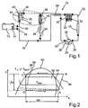
- Fig. 1 schematically shows a cooling arrangement 10 for cooling an electric unit 12, which is presently designed as a lithium-ion battery of a motor vehicle not shown in detail.
- the electric unit 12 as a fuel cell or the like under load heat-releasing aggregate or as a result of a be formed externally heat input heatable, temperature-sensitive aggregate.
- an evaporator 14 is arranged on this, which is integrated into a refrigeration circuit 16 of the cooling arrangement 10.
- a condenser 18 is furthermore arranged, by means of which a refrigerant circulating in the refrigeration circuit 16 is to be liquefied.
- a collecting device 20 for collecting the liquefied by means of the condenser 18 refrigerant is arranged downstream of the condenser 18.
- a presently designed as a submersible pump device 22 is arranged in the collecting device and designed for conveying liquefied refrigerant.
- the refrigerant in the condenser 18 may be liquefied and supplied to the evaporator 14 in the liquefied state. If a temperature of the evaporator 14 is above the ambient temperature, then the liquid refrigerant in the evaporator 14 may partially or completely evaporate, flow back to the condenser 18 and be liquefied there again at least partially. For evaporating the liquid refrigerant in the evaporator 14, the heat of the electric power unit 12 is supplied to the evaporator 14 and the electric power unit 12 is cooled accordingly.
- the condenser 18, a compressor 24 is connected upstream in the refrigeration cycle 16.
- the vaporizer 14 is charged with liquefied refrigerant by means of the pumping device 22, the at least partially vaporized refrigerant coming from the vaporizer 14 flows past the compressor 24 via a bridging device 26 for bridging the compressor 24.
- the bridging device 26 has a check valve 28, which can be flowed through by the refrigerant when the evaporator 14 is acted upon by the pump device 22.
- the check valve 28 and the bridging device 26 are presently integrated in the compressor 24 formed.
- no more separation points 30 are provided in the refrigeration circuit 16, as are to be provided anyway when arranging the compressor 24. This is important in view of that an increase in a number of the separation points 30, which in the Fig. 1 upstream and downstream, respectively the components of the refrigeration cycle 16 are indicated schematically, could lead to a higher susceptibility to leakage of the cooling arrangement 10.
- a check valve 32 arranged in the collecting device 20 is arranged parallel to the pumping device 22, so that when the evaporator 14 is acted upon by the compressor 24, the pumping device 22 can be bridged.
- the compressor 24 is used in the present case for charging the evaporator 14 when a difference between the ambient temperature and the temperature present at the evaporator 14 is not sufficient for cooling the electric unit 12. In particular, at ambient temperatures of less than 20 ° C, however, a cooling of the electric unit 12 by means of the acted upon by the pumping device 22 with liquid refrigerant evaporator 14 is possible.
- the compressed, liquefied in the condenser 18 refrigerant is expanded by means of an evaporator 14 upstream expansion element 34.
- the expansion element 34 may be formed as a fixed throttle.
- a first shut-36 is to open in the refrigeration cycle 16, and thereby a bypass device 38 for bypassing the expansion element 34 release.
- the bypass device 38 can be shut off by means of the first shut-off device 36.
- a second shut-off device 40 which is connected upstream of the expansion element 34, can be opened.
- shut-off devices 36, 40 and the expansion element 34 may be integrally formed in a loading module 42, whereby a number of separation points 30 can be kept low.
- Fig. 1 the refrigeration cycle 16 to another evaporator 44, which is provided for cooling a passenger compartment of the motor vehicle.
- the further evaporator 44 is connected in parallel in the refrigeration cycle 16 to the evaporator 14 for cooling the electric unit 12.
- the refrigerant circulates in the refrigeration circuit 16 due to the operation of the compressor 24.
- the further evaporator 44 for cooling the passenger compartment of the motor vehicle is according to Fig. 1 preceded by a further expansion element 46, by means of which the compressed by means of the compressor 24, liquefied in the condenser 18 refrigerant is depressurized.
- the further expansion element 46 may be formed as a thermostatic expansion valve.
- the further expansion element 46 a further shut-off device 48 upstream, by means of which a flow through the further expansion element 46 is to be prevented.
- the further expansion element 46 and the upstream shut-off device 48 may also be formed integrally in the admission module 42. As a result, a number of separation points 30 in the refrigeration cycle 16 is further reduced.
- thermostatic expansion valve expansion element 46 is according to Fig. 1 associated with a temperature sensor 50, by means of which a temperature downstream of the further evaporator 44 can be detected.
- a pressure sensor 52 is arranged between the capacitor 18 and the collecting device 20.
- FIG. 1 shows Fig. 1 in that the compressor 24 is preceded by an internal heat exchanger 54, by means of which heat between the compressed refrigerant and the evaporators 14, 44 exiting refrigerant is exchangeable.
- an efficiency of the cooling arrangement 10 is increased.
- the further expansion element 46 upstream shut-off valve 48 can be omitted, especially if the example designed as a thermostatic expansion valve further expansion element 46 is in the presence of a small pressure difference upstream and downstream of the pumping device 22 in a closed position. Such a small, the expansion element 46 in a closed position transferring, pressure difference is present in the refrigeration circuit 16 given when the evaporator 14 is acted upon by means of the pumping device 22 with refrigerant.
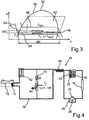
- Fig. 2 shows a pressure-enthalpy diagram, wherein on an ordinate logarithmically a pressure p of the refrigerant in the refrigeration circuit 16, and an ordinate an enthalpy h of the refrigerant are plotted.
- a trace 56 illustrates a state change in the refrigeration cycle according to FIG Fig. 1 Refrigerant when cooling the electric unit 12, wherein for acting on the evaporator 14 of the compressor 24 is operated.
- a phase boundary line 58 is drawn in which has a rising gradient up to a vertex 60 and a downward slope after vertex 60.
- the vertex 60 simultaneously represents a critical point, so that when the pressure assigned to the critical point p is exceeded, supercritical conditions are present.
- the refrigerant At pressures p below the critical point is according to Fig. 2 at comparatively low enthalpy values, the refrigerant is in the liquid state. In a region 62 delimited upward by the phase boundary line 58, there is a mixture of liquid and gaseous refrigerant. At relatively high enthalpy values of the refrigerant, the refrigerant is completely present as a gaseous phase.
- a vertex A of the contemplatnzugs 56 describes a state of the refrigerant in which it is present at comparatively low pressure P and with comparatively large enthalpy h at the entrance of the compressor 24.
- a corner B illustrates the state of the compressed by means of the compressor 24, gaseous refrigerant.
- the high-pressure refrigerant is isobaric liquefied.
- the liquefied state of the refrigerant is through the corner point C of the felicitnzugs 56 in Fig. 2 illustrated.
- the pressure p decreases of the refrigerant by a pressure difference .DELTA.p, which is to be applied when compressing the refrigerant from the compressor 24.
- FIG. 2 An in Fig. 2 indicated temperature line 64 illustrates a temperature T u of the ambient air. This is higher than a present at the electric power unit 12 temperature T Batt , which by a second temperature line 66 in Fig. 2 is shown.
- the refrigerant absorbs heat by evaporation of the liquid phase, its enthalpy changes isobaric in the Fig. 2 shown enthalpy difference .DELTA.h, which corresponds to a distance between the vertices D and A of the technicallynzugs 56.
- Fig. 2 It can be seen that for dissipating heat of the electric unit 12, that is to say for pressurizing the refrigerant with the enthalpy difference ⁇ h through the compressor 24, a comparatively high pressure change work corresponding to the pressure difference ⁇ p is used.
- Fig. 3 shows a trace 68 in the pressure-enthalpy diagram according to FIG Fig. 2 which illustrates a change in state of the refrigerant when the evaporator 14 is acted upon by means of the pump device 22.
- a temperature line 64 illustrative of the temperature T u of the ambient air is arranged below the temperature line 66, the temperature T u of the ambient air is thus lower than the temperature of the electric unit 12 cooled by the evaporator 14.
- the vertex C of the line 68 illustrates the state of FIG that of the liquid refrigerant present downstream of the condenser 18.
- the line 68 is how Fig. 3 can be seen completely within a limited by the temperature lines 64, 66 area.
- the amount of heat which can be withdrawn via the refrigerant to the electric unit 12 that is to say the enthalpy difference ⁇ h transferable to the refrigerant, is greater than the enthalpy difference ⁇ h, which in Fig. 2 is shown.
- Fig. 4 shows a further embodiment of a cooling arrangement 10, which differs from the in Fig. 1 in that the further evaporator 44 is preceded by an alternative further expansion element 70 which can be converted by driving into an open position.
- the alternative further expansion element 70 may be formed as an electrically controlled expansion valve, such as a solenoid valve. In a closed position of the further expansion element 70, the further expansion element 70 serves as a shut-off valve. In an adjustable by driving the further expansion element 70 open position of the further expansion element 70, the further expansion element 70 can be largely flowed through throttle free.
- This function of transferring the further expansion element 70 into the open position can be used if the air present in front of the further evaporator 44 has a higher temperature T L than the temperature T u of the ambient air.
- the air flowing into the further evaporator 44 in a climate box of the motor vehicle can be heated to temperatures of 5 ° K to 10 ° K by heat input from an internal combustion engine and / or exhaust system operated in particular under high load and / or by waste heat from electric motors, electronic components and the like be warmed to the temperature T u of the ambient air.
- This heat input can be increased again by a recirculation mode and / or strong sunlight.
- the heated air can be cooled in the air box to values just above the temperature T u of the ambient air by the pumping device 22, the throttle throttling applied to the other evaporator 44 with liquefied refrigerant.
- the Compressor 24 is not in operation.
- the passenger compartment of the motor vehicle can thus be cooled very efficiently and fuel-efficiently by operating the pumping device 22 when the temperature T U of the ambient air is lower than the temperature T L of the air before the further evaporator 44.
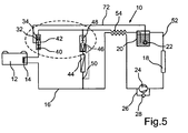
- Fig. 5 shows a further embodiment of a cooling arrangement 10, which substantially the in Fig. 1 shown embodiment of the cooling arrangement 10 corresponds. However, in the cooling arrangement 10 according to FIG Fig. 5 a bridging means 72 for bridging the inner heat exchanger 54 is provided.
- the bridging device 72 also bridges the expansion element 34 designed approximately as a fixed throttle, which is connected upstream of the evaporator 14.
- the according to Fig. 1 Check valve 32 arranged parallel to pumping device 22 in collecting device 20 is provided according to FIG Fig. 5 downstream of the expansion element 34 and upstream of a junction of the lock-up device 72 is arranged in the loading module 42.
- the shut-off device 40 assigned to the expansion element 34 is arranged downstream of the junction of the bridging device 72 in the loading module 42.
- the low enthalpy h in the liquefied refrigerant is particularly widely used to extract heat from the electric unit 12 during evaporation in the evaporator 14.
- the further evaporator 44 upstream components which according to Fig. 5 the formed as a thermostatic expansion valve further expansion element 46 with the upstream shut-off device 48 include, may be formed integrally in the admission module 42.
Landscapes
- Engineering & Computer Science (AREA)
- Manufacturing & Machinery (AREA)
- Chemical & Material Sciences (AREA)
- Chemical Kinetics & Catalysis (AREA)
- Electrochemistry (AREA)
- General Chemical & Material Sciences (AREA)
- Physics & Mathematics (AREA)
- Mechanical Engineering (AREA)
- Thermal Sciences (AREA)
- General Engineering & Computer Science (AREA)
- Sustainable Development (AREA)
- Sustainable Energy (AREA)
- Life Sciences & Earth Sciences (AREA)
- Air-Conditioning For Vehicles (AREA)
Claims (14)
- Ensemble de refroidissement destiné à refroidir un groupe sensible à la température, en particulier un groupe électrique (12), d'un véhicule automobile, comprenant un condensateur (18) destiné à liquéfier au moins un volume partiel d'un fluide frigorigène dans un circuit de refroidissement (16) et un évaporateur (14) disposé en aval du condensateur (18) qui peut recevoir le fluide frigorigène et auquel peut être amenée de la chaleur du groupe sensible à la température, en particulier du groupe électrique (12) et un dispositif de pompage (22), le circuit de refroidissement (16) présentant en aval de l'évaporateur (14) et en amont du condensateur (18) un compresseur (24) pour comprimer le fluide frigorigène et un élément d'expansion (34) disposé en amont de l'évaporateur (14) étant destiné à détendre le fluide frigorigène comprimé, au moyen du groupe de pompage l'évaporateur (14) peut recevoir au moins le volume partiel liquéfié du fluide frigorigène, caractérisé en ce qu'il est prévu un dispositif de pontage (26) destiné à ponter le compresseur (24) lorsque l'évaporateur (14) est alimenté au moyen du dispositif de pompage (22).
- Ensemble de refroidissement selon la revendication 1, caractérisé en ce que le dispositif de pompage (22), réalisé notamment comme une pompe submersible, est placé sur un dispositif collecteur (20), disposé en particulier en aval du condensateur (18), destiné à collecter le volume partiel liquéfié du fluide frigorigène.
- Ensemble de refroidissement selon la revendication 1 ou 2, caractérisé en ce que le dispositif de pontage (26) présente un clapet anti-retour (28) qui peut être traversé par le fluide frigorigène au moyen du dispositif de pompage (22) lorsque l'évaporateur (14) est alimenté.
- Ensemble de refroidissement selon la revendication 3, caractérisé en ce qu'au moyen du compresseur (24) le fluide frigorigène est soumis à une pression qui est supérieure à une pression dynamique pouvant être appliquée au maximum par le dispositif de pompage (22) lorsque le fluide frigorigène s'écoule au travers du dispositif de pompage (22).
- Ensemble de refroidissement selon l'une quelconque des revendications 3 ou 4, caractérisé en ce qu'il est prévu un dispositif de pontage, présentant notamment un clapet antiretour (32), destiné au pontage du dispositif de pompage (22) lorsque l'évaporateur (14) est alimenté au moyen du compresseur (24).
- Ensemble de refroidissement selon l'une quelconque des revendications 3 à 5, caractérisé en ce qu'il est prévu un dispositif de dérivation (38) servant à contourner l'élément d'expansion (34), ledit dispositif peut être traversé par le fluide frigorigène et fermé au moyen d'un dispositif de bouchage (36).
- Ensemble de refroidissement selon l'une quelconque des revendications 3 à 6, caractérisé en ce qu'un second dispositif de bouchage (40) affecté à l'élément d'expansion (34) empêche le passage au travers de l'élément d'expansion (34).
- Ensemble de refroidissement selon l'une quelconque des revendications 3 à 7, caractérisé en ce que le circuit de refroidissement (16) présente un autre évaporateur (44) destiné à refroidir l'habitacle du véhicule, ledit évaporateur est placé en amont d'un autre élément d'expansion (46, 70) destiné à détendre le fluide frigorigène comprimé au moyen du compresseur (24).
- Ensemble de refroidissement selon la revendication 8, caractérisé en ce qu'au moyen du dispositif de pompage (22) dans le circuit de refroidissement (22) une différence maximale peut être réglée entre une pression régnant en aval et en amont du dispositif de pompage (22), l'autre élément d'expansion (46) pouvant être amené par cette différence maximale dans une position de fermeture.
- Ensemble de refroidissement selon la revendication 8 ou 9, caractérisé en ce que l'autre élément d'expansion (46) est associé à un autre dispositif de bouchage (48) qui empêche le passage au travers de l'autre élément d'expansion (46).
- Ensemble de refroidissement selon la revendication 6 à 10, caractérisé en ce que l'autre élément d'expansion (70) peut être amené dans une position d'ouverture dans laquelle l'autre élément d'expansion (70) peut être traversé du moins pratiquement sans empêchement par le fluide frigorigène.
- Ensemble de refroidissement selon les revendications 6, 7 et 11, caractérisé en ce que l'élément d'expansion (34) et les dispositifs de bouchage (36, 40) ou les éléments d'expansion (34, 46, 40) et les dispositifs de bouchage (36, 40, 48) sont intégrés dans un module d'alimentation (42).
- Ensemble de refroidissement selon l'une quelconque des revendications 3 à 12, caractérisé en ce qu'un échangeur thermique (54) interne est monté en amont du compresseur (24) au moyen duquel de la chaleur peut être échangée entre le fluide frigorigène comprimé et le fluide frigorigène sortant de l'évaporateur (14, 44).
- Ensemble de refroidissement selon la revendication 13, caractérisé en ce que le circuit de refroidissement (16) présente un dispositif de pontage (72), destiné à ponter l'échangeur thermique (54) interne, qui ponte notamment l'élément d'expansion (34) et pouvant être traversé lorsque l'évaporateur (14, 44) est alimenté par le dispositif de pompage (72).
Applications Claiming Priority (3)
| Application Number | Priority Date | Filing Date | Title |
|---|---|---|---|
| DE102008019816 | 2008-04-19 | ||
| DE102008035216A DE102008035216A1 (de) | 2008-04-19 | 2008-07-29 | Kühlanordnung und Verfahren zum Kühlen eines temperaturempfindlichen Aggregats eines Kraftfahrzeugs |
| PCT/EP2009/001286 WO2009127292A1 (fr) | 2008-04-19 | 2009-02-24 | Ensemble de refroidissement et procédé de refroidissement d'un groupe sensible à la température sur un véhicule automobile |
Publications (2)
| Publication Number | Publication Date |
|---|---|
| EP2265453A1 EP2265453A1 (fr) | 2010-12-29 |
| EP2265453B1 true EP2265453B1 (fr) | 2011-08-24 |
Family
ID=41078772
Family Applications (1)
| Application Number | Title | Priority Date | Filing Date |
|---|---|---|---|
| EP09733539A Revoked EP2265453B1 (fr) | 2008-04-19 | 2009-02-24 | Ensemble de refroidissement et procédé de refroidissement d'un groupe sensible à la température sur un véhicule automobile |
Country Status (6)
| Country | Link |
|---|---|
| US (1) | US20110108242A1 (fr) |
| EP (1) | EP2265453B1 (fr) |
| JP (1) | JP5395890B2 (fr) |
| AT (1) | ATE521491T1 (fr) |
| DE (1) | DE102008035216A1 (fr) |
| WO (1) | WO2009127292A1 (fr) |
Cited By (1)
| Publication number | Priority date | Publication date | Assignee | Title |
|---|---|---|---|---|
| DE102022117709A1 (de) | 2022-07-15 | 2024-01-18 | Bayerische Motoren Werke Aktiengesellschaft | Verfahren zum Betreiben einer Temperiereinrichtung eines Kraftfahrzeugs sowie Temperiereinrichtung für ein Kraftfahrzeug |
Families Citing this family (23)
| Publication number | Priority date | Publication date | Assignee | Title |
|---|---|---|---|---|
| DE102009023394A1 (de) | 2009-05-29 | 2010-12-30 | Airbus Deutschland Gmbh | Verbesserte Kälteerzeugungsvorrichtung, insbesondere für Flugzeuge |
| JP5320419B2 (ja) * | 2011-02-04 | 2013-10-23 | 株式会社日本自動車部品総合研究所 | 冷却装置 |
| JP5755490B2 (ja) * | 2011-04-18 | 2015-07-29 | トヨタ自動車株式会社 | 冷却装置 |
| FR2974327B1 (fr) * | 2011-04-20 | 2014-02-28 | Valeo Systemes Thermiques | Dispositif de conditionnement thermique d'un vehicule automobile |
| JP2012245857A (ja) * | 2011-05-26 | 2012-12-13 | Nippon Soken Inc | 冷却装置、冷却装置の制御方法および制御装置 |
| FR2976224B1 (fr) * | 2011-06-08 | 2013-05-31 | Valeo Systemes Thermiques | Systeme de conditionnement thermique d'un habitacle et d'une batterie electrique |
| JP5798402B2 (ja) * | 2011-08-01 | 2015-10-21 | トヨタ自動車株式会社 | 冷却装置 |
| JP5940778B2 (ja) * | 2011-08-08 | 2016-06-29 | トヨタ自動車株式会社 | 冷却装置 |
| DE102011053256A1 (de) * | 2011-09-05 | 2013-03-07 | Dr. Ing. H.C. F. Porsche Aktiengesellschaft | Kältekreislauf zum Einsatz in einem Kraftfahrzeug |
| JP2013061099A (ja) | 2011-09-12 | 2013-04-04 | Toyota Motor Corp | 熱交換装置および熱交換装置の制御方法 |
| JP5989328B2 (ja) * | 2011-11-17 | 2016-09-07 | トヨタ自動車株式会社 | 熱交換装置 |
| US9233594B2 (en) | 2012-02-23 | 2016-01-12 | Toyota Jidosha Kabushiki Kaisha | Cooling device and vehicle equipped with the same, and control method for cooling device |
| WO2013125006A1 (fr) * | 2012-02-23 | 2013-08-29 | トヨタ自動車株式会社 | Dispositif de refroidissement et véhicule monté avec ce dernier et procédé permettant de commander un dispositif de refroidissement |
| FR2987886A3 (fr) * | 2012-03-06 | 2013-09-13 | Renault Sa | Pompe a chaleur pour vehicule automobile |
| US8950201B2 (en) * | 2012-03-30 | 2015-02-10 | Trane International Inc. | System and method for cooling power electronics using heat sinks |
| KR102552112B1 (ko) * | 2016-07-11 | 2023-07-10 | 한온시스템 주식회사 | 차량용 히트 펌프 시스템 |
| FR3065325A1 (fr) * | 2017-04-14 | 2018-10-19 | Valeo Systemes Thermiques | Dispositif de gestion thermique d'un pack-batterie |
| DE102017116981A1 (de) | 2017-07-27 | 2019-01-31 | Lion Smart Gmbh | Temperiervorrichtung für eine Temperierung eines Batteriesystems, Batteriesystem sowie Verfahren zum Temperieren und/oder Löschen eines Batteriesystems |
| CN108638787B (zh) * | 2018-05-09 | 2022-01-04 | 贾宏涛 | 一种用于电动汽车的水循环式热能综合利用热管理系统 |
| CN110783939A (zh) * | 2018-07-26 | 2020-02-11 | 深圳市瑞能实业股份有限公司 | 一种智能能量管理系统及总管理系统 |
| ES2889698B2 (es) * | 2020-06-24 | 2023-04-28 | Seat Sa | Sistema de refrigeración de al menos un elemento a refrigerar para un vehículo |
| CN113488717A (zh) * | 2021-06-08 | 2021-10-08 | 同济大学 | 一种车用软包锂离子动力电池的雾化冷却方法及装置 |
| CN114094139B (zh) * | 2022-01-18 | 2022-04-22 | 武汉海亿新能源科技有限公司 | 一种多层次热管理控制的燃料电池系统 |
Family Cites Families (16)
| Publication number | Priority date | Publication date | Assignee | Title |
|---|---|---|---|---|
| US4434624A (en) * | 1981-03-27 | 1984-03-06 | Lockheed Corporation | Energy-efficient all-electric ECS for aircraft |
| US4599873A (en) * | 1984-01-31 | 1986-07-15 | Hyde Robert E | Apparatus for maximizing refrigeration capacity |
| JPH04251163A (ja) * | 1990-12-06 | 1992-09-07 | Nippondenso Co Ltd | 自動車用空調装置 |
| US5626025A (en) * | 1991-03-08 | 1997-05-06 | Hyde; Robert E. | Liquid pressure amplification with bypass |
| CA2298373A1 (fr) * | 2000-02-11 | 2001-08-11 | Joseph Antoine Michel Grenier | Systeme de refroidissement avec refroidissement naturel accru |
| JP4540812B2 (ja) * | 2000-08-11 | 2010-09-08 | 株式会社Nttファシリティーズ | 空調機 |
| JP4352604B2 (ja) * | 2000-09-29 | 2009-10-28 | 三菱電機株式会社 | 空気調和装置 |
| DE10128164A1 (de) * | 2001-06-09 | 2002-12-12 | Behr Gmbh & Co | Fahrzeug-Kühlsystem für eine temperaturerhöhende Einrichtung sowie Verfahren zur Kühlung der temperaturerhöhenden Einrichtung |
| NO320664B1 (no) * | 2001-12-19 | 2006-01-16 | Sinvent As | System for oppvarming og kjoling av kjoretoy |
| DE10201741A1 (de) * | 2002-01-18 | 2003-08-07 | Daimler Chrysler Ag | Fahrzeug mit einer Klimatisierung und einer Wärmequelle |
| US7096683B2 (en) * | 2003-09-12 | 2006-08-29 | Ford Global Technologies, Llc | Vehicle cooling system |
| JP2005090862A (ja) * | 2003-09-17 | 2005-04-07 | Toyota Motor Corp | 冷却システム |
| DE10343225B3 (de) * | 2003-09-18 | 2005-04-14 | Webasto Ag | System zum Heizen und Kühlen eines Innenraums eines Fahrzeugs |
| JP2006216303A (ja) * | 2005-02-02 | 2006-08-17 | Denso Corp | 発熱機器の冷却構造 |
| JP2008055990A (ja) * | 2006-08-30 | 2008-03-13 | Calsonic Kansei Corp | 車両用バッテリ冷却システム |
| FR2905309B1 (fr) * | 2006-08-30 | 2015-03-27 | Peugeot Citroen Automobiles Sa | Systeme de climatisation pour vehicule automobile avec circuit secondaire pour alimenter la batterie |
-
2008
- 2008-07-29 DE DE102008035216A patent/DE102008035216A1/de not_active Withdrawn
-
2009
- 2009-02-24 WO PCT/EP2009/001286 patent/WO2009127292A1/fr active Application Filing
- 2009-02-24 EP EP09733539A patent/EP2265453B1/fr not_active Revoked
- 2009-02-24 JP JP2011504333A patent/JP5395890B2/ja not_active Expired - Fee Related
- 2009-02-24 US US12/988,605 patent/US20110108242A1/en not_active Abandoned
- 2009-02-24 AT AT09733539T patent/ATE521491T1/de active
Cited By (1)
| Publication number | Priority date | Publication date | Assignee | Title |
|---|---|---|---|---|
| DE102022117709A1 (de) | 2022-07-15 | 2024-01-18 | Bayerische Motoren Werke Aktiengesellschaft | Verfahren zum Betreiben einer Temperiereinrichtung eines Kraftfahrzeugs sowie Temperiereinrichtung für ein Kraftfahrzeug |
Also Published As
| Publication number | Publication date |
|---|---|
| DE102008035216A1 (de) | 2009-10-22 |
| WO2009127292A1 (fr) | 2009-10-22 |
| ATE521491T1 (de) | 2011-09-15 |
| JP5395890B2 (ja) | 2014-01-22 |
| US20110108242A1 (en) | 2011-05-12 |
| EP2265453A1 (fr) | 2010-12-29 |
| JP2011518301A (ja) | 2011-06-23 |
Similar Documents
| Publication | Publication Date | Title |
|---|---|---|
| EP2265453B1 (fr) | Ensemble de refroidissement et procédé de refroidissement d'un groupe sensible à la température sur un véhicule automobile | |
| EP2519415B1 (fr) | Système de climatisation pour un véhicule et procédé de thermorégulation | |
| DE102019109796A1 (de) | Wärmestrommanagementvorrichtung und Verfahren zum Betreiben einer Wärmestrommanagementvorrichtung | |
| DE102011118162B4 (de) | Kombinierte Kälteanlage und Wärmepumpe und Verfahren zum Betreiben der Anlage mit funktionsabhängiger Kältemittelverlagerung innerhalb des Kältemittelkreislaufes | |
| DE102016121362A1 (de) | Vorrichtung zur Wärmeverteilung in einem Kraftfahrzeug und Verfahren zum Betreiben der Vorrichtung | |
| EP3697635B1 (fr) | Procédé servant à faire fonctionner un circuit frigorifique ainsi qu'une installation de réfrigération de véhicule | |
| DE102015122721B4 (de) | Klimatisierungssystem eines Kraftfahrzeugs und Verfahren zum Betreiben des Klimatisierungssystems | |
| DE102012022564B4 (de) | Kraftfahrzeug mit einer Klimatisierungsvorrichtung und Betriebsverfahren dafür | |
| DE102020107111A1 (de) | Wärmepumpenanordnung für Fahrzeuge mit einem Fahrzeugkabinenheizkreislauf und einem Batterieheizkreislauf | |
| DE102020117471B4 (de) | Wärmepumpenanordnung mit indirekter Batterieerwärmung für batteriebetriebene Kraftfahrzeuge und Verfahren zum Betreiben einer Wärmepumpenanordnung | |
| DE102009035329A1 (de) | Verfahren und Vorrichtung zum Betrieb eines Fahrzeuges | |
| DE102017100591B3 (de) | Kältemittelkreislauf, insbesondere für Kraftfahrzeuge mit Elektro- oder Hybridantrieb und Verfahren zum Betreiben des Kältemittelkreislaufes | |
| DE102017204116B4 (de) | Kälteanlage eines Fahrzeugs mit einem als Kältekreislauf für einen Kältebetrieb und als Wärmepumpenkreislauf für einen Heizbetrieb betreibbaren Kältemittelkreislauf | |
| EP2287952B1 (fr) | Dispositif de régulation | |
| DE102018114762B4 (de) | Verfahren zum Betreiben einer Klimaanlage eines Kraftfahrzeuges | |
| DE102018207049A1 (de) | Kälteanlage für ein Fahrzeug mit einem eine Wärmepumpenfunktion aufweisenden Kältemittelkreislauf | |
| DE102018113687A1 (de) | Vorrichtung und Verfahren zur Kühlung von Batteriezellenmodulen | |
| DE102018214211A1 (de) | Einrichtung und Verfahren zum Temperieren eines elektrischen Energiespeichers für ein Kraftfahrzeug | |
| DE102012212227A1 (de) | Kälteanlage und Kraftfahrzeug mit einer Kälteanlage | |
| DE102017124811A1 (de) | Klimatisierungssystem zum Konditionieren der Luft eines Fahrgastraums eines Kraftfahrzeugs und Verfahren zum Betreiben des Klimatisierungssystems | |
| DE102020111511A1 (de) | Kälteanlagen- und Wärmepumpenanordnung für batterie-betriebene Fahrzeuge und Verfahren zum Betreiben einer Kälteanlagen- und Wärmepumpenanordnung | |
| DE102017213973A1 (de) | Verfahren zum Betreiben einer Kälteanlage eines Fahrzeugs mit einem eine Kühl- und Heizfunktion aufweisenden Kältemittelkreislauf | |
| DE102017201686A1 (de) | Verfahren zum Betreiben einer Kälteanlage eines Fahrzeugs | |
| EP4366964A1 (fr) | Circuit de réfrigération ainsi que système de gestion thermique et véhicule motorisé comportant un circuit de réfrigération de ce type | |
| DE102013211398A1 (de) | Abwärmerückgewinnungssystem für eine Brennkraftmaschine |
Legal Events
| Date | Code | Title | Description |
|---|---|---|---|
| PUAI | Public reference made under article 153(3) epc to a published international application that has entered the european phase |
Free format text: ORIGINAL CODE: 0009012 |
|
| 17P | Request for examination filed |
Effective date: 20100922 |
|
| AK | Designated contracting states |
Kind code of ref document: A1 Designated state(s): AT BE BG CH CY CZ DE DK EE ES FI FR GB GR HR HU IE IS IT LI LT LU LV MC MK MT NL NO PL PT RO SE SI SK TR |
|
| AX | Request for extension of the european patent |
Extension state: AL BA RS |
|
| GRAP | Despatch of communication of intention to grant a patent |
Free format text: ORIGINAL CODE: EPIDOSNIGR1 |
|
| DAX | Request for extension of the european patent (deleted) | ||
| GRAS | Grant fee paid |
Free format text: ORIGINAL CODE: EPIDOSNIGR3 |
|
| GRAA | (expected) grant |
Free format text: ORIGINAL CODE: 0009210 |
|
| AK | Designated contracting states |
Kind code of ref document: B1 Designated state(s): AT BE BG CH CY CZ DE DK EE ES FI FR GB GR HR HU IE IS IT LI LT LU LV MC MK MT NL NO PL PT RO SE SI SK TR |
|
| REG | Reference to a national code |
Ref country code: GB Ref legal event code: FG4D Free format text: NOT ENGLISH |
|
| REG | Reference to a national code |
Ref country code: CH Ref legal event code: EP |
|
| REG | Reference to a national code |
Ref country code: IE Ref legal event code: FG4D Free format text: LANGUAGE OF EP DOCUMENT: GERMAN |
|
| REG | Reference to a national code |
Ref country code: DE Ref legal event code: R096 Ref document number: 502009001200 Country of ref document: DE Effective date: 20111020 |
|
| REG | Reference to a national code |
Ref country code: NL Ref legal event code: VDEP Effective date: 20110824 |
|
| LTIE | Lt: invalidation of european patent or patent extension |
Effective date: 20110824 |
|
| PG25 | Lapsed in a contracting state [announced via postgrant information from national office to epo] |
Ref country code: NL Free format text: LAPSE BECAUSE OF FAILURE TO SUBMIT A TRANSLATION OF THE DESCRIPTION OR TO PAY THE FEE WITHIN THE PRESCRIBED TIME-LIMIT Effective date: 20110824 Ref country code: SE Free format text: LAPSE BECAUSE OF FAILURE TO SUBMIT A TRANSLATION OF THE DESCRIPTION OR TO PAY THE FEE WITHIN THE PRESCRIBED TIME-LIMIT Effective date: 20110824 Ref country code: FI Free format text: LAPSE BECAUSE OF FAILURE TO SUBMIT A TRANSLATION OF THE DESCRIPTION OR TO PAY THE FEE WITHIN THE PRESCRIBED TIME-LIMIT Effective date: 20110824 Ref country code: HR Free format text: LAPSE BECAUSE OF FAILURE TO SUBMIT A TRANSLATION OF THE DESCRIPTION OR TO PAY THE FEE WITHIN THE PRESCRIBED TIME-LIMIT Effective date: 20110824 Ref country code: IS Free format text: LAPSE BECAUSE OF FAILURE TO SUBMIT A TRANSLATION OF THE DESCRIPTION OR TO PAY THE FEE WITHIN THE PRESCRIBED TIME-LIMIT Effective date: 20111224 Ref country code: LT Free format text: LAPSE BECAUSE OF FAILURE TO SUBMIT A TRANSLATION OF THE DESCRIPTION OR TO PAY THE FEE WITHIN THE PRESCRIBED TIME-LIMIT Effective date: 20110824 Ref country code: PT Free format text: LAPSE BECAUSE OF FAILURE TO SUBMIT A TRANSLATION OF THE DESCRIPTION OR TO PAY THE FEE WITHIN THE PRESCRIBED TIME-LIMIT Effective date: 20111226 Ref country code: NO Free format text: LAPSE BECAUSE OF FAILURE TO SUBMIT A TRANSLATION OF THE DESCRIPTION OR TO PAY THE FEE WITHIN THE PRESCRIBED TIME-LIMIT Effective date: 20111124 |
|
| PG25 | Lapsed in a contracting state [announced via postgrant information from national office to epo] |
Ref country code: GR Free format text: LAPSE BECAUSE OF FAILURE TO SUBMIT A TRANSLATION OF THE DESCRIPTION OR TO PAY THE FEE WITHIN THE PRESCRIBED TIME-LIMIT Effective date: 20111125 Ref country code: PL Free format text: LAPSE BECAUSE OF FAILURE TO SUBMIT A TRANSLATION OF THE DESCRIPTION OR TO PAY THE FEE WITHIN THE PRESCRIBED TIME-LIMIT Effective date: 20110824 Ref country code: SI Free format text: LAPSE BECAUSE OF FAILURE TO SUBMIT A TRANSLATION OF THE DESCRIPTION OR TO PAY THE FEE WITHIN THE PRESCRIBED TIME-LIMIT Effective date: 20110824 Ref country code: LV Free format text: LAPSE BECAUSE OF FAILURE TO SUBMIT A TRANSLATION OF THE DESCRIPTION OR TO PAY THE FEE WITHIN THE PRESCRIBED TIME-LIMIT Effective date: 20110824 Ref country code: CY Free format text: LAPSE BECAUSE OF FAILURE TO SUBMIT A TRANSLATION OF THE DESCRIPTION OR TO PAY THE FEE WITHIN THE PRESCRIBED TIME-LIMIT Effective date: 20110824 |
|
| REG | Reference to a national code |
Ref country code: IE Ref legal event code: FD4D |
|
| PG25 | Lapsed in a contracting state [announced via postgrant information from national office to epo] |
Ref country code: SK Free format text: LAPSE BECAUSE OF FAILURE TO SUBMIT A TRANSLATION OF THE DESCRIPTION OR TO PAY THE FEE WITHIN THE PRESCRIBED TIME-LIMIT Effective date: 20110824 Ref country code: IE Free format text: LAPSE BECAUSE OF FAILURE TO SUBMIT A TRANSLATION OF THE DESCRIPTION OR TO PAY THE FEE WITHIN THE PRESCRIBED TIME-LIMIT Effective date: 20110824 Ref country code: CZ Free format text: LAPSE BECAUSE OF FAILURE TO SUBMIT A TRANSLATION OF THE DESCRIPTION OR TO PAY THE FEE WITHIN THE PRESCRIBED TIME-LIMIT Effective date: 20110824 |
|
| PG25 | Lapsed in a contracting state [announced via postgrant information from national office to epo] |
Ref country code: EE Free format text: LAPSE BECAUSE OF FAILURE TO SUBMIT A TRANSLATION OF THE DESCRIPTION OR TO PAY THE FEE WITHIN THE PRESCRIBED TIME-LIMIT Effective date: 20110824 Ref country code: IT Free format text: LAPSE BECAUSE OF FAILURE TO SUBMIT A TRANSLATION OF THE DESCRIPTION OR TO PAY THE FEE WITHIN THE PRESCRIBED TIME-LIMIT Effective date: 20110824 Ref country code: RO Free format text: LAPSE BECAUSE OF FAILURE TO SUBMIT A TRANSLATION OF THE DESCRIPTION OR TO PAY THE FEE WITHIN THE PRESCRIBED TIME-LIMIT Effective date: 20110824 |
|
| PLBI | Opposition filed |
Free format text: ORIGINAL CODE: 0009260 |
|
| PLAX | Notice of opposition and request to file observation + time limit sent |
Free format text: ORIGINAL CODE: EPIDOSNOBS2 |
|
| PG25 | Lapsed in a contracting state [announced via postgrant information from national office to epo] |
Ref country code: DK Free format text: LAPSE BECAUSE OF FAILURE TO SUBMIT A TRANSLATION OF THE DESCRIPTION OR TO PAY THE FEE WITHIN THE PRESCRIBED TIME-LIMIT Effective date: 20110824 |
|
| 26 | Opposition filed |
Opponent name: RITTAL GMBH & CO. KG Effective date: 20120524 |
|
| REG | Reference to a national code |
Ref country code: DE Ref legal event code: R026 Ref document number: 502009001200 Country of ref document: DE Effective date: 20120524 |
|
| BERE | Be: lapsed |
Owner name: DAIMLER A.G. Effective date: 20120228 |
|
| PG25 | Lapsed in a contracting state [announced via postgrant information from national office to epo] |
Ref country code: MC Free format text: LAPSE BECAUSE OF NON-PAYMENT OF DUE FEES Effective date: 20120229 |
|
| PLBB | Reply of patent proprietor to notice(s) of opposition received |
Free format text: ORIGINAL CODE: EPIDOSNOBS3 |
|
| PG25 | Lapsed in a contracting state [announced via postgrant information from national office to epo] |
Ref country code: BE Free format text: LAPSE BECAUSE OF NON-PAYMENT OF DUE FEES Effective date: 20120228 |
|
| PG25 | Lapsed in a contracting state [announced via postgrant information from national office to epo] |
Ref country code: MK Free format text: LAPSE BECAUSE OF FAILURE TO SUBMIT A TRANSLATION OF THE DESCRIPTION OR TO PAY THE FEE WITHIN THE PRESCRIBED TIME-LIMIT Effective date: 20110824 |
|
| PG25 | Lapsed in a contracting state [announced via postgrant information from national office to epo] |
Ref country code: ES Free format text: LAPSE BECAUSE OF FAILURE TO SUBMIT A TRANSLATION OF THE DESCRIPTION OR TO PAY THE FEE WITHIN THE PRESCRIBED TIME-LIMIT Effective date: 20111205 |
|
| PG25 | Lapsed in a contracting state [announced via postgrant information from national office to epo] |
Ref country code: BG Free format text: LAPSE BECAUSE OF FAILURE TO SUBMIT A TRANSLATION OF THE DESCRIPTION OR TO PAY THE FEE WITHIN THE PRESCRIBED TIME-LIMIT Effective date: 20111124 |
|
| PG25 | Lapsed in a contracting state [announced via postgrant information from national office to epo] |
Ref country code: MT Free format text: LAPSE BECAUSE OF FAILURE TO SUBMIT A TRANSLATION OF THE DESCRIPTION OR TO PAY THE FEE WITHIN THE PRESCRIBED TIME-LIMIT Effective date: 20110824 |
|
| REG | Reference to a national code |
Ref country code: CH Ref legal event code: PL |
|
| PG25 | Lapsed in a contracting state [announced via postgrant information from national office to epo] |
Ref country code: CH Free format text: LAPSE BECAUSE OF NON-PAYMENT OF DUE FEES Effective date: 20130228 Ref country code: LI Free format text: LAPSE BECAUSE OF NON-PAYMENT OF DUE FEES Effective date: 20130228 |
|
| PG25 | Lapsed in a contracting state [announced via postgrant information from national office to epo] |
Ref country code: TR Free format text: LAPSE BECAUSE OF FAILURE TO SUBMIT A TRANSLATION OF THE DESCRIPTION OR TO PAY THE FEE WITHIN THE PRESCRIBED TIME-LIMIT Effective date: 20110824 |
|
| PG25 | Lapsed in a contracting state [announced via postgrant information from national office to epo] |
Ref country code: LU Free format text: LAPSE BECAUSE OF NON-PAYMENT OF DUE FEES Effective date: 20120224 |
|
| PGFP | Annual fee paid to national office [announced via postgrant information from national office to epo] |
Ref country code: FR Payment date: 20140226 Year of fee payment: 6 |
|
| PGFP | Annual fee paid to national office [announced via postgrant information from national office to epo] |
Ref country code: GB Payment date: 20140228 Year of fee payment: 6 |
|
| PG25 | Lapsed in a contracting state [announced via postgrant information from national office to epo] |
Ref country code: HU Free format text: LAPSE BECAUSE OF FAILURE TO SUBMIT A TRANSLATION OF THE DESCRIPTION OR TO PAY THE FEE WITHIN THE PRESCRIBED TIME-LIMIT Effective date: 20090224 |
|
| REG | Reference to a national code |
Ref country code: AT Ref legal event code: MM01 Ref document number: 521491 Country of ref document: AT Kind code of ref document: T Effective date: 20140224 |
|
| RDAF | Communication despatched that patent is revoked |
Free format text: ORIGINAL CODE: EPIDOSNREV1 |
|
| PG25 | Lapsed in a contracting state [announced via postgrant information from national office to epo] |
Ref country code: AT Free format text: LAPSE BECAUSE OF NON-PAYMENT OF DUE FEES Effective date: 20140224 |
|
| REG | Reference to a national code |
Ref country code: DE Ref legal event code: R064 Ref document number: 502009001200 Country of ref document: DE Ref country code: DE Ref legal event code: R103 Ref document number: 502009001200 Country of ref document: DE |
|
| PGFP | Annual fee paid to national office [announced via postgrant information from national office to epo] |
Ref country code: DE Payment date: 20150429 Year of fee payment: 7 |
|
| RDAG | Patent revoked |
Free format text: ORIGINAL CODE: 0009271 |
|
| STAA | Information on the status of an ep patent application or granted ep patent |
Free format text: STATUS: PATENT REVOKED |
|
| 27W | Patent revoked |
Effective date: 20150608 |
|
| GBPR | Gb: patent revoked under art. 102 of the ep convention designating the uk as contracting state |
Effective date: 20150608 |
|
| REG | Reference to a national code |
Ref country code: AT Ref legal event code: MA03 Ref document number: 521491 Country of ref document: AT Kind code of ref document: T Effective date: 20150608 |