EP2265453B1 - Cooling arrangement and method for cooling a temperature-sensitive assembly of a motor vehicle - Google Patents
Cooling arrangement and method for cooling a temperature-sensitive assembly of a motor vehicle Download PDFInfo
- Publication number
- EP2265453B1 EP2265453B1 EP09733539A EP09733539A EP2265453B1 EP 2265453 B1 EP2265453 B1 EP 2265453B1 EP 09733539 A EP09733539 A EP 09733539A EP 09733539 A EP09733539 A EP 09733539A EP 2265453 B1 EP2265453 B1 EP 2265453B1
- Authority
- EP
- European Patent Office
- Prior art keywords
- refrigerant
- evaporator
- cooling
- expansion element
- cooling arrangement
- Prior art date
- Legal status (The legal status is an assumption and is not a legal conclusion. Google has not performed a legal analysis and makes no representation as to the accuracy of the status listed.)
- Revoked
Links
Images
Classifications
-
- B—PERFORMING OPERATIONS; TRANSPORTING
- B60—VEHICLES IN GENERAL
- B60H—ARRANGEMENTS OF HEATING, COOLING, VENTILATING OR OTHER AIR-TREATING DEVICES SPECIALLY ADAPTED FOR PASSENGER OR GOODS SPACES OF VEHICLES
- B60H1/00—Heating, cooling or ventilating [HVAC] devices
- B60H1/00271—HVAC devices specially adapted for particular vehicle parts or components and being connected to the vehicle HVAC unit
- B60H1/00278—HVAC devices specially adapted for particular vehicle parts or components and being connected to the vehicle HVAC unit for the battery
-
- F—MECHANICAL ENGINEERING; LIGHTING; HEATING; WEAPONS; BLASTING
- F25—REFRIGERATION OR COOLING; COMBINED HEATING AND REFRIGERATION SYSTEMS; HEAT PUMP SYSTEMS; MANUFACTURE OR STORAGE OF ICE; LIQUEFACTION SOLIDIFICATION OF GASES
- F25B—REFRIGERATION MACHINES, PLANTS OR SYSTEMS; COMBINED HEATING AND REFRIGERATION SYSTEMS; HEAT PUMP SYSTEMS
- F25B41/00—Fluid-circulation arrangements
-
- F—MECHANICAL ENGINEERING; LIGHTING; HEATING; WEAPONS; BLASTING
- F25—REFRIGERATION OR COOLING; COMBINED HEATING AND REFRIGERATION SYSTEMS; HEAT PUMP SYSTEMS; MANUFACTURE OR STORAGE OF ICE; LIQUEFACTION SOLIDIFICATION OF GASES
- F25B—REFRIGERATION MACHINES, PLANTS OR SYSTEMS; COMBINED HEATING AND REFRIGERATION SYSTEMS; HEAT PUMP SYSTEMS
- F25B5/00—Compression machines, plants or systems, with several evaporator circuits, e.g. for varying refrigerating capacity
- F25B5/02—Compression machines, plants or systems, with several evaporator circuits, e.g. for varying refrigerating capacity arranged in parallel
-
- H—ELECTRICITY
- H01—ELECTRIC ELEMENTS
- H01M—PROCESSES OR MEANS, e.g. BATTERIES, FOR THE DIRECT CONVERSION OF CHEMICAL ENERGY INTO ELECTRICAL ENERGY
- H01M10/00—Secondary cells; Manufacture thereof
- H01M10/60—Heating or cooling; Temperature control
- H01M10/61—Types of temperature control
- H01M10/613—Cooling or keeping cold
-
- H—ELECTRICITY
- H01—ELECTRIC ELEMENTS
- H01M—PROCESSES OR MEANS, e.g. BATTERIES, FOR THE DIRECT CONVERSION OF CHEMICAL ENERGY INTO ELECTRICAL ENERGY
- H01M10/00—Secondary cells; Manufacture thereof
- H01M10/60—Heating or cooling; Temperature control
- H01M10/62—Heating or cooling; Temperature control specially adapted for specific applications
- H01M10/625—Vehicles
-
- H—ELECTRICITY
- H01—ELECTRIC ELEMENTS
- H01M—PROCESSES OR MEANS, e.g. BATTERIES, FOR THE DIRECT CONVERSION OF CHEMICAL ENERGY INTO ELECTRICAL ENERGY
- H01M10/00—Secondary cells; Manufacture thereof
- H01M10/60—Heating or cooling; Temperature control
- H01M10/65—Means for temperature control structurally associated with the cells
- H01M10/656—Means for temperature control structurally associated with the cells characterised by the type of heat-exchange fluid
- H01M10/6569—Fluids undergoing a liquid-gas phase change or transition, e.g. evaporation or condensation
-
- H—ELECTRICITY
- H01—ELECTRIC ELEMENTS
- H01M—PROCESSES OR MEANS, e.g. BATTERIES, FOR THE DIRECT CONVERSION OF CHEMICAL ENERGY INTO ELECTRICAL ENERGY
- H01M8/00—Fuel cells; Manufacture thereof
- H01M8/04—Auxiliary arrangements, e.g. for control of pressure or for circulation of fluids
- H01M8/04007—Auxiliary arrangements, e.g. for control of pressure or for circulation of fluids related to heat exchange
- H01M8/04029—Heat exchange using liquids
-
- B—PERFORMING OPERATIONS; TRANSPORTING
- B60—VEHICLES IN GENERAL
- B60H—ARRANGEMENTS OF HEATING, COOLING, VENTILATING OR OTHER AIR-TREATING DEVICES SPECIALLY ADAPTED FOR PASSENGER OR GOODS SPACES OF VEHICLES
- B60H1/00—Heating, cooling or ventilating [HVAC] devices
- B60H1/00642—Control systems or circuits; Control members or indication devices for heating, cooling or ventilating devices
- B60H1/00814—Control systems or circuits characterised by their output, for controlling particular components of the heating, cooling or ventilating installation
- B60H1/00878—Control systems or circuits characterised by their output, for controlling particular components of the heating, cooling or ventilating installation the components being temperature regulating devices
- B60H2001/00949—Control systems or circuits characterised by their output, for controlling particular components of the heating, cooling or ventilating installation the components being temperature regulating devices comprising additional heating/cooling sources, e.g. second evaporator
-
- F—MECHANICAL ENGINEERING; LIGHTING; HEATING; WEAPONS; BLASTING
- F25—REFRIGERATION OR COOLING; COMBINED HEATING AND REFRIGERATION SYSTEMS; HEAT PUMP SYSTEMS; MANUFACTURE OR STORAGE OF ICE; LIQUEFACTION SOLIDIFICATION OF GASES
- F25B—REFRIGERATION MACHINES, PLANTS OR SYSTEMS; COMBINED HEATING AND REFRIGERATION SYSTEMS; HEAT PUMP SYSTEMS
- F25B2400/00—General features or devices for refrigeration machines, plants or systems, combined heating and refrigeration systems or heat-pump systems, i.e. not limited to a particular subgroup of F25B
- F25B2400/01—Heaters
-
- F—MECHANICAL ENGINEERING; LIGHTING; HEATING; WEAPONS; BLASTING
- F25—REFRIGERATION OR COOLING; COMBINED HEATING AND REFRIGERATION SYSTEMS; HEAT PUMP SYSTEMS; MANUFACTURE OR STORAGE OF ICE; LIQUEFACTION SOLIDIFICATION OF GASES
- F25B—REFRIGERATION MACHINES, PLANTS OR SYSTEMS; COMBINED HEATING AND REFRIGERATION SYSTEMS; HEAT PUMP SYSTEMS
- F25B2400/00—General features or devices for refrigeration machines, plants or systems, combined heating and refrigeration systems or heat-pump systems, i.e. not limited to a particular subgroup of F25B
- F25B2400/04—Refrigeration circuit bypassing means
- F25B2400/0401—Refrigeration circuit bypassing means for the compressor
-
- F—MECHANICAL ENGINEERING; LIGHTING; HEATING; WEAPONS; BLASTING
- F25—REFRIGERATION OR COOLING; COMBINED HEATING AND REFRIGERATION SYSTEMS; HEAT PUMP SYSTEMS; MANUFACTURE OR STORAGE OF ICE; LIQUEFACTION SOLIDIFICATION OF GASES
- F25B—REFRIGERATION MACHINES, PLANTS OR SYSTEMS; COMBINED HEATING AND REFRIGERATION SYSTEMS; HEAT PUMP SYSTEMS
- F25B2400/00—General features or devices for refrigeration machines, plants or systems, combined heating and refrigeration systems or heat-pump systems, i.e. not limited to a particular subgroup of F25B
- F25B2400/16—Receivers
-
- F—MECHANICAL ENGINEERING; LIGHTING; HEATING; WEAPONS; BLASTING
- F25—REFRIGERATION OR COOLING; COMBINED HEATING AND REFRIGERATION SYSTEMS; HEAT PUMP SYSTEMS; MANUFACTURE OR STORAGE OF ICE; LIQUEFACTION SOLIDIFICATION OF GASES
- F25B—REFRIGERATION MACHINES, PLANTS OR SYSTEMS; COMBINED HEATING AND REFRIGERATION SYSTEMS; HEAT PUMP SYSTEMS
- F25B40/00—Subcoolers, desuperheaters or superheaters
-
- F—MECHANICAL ENGINEERING; LIGHTING; HEATING; WEAPONS; BLASTING
- F25—REFRIGERATION OR COOLING; COMBINED HEATING AND REFRIGERATION SYSTEMS; HEAT PUMP SYSTEMS; MANUFACTURE OR STORAGE OF ICE; LIQUEFACTION SOLIDIFICATION OF GASES
- F25D—REFRIGERATORS; COLD ROOMS; ICE-BOXES; COOLING OR FREEZING APPARATUS NOT OTHERWISE PROVIDED FOR
- F25D16/00—Devices using a combination of a cooling mode associated with refrigerating machinery with a cooling mode not associated with refrigerating machinery
-
- H—ELECTRICITY
- H01—ELECTRIC ELEMENTS
- H01M—PROCESSES OR MEANS, e.g. BATTERIES, FOR THE DIRECT CONVERSION OF CHEMICAL ENERGY INTO ELECTRICAL ENERGY
- H01M2250/00—Fuel cells for particular applications; Specific features of fuel cell system
- H01M2250/20—Fuel cells in motive systems, e.g. vehicle, ship, plane
-
- Y—GENERAL TAGGING OF NEW TECHNOLOGICAL DEVELOPMENTS; GENERAL TAGGING OF CROSS-SECTIONAL TECHNOLOGIES SPANNING OVER SEVERAL SECTIONS OF THE IPC; TECHNICAL SUBJECTS COVERED BY FORMER USPC CROSS-REFERENCE ART COLLECTIONS [XRACs] AND DIGESTS
- Y02—TECHNOLOGIES OR APPLICATIONS FOR MITIGATION OR ADAPTATION AGAINST CLIMATE CHANGE
- Y02E—REDUCTION OF GREENHOUSE GAS [GHG] EMISSIONS, RELATED TO ENERGY GENERATION, TRANSMISSION OR DISTRIBUTION
- Y02E60/00—Enabling technologies; Technologies with a potential or indirect contribution to GHG emissions mitigation
- Y02E60/10—Energy storage using batteries
-
- Y—GENERAL TAGGING OF NEW TECHNOLOGICAL DEVELOPMENTS; GENERAL TAGGING OF CROSS-SECTIONAL TECHNOLOGIES SPANNING OVER SEVERAL SECTIONS OF THE IPC; TECHNICAL SUBJECTS COVERED BY FORMER USPC CROSS-REFERENCE ART COLLECTIONS [XRACs] AND DIGESTS
- Y02—TECHNOLOGIES OR APPLICATIONS FOR MITIGATION OR ADAPTATION AGAINST CLIMATE CHANGE
- Y02E—REDUCTION OF GREENHOUSE GAS [GHG] EMISSIONS, RELATED TO ENERGY GENERATION, TRANSMISSION OR DISTRIBUTION
- Y02E60/00—Enabling technologies; Technologies with a potential or indirect contribution to GHG emissions mitigation
- Y02E60/30—Hydrogen technology
- Y02E60/50—Fuel cells
-
- Y—GENERAL TAGGING OF NEW TECHNOLOGICAL DEVELOPMENTS; GENERAL TAGGING OF CROSS-SECTIONAL TECHNOLOGIES SPANNING OVER SEVERAL SECTIONS OF THE IPC; TECHNICAL SUBJECTS COVERED BY FORMER USPC CROSS-REFERENCE ART COLLECTIONS [XRACs] AND DIGESTS
- Y02—TECHNOLOGIES OR APPLICATIONS FOR MITIGATION OR ADAPTATION AGAINST CLIMATE CHANGE
- Y02T—CLIMATE CHANGE MITIGATION TECHNOLOGIES RELATED TO TRANSPORTATION
- Y02T90/00—Enabling technologies or technologies with a potential or indirect contribution to GHG emissions mitigation
- Y02T90/40—Application of hydrogen technology to transportation, e.g. using fuel cells
Definitions
- the invention relates to a cooling arrangement for cooling a temperature-sensitive aggregate, in particular an electric unit, of a motor vehicle, with a condenser for liquefying at least a partial volume of a refrigerant in a refrigeration cycle and with a downstream of the condenser arranged evaporator, which is acted upon by the refrigerant, and which heat the temperature-sensitive aggregate, in particular of the electric unit, can be fed.
- the heating may affect a functioning of the unit, at least temporarily.
- the heating may be a consequence of the operation of the unit itself and / or a consequence of an external heat input, such as an entry of waste heat from a drive unit or sunlight.
- lithium-ion batteries in particular lithium-ion batteries, fuel cells and the like heat
- an amount of heat generated by the electric power unit depends on the load state of the electric unit.
- lithium-ion batteries should be operated in a temperature range of 20 ° C to 30 ° C to avoid a significant reduction in their service life.
- an evaporator of a refrigeration system designed for cooling a passenger compartment of the motor vehicle can be arranged on the battery.
- the refrigeration system for cooling the Passenger compartment of the motor vehicle in this case has in the usual way a compressor for compressing the gaseous refrigerant, a condenser for liquefying at least a partial volume of the compressed refrigerant and an evaporator upstream expansion device for expanding the compressed refrigerant.
- the US 2005056035 A1 discloses a cooling arrangement for cooling a temperature-sensitive electrical power unit of a motor vehicle with a condenser for liquefying a partial volume of a refrigerant in a refrigeration cycle.
- the cooling arrangement has a downstream of the condenser arranged evaporator, which is acted upon by the refrigerant and which heat of the temperature-sensitive electric unit can be supplied and is provided with a pumping device. By means of the pumping device, the evaporator can be acted upon at least with the liquefied partial volume of the refrigerant.
- the WO 03/059664 A1 discloses a multi-branched refrigerant circuit for cooling vehicle components whose branches are controlled by valves.
- the WO 2008/026386 A1 also shows a cooling system for cooling vehicle batteries by means of a refrigeration system.
- WO 2008/025915 A1 are proposed combined battery cooling and air conditioning systems whose circuits are sometimes multi-branched.
- the refrigeration systems for vehicle components disclosed in these documents are all circulated conventionally via a compressor.
- the coolant circuit may contain as coolant a brine, in particular a water-glysantin mixture.
- the coolant can be cooled by means of the refrigeration system provided for cooling the passenger compartment.
- the coolant is cooled by means of an evaporator, which is arranged in a refrigeration cycle of the refrigeration system for cooling the passenger compartment.
- the cooled coolant is fed via the separate coolant circuit to the electric power unit.
- the coolant of the separate coolant circuit can cool at low ambient temperatures with ambient air.
- Object of the present invention is therefore to provide a cooling arrangement of the aforementioned type, by means of which a particularly efficient cooling of a temperature-sensitive aggregate of a motor vehicle is possible.
- the cooling arrangement according to the invention for cooling a temperature-sensitive unit, in particular electric unit, of a motor vehicle, with a condenser for liquefying at least one Partial volume of a refrigerant in a refrigeration cycle and arranged with a downstream of the condenser evaporator, which can be supplied with the heat and the heat of the temperature-sensitive unit, in particular electric unit, has a pumping means, by means of which the evaporator at least with the liquefied partial volume of the refrigerant acted upon is.
- the pumping device is in this case designed as a liquid pumping device, which is designed to convey the liquefied partial volume of the refrigerant.
- a compressor of a refrigeration cycle is designed for compressing and conveying gaseous refrigerant, wherein a pressurization of the compressor with liquid refrigerant impairs the functioning of the compressor.
- the refrigeration cycle further comprises downstream of the evaporator and upstream of the condenser, a compressor for compressing the refrigerant, wherein the evaporator is preceded by an expansion element for expanding the compressed refrigerant and wherein a bridging means is provided for bridging the compressor when the evaporator is acted upon by the pumping device.
- the invention is based on the finding that especially at temperatures of the ambient air surrounding the motor vehicle of less than 20 ° C heat of the temperature-sensitive unit with particularly low energy consumption, namely only the energy required to operate the pumping device, can be dissipated to the environment.
- the pumping device conveys at least the partial volume of the refrigerant liquefied by means of the condenser to the evaporator, wherein heat is removed from the temperature-sensitive aggregate in the form of latent heat, which is to be applied to transfer the liquefied refrigerant into a gaseous state.
- This is a particularly efficient cooling of the temperature-sensitive aggregate, in particular electric unit, the motor vehicle allows.
- the capacitor which can be arranged on air-hydraulic particularly favorable position of the motor vehicle, for particularly efficient removal of heat of the temperature-sensitive unit, in particular electric unit, is available.
- cooling the temperature-sensitive unit, in particular electric unit arranged by means of the known from the prior art separate coolant circuit for cooling the coolant in air-hydraulic and thermally unfavorable manner before the condenser or in a thermally and aerodynamically unfavorable area, such as the bottom of the Motor vehicle, a wheel arch or the like.
- the cooling arrangement is particularly compact and inexpensive to train.
- thermoelectric unit in particular the electric unit
- a particularly efficient cooling of the temperature-sensitive unit is made possible by the fact that no heat transfer losses occur during a heat transfer between different heat transfer media, such as the refrigerant and the coolant.
- lines of the refrigeration cycle which supply the refrigerant to the temperature-sensitive unit, in particular the electric unit, have a substantially smaller cross-section, as lines of the separate, the coolant conveying coolant circuit. given less efficient cooling of the temperature-sensitive aggregate and there may be temperature differences within the cooled temperature-sensitive aggregate of about 5 ° K.
- the pump device in particular designed as a submersible pump, is arranged on a collecting device arranged in particular downstream of the condenser for collecting the liquefied partial volume of the refrigerant.
- the pumping device has a particularly good startup behavior.
- the pumping device may in this case be designed in particular integrated into the collecting device, so that no additional separating points to be provided in addition to the collecting device for arranging the collecting device in the refrigeration circuit are to be arranged.
- the refrigeration circuit downstream of the evaporator and upstream of the condenser comprises a compressor for compressing the refrigerant, wherein the evaporator is preceded by an expansion element for expanding the compressed refrigerant, and wherein a bridging device for bridging the compressor when applied the evaporator is provided by means of the pumping device.
- the bridging device for bridging the compressor when the evaporator is acted upon by means of the pump device can advantageously have a check valve, which can be flowed through by the refrigerant when the evaporator is acted upon by the pump device.
- a particularly simple, operating phase-dependent closing and / or opening of the bridging device is made possible.
- the compressor can be provided that by means of the compressor, the refrigerant can be acted upon with a pressure which is greater than a maximum upon application of the refrigerant by the pumping means can be applied by means of the pumping means ram pressure.
- the compressor can thus cause a flow through the acting as a check valve pumping device.
- a bridging device in particular having a check valve, can be provided for bridging the pump device when the evaporator is acted upon by the compressor.
- the refrigerant can flow unhindered past the pump device. If the bridging device has a nonreturn valve, in addition a formation of a short-circuit flow in the collecting device during operation of the pumping device is prevented.
- a bypass device through which the refrigerant can flow is provided for bypassing the expansion element, which can be shut off by means of a first shut-off device.
- a bypass device through which the refrigerant can flow is provided for bypassing the expansion element, which can be shut off by means of a first shut-off device.
- the expansion element is associated with a second shut-off device, by means of which a flow through the expansion element is to be prevented. This can ensure that the liquefied refrigerant flows throttle-free to the evaporator when the pumping device is operated.
- first shut-off device and the second shut-off device may, for example, be integrated into a three-way valve.
- the refrigeration cycle has a further evaporator for cooling a passenger compartment of the motor vehicle, which is preceded by a further expansion element for releasing the refrigerant compressed by the compressor.
- a further expansion element for releasing the refrigerant compressed by the compressor.
- a maximum difference between an upstream and downstream of the pumping device prevailing pressure is adjustable, wherein the further expansion element can be converted by means of this maximum difference in a closed position.
- the further expansion element may be associated with a further shut-off device, by means of which a flow through the further expansion element is to be prevented.
- the further expansion element can be converted into an open position, in which the further expansion element can be flowed through by the refrigerant at least substantially unhindered.
- the further expansion element can be designed as an electrically controllable expansion element, so that when the evaporator is charged with the liquefied partial volume of the refrigerant, the liquefied refrigerant can be fed to the evaporator for throttling the passenger compartment in a throttle-free manner.
- the air flowing in the passenger compartment is heated by an increased heat input to a temperature above the ambient temperature.
- the heating can be effected in this case by operating an internal combustion engine of the motor vehicle, a fan motor, and / or other electronic components.
- an internal combustion engine and / or an exhaust system under high load and / or strong sunlight can lead to a heating of the air flowing in the passenger compartment air.
- temperatures can be set in front of the further evaporator provided for cooling the passenger compartment which are much more than 10 ° K above the ambient temperature of the motor vehicle.
- the air heated above the ambient temperature can be cooled so that air flows into the passenger compartment at a comfortable temperature without the compressor having to be put into operation in the refrigeration circuit. If the compressor is driven in the operation of the internal combustion engine with, so takes a decommissioning of the compressor fuel savings.
- the expansion element and the shut-off devices or the expansion elements and the shut-off devices are integrated into an admission module.
- fewer separation points are to be arranged in the refrigeration cycle than in a separate connection of the individual components in the refrigeration cycle.
- a susceptibility of the refrigeration cycle to leaks is reduced.
- the refrigeration cycle advantageously comprises a bypassing the evaporator by means of the pumping device fürströmbare, in particular the expansion element bridging, bridging means of the inner heat exchanger.
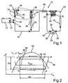
- Fig. 1 schematically shows a cooling arrangement 10 for cooling an electric unit 12, which is presently designed as a lithium-ion battery of a motor vehicle not shown in detail.
- the electric unit 12 as a fuel cell or the like under load heat-releasing aggregate or as a result of a be formed externally heat input heatable, temperature-sensitive aggregate.
- an evaporator 14 is arranged on this, which is integrated into a refrigeration circuit 16 of the cooling arrangement 10.
- a condenser 18 is furthermore arranged, by means of which a refrigerant circulating in the refrigeration circuit 16 is to be liquefied.
- a collecting device 20 for collecting the liquefied by means of the condenser 18 refrigerant is arranged downstream of the condenser 18.
- a presently designed as a submersible pump device 22 is arranged in the collecting device and designed for conveying liquefied refrigerant.
- the refrigerant in the condenser 18 may be liquefied and supplied to the evaporator 14 in the liquefied state. If a temperature of the evaporator 14 is above the ambient temperature, then the liquid refrigerant in the evaporator 14 may partially or completely evaporate, flow back to the condenser 18 and be liquefied there again at least partially. For evaporating the liquid refrigerant in the evaporator 14, the heat of the electric power unit 12 is supplied to the evaporator 14 and the electric power unit 12 is cooled accordingly.
- the condenser 18, a compressor 24 is connected upstream in the refrigeration cycle 16.
- the vaporizer 14 is charged with liquefied refrigerant by means of the pumping device 22, the at least partially vaporized refrigerant coming from the vaporizer 14 flows past the compressor 24 via a bridging device 26 for bridging the compressor 24.
- the bridging device 26 has a check valve 28, which can be flowed through by the refrigerant when the evaporator 14 is acted upon by the pump device 22.
- the check valve 28 and the bridging device 26 are presently integrated in the compressor 24 formed.
- no more separation points 30 are provided in the refrigeration circuit 16, as are to be provided anyway when arranging the compressor 24. This is important in view of that an increase in a number of the separation points 30, which in the Fig. 1 upstream and downstream, respectively the components of the refrigeration cycle 16 are indicated schematically, could lead to a higher susceptibility to leakage of the cooling arrangement 10.
- a check valve 32 arranged in the collecting device 20 is arranged parallel to the pumping device 22, so that when the evaporator 14 is acted upon by the compressor 24, the pumping device 22 can be bridged.
- the compressor 24 is used in the present case for charging the evaporator 14 when a difference between the ambient temperature and the temperature present at the evaporator 14 is not sufficient for cooling the electric unit 12. In particular, at ambient temperatures of less than 20 ° C, however, a cooling of the electric unit 12 by means of the acted upon by the pumping device 22 with liquid refrigerant evaporator 14 is possible.
- the compressed, liquefied in the condenser 18 refrigerant is expanded by means of an evaporator 14 upstream expansion element 34.
- the expansion element 34 may be formed as a fixed throttle.
- a first shut-36 is to open in the refrigeration cycle 16, and thereby a bypass device 38 for bypassing the expansion element 34 release.
- the bypass device 38 can be shut off by means of the first shut-off device 36.
- a second shut-off device 40 which is connected upstream of the expansion element 34, can be opened.
- shut-off devices 36, 40 and the expansion element 34 may be integrally formed in a loading module 42, whereby a number of separation points 30 can be kept low.
- Fig. 1 the refrigeration cycle 16 to another evaporator 44, which is provided for cooling a passenger compartment of the motor vehicle.
- the further evaporator 44 is connected in parallel in the refrigeration cycle 16 to the evaporator 14 for cooling the electric unit 12.
- the refrigerant circulates in the refrigeration circuit 16 due to the operation of the compressor 24.
- the further evaporator 44 for cooling the passenger compartment of the motor vehicle is according to Fig. 1 preceded by a further expansion element 46, by means of which the compressed by means of the compressor 24, liquefied in the condenser 18 refrigerant is depressurized.
- the further expansion element 46 may be formed as a thermostatic expansion valve.
- the further expansion element 46 a further shut-off device 48 upstream, by means of which a flow through the further expansion element 46 is to be prevented.
- the further expansion element 46 and the upstream shut-off device 48 may also be formed integrally in the admission module 42. As a result, a number of separation points 30 in the refrigeration cycle 16 is further reduced.
- thermostatic expansion valve expansion element 46 is according to Fig. 1 associated with a temperature sensor 50, by means of which a temperature downstream of the further evaporator 44 can be detected.
- a pressure sensor 52 is arranged between the capacitor 18 and the collecting device 20.
- FIG. 1 shows Fig. 1 in that the compressor 24 is preceded by an internal heat exchanger 54, by means of which heat between the compressed refrigerant and the evaporators 14, 44 exiting refrigerant is exchangeable.
- an efficiency of the cooling arrangement 10 is increased.
- the further expansion element 46 upstream shut-off valve 48 can be omitted, especially if the example designed as a thermostatic expansion valve further expansion element 46 is in the presence of a small pressure difference upstream and downstream of the pumping device 22 in a closed position. Such a small, the expansion element 46 in a closed position transferring, pressure difference is present in the refrigeration circuit 16 given when the evaporator 14 is acted upon by means of the pumping device 22 with refrigerant.
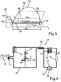
- Fig. 2 shows a pressure-enthalpy diagram, wherein on an ordinate logarithmically a pressure p of the refrigerant in the refrigeration circuit 16, and an ordinate an enthalpy h of the refrigerant are plotted.
- a trace 56 illustrates a state change in the refrigeration cycle according to FIG Fig. 1 Refrigerant when cooling the electric unit 12, wherein for acting on the evaporator 14 of the compressor 24 is operated.
- a phase boundary line 58 is drawn in which has a rising gradient up to a vertex 60 and a downward slope after vertex 60.
- the vertex 60 simultaneously represents a critical point, so that when the pressure assigned to the critical point p is exceeded, supercritical conditions are present.
- the refrigerant At pressures p below the critical point is according to Fig. 2 at comparatively low enthalpy values, the refrigerant is in the liquid state. In a region 62 delimited upward by the phase boundary line 58, there is a mixture of liquid and gaseous refrigerant. At relatively high enthalpy values of the refrigerant, the refrigerant is completely present as a gaseous phase.
- a vertex A of the contemplatnzugs 56 describes a state of the refrigerant in which it is present at comparatively low pressure P and with comparatively large enthalpy h at the entrance of the compressor 24.
- a corner B illustrates the state of the compressed by means of the compressor 24, gaseous refrigerant.
- the high-pressure refrigerant is isobaric liquefied.
- the liquefied state of the refrigerant is through the corner point C of the felicitnzugs 56 in Fig. 2 illustrated.
- the pressure p decreases of the refrigerant by a pressure difference .DELTA.p, which is to be applied when compressing the refrigerant from the compressor 24.
- FIG. 2 An in Fig. 2 indicated temperature line 64 illustrates a temperature T u of the ambient air. This is higher than a present at the electric power unit 12 temperature T Batt , which by a second temperature line 66 in Fig. 2 is shown.
- the refrigerant absorbs heat by evaporation of the liquid phase, its enthalpy changes isobaric in the Fig. 2 shown enthalpy difference .DELTA.h, which corresponds to a distance between the vertices D and A of the technicallynzugs 56.
- Fig. 2 It can be seen that for dissipating heat of the electric unit 12, that is to say for pressurizing the refrigerant with the enthalpy difference ⁇ h through the compressor 24, a comparatively high pressure change work corresponding to the pressure difference ⁇ p is used.
- Fig. 3 shows a trace 68 in the pressure-enthalpy diagram according to FIG Fig. 2 which illustrates a change in state of the refrigerant when the evaporator 14 is acted upon by means of the pump device 22.
- a temperature line 64 illustrative of the temperature T u of the ambient air is arranged below the temperature line 66, the temperature T u of the ambient air is thus lower than the temperature of the electric unit 12 cooled by the evaporator 14.
- the vertex C of the line 68 illustrates the state of FIG that of the liquid refrigerant present downstream of the condenser 18.
- the line 68 is how Fig. 3 can be seen completely within a limited by the temperature lines 64, 66 area.
- the amount of heat which can be withdrawn via the refrigerant to the electric unit 12 that is to say the enthalpy difference ⁇ h transferable to the refrigerant, is greater than the enthalpy difference ⁇ h, which in Fig. 2 is shown.
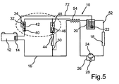
- Fig. 4 shows a further embodiment of a cooling arrangement 10, which differs from the in Fig. 1 in that the further evaporator 44 is preceded by an alternative further expansion element 70 which can be converted by driving into an open position.
- the alternative further expansion element 70 may be formed as an electrically controlled expansion valve, such as a solenoid valve. In a closed position of the further expansion element 70, the further expansion element 70 serves as a shut-off valve. In an adjustable by driving the further expansion element 70 open position of the further expansion element 70, the further expansion element 70 can be largely flowed through throttle free.
- This function of transferring the further expansion element 70 into the open position can be used if the air present in front of the further evaporator 44 has a higher temperature T L than the temperature T u of the ambient air.
- the air flowing into the further evaporator 44 in a climate box of the motor vehicle can be heated to temperatures of 5 ° K to 10 ° K by heat input from an internal combustion engine and / or exhaust system operated in particular under high load and / or by waste heat from electric motors, electronic components and the like be warmed to the temperature T u of the ambient air.
- This heat input can be increased again by a recirculation mode and / or strong sunlight.
- the heated air can be cooled in the air box to values just above the temperature T u of the ambient air by the pumping device 22, the throttle throttling applied to the other evaporator 44 with liquefied refrigerant.
- the Compressor 24 is not in operation.
- the passenger compartment of the motor vehicle can thus be cooled very efficiently and fuel-efficiently by operating the pumping device 22 when the temperature T U of the ambient air is lower than the temperature T L of the air before the further evaporator 44.
- Fig. 5 shows a further embodiment of a cooling arrangement 10, which substantially the in Fig. 1 shown embodiment of the cooling arrangement 10 corresponds. However, in the cooling arrangement 10 according to FIG Fig. 5 a bridging means 72 for bridging the inner heat exchanger 54 is provided.
- the bridging device 72 also bridges the expansion element 34 designed approximately as a fixed throttle, which is connected upstream of the evaporator 14.
- the according to Fig. 1 Check valve 32 arranged parallel to pumping device 22 in collecting device 20 is provided according to FIG Fig. 5 downstream of the expansion element 34 and upstream of a junction of the lock-up device 72 is arranged in the loading module 42.
- the shut-off device 40 assigned to the expansion element 34 is arranged downstream of the junction of the bridging device 72 in the loading module 42.
- the low enthalpy h in the liquefied refrigerant is particularly widely used to extract heat from the electric unit 12 during evaporation in the evaporator 14.
- the further evaporator 44 upstream components which according to Fig. 5 the formed as a thermostatic expansion valve further expansion element 46 with the upstream shut-off device 48 include, may be formed integrally in the admission module 42.
Landscapes
- Engineering & Computer Science (AREA)
- Manufacturing & Machinery (AREA)
- Chemical & Material Sciences (AREA)
- Chemical Kinetics & Catalysis (AREA)
- Electrochemistry (AREA)
- General Chemical & Material Sciences (AREA)
- Physics & Mathematics (AREA)
- Thermal Sciences (AREA)
- Mechanical Engineering (AREA)
- General Engineering & Computer Science (AREA)
- Life Sciences & Earth Sciences (AREA)
- Sustainable Development (AREA)
- Sustainable Energy (AREA)
- Air-Conditioning For Vehicles (AREA)
Abstract
Description
Die Erfindung betrifft eine Kühlanordnung zum Kühlen eines temperaturempfindlichen Aggregats, insbesondere eines Elektroaggregats, eines Kraftfahrzeugs, mit einem Kondensator zum Verflüssigen zumindest eines Teilvolumens eines Kältemittels in einem Kältekreislauf und mit einem stromabwärts des Kondensators angeordneten Verdampfer, welcher mit dem Kältemittel beaufschlagbar ist, und welchem Wärme des temperaturempfindlichen Aggregats, insbesondere des Elektroaggregats, zuführbar ist.The invention relates to a cooling arrangement for cooling a temperature-sensitive aggregate, in particular an electric unit, of a motor vehicle, with a condenser for liquefying at least a partial volume of a refrigerant in a refrigeration cycle and with a downstream of the condenser arranged evaporator, which is acted upon by the refrigerant, and which heat the temperature-sensitive aggregate, in particular of the electric unit, can be fed.
Als temperaturempfindliche Aggregate des Kraftfahrzeugs sind vorliegend Aggregate zu verstehen, welche beim Betreiben des Kraftfahrzeugs eine Erwärmung erfahren können, wobei die Erwärmung eine Funktionsfähigkeit des Aggregats zumindest vorübergehend beeinträchtigen kann. Hierbei kann die Erwärmung eine Folge des Betreibens des Aggregats selbst und/oder eine Folge eines externen Wärmeeintrags, etwa eines Eintrags von Abwärme eines Antriebsaggregats oder von Sonneneinstrahlung, sein.As a temperature-sensitive aggregates of the motor vehicle are in the present case to understand aggregates, which may experience a heating during operation of the motor vehicle, the heating may affect a functioning of the unit, at least temporarily. Here, the heating may be a consequence of the operation of the unit itself and / or a consequence of an external heat input, such as an entry of waste heat from a drive unit or sunlight.
Insbesondere in Hybridfahrzeugen und/oder Elektrofahrzeugen erzeugen Elektroaggregate wie Fahrbatterien, insbesondere Lithium-lonen-Batterien, Brennstoffzellen und dergleichen Wärme, wobei eine Menge an von dem Elektroaggregat erzeugter Wärme vom Lastzustand des Elektroaggregats abhängt. Lithium-lonen-Batterien sollten jedoch in einem Temperaturbereich von 20° C bis 30° C betrieben werden, um zu vermeiden, dass sich ihre Lebensdauer stark verkürzt.In particular, in hybrid vehicles and / or electric vehicles generate electric units such as traction batteries, in particular lithium-ion batteries, fuel cells and the like heat, with an amount of heat generated by the electric power unit depends on the load state of the electric unit. However, lithium-ion batteries should be operated in a temperature range of 20 ° C to 30 ° C to avoid a significant reduction in their service life.
Zum Kühlen des Elektroaggregats, insbesondere der Lithium-lonen-Batterie, kann an der Batterie ein Verdampfer einer zum Kühlen eines Fahrgastraums des Kraftfahrzeugs ausgelegten Kälteanlage angeordnet sein. Durch Beaufschlagen des Verdampfers mit einem in einem Kältekreislauf der Kälteanlage zirkulierenden Kältemittel und durch Zufuhren von Wärme des Elektroaggregats zu dem Verdampfer ist das Elektroaggregat kühlbar. Die Kälteanlage zum Kühlen des Fahrgastraums des Kraftfahrzeugs weist hierbei in üblicher Weise einen Verdichter zum Verdichten des gasförmigen Kältemittels, einen Kondensator zum Verflüssigen zumindest eines Teilvolumens des verdichteten Kältemittels sowie ein dem Verdampfer vorgeschaltetes Expansionsorgan zum Entspannen des verdichteten Kältemittels auf.For cooling the electric unit, in particular the lithium-ion battery, an evaporator of a refrigeration system designed for cooling a passenger compartment of the motor vehicle can be arranged on the battery. By applying the evaporator with a refrigerant circulating in a refrigeration circuit of the refrigeration system and by supplying heat of the electric aggregate to the evaporator, the electric aggregate can be cooled. The refrigeration system for cooling the Passenger compartment of the motor vehicle in this case has in the usual way a compressor for compressing the gaseous refrigerant, a condenser for liquefying at least a partial volume of the compressed refrigerant and an evaporator upstream expansion device for expanding the compressed refrigerant.
Als im Hinblick auf einen Energiebedarf der Kälteanlage ungünstig ist hierbei der Umstand anzusehen, dass auch bei kühlen Umgebungsbedingungen, bei welchen ein Kühlen des Fahrgastraums des Kraftfahrzeugs mittels der Kälteanlage nicht notwendig ist, der Verdichter der Kälteanlage betrieben werden muss, wenn von dem Elektroaggregat Wärme abgeführt und dem Verdampfer zugeführt werden soll.As unfavorable in view of an energy demand of the refrigeration system is the fact that even in cool ambient conditions in which a cooling of the passenger compartment of the motor vehicle by means of the refrigeration system is not necessary, the compressor of the refrigeration system must be operated when dissipated by the electric unit heat and to be supplied to the evaporator.
Die
Die
Dabei ist je nach Lastfall die vorgesehene Kühlung über die vorgeschlagene Kälteanlage trotz des zusätzlichen Pumpenbetriebs nur im Teillastbetrieb der Kälteanlage und somit mit schlechten Wirkungsgraden möglich.In this case, depending on the load case, the proposed cooling via the proposed refrigeration system despite the additional pump operation only in partial load operation of the refrigeration system and thus possible with poor efficiencies.
Alternativ kann, wie in der
Bei einer derartigen Kühlanordnung ist der Umstand als nachteilig anzusehen, dass beim Kühlen des Kühlmittels in dem separaten Kühlmittelkreislauf, insbesondere beim Nutzen des in den Kältekreislauf der Kälteanlage integrierten Verdampfers, eine ineffiziente Wärmetransportkette gegeben ist.In such a cooling arrangement, the circumstance is to be regarded as disadvantageous that an inefficient heat transport chain is given when cooling the coolant in the separate coolant circuit, in particular when using the integrated in the refrigeration cycle of the refrigeration system evaporator.
Des Weiteren ist es aus dem Stand der Technik bekannt, das Kühlmittel des separaten Kühlmittelkreislaufs, etwa eine Wasser-Glykol-Gemisch, kann bei niedrigen Umgebungstemperaturen mit Umgebungsluft zu kühlen. Beim Kühlen des separaten Kühlmittelkreislaufs mittels der Umgebungsluft des Kraftfahrzeugs kann der Kühler zum Kühlen des Kühlmittels in lufthydraulisch und thermisch ungünstiger Weise im Bereich anderer, etwa zum Kühlen eines Motorkühlmittels vorgesehener, Kühler oder in strömungstechnisch vergleichsweise ungünstiger Weise im Unterbodenbereich des Kraftfahrzeugs angeordnet sein.Furthermore, it is known from the prior art, the coolant of the separate coolant circuit, such as a water-glycol mixture, can cool at low ambient temperatures with ambient air. When cooling the separate coolant circuit by means of the ambient air of the motor vehicle, the radiator for cooling the coolant in air-hydraulic and thermally unfavorable manner in the other, for example, provided for cooling an engine coolant radiator or in fluidically relatively unfavorable manner be arranged in the underbody area of the motor vehicle.
Aufgabe der vorliegenden Erfindung ist es daher, eine Kühlanordnung der eingangs genannten Art zu schaffen, mittels welcher ein besonders effizientes Kühlen eines temperaturempfindlichen Aggregats eines Kraftfahrzeugs ermöglicht ist.Object of the present invention is therefore to provide a cooling arrangement of the aforementioned type, by means of which a particularly efficient cooling of a temperature-sensitive aggregate of a motor vehicle is possible.
Diese Aufgabe wird erfindungsgemäß durch eine Kühlanordnung mit den Merkmalen des Patentanspruchs 1 gelöst. Vorteilhafte Ausgestaltungen mit zweckmäßigen Weiterbildungen der Erfindung sind in den abhängigen Patentansprüchen angegeben.This object is achieved by a cooling arrangement with the features of claim 1. Advantageous embodiments with expedient developments of the invention are specified in the dependent claims.
Die erfindungsgemäße Kühlanordnung zum Kühlen eines temperaturempfindlichen Aggregats, insbesondere Elektroaggregats, eines Kraftfahrzeugs, mit einem Kondensator zum Verflüssigen zumindest eines Teilvolumens eines Kältemittels in einem Kältekreislauf und mit einem stromabwärts des Kondensators angeordneten Verdampfer, welcher mit dem Kältemittel beaufschlagbar und welchem Wärme des temperaturempfindlichen Aggregats, insbesondere Elektroaggregats, zuführbar ist, weist eine Pumpeinrichtung auf, mittels welcher der Verdampfer zumindest mit dem verflüssigten Teilvolumen des Kältemittels beaufschlagbar ist.The cooling arrangement according to the invention for cooling a temperature-sensitive unit, in particular electric unit, of a motor vehicle, with a condenser for liquefying at least one Partial volume of a refrigerant in a refrigeration cycle and arranged with a downstream of the condenser evaporator, which can be supplied with the heat and the heat of the temperature-sensitive unit, in particular electric unit, has a pumping means, by means of which the evaporator at least with the liquefied partial volume of the refrigerant acted upon is.
Die Pumpeinrichtung ist hierbei als Flüssigkeits-Pumpeinrichtung ausgebildet, welche zum Fördern des verflüssigten Teilvolumens des Kältemittels ausgelegt ist. Demgegenüber ist ein Verdichter eines Kältekreislaufs zum Verdichten und Fördern von gasförmigem Kältemittel ausgelegt, wobei ein Beaufschlagen des Verdichters mit flüssigem Kältemittel die Funktionsfähigkeit des Verdichters beeinträchtigt.The pumping device is in this case designed as a liquid pumping device, which is designed to convey the liquefied partial volume of the refrigerant. In contrast, a compressor of a refrigeration cycle is designed for compressing and conveying gaseous refrigerant, wherein a pressurization of the compressor with liquid refrigerant impairs the functioning of the compressor.
Der Kältekreislauf weist des weiteren stromabwärts des Verdampfers und stromaufwärts des Kondensators einen Verdichter zum Verdichten des Kältemittels auf, wobei dem Verdampfer ein Expansionselement zum Entspannen des verdichteten Kältemittels vorgeschaltet ist und wobei eine Überbrückungseinrichtung zum Überbrücken des Verdichters beim Beaufschlagen des Verdampfers mittels der Pumpeinrichtung vorgesehen ist.The refrigeration cycle further comprises downstream of the evaporator and upstream of the condenser, a compressor for compressing the refrigerant, wherein the evaporator is preceded by an expansion element for expanding the compressed refrigerant and wherein a bridging means is provided for bridging the compressor when the evaporator is acted upon by the pumping device.
Der Erfindung liegt die Erkenntnis zugrunde, dass insbesondere bei Temperaturen der das Kraftfahrzeugs umgebenden Umgebungsluft von weniger als 20° C Wärme des temperaturempfindlichen Aggregats mit besonders geringem Energieaufwand, nämlich lediglich dem zum Betreiben der Pumpeinrichtung notwendigen Energieaufwand, an die Umgebung abgeführt werden kann. Hierbei fördert die Pumpeinrichtung zumindest das mittels des Kondensators verflüssigte Teilvolumen des Kältemittels zu dem Verdampfer, wobei dem temperaturempfindlichen Aggregat Wärme in Form von latenter Wärme entzogen wird, welche zum Überführen des verflüssigten Kältemittels in einen gasförmigen Zustand aufzubringen ist. Dadurch ist ein besonders effizientes Kühlen des temperaturempfindlichen Aggregats, insbesondere Elektroaggregats, des Kraftfahrzeugs ermöglicht.The invention is based on the finding that especially at temperatures of the ambient air surrounding the motor vehicle of less than 20 ° C heat of the temperature-sensitive unit with particularly low energy consumption, namely only the energy required to operate the pumping device, can be dissipated to the environment. In this case, the pumping device conveys at least the partial volume of the refrigerant liquefied by means of the condenser to the evaporator, wherein heat is removed from the temperature-sensitive aggregate in the form of latent heat, which is to be applied to transfer the liquefied refrigerant into a gaseous state. This is a particularly efficient cooling of the temperature-sensitive aggregate, in particular electric unit, the motor vehicle allows.
Erst bei vergleichsweise hohen, also bei etwa über 25° C liegenden Umgebungstemperaturen, wenn also die Temperatur der Umgebungsluft die Temperatur des temperaturempfindlichen Aggregats übersteigt wird zum Verflüssigen des Kältemittels des Kondensators ein Beaufschlagen des Kondensators mit mittels des Verdichters verdichtetem Kältemittel erforderlich. Je nach Lastbedingungen des Elektroaggregats kann ein Kühlen des Elektroaggregats, insbesondere durch getaktetes Betreiben der Pumpeinrichtung, auch noch bei Umgebungstemperaturen von bis zu 27°C möglich sein, sofern der Kondensator gut von Umgebungsluft umströmt wird, etwa beim zügiger Fahrt des Kraftfahrzeugs.Only at comparatively high, ie at about 25 ° C lying ambient temperatures, that is, when the temperature of the ambient air exceeds the temperature of the temperature-sensitive unit is required to liquefy the refrigerant of the condenser urging the capacitor with compressed by means of the compressor refrigerant. Depending on the load conditions of the electric unit cooling of the electric unit, in particular by clocked operation of the pumping device, even at ambient temperatures of up to 27 ° C be possible, if the condenser is well surrounded by ambient air, such as the speedy drive of the motor vehicle.
Von Vorteil ist hierbei weiterhin, dass der Kondensator, welcher an lufthydraulisch besonders günstiger Position des Kraftfahrzeugs anordenbar ist, zur besonders effizienten Abfuhr von Wärme des temperaturempfindlichen Aggregats, insbesondere Elektroaggregats, nutzbar ist. Demgegenüber ist beim Kühlen des temperaturempfindlichen Aggregats, insbesondere Elektroaggregats, mittels des aus dem Stand der Technik bekannten separaten Kühlmittelkreislaufs der Kühler zum Kühlen des Kühlmittels in lufthydraulisch und thermisch ungünstiger Weise vor dem Kondensator angeordnet oder in einem thermisch und strömungstechnisch ungünstigen Bereich, etwa dem Unterboden des Kraftfahrzeugs, einem Radkasten oder dergleichen.The advantage here is further that the capacitor, which can be arranged on air-hydraulic particularly favorable position of the motor vehicle, for particularly efficient removal of heat of the temperature-sensitive unit, in particular electric unit, is available. In contrast, when cooling the temperature-sensitive unit, in particular electric unit, arranged by means of the known from the prior art separate coolant circuit for cooling the coolant in air-hydraulic and thermally unfavorable manner before the condenser or in a thermally and aerodynamically unfavorable area, such as the bottom of the Motor vehicle, a wheel arch or the like.
Durch ein Verzichten auf den separaten Kühlmittelkreislauf ist die Kühlanordnung besonders kompakt und kostengünstig auszubilden.By dispensing with the separate coolant circuit, the cooling arrangement is particularly compact and inexpensive to train.
Ebenso ist ein besonders effizientes Kühlen des temperaturempfindlichen Aggregats, insbesondere Elektroaggregats, dadurch ermöglicht, dass keine Wärmeübertragsverluste bei einem Wärmeübergang zwischen unterschiedlichen Wärmeübertragermedien, etwa dem Kältemittel und dem Kühlmittel, auftreten.Likewise, a particularly efficient cooling of the temperature-sensitive unit, in particular the electric unit, is made possible by the fact that no heat transfer losses occur during a heat transfer between different heat transfer media, such as the refrigerant and the coolant.
Darüber hinaus können Leitungen des Kältekreislaufs, welche das Kältemittel dem temperaturempfindlichen Aggregat, insbesondere dem Elektroaggregat, zuführen, einen wesentlich geringeren Querschnitt aufweise, als Leitungen des separaten, das Kühlmittel fördernden Kühlmittelkreislaufs. weniger effizientes Kühlen des temperaturempfindlichen Aggregats gegeben und es können Temperaturunterschiede innerhalb des gekühlten temperaturempfindlichen Aggregats von ca. 5° K auftreten.In addition, lines of the refrigeration cycle, which supply the refrigerant to the temperature-sensitive unit, in particular the electric unit, have a substantially smaller cross-section, as lines of the separate, the coolant conveying coolant circuit. given less efficient cooling of the temperature-sensitive aggregate and there may be temperature differences within the cooled temperature-sensitive aggregate of about 5 ° K.
Durch direktes Kühlen des temperaturempfindlichen Aggregats mittels des verdampfenden Kältemittels ist also ein Kühlen bei höheren Umgebungstemperaturen möglich als beim Nutzen des separaten Kühlmittelkreislaufs zum Kühlen.By directly cooling the temperature-sensitive unit by means of the evaporating refrigerant so cooling at higher ambient temperatures is possible than when using the separate coolant circuit for cooling.
In einer vorteilhaften Ausgestaltung der Erfindung ist die, insbesondere als Tauchpumpe ausgebildete, Pumpeinrichtung an einer, insbesondere stromabwärts des Kondensators angeordneten Sammeleinrichtung zum Sammeln des verflüssigten Teilvolumens des Kältemittels angeordnet. Dadurch weist die Pumpeinrichtung ein besonders gutes Anlaufverhalten auf. Die Pumpeinrichtung kann hierbei insbesondere in die Sammeleinrichtung integriert ausgebildet sein, so dass keine zusätzlich zu den zum Anordnen der Sammeleinrichtung in dem Kältekreislauf ohnehin vorzusehenden Trennstellen anzuordnen sind.In an advantageous embodiment of the invention, the pump device, in particular designed as a submersible pump, is arranged on a collecting device arranged in particular downstream of the condenser for collecting the liquefied partial volume of the refrigerant. As a result, the pumping device has a particularly good startup behavior. The pumping device may in this case be designed in particular integrated into the collecting device, so that no additional separating points to be provided in addition to the collecting device for arranging the collecting device in the refrigeration circuit are to be arranged.
Des Weiteren hat es sich als vorteilhaft gezeigt, wenn der Kältekreislauf stromabwärts des Verdampfers und stromaufwärts des Kondensators einen Verdichter zum Verdichten des Kältemittels aufweist, wobei dem Verdampfer ein Expansionselement zum Entspannen des verdichteten Kältemittels vorgeschaltet ist, und wobei eine Überbrückungseinrichtung zum Überbrücken des Verdichters beim Beaufschlagen des Verdampfers mittels der Pumpeinrichtung vorgesehen ist. Dadurch ist es ermöglicht, das temperaturempfindliche Aggregat zu kühlen, auch wenn vergleichsweise hohe, also etwa über 25° C liegende, Umgebungstemperaturen vorliegen, wenn also die Temperatur der Umgebungsluft die Temperatur des temperaturempfindlichen Aggregats übersteigt. In diesem Fall ist zum Verflüssigen des Kältemittels des Kondensators ein Beaufschlagen des Kondensators mit mittels des Verdichters verdichtetem Kältemittel erforderlich.Furthermore, it has proven to be advantageous if the refrigeration circuit downstream of the evaporator and upstream of the condenser comprises a compressor for compressing the refrigerant, wherein the evaporator is preceded by an expansion element for expanding the compressed refrigerant, and wherein a bridging device for bridging the compressor when applied the evaporator is provided by means of the pumping device. This makes it possible to cool the temperature-sensitive aggregate, even if comparatively high, so lying about about 25 ° C, ambient temperatures are present, so if the temperature of the ambient air exceeds the temperature of the temperature-sensitive aggregate. In this case, it is necessary to pressurize the condenser with refrigerant compressed by the compressor for liquefying the refrigerant of the condenser.
Die Überbrückungseinrichtung zum Überbrücken des Verdichters beim Beaufschlagen des Verdampfers mittels der Pumpeinrichtung kann in vorteilhafter Weise ein Rückschlagventil aufweisen, welches beim Beaufschlagen des Verdampfers mittels der Pumpeinrichtung von dem Kältemittel durchströmbar ist. Dadurch ist ein besonders einfaches, betriebsphasenabhängiges Schließen und/oder Öffnen der Überbrückungseinrichtung ermöglicht. Beim Betreiben des Verdichters zum Beaufschlagen des Kondensators mit verdichtetem Kältemittel schließt das Rückschlagventil die Überbrückungseinrichtung aufgrund des auf das Rückschlagventil wirkenden Drucks.The bridging device for bridging the compressor when the evaporator is acted upon by means of the pump device can advantageously have a check valve, which can be flowed through by the refrigerant when the evaporator is acted upon by the pump device. As a result, a particularly simple, operating phase-dependent closing and / or opening of the bridging device is made possible. When operating the compressor to pressurize the condenser with compressed refrigerant closes the Check valve the lock-up device due to the pressure acting on the check valve.
Es kann vorgesehen sein, dass mittels des Verdichters das Kältemittel mit einem Druck beaufschlagbar ist, welcher größer ist als ein beim Durchströmen des Kältemittels durch die Pumpeinrichtung maximal mittels der Pumpeinrichtung aufbringbarer Staudruck. Der Verdichter kann also ein Durchströmen der als Rückschlagventil wirkenden Pumpeinrichtung bewirken.It can be provided that by means of the compressor, the refrigerant can be acted upon with a pressure which is greater than a maximum upon application of the refrigerant by the pumping means can be applied by means of the pumping means ram pressure. The compressor can thus cause a flow through the acting as a check valve pumping device.
Ergänzend oder alternativ kann eine, insbesondere ein Rückschlagventil aufweisende Überbrückungseinrichtung zum Überbrücken der Pumpeinrichtung beim Beaufschlagen des Verdampfers mittels des Verdichters vorgesehen sein. Dadurch kann beim Betreiben des Verdichters das Kältemittel ungehindert an der Pumpeinrichtung vorbeiströmen. Weist die Überbrückungseinrichtung ein Rückschlagventil auf, so ist zudem ein Ausbilden einer Kurzschlussströmung in der Sammeleinrichtung beim Betreiben der Pumpeinrichtung verhindert.Additionally or alternatively, a bridging device, in particular having a check valve, can be provided for bridging the pump device when the evaporator is acted upon by the compressor. As a result, during operation of the compressor, the refrigerant can flow unhindered past the pump device. If the bridging device has a nonreturn valve, in addition a formation of a short-circuit flow in the collecting device during operation of the pumping device is prevented.
Von Vorteil ist es weiterhin, wenn eine von dem Kältemittel durchströmbare Umgehungseinrichtung zum Umgehen des Expansionselements vorgesehen ist, welche mittels einer ersten Absperreinrichtung absperrbar ist. Dadurch kann zumindest das verflüssigte Teilvolumen des Kältemittels drosselfrei und somit besonders effizient mittels der Pumpeinrichtung zu dem Verdampfer gefördert werden. Eine durch die Pumpeinrichtung zum Fördern des verflüssigten Teilvolumens des Kältemittels aufzubringenden Leistung kann dadurch minimiert werden. So kann bei außer Betrieb genommenen Verdichter mittels der Pumpeinrichtung bei einem Energieaufwand von weniger als 30 W das temperaturempfindliche Aggregat wirksam gekühlt werden, sofern die Temperatur der Umgebungsluft des Kraftfahrzeugs 20° C unterschreitet. Eine maximale Temperatur des Verdampfers, welchem Wärme des Elektroaggregats zugeführt wird, beträgt hierbei etwa 30° C. Ein Energiebedarf des Kraftfahrzeugs zum Kühlen des Elektroaggregats ist also besonders gering.It is furthermore advantageous if a bypass device through which the refrigerant can flow is provided for bypassing the expansion element, which can be shut off by means of a first shut-off device. As a result, at least the liquefied partial volume of the refrigerant can be conveyed throttle-free and therefore particularly efficient by means of the pumping device to the evaporator. A to be applied by the pumping device for conveying the liquefied partial volume of the refrigerant power can be minimized thereby. Thus, when taken out of service compressor by means of the pumping device with an energy consumption of less than 30 W, the temperature-sensitive unit can be effectively cooled, provided that the temperature of the ambient air of the motor vehicle falls below 20 ° C. A maximum temperature of the evaporator, which heat of the electric power unit is supplied, in this case is about 30 ° C. An energy requirement of the motor vehicle for cooling the electric unit is therefore particularly low.
In einer weiteren vorteilhaften Ausgestaltung der Erfindung ist dem Expansionselement eine zweite Absperreinrichtung zugeordnet, mittels welcher ein Durchströmen des Expansionselements zu unterbinden ist. Dadurch kann sichergestellt werden, dass das verflüssigte Kältemittel drosselfrei dem Verdampfer zuströmt, wenn die Pumpeinrichtung betrieben wird.In a further advantageous embodiment of the invention, the expansion element is associated with a second shut-off device, by means of which a flow through the expansion element is to be prevented. This can ensure that the liquefied refrigerant flows throttle-free to the evaporator when the pumping device is operated.
Selbstverständlich können die erste Absperreinrichtung und die zweite Absperreinrichtung beispielsweise in ein Drei-Wege-Ventil integriert ausgebildet sein.Of course, the first shut-off device and the second shut-off device may, for example, be integrated into a three-way valve.
Von Vorteil ist es weiterhin, wenn der Kältekreislauf einen weiteren Verdampfer zum Kühlen eines Fahrgastraums des Kraftfahrzeugs aufweist, welchem ein weiteres Expansionselement zum Entspannen des mittels des Verdichters verdichteten Kältemittels vorgeschaltet ist. Dadurch können beim Betreiben des Kältekreislaufs mittels des Verdichters, also bei vergleichsweise hohen Umgebungstemperaturen, der dem temperaturempfindlichen Aggregat zugeordnete Verdampfer und gleichzeitig der weitere Verdampfer mit dem verdichten Kältemittel beaufschlagt werden. So ist einerseits das effiziente Kühlen des Elektroaggregats gewährleistet und gleichzeitig mittels des Kältekreislaufs eine komfortable Kühlung des Fahrgastraums erreichbar.It is also advantageous if the refrigeration cycle has a further evaporator for cooling a passenger compartment of the motor vehicle, which is preceded by a further expansion element for releasing the refrigerant compressed by the compressor. As a result, during operation of the refrigeration cycle by means of the compressor, ie at comparatively high ambient temperatures, the evaporator associated with the temperature-sensitive unit and at the same time the further evaporator can be charged with the compressed refrigerant. Thus, on the one hand ensures the efficient cooling of the electric unit and at the same time by means of the refrigeration cycle comfortable cooling of the passenger compartment accessible.
Als weiter vorteilhaft hat es sich gezeigt, wenn mittels der Pumpeinrichtung in dem Kältekreislauf eine maximale Differenz zwischen einem stromaufwärts und stromabwärts der Pumpeinrichtung herrschenden Druck einstellbar ist, wobei das weitere Expansionselement mittels dieser maximalen Differenz in eine Schließstellung überführbar ist. Dadurch kann bei vergleichsweise kühlen Umgebungsbedingungen, wenn also kein Kühlen des Fahrgastraums notwendig und ausschließlich das temperaturempfindliche Aggregat zu kühlen ist, sichergestellt werden, dass das von der Pumpeinrichtung geförderte verflüssigte Teilvolumen des Kältemittels dem Verdampfer zugeführt wird, welcher dem temperaturempfindlichen Aggregat zugeordnet ist. Das weitere Expansionselement kann hierbei beispielsweise als thermostatisches Expansionsventil ausgebildet sein.As further advantageous, it has been shown that by means of the pumping device in the refrigeration circuit, a maximum difference between an upstream and downstream of the pumping device prevailing pressure is adjustable, wherein the further expansion element can be converted by means of this maximum difference in a closed position. As a result, at comparatively cool ambient conditions, ie when no cooling of the passenger compartment is necessary and only the temperature-sensitive unit is to be cooled, it can be ensured that the liquefied partial volume of the refrigerant conveyed by the pumping device is supplied to the evaporator, which is assigned to the temperature-sensitive unit. The further expansion element may in this case be designed, for example, as a thermostatic expansion valve.
Ergänzend, bevorzugt aber alternativ, kann dem weiteren Expansionselement eine weitere Absperreinrichtung zugeordnet sein, mittels welcher ein Durchströmen des weiteren Expansionselement zu unterbinden ist.In addition, but preferably as an alternative, the further expansion element may be associated with a further shut-off device, by means of which a flow through the further expansion element is to be prevented.
In einer weiteren vorteilhaften Ausgestaltung der Erfindung ist das weitere Expansionselement in eine Offenstellung überführbar, in welcher das weitere Expansionselement zumindest im Wesentlichen ungehindert von dem Kältemittel durchströmbar ist. Hierbei kann das weitere Expansionselement als elektrisch regelbares Expansionselement ausgebildet sein, so dass beim Beaufschlagen des Verdampfers mit dem verflüssigten Teilvolumen des Kältemittels das verflüssigte Kältemittel dem Verdampfer zum Kühlen des Fahrgastraums drosselfrei zugeführt werden kann.In a further advantageous embodiment of the invention, the further expansion element can be converted into an open position, in which the further expansion element can be flowed through by the refrigerant at least substantially unhindered. In this case, the further expansion element can be designed as an electrically controllable expansion element, so that when the evaporator is charged with the liquefied partial volume of the refrigerant, the liquefied refrigerant can be fed to the evaporator for throttling the passenger compartment in a throttle-free manner.
Dies ist insbesondere dann sinnvoll, wenn etwa bei einem Umluftbetrieb dem Fahrgastraum zuströmende Luft durch einen erhöhten Wärmeeintrag auf eine Temperatur über der Umgebungstemperatur erwärmt wird. Das Erwärmen kann hierbei durch Betreiben einer Verbrennungskraftmaschine des Kraftfahrzeugs, einen Gebläsemotor, und/oder weitere elektronische Bauteile bewirkt sein. Des Weiteren kann insbesondere das Betreiben einer Verbrennungskraftmaschine und/oder einer Abgasanlage unter hoher Last und/oder starke Sonneneinstrahlung zu einem Erwärmen der in dem Fahrgastraum zuströmenden Luft führen. Hierbei können sich vor dem zum Kühlen des Fahrgastraums vorgesehenen, weiteren Verdampfer Temperaturen einstellen, welche um deutlich mehr als 10° K über der Umgebungstemperatur des Kraftfahrzeugs liegen.This is particularly useful if, for example, in a recirculation mode the air flowing in the passenger compartment is heated by an increased heat input to a temperature above the ambient temperature. The heating can be effected in this case by operating an internal combustion engine of the motor vehicle, a fan motor, and / or other electronic components. Furthermore, in particular the operation of an internal combustion engine and / or an exhaust system under high load and / or strong sunlight can lead to a heating of the air flowing in the passenger compartment air. In this case, temperatures can be set in front of the further evaporator provided for cooling the passenger compartment which are much more than 10 ° K above the ambient temperature of the motor vehicle.
Durch Beaufschlagen des weiteren, zum Kühlen des Fahrgastraums vorgesehenen Verdampfers mittels der Pumpeinrichtung kann die über die Umgebungstemperatur erwärmte Luft so gekühlt werden, dass in den Fahrgastraum Luft mit einer komfortablen Temperatur einströmt, ohne dass der Verdichter in dem Kältekreislauf in Betrieb genommen zu werden braucht. Wird der Verdichter beim Betreiben des Verbrennungskraftmaschine mit angetrieben, so bringt ein Außer-Betrieb-Nehmen des Verdichters eine Kraftstoffeinsparung mit sich.By applying the further evaporator provided for cooling the passenger compartment by means of the pumping device, the air heated above the ambient temperature can be cooled so that air flows into the passenger compartment at a comfortable temperature without the compressor having to be put into operation in the refrigeration circuit. If the compressor is driven in the operation of the internal combustion engine with, so takes a decommissioning of the compressor fuel savings.
Des Weiteren hat es sich als vorteilhaft gezeigt, wenn das Expansionselement und die Absperreinrichtungen oder die Expansionselemente und die Absperreinrichtungen in ein Beaufschlagungsmodul integriert ausgebildet sind. Dadurch sind in dem Kältekreislauf weniger Trennstellen anzuordnen als bei einem getrennten Anschließen der einzelnen Komponenten in dem Kältekreislauf. Somit ist eine Anfälligkeit des Kältekreislaufs gegenüber Leckagen verringert.Furthermore, it has proven to be advantageous if the expansion element and the shut-off devices or the expansion elements and the shut-off devices are integrated into an admission module. As a result, fewer separation points are to be arranged in the refrigeration cycle than in a separate connection of the individual components in the refrigeration cycle. Thus, a susceptibility of the refrigeration cycle to leaks is reduced.
Sofern dem Verdichter ein innerer Wärmetauscher vorgeschaltet ist, mittels welchem Wärme zwischen dem verdichteten Kältemittel und dem aus dem Verdampfer austretenden Kältemittel austauschbar ist, weist der Kältekreislauf in vorteilhafter Weise eine beim Beaufschlagen des Verdampfers mittels der Pumpeinrichtung durchströmbare, insbesondere das Expansionselement überbrückende, Überbrückungseinrichtung zum Überbrücken des inneren Wärmetauschers auf. Dadurch kann ein Unterschied der Temperatur am Kondensator und an dem Verdampfer, welcher dem temperaturempfindlichen Aggregat zum Kühlen zugeordnet ist, besonders weitgehend ausgenutzt werden.If the compressor is preceded by an internal heat exchanger, by means of which heat between the compressed refrigerant and the refrigerant leaving the evaporator is interchangeable, the refrigeration cycle advantageously comprises a bypassing the evaporator by means of the pumping device durchströmbare, in particular the expansion element bridging, bridging means of the inner heat exchanger. As a result, a difference in the temperature at the condenser and at the evaporator, which is assigned to the temperature-sensitive unit for cooling, can be utilized to a large extent.
Die für die erfindungsgemäße Kühlanordnung beschriebenen bevorzugten Ausführungsformen und Vorteile gelten auch für das erfindungsgemäße Verfahren zum Kühlen eines Elektroaggregats eines Kraftfahrzeugs.The preferred embodiments and advantages described for the cooling arrangement according to the invention also apply to the method according to the invention for cooling an electric power unit of a motor vehicle.
Weitere Vorteile, Merkmale und Einzelheiten der Erfindung ergeben sich aus der nachfolgenden Beschreibung bevorzugter Ausführungsbeispiele sowie anhand der Zeichnungen, in welchen gleiche oder funktionsgleiche Elemente mit identischen Bezugszeichen versehen sind. Dabei zeigen:
- Fig. 1
- ein erstes Ausführungsbeispiel einer Kühlanordnung zum Kühlen eines Elektroaggregats eines Kraftfahrzeugs, wobei mittels einer Pumpeinrichtung ein mittels eines Kondensators verflüssigtes Kältemittel zu einem Verdampfer zu fördern ist, welchem Wärme des Elektroaggregats zuführbar ist;
- Fig. 2
- ein Druck-Enthalpie-Diagramm zum Veranschaulichen eines Verfahrens zum Kühlen des Elektroaggregats mittels eines in der Kühlanordnung gemäß
Fig. 1 angeordneten Verdichters; - Fig. 3
- ein Druck-Enthalpie-Diagramm zum Veranschaulichen eines Kühlvorgangs beim Kühlen des Elektroaggregats mittels der Pumpeinrichtung gemäß
Fig. 1 ; - Fig. 4
- eine Kühlanordnung zum Kühlen des Elektroaggregats sowie von Luft in einem Klimakasten, über welchen die Luft einem Fahrgastraum des Kraftfahrzeugs zuführbar ist, gemäß einem zweiten Ausführungsbeispiel; und
- Fig. 5
- eine Kühlanordnung zum Kühlen des Elektroaggregats gemäß einem dritten Ausführungsbeispiel.
- Fig. 1
- a first embodiment of a cooling arrangement for cooling an electric power unit of a motor vehicle, wherein by means of a pumping means a liquefied by means of a condenser refrigerant is to be conveyed to an evaporator, which heat of the electric unit can be supplied;
- Fig. 2
- a pressure-enthalpy diagram for illustrating a method for cooling the electric power unit by means of a in the cooling arrangement according to
Fig. 1 arranged compressor; - Fig. 3
- a pressure-enthalpy diagram for illustrating a cooling process during cooling of the electric unit by means of the pumping device according to
Fig. 1 ; - Fig. 4
- a cooling arrangement for cooling the electric unit and of air in a climate box, via which the air can be fed to a passenger compartment of the motor vehicle, according to a second embodiment; and
- Fig. 5
- a cooling arrangement for cooling the electric unit according to a third embodiment.
Zum Kühlen des Elektroaggregats 12 ist an diesem ein Verdampfer 14 angeordnet, welcher in einen Kältekreislauf 16 der Kühlanordnung 10 eingebunden ist. In dem Kältekreislauf 16 ist des Weiteren ein Kondensator 18 angeordnet, mittels welchem ein in dem Kältekreislauf 16 zirkulierendes Kältemittel zu verflüssigen ist.For cooling the
Stromabwärts des Kondensators 18 ist eine Sammeleinrichtung 20 zum Sammeln des mittels des Kondensators 18 verflüssigten Kältemittels angeordnet. Eine vorliegend als Tauchpumpe ausgebildete Pumpeinrichtung 22 ist in der Sammeleinrichtung angeordnet und zum Fördern von verflüssigtem Kältemittel ausgelegt.Downstream of the
Insbesondere bei Umgebungstemperaturen von weniger als 20° C kann das Kältemittel in dem Kondensator 18 verflüssigt und in verflüssigtem Zustand dem Verdampfer 14 zugeführt werden. Liegt eine Temperatur des Verdampfers 14 über der Umgebungstemperatur, so kann das flüssige Kältemittel in dem Verdampfer 14 teilweise oder komplett verdampfen, dem Kondensator 18 wieder zuströmen und dort wieder zumindest teilweise verflüssigt werden. Zum Verdampfen des flüssigen Kältemittels in dem Verdampfer 14 wird dem Verdampfer 14 hierbei die Wärme des Elektroaggregats 12 zugeführt und das Elektroaggregat 12 entsprechend gekühlt.In particular, at ambient temperatures of less than 20 ° C, the refrigerant in the
Wie in
Die Überbrückungseinrichtung 26 weist ein Rückschlagventil 28 auf, welches beim Beaufschlagen des Verdampfers 14 mittels der Pumpeinrichtung 22 von dem Kältemittel durchströmbar ist. Das Rückschlagventil 28 und die Überbrückungseinrichtung 26 sind vorliegend in den Verdichter 24 integriert ausgebildet. Somit sind infolge des Vorsehens der Überbrückungseinrichtung 26 mit dem Rückschlagventil 28 nicht mehr Trennstellen 30 in dem Kältekreislauf 16 vorzusehen, als beim Anordnen des Verdichters 24 ohnehin vorzusehen sind. Dies ist im Hinblick darauf von Bedeutung, dass eine Erhöhung einer Anzahl der Trennstellen 30, welche in der
Ein in der Sammeleinrichtung 20 angeordnetes Rückschlagventil 32 ist parallel zu der Pumpeinrichtung 22 angeordnet, so dass beim Beaufschlagen des Verdampfers 14 mittels des Verdichters 24 die Pumpeinrichtung 22 überbrückbar ist.A
Der Verdichter 24 wird vorliegend zum Beaufschlagen des Verdampfers 14 herangezogen, wenn eine Differenz zwischen der Umgebungstemperatur und der am Verdampfer 14 vorliegenden Temperatur nicht zum Kühlen des Elektroaggregats 12 ausreichend ist. Insbesondere bei Umgebungstemperaturen von weniger als 20° C ist jedoch ein Kühlen des Elektroaggregats 12 mittels des von der Pumpeinrichtung 22 mit flüssigem Kältemittel beaufschlagten Verdampfers 14 ermöglicht.The
Beim Beaufschlagen des Verdampfers 14 mit Kältemittel mittels des Verdichters 24 wird das verdichtete, in den Kondensator 18 verflüssigte Kältemittel mittels eines dem Verdampfer 14 vorgeschalteten Expansionselements 34 entspannt. Das Expansionselement 34 kann als Fixdrossel ausgebildet sein.When charging the
Damit beim Beaufschlagen des Verdampfers 14 mit dem verflüssigten Kältemittel aus der Sammeleinrichtung 20 mittels der Pumpeinrichtung 22 das verflüssigte Kältemittel drosselfrei dem Verdampfer 14 zugeführt werden kann, ist eine erste Absperreinrichtung 36 in dem Kältekreislauf 16 zu öffnen, und dadurch eine Umgehungseinrichtung 38 zum Umgehen des Expansionselements 34 freizugeben.Thus, when the
Soll hingegen der Verdampfer 14 mit entspanntem Kältemittel beaufschlagt werden, ist also der Verdichter 24 in Betrieb, so ist die Umgehungseinrichtung 38 mittels der ersten Absperreinrichtung 36 absperrbar. Gleichzeitig kann eine zweite Absperreinrichtung 40, welche dem Expansionselement 34 vorgeschaltet ist, geöffnet werden.If, on the other hand, the
Selbstverständlich können die Absperreinrichtungen 36, 40 und das Expansionselement 34 in ein Beaufschlagungsmodul 42 integriert ausgebildet sein, wodurch eine Anzahl an Trennstellen 30 gering gehalten werden kann.Of course, the shut-off
Gemäß
Beim Betreiben der Kühlanordnung 10 zum Kühlen des Fahrgastraums und zum gleichzeitigen Kühlen des Elektroaggregats 12, also bei vergleichsweise hohen Umgebungstemperaturen, zirkuliert das Kältemittel in dem Kältekreislauf 16 aufgrund des Betreibens des Verdichters 24.When operating the
Dem weiteren Verdampfer 44 zum Kühlen des Fahrgastraums des Kraftfahrzeugs ist gemäß
Gemäß dem in
Dem als thermostatisches Expansionsventil ausgebildeten Expansionselement 46 ist gemäß
Des Weiteren ist in
Darüber hinaus zeigt
Das dem weiteren Expansionsorgan 46 vorgeschaltete Absperrventil 48 kann entfallen, insbesondere wenn das beispielsweise als thermostatisches Expansionsventil ausgelegte weitere Expansionselement 46 sich bei Vorliegen einer geringen Druckdifferenz stromaufwärts und stromabwärts der Pumpeinrichtung 22 in einer Schließstellung befindet. Eine solche geringe, das Expansionselement 46 in eine Schließstellung überführende, Druckdifferenz ist vorliegend in dem Kältekreislauf 16 gegeben, wenn der Verdampfer 14 mittels der Pumpeinrichtung 22 mit Kältemittel beaufschlagt wird.The
Ein Linienzug 56 veranschaulicht eine Zustandsänderung des sich in dem Kältekreislauf gemäß
Bei Drücken p unterhalb des kritischen Punkts liegt gemäß
Ein Eckpunkt A des Linienzugs 56 beschreibt einen Zustand des Kältemittels, in welchem es bei vergleichsweise niedrigem Druck P und mit vergleichsweise großer Enthalpie h am Eingang des Verdichters 24 vorliegt. Ein Eckpunkt B veranschaulicht den Zustand des mittels des Verdichters 24 verdichteten, gasförmigen Kältemittels.A vertex A of the
Im Kondensator 18 und in dem diesem nachgeschalteten inneren Wärmetauscher 54 wird das unter hohem Druck stehende Kältemittel isobar verflüssigt. Der verflüssigte Zustand des Kältemittels ist durch den Eckpunkt C des Linienzugs 56 in
Eine in
In dem Verdampfer 14 bzw. 44 und in dem inneren Wärmetauscher 54 nimmt das Kältemittel durch Verdampfen der flüssigen Phase Wärme auf, seine Enthalpie ändert sich isobar um eine in der
Hierbei ist eine die Temperatur Tu der Umgebungsluft veranschaulichende Temperaturlinie 64 unterhalb der Temperaturlinie 66 angeordnet, die Temperatur Tu der Umgebungsluft ist also niedriger als die Temperatur des mittels des Verdampfers 14 gekühlten Elektroaggregats 12. Der Eckpunkt C des Linienzugs 68 veranschaulicht den Zustand des nach dem des stromabwärts des Kondensators 18 vorliegenden, flüssigen Kältemittels. Mittels der Pumpeinrichtung 22 wird ein Druck des flüssigen Kältemittels minimal, um die in
Beim Überführen des flüssigen Kältemittels in gasförmiges Kältemittel durch Wärmeaufnahme von dem Elektroaggregat 12 in dem Verdampfer 14 ändert sich die Enthalpie h des Kältemittels um eine vergleichweise große Enthalpiedifferenz Δh. Das beim Eckpunkt B, also stromabwärts des Verdampfers 14 vollständig gasförmig vorliegende Kältemittel wird mittels des Kondensators 18 verflüssigt, was in
Der Linienzug 68 liegt, wie
Wie aus
Das alternative weitere Expansionselement 70 kann als elektrisch geregeltes Expansionsventil, etwa als Magnetventil ausgebildet sein. In einer Schließstellung des weiteren Expansionselements 70 dient das weitere Expansionselement 70 als Absperrventil. In einer durch Ansteuern des weiteren Expansionselements 70 einstellbaren Offenstellung des weiteren Expansionselements 70 ist das weitere Expansionselement 70 weitgehend drosselfrei durchströmbar.The alternative
Diese Funktion des Überführens des weiteren Expansionselements 70 in die Offenstellung kann genutzt werden, wenn die vor dem weiteren Verdampfer 44 vorliegende Luft eine höhere Temperatur TL aufweist, als die Temperatur Tu der Umgebungsluft. Beispielsweise kann die dem weiteren Verdampfer 44 in einem Klimakasten des Kraftfahrzeugs zuströmende Luft durch Wärmeeintrag von einer insbesondere unter hoher Last betriebenen Verbrennungskraftmaschine und/oder Abgasanlage und/oder durch Abwärme von Elektromotoren, Elektronikkomponenten und dergleichen auf Temperaturen von 5° K bis 10° K über der Temperatur Tu der Umgebungsluft erwärmt sein. Dieser Wärmeeintrag kann durch einen Umluftbetrieb und/oder starke Sonneneinstrahlung nochmals erhöht sein.This function of transferring the
In diesem Fall kann die erwärmte Luft im Klimakasten auf Werte knapp oberhalb der Temperatur Tu der Umgebungsluft abgekühlt werden, indem die Pumpeinrichtung 22 den weiteren Verdampfer 44 drosselfrei mit verflüssigtem Kältemittel beaufschlagt. Der Verdichter 24 ist hierbei nicht in Betrieb. Der Fahrgastraum des Kraftfahrzeugs kann also sehr effizient und kraftstoffsparend durch Betreiben der Pumpeinrichtung 22 gekühlt werden, wenn die Temperatur TU der Umgebungsluft niedriger ist als die Temperatur TL der Luft vor dem weiteren Verdampfer 44.In this case, the heated air can be cooled in the air box to values just above the temperature T u of the ambient air by the
Die Überbrückungseinrichtung 72 überbrückt auch das etwa als Fixdrossel ausgebildete Expansionselement 34, welches dem Verdampfer 14 vorgeschaltet ist. Das gemäß
Die dem Expansionselement 34 zugeordnete Absperreinrichtung 40 ist stromabwärts der Einmündung der Überbrückungseinrichtung 72 in dem Beaufschlagungsmodul 42 angeordnet.The shut-off
Durch Umgehen des inneren Wärmetauschers 54 mittels der Überbrückungseinrichtung 72 ist die niedrige Enthalpie h in dem verflüssigten Kältemittel besonders weitgehend nutzbar, um dem Elektroaggregat 12 beim Verdampfen in dem Verdampfer 14 Wärme zu entziehen.By bypassing the
Selbstverständlich können die dem weiteren Verdampfer 44 vorgeschalteten Komponenten, welche gemäß
Claims (14)
- Cooling arrangement for cooling a temperature-sensitive assembly, in particular an electric assembly (12), of a motor vehicle, comprising a condenser (18) for liquefying at least a part of the volume of a refrigerant in a refrigerant circuit (16), an evaporator (14) sited downstream of the condenser (18), to which the refrigerant can be applied and to which the heat of the temperature-sensitive assembly, in particular the electric assembly (12), can be supplied, and a pumping device (22), wherein the refrigerant circuit (16) is provided with a compressor (24) for compressing the refrigerant downstream of the evaporator (14) and upstream of the condenser (18) and wherein an expansion element (34) for expanding the compressed refrigerant is provided upstream of the evaporator (14), wherein at least the liquefied part of the refrigerant volume can be applied to the evaporator (14) by means of the pumping device,
characterised in that
a bridging device (26) is provided for bridging the compressor (24) while the evaporator (14) is pressurised by means of the pumping device (22). - Cooling arrangement according to claim 1,
characterised in that
the pumping device (22) which is in particular designed as a submersible pump, is located at a collecting device (20) for collecting the liquefied part of the refrigerant volume, which is in particular located downstream of the condenser. - Cooling arrangement according to claim 1 or 2,
characterised in that
the bridging device (26) comprises a check valve (28) through which the refrigerant can flow while the evaporator (14) is pressurised by means of the pumping device (22). - Cooling arrangement according to claim 3,
characterised in that
by means of the compressor (24) a pressure can be applied to the refrigerant which is higher than a maximum back pressure which can be generated by the pumping device (22) as the refrigerant flows through the pumping device (22). - Cooling arrangement according to claim 3 or 4,
characterised in that
a bridging device, in particular comprising a check valve (32), is provided for bridging the pumping device (22) while the evaporator (14) is pressurised by means of the compressor (24). - Cooling arrangement according to any of claims 3 to 5,
characterised in that
a bypass device (38) through which refrigerant can flow is provided for bypassing the expansion element (34), which bypass device can be closed by a first shut-off device (36). - Cooling arrangement according to any of claims 3 to 6,
characterised in that
a second shut-off device (40) by means of which any flow through the expansion element (34) can be prevented is assigned to the expansion element (34). - Cooling arrangement according to any of claims 3 to 7,
characterised in that
the refrigerant circuit (16) comprises a further evaporator (44) for cooling an occupant cell of the motor vehicle, upstream of which is provided a further expansion element (46, 70) for expanding the refrigerant compressed by means of the compressor (24). - Cooling arrangement according to claim 8,
characterised in that
by means of the pumping device (22) a maximum difference between a pressure prevailing upstream and downstream of the pumping device (22) can be set in the refrigerant circuit (16), wherein the expansion element (46) can be moved into a closed position by means of this maximum difference. - Cooling arrangement according to claim 8 or 9,
characterised in that
a further shut-off device (48) by means of which any flow through the further expansion element (46) can be prevented is assigned to the further expansion element (46). - Cooling arrangement according to any of claims 8 to 10,
characterised in that
the further expansion element (70) can be moved into an open position in which the refrigerant can flow through the further expansion element (70) in an at least substantially unimpeded manner. - Cooling arrangement according to claims 6, 7 and 11
characterised in that
the expansion element (34) and the shut-off devices (36, 40) or the expansion elements (34, 46, 70) and the shut-off devices (36, 40, 48) are integrated to form a pressurisation module (42). - Cooling arrangement according to any of claims 3 to 12,
characterised in that
an internal heat exchanger (54), by means of which heat can be exchanged between the compressed refrigerant and the refrigerant discharged from the evaporator (14, 44), is assigned to the compressor (24). - Cooling arrangement according to claim 13,
characterised in that
the refrigerant circuit (16) comprises a bridging device (72), through which refrigerant can flow while the evaporator (14, 44) by is pressurised by means of the pumping device (22) and which in particular bridges the expansion element (34), for bridging the internal heat exchanger (54).
Applications Claiming Priority (3)
| Application Number | Priority Date | Filing Date | Title |
|---|---|---|---|
| DE102008019816 | 2008-04-19 | ||
| DE102008035216A DE102008035216A1 (en) | 2008-04-19 | 2008-07-29 | Cooling arrangement and method for cooling a temperature-sensitive aggregate of a motor vehicle |
| PCT/EP2009/001286 WO2009127292A1 (en) | 2008-04-19 | 2009-02-24 | Cooling arrangement and method for cooling a temperature-sensitive assembly of a motor vehicle |
Publications (2)
| Publication Number | Publication Date |
|---|---|
| EP2265453A1 EP2265453A1 (en) | 2010-12-29 |
| EP2265453B1 true EP2265453B1 (en) | 2011-08-24 |
Family
ID=41078772
Family Applications (1)
| Application Number | Title | Priority Date | Filing Date |
|---|---|---|---|
| EP09733539A Revoked EP2265453B1 (en) | 2008-04-19 | 2009-02-24 | Cooling arrangement and method for cooling a temperature-sensitive assembly of a motor vehicle |
Country Status (6)
| Country | Link |
|---|---|
| US (1) | US20110108242A1 (en) |
| EP (1) | EP2265453B1 (en) |
| JP (1) | JP5395890B2 (en) |
| AT (1) | ATE521491T1 (en) |
| DE (1) | DE102008035216A1 (en) |
| WO (1) | WO2009127292A1 (en) |
Cited By (1)
| Publication number | Priority date | Publication date | Assignee | Title |
|---|---|---|---|---|
| DE102022117709A1 (en) | 2022-07-15 | 2024-01-18 | Bayerische Motoren Werke Aktiengesellschaft | Method for operating a temperature control device of a motor vehicle and temperature control device for a motor vehicle |
Families Citing this family (23)
| Publication number | Priority date | Publication date | Assignee | Title |
|---|---|---|---|---|
| DE102009023394A1 (en) * | 2009-05-29 | 2010-12-30 | Airbus Deutschland Gmbh | Improved refrigeration device, in particular for aircraft |
| JP5320419B2 (en) * | 2011-02-04 | 2013-10-23 | 株式会社日本自動車部品総合研究所 | Cooling system |
| JP5755490B2 (en) * | 2011-04-18 | 2015-07-29 | トヨタ自動車株式会社 | Cooling system |
| FR2974327B1 (en) * | 2011-04-20 | 2014-02-28 | Valeo Systemes Thermiques | THERMAL CONDITIONING DEVICE OF A MOTOR VEHICLE |
| JP2012245857A (en) * | 2011-05-26 | 2012-12-13 | Nippon Soken Inc | Cooling apparatus, and method and device for controlling the same |
| FR2976224B1 (en) * | 2011-06-08 | 2013-05-31 | Valeo Systemes Thermiques | THERMAL CONDITIONING SYSTEM OF A CABINET AND AN ELECTRIC BATTERY |
| JP5798402B2 (en) * | 2011-08-01 | 2015-10-21 | トヨタ自動車株式会社 | Cooling system |
| JP5940778B2 (en) * | 2011-08-08 | 2016-06-29 | トヨタ自動車株式会社 | Cooling system |
| DE102011053256A1 (en) * | 2011-09-05 | 2013-03-07 | Dr. Ing. H.C. F. Porsche Aktiengesellschaft | Refrigeration circuit for use in a motor vehicle |
| JP2013061099A (en) | 2011-09-12 | 2013-04-04 | Toyota Motor Corp | Heat exchange apparatus and method for controlling heat exchange apparatus |
| JP5989328B2 (en) * | 2011-11-17 | 2016-09-07 | トヨタ自動車株式会社 | Heat exchanger |
| US9233594B2 (en) | 2012-02-23 | 2016-01-12 | Toyota Jidosha Kabushiki Kaisha | Cooling device and vehicle equipped with the same, and control method for cooling device |
| WO2013125006A1 (en) * | 2012-02-23 | 2013-08-29 | トヨタ自動車株式会社 | Cooling device and vehicle mounted with same, and method for controlling cooling device |
| FR2987886A3 (en) * | 2012-03-06 | 2013-09-13 | Renault Sa | Air conditioning device for electric vehicle, has reversible heat pump cooling battery of vehicle through heat transfer fluid and being placed between passenger and engine compartments, where pump has exchanger placed in front of vehicle |
| US8950201B2 (en) * | 2012-03-30 | 2015-02-10 | Trane International Inc. | System and method for cooling power electronics using heat sinks |
| KR102552112B1 (en) * | 2016-07-11 | 2023-07-10 | 한온시스템 주식회사 | Heat pump system for vehicle |
| FR3065325A1 (en) * | 2017-04-14 | 2018-10-19 | Valeo Systemes Thermiques | DEVICE FOR THERMALLY MANAGING A BATTERY PACK |
| DE102017116981A1 (en) * | 2017-07-27 | 2019-01-31 | Lion Smart Gmbh | Temperature control device for a temperature control of a battery system, battery system and method for tempering and / or extinguishing a battery system |
| CN108638787B (en) * | 2018-05-09 | 2022-01-04 | 贾宏涛 | Water circulation type heat energy comprehensive utilization and heat management system for electric automobile |
| CN110783939A (en) * | 2018-07-26 | 2020-02-11 | 深圳市瑞能实业股份有限公司 | Intelligent energy management system and general management system |
| ES2889698B2 (en) * | 2020-06-24 | 2023-04-28 | Seat Sa | Refrigeration system of at least one element to be refrigerated for a vehicle |
| CN113488717A (en) * | 2021-06-08 | 2021-10-08 | 同济大学 | Atomization cooling method and device for vehicle soft package lithium ion power battery |
| CN114094139B (en) * | 2022-01-18 | 2022-04-22 | 武汉海亿新能源科技有限公司 | Fuel cell system with multi-level thermal management control |
Family Cites Families (16)
| Publication number | Priority date | Publication date | Assignee | Title |
|---|---|---|---|---|
| US4434624A (en) * | 1981-03-27 | 1984-03-06 | Lockheed Corporation | Energy-efficient all-electric ECS for aircraft |
| US4599873A (en) * | 1984-01-31 | 1986-07-15 | Hyde Robert E | Apparatus for maximizing refrigeration capacity |
| JPH04251163A (en) * | 1990-12-06 | 1992-09-07 | Nippondenso Co Ltd | Car air conditioner |
| US5626025A (en) * | 1991-03-08 | 1997-05-06 | Hyde; Robert E. | Liquid pressure amplification with bypass |
| CA2298373A1 (en) * | 2000-02-11 | 2001-08-11 | Joseph Antoine Michel Grenier | Cooling system with enhanced free cooling |
| JP4540812B2 (en) * | 2000-08-11 | 2010-09-08 | 株式会社Nttファシリティーズ | air conditioner |
| JP4352604B2 (en) * | 2000-09-29 | 2009-10-28 | 三菱電機株式会社 | Air conditioner |
| DE10128164A1 (en) | 2001-06-09 | 2002-12-12 | Behr Gmbh & Co | Vehicle cooling system for a temperature-increasing device and method for cooling the temperature-increasing device |
| NO320664B1 (en) * | 2001-12-19 | 2006-01-16 | Sinvent As | System for heating and cooling vehicles |
| DE10201741A1 (en) * | 2002-01-18 | 2003-08-07 | Daimler Chrysler Ag | Vehicle with air conditioning and a heat source |
| US7096683B2 (en) * | 2003-09-12 | 2006-08-29 | Ford Global Technologies, Llc | Vehicle cooling system |
| JP2005090862A (en) * | 2003-09-17 | 2005-04-07 | Toyota Motor Corp | Cooling system |
| DE10343225B3 (en) * | 2003-09-18 | 2005-04-14 | Webasto Ag | System for heating and cooling an interior of a vehicle |
| JP2006216303A (en) * | 2005-02-02 | 2006-08-17 | Denso Corp | Cooling structure of heat radiating unit |
| FR2905309B1 (en) * | 2006-08-30 | 2015-03-27 | Peugeot Citroen Automobiles Sa | AIR CONDITIONING SYSTEM FOR A MOTOR VEHICLE WITH SECONDARY CIRCUIT FOR FEEDING THE BATTERY |
| JP2008055990A (en) * | 2006-08-30 | 2008-03-13 | Calsonic Kansei Corp | Vehicular battery cooling system |
-
2008
- 2008-07-29 DE DE102008035216A patent/DE102008035216A1/en not_active Withdrawn
-
2009
- 2009-02-24 JP JP2011504333A patent/JP5395890B2/en not_active Expired - Fee Related
- 2009-02-24 US US12/988,605 patent/US20110108242A1/en not_active Abandoned
- 2009-02-24 WO PCT/EP2009/001286 patent/WO2009127292A1/en active Application Filing
- 2009-02-24 EP EP09733539A patent/EP2265453B1/en not_active Revoked
- 2009-02-24 AT AT09733539T patent/ATE521491T1/en active
Cited By (1)
| Publication number | Priority date | Publication date | Assignee | Title |
|---|---|---|---|---|
| DE102022117709A1 (en) | 2022-07-15 | 2024-01-18 | Bayerische Motoren Werke Aktiengesellschaft | Method for operating a temperature control device of a motor vehicle and temperature control device for a motor vehicle |
Also Published As
| Publication number | Publication date |
|---|---|
| US20110108242A1 (en) | 2011-05-12 |
| EP2265453A1 (en) | 2010-12-29 |
| DE102008035216A1 (en) | 2009-10-22 |
| JP5395890B2 (en) | 2014-01-22 |
| WO2009127292A1 (en) | 2009-10-22 |
| ATE521491T1 (en) | 2011-09-15 |
| JP2011518301A (en) | 2011-06-23 |
Similar Documents
| Publication | Publication Date | Title |
|---|---|---|
| EP2265453B1 (en) | Cooling arrangement and method for cooling a temperature-sensitive assembly of a motor vehicle | |
| EP2519415B1 (en) | Climate control system for a vehicle and method for controlling temperature | |
| DE102019109796A1 (en) | A heat flow management device and method of operating a heat flow management device | |
| DE102011118162B4 (en) | Combined refrigeration system and heat pump and method for operating the system with function-dependent refrigerant transfer within the refrigerant circuit | |
| DE102016121362A1 (en) | Device for distributing heat in a motor vehicle and method for operating the device | |
| EP3697635B1 (en) | Method for operating a coolant circuit and vehicle air-conditioning system | |
| DE102015122721B4 (en) | Air conditioning system of a motor vehicle and method for operating the air conditioning system | |
| DE102012022564B4 (en) | Motor vehicle with an air conditioning device and operating method therefor | |
| DE102020107111A1 (en) | Heat pump arrangement for vehicles with a vehicle cabin heating circuit and a battery heating circuit | |
| DE102009035329A1 (en) | Method and device for operating a vehicle | |
| DE102017100591B3 (en) | Refrigerant circuit, in particular for motor vehicles with electric or hybrid drive and method for operating the refrigerant circuit | |
| DE102020117471B4 (en) | Heat pump arrangement with indirect battery heating for battery-operated motor vehicles and method for operating a heat pump arrangement | |
| DE102017204116B4 (en) | Refrigeration system of a vehicle with a refrigerant circuit that can be operated as a refrigeration circuit for refrigeration and as a heat pump circuit for heating | |
| DE102011075284A1 (en) | Method for conditioning a heat / cold storage and vehicle with a heat / cold storage | |
| EP2287952B1 (en) | Tempering device | |
| DE102018114762B4 (en) | Method for operating an air conditioning system in a motor vehicle | |
| DE102018207049A1 (en) | Refrigeration system for a vehicle having a heat pump function having a refrigerant circuit | |
| DE102018113687A1 (en) | Apparatus and method for cooling battery cell modules | |
| DE102018214211A1 (en) | Device and method for tempering an electrical energy store for a motor vehicle | |
| DE102012212227A1 (en) | Cooling system, particularly vehicle air conditioning system, has heat transmission device with one or multiple thermoelectric elements, particularly Peltier elements, which are connected with subcooling path | |
| DE102017124811A1 (en) | An air conditioning system for conditioning the air of a passenger compartment of a motor vehicle and method for operating the air conditioning system | |
| DE102017213973A1 (en) | Method for operating a refrigeration system of a vehicle having a refrigerant circuit having a cooling and heating function | |
| DE102017201686A1 (en) | Method for operating a refrigeration system of a vehicle | |
| WO2023280507A1 (en) | Refrigeration circuit, and heat management system and motor vehicle having a refrigeration circuit of this type | |
| DE102020111511A1 (en) | Refrigeration system and heat pump arrangement for battery-operated vehicles and method for operating a refrigeration system and heat pump arrangement |
Legal Events
| Date | Code | Title | Description |
|---|---|---|---|
| PUAI | Public reference made under article 153(3) epc to a published international application that has entered the european phase |
Free format text: ORIGINAL CODE: 0009012 |
|
| 17P | Request for examination filed |
Effective date: 20100922 |
|
| AK | Designated contracting states |
Kind code of ref document: A1 Designated state(s): AT BE BG CH CY CZ DE DK EE ES FI FR GB GR HR HU IE IS IT LI LT LU LV MC MK MT NL NO PL PT RO SE SI SK TR |
|
| AX | Request for extension of the european patent |
Extension state: AL BA RS |
|
| GRAP | Despatch of communication of intention to grant a patent |
Free format text: ORIGINAL CODE: EPIDOSNIGR1 |
|
| DAX | Request for extension of the european patent (deleted) | ||
| GRAS | Grant fee paid |
Free format text: ORIGINAL CODE: EPIDOSNIGR3 |
|
| GRAA | (expected) grant |
Free format text: ORIGINAL CODE: 0009210 |
|
| AK | Designated contracting states |
Kind code of ref document: B1 Designated state(s): AT BE BG CH CY CZ DE DK EE ES FI FR GB GR HR HU IE IS IT LI LT LU LV MC MK MT NL NO PL PT RO SE SI SK TR |
|
| REG | Reference to a national code |
Ref country code: GB Ref legal event code: FG4D Free format text: NOT ENGLISH |
|
| REG | Reference to a national code |
Ref country code: CH Ref legal event code: EP |
|
| REG | Reference to a national code |
Ref country code: IE Ref legal event code: FG4D Free format text: LANGUAGE OF EP DOCUMENT: GERMAN |
|
| REG | Reference to a national code |
Ref country code: DE Ref legal event code: R096 Ref document number: 502009001200 Country of ref document: DE Effective date: 20111020 |
|
| REG | Reference to a national code |
Ref country code: NL Ref legal event code: VDEP Effective date: 20110824 |
|
| LTIE | Lt: invalidation of european patent or patent extension |
Effective date: 20110824 |
|
| PG25 | Lapsed in a contracting state [announced via postgrant information from national office to epo] |
Ref country code: NL Free format text: LAPSE BECAUSE OF FAILURE TO SUBMIT A TRANSLATION OF THE DESCRIPTION OR TO PAY THE FEE WITHIN THE PRESCRIBED TIME-LIMIT Effective date: 20110824 Ref country code: SE Free format text: LAPSE BECAUSE OF FAILURE TO SUBMIT A TRANSLATION OF THE DESCRIPTION OR TO PAY THE FEE WITHIN THE PRESCRIBED TIME-LIMIT Effective date: 20110824 Ref country code: FI Free format text: LAPSE BECAUSE OF FAILURE TO SUBMIT A TRANSLATION OF THE DESCRIPTION OR TO PAY THE FEE WITHIN THE PRESCRIBED TIME-LIMIT Effective date: 20110824 Ref country code: HR Free format text: LAPSE BECAUSE OF FAILURE TO SUBMIT A TRANSLATION OF THE DESCRIPTION OR TO PAY THE FEE WITHIN THE PRESCRIBED TIME-LIMIT Effective date: 20110824 Ref country code: IS Free format text: LAPSE BECAUSE OF FAILURE TO SUBMIT A TRANSLATION OF THE DESCRIPTION OR TO PAY THE FEE WITHIN THE PRESCRIBED TIME-LIMIT Effective date: 20111224 Ref country code: LT Free format text: LAPSE BECAUSE OF FAILURE TO SUBMIT A TRANSLATION OF THE DESCRIPTION OR TO PAY THE FEE WITHIN THE PRESCRIBED TIME-LIMIT Effective date: 20110824 Ref country code: PT Free format text: LAPSE BECAUSE OF FAILURE TO SUBMIT A TRANSLATION OF THE DESCRIPTION OR TO PAY THE FEE WITHIN THE PRESCRIBED TIME-LIMIT Effective date: 20111226 Ref country code: NO Free format text: LAPSE BECAUSE OF FAILURE TO SUBMIT A TRANSLATION OF THE DESCRIPTION OR TO PAY THE FEE WITHIN THE PRESCRIBED TIME-LIMIT Effective date: 20111124 |
|
| PG25 | Lapsed in a contracting state [announced via postgrant information from national office to epo] |
Ref country code: GR Free format text: LAPSE BECAUSE OF FAILURE TO SUBMIT A TRANSLATION OF THE DESCRIPTION OR TO PAY THE FEE WITHIN THE PRESCRIBED TIME-LIMIT Effective date: 20111125 Ref country code: PL Free format text: LAPSE BECAUSE OF FAILURE TO SUBMIT A TRANSLATION OF THE DESCRIPTION OR TO PAY THE FEE WITHIN THE PRESCRIBED TIME-LIMIT Effective date: 20110824 Ref country code: SI Free format text: LAPSE BECAUSE OF FAILURE TO SUBMIT A TRANSLATION OF THE DESCRIPTION OR TO PAY THE FEE WITHIN THE PRESCRIBED TIME-LIMIT Effective date: 20110824 Ref country code: LV Free format text: LAPSE BECAUSE OF FAILURE TO SUBMIT A TRANSLATION OF THE DESCRIPTION OR TO PAY THE FEE WITHIN THE PRESCRIBED TIME-LIMIT Effective date: 20110824 Ref country code: CY Free format text: LAPSE BECAUSE OF FAILURE TO SUBMIT A TRANSLATION OF THE DESCRIPTION OR TO PAY THE FEE WITHIN THE PRESCRIBED TIME-LIMIT Effective date: 20110824 |
|
| REG | Reference to a national code |
Ref country code: IE Ref legal event code: FD4D |
|
| PG25 | Lapsed in a contracting state [announced via postgrant information from national office to epo] |
Ref country code: SK Free format text: LAPSE BECAUSE OF FAILURE TO SUBMIT A TRANSLATION OF THE DESCRIPTION OR TO PAY THE FEE WITHIN THE PRESCRIBED TIME-LIMIT Effective date: 20110824 Ref country code: IE Free format text: LAPSE BECAUSE OF FAILURE TO SUBMIT A TRANSLATION OF THE DESCRIPTION OR TO PAY THE FEE WITHIN THE PRESCRIBED TIME-LIMIT Effective date: 20110824 Ref country code: CZ Free format text: LAPSE BECAUSE OF FAILURE TO SUBMIT A TRANSLATION OF THE DESCRIPTION OR TO PAY THE FEE WITHIN THE PRESCRIBED TIME-LIMIT Effective date: 20110824 |
|
| PG25 | Lapsed in a contracting state [announced via postgrant information from national office to epo] |
Ref country code: EE Free format text: LAPSE BECAUSE OF FAILURE TO SUBMIT A TRANSLATION OF THE DESCRIPTION OR TO PAY THE FEE WITHIN THE PRESCRIBED TIME-LIMIT Effective date: 20110824 Ref country code: IT Free format text: LAPSE BECAUSE OF FAILURE TO SUBMIT A TRANSLATION OF THE DESCRIPTION OR TO PAY THE FEE WITHIN THE PRESCRIBED TIME-LIMIT Effective date: 20110824 Ref country code: RO Free format text: LAPSE BECAUSE OF FAILURE TO SUBMIT A TRANSLATION OF THE DESCRIPTION OR TO PAY THE FEE WITHIN THE PRESCRIBED TIME-LIMIT Effective date: 20110824 |
|
| PLBI | Opposition filed |
Free format text: ORIGINAL CODE: 0009260 |
|
| PLAX | Notice of opposition and request to file observation + time limit sent |
Free format text: ORIGINAL CODE: EPIDOSNOBS2 |
|
| PG25 | Lapsed in a contracting state [announced via postgrant information from national office to epo] |
Ref country code: DK Free format text: LAPSE BECAUSE OF FAILURE TO SUBMIT A TRANSLATION OF THE DESCRIPTION OR TO PAY THE FEE WITHIN THE PRESCRIBED TIME-LIMIT Effective date: 20110824 |
|
| 26 | Opposition filed |
Opponent name: RITTAL GMBH & CO. KG Effective date: 20120524 |
|
| REG | Reference to a national code |
Ref country code: DE Ref legal event code: R026 Ref document number: 502009001200 Country of ref document: DE Effective date: 20120524 |
|
| BERE | Be: lapsed |
Owner name: DAIMLER A.G. Effective date: 20120228 |
|
| PG25 | Lapsed in a contracting state [announced via postgrant information from national office to epo] |
Ref country code: MC Free format text: LAPSE BECAUSE OF NON-PAYMENT OF DUE FEES Effective date: 20120229 |
|
| PLBB | Reply of patent proprietor to notice(s) of opposition received |
Free format text: ORIGINAL CODE: EPIDOSNOBS3 |
|
| PG25 | Lapsed in a contracting state [announced via postgrant information from national office to epo] |
Ref country code: BE Free format text: LAPSE BECAUSE OF NON-PAYMENT OF DUE FEES Effective date: 20120228 |
|
| PG25 | Lapsed in a contracting state [announced via postgrant information from national office to epo] |
Ref country code: MK Free format text: LAPSE BECAUSE OF FAILURE TO SUBMIT A TRANSLATION OF THE DESCRIPTION OR TO PAY THE FEE WITHIN THE PRESCRIBED TIME-LIMIT Effective date: 20110824 |
|
| PG25 | Lapsed in a contracting state [announced via postgrant information from national office to epo] |
Ref country code: ES Free format text: LAPSE BECAUSE OF FAILURE TO SUBMIT A TRANSLATION OF THE DESCRIPTION OR TO PAY THE FEE WITHIN THE PRESCRIBED TIME-LIMIT Effective date: 20111205 |
|
| PG25 | Lapsed in a contracting state [announced via postgrant information from national office to epo] |
Ref country code: BG Free format text: LAPSE BECAUSE OF FAILURE TO SUBMIT A TRANSLATION OF THE DESCRIPTION OR TO PAY THE FEE WITHIN THE PRESCRIBED TIME-LIMIT Effective date: 20111124 |
|
| PG25 | Lapsed in a contracting state [announced via postgrant information from national office to epo] |
Ref country code: MT Free format text: LAPSE BECAUSE OF FAILURE TO SUBMIT A TRANSLATION OF THE DESCRIPTION OR TO PAY THE FEE WITHIN THE PRESCRIBED TIME-LIMIT Effective date: 20110824 |
|
| REG | Reference to a national code |
Ref country code: CH Ref legal event code: PL |
|
| PG25 | Lapsed in a contracting state [announced via postgrant information from national office to epo] |
Ref country code: CH Free format text: LAPSE BECAUSE OF NON-PAYMENT OF DUE FEES Effective date: 20130228 Ref country code: LI Free format text: LAPSE BECAUSE OF NON-PAYMENT OF DUE FEES Effective date: 20130228 |
|
| PG25 | Lapsed in a contracting state [announced via postgrant information from national office to epo] |
Ref country code: TR Free format text: LAPSE BECAUSE OF FAILURE TO SUBMIT A TRANSLATION OF THE DESCRIPTION OR TO PAY THE FEE WITHIN THE PRESCRIBED TIME-LIMIT Effective date: 20110824 |
|
| PG25 | Lapsed in a contracting state [announced via postgrant information from national office to epo] |
Ref country code: LU Free format text: LAPSE BECAUSE OF NON-PAYMENT OF DUE FEES Effective date: 20120224 |
|
| PGFP | Annual fee paid to national office [announced via postgrant information from national office to epo] |
Ref country code: FR Payment date: 20140226 Year of fee payment: 6 |
|
| PGFP | Annual fee paid to national office [announced via postgrant information from national office to epo] |
Ref country code: GB Payment date: 20140228 Year of fee payment: 6 |
|
| PG25 | Lapsed in a contracting state [announced via postgrant information from national office to epo] |
Ref country code: HU Free format text: LAPSE BECAUSE OF FAILURE TO SUBMIT A TRANSLATION OF THE DESCRIPTION OR TO PAY THE FEE WITHIN THE PRESCRIBED TIME-LIMIT Effective date: 20090224 |
|
| REG | Reference to a national code |
Ref country code: AT Ref legal event code: MM01 Ref document number: 521491 Country of ref document: AT Kind code of ref document: T Effective date: 20140224 |
|
| RDAF | Communication despatched that patent is revoked |
Free format text: ORIGINAL CODE: EPIDOSNREV1 |
|
| PG25 | Lapsed in a contracting state [announced via postgrant information from national office to epo] |
Ref country code: AT Free format text: LAPSE BECAUSE OF NON-PAYMENT OF DUE FEES Effective date: 20140224 |
|
| REG | Reference to a national code |
Ref country code: DE Ref legal event code: R064 Ref document number: 502009001200 Country of ref document: DE Ref country code: DE Ref legal event code: R103 Ref document number: 502009001200 Country of ref document: DE |
|
| PGFP | Annual fee paid to national office [announced via postgrant information from national office to epo] |
Ref country code: DE Payment date: 20150429 Year of fee payment: 7 |
|
| RDAG | Patent revoked |
Free format text: ORIGINAL CODE: 0009271 |
|
| STAA | Information on the status of an ep patent application or granted ep patent |
Free format text: STATUS: PATENT REVOKED |
|
| 27W | Patent revoked |
Effective date: 20150608 |
|
| GBPR | Gb: patent revoked under art. 102 of the ep convention designating the uk as contracting state |
Effective date: 20150608 |
|
| REG | Reference to a national code |
Ref country code: AT Ref legal event code: MA03 Ref document number: 521491 Country of ref document: AT Kind code of ref document: T Effective date: 20150608 |