EP2264553A2 - Ressort thermocompensé et son procédé de fabrication - Google Patents
Ressort thermocompensé et son procédé de fabrication Download PDFInfo
- Publication number
- EP2264553A2 EP2264553A2 EP10165641A EP10165641A EP2264553A2 EP 2264553 A2 EP2264553 A2 EP 2264553A2 EP 10165641 A EP10165641 A EP 10165641A EP 10165641 A EP10165641 A EP 10165641A EP 2264553 A2 EP2264553 A2 EP 2264553A2
- Authority
- EP
- European Patent Office
- Prior art keywords
- spring
- section
- metallic material
- forming
- outer layer
- Prior art date
- Legal status (The legal status is an assumption and is not a legal conclusion. Google has not performed a legal analysis and makes no representation as to the accuracy of the status listed.)
- Granted
Links
Images
Classifications
-
- F—MECHANICAL ENGINEERING; LIGHTING; HEATING; WEAPONS; BLASTING
- F16—ENGINEERING ELEMENTS AND UNITS; GENERAL MEASURES FOR PRODUCING AND MAINTAINING EFFECTIVE FUNCTIONING OF MACHINES OR INSTALLATIONS; THERMAL INSULATION IN GENERAL
- F16F—SPRINGS; SHOCK-ABSORBERS; MEANS FOR DAMPING VIBRATION
- F16F1/00—Springs
- F16F1/02—Springs made of steel or other material having low internal friction; Wound, torsion, leaf, cup, ring or the like springs, the material of the spring not being relevant
- F16F1/024—Covers or coatings therefor
-
- B—PERFORMING OPERATIONS; TRANSPORTING
- B21—MECHANICAL METAL-WORKING WITHOUT ESSENTIALLY REMOVING MATERIAL; PUNCHING METAL
- B21F—WORKING OR PROCESSING OF METAL WIRE
- B21F3/00—Coiling wire into particular forms
-
- G—PHYSICS
- G04—HOROLOGY
- G04B—MECHANICALLY-DRIVEN CLOCKS OR WATCHES; MECHANICAL PARTS OF CLOCKS OR WATCHES IN GENERAL; TIME PIECES USING THE POSITION OF THE SUN, MOON OR STARS
- G04B17/00—Mechanisms for stabilising frequency
- G04B17/20—Compensation of mechanisms for stabilising frequency
- G04B17/22—Compensation of mechanisms for stabilising frequency for the effect of variations of temperature
- G04B17/227—Compensation of mechanisms for stabilising frequency for the effect of variations of temperature composition and manufacture of the material used
-
- F—MECHANICAL ENGINEERING; LIGHTING; HEATING; WEAPONS; BLASTING
- F16—ENGINEERING ELEMENTS AND UNITS; GENERAL MEASURES FOR PRODUCING AND MAINTAINING EFFECTIVE FUNCTIONING OF MACHINES OR INSTALLATIONS; THERMAL INSULATION IN GENERAL
- F16F—SPRINGS; SHOCK-ABSORBERS; MEANS FOR DAMPING VIBRATION
- F16F2222/00—Special physical effects, e.g. nature of damping effects
- F16F2222/02—Special physical effects, e.g. nature of damping effects temperature-related
-
- Y—GENERAL TAGGING OF NEW TECHNOLOGICAL DEVELOPMENTS; GENERAL TAGGING OF CROSS-SECTIONAL TECHNOLOGIES SPANNING OVER SEVERAL SECTIONS OF THE IPC; TECHNICAL SUBJECTS COVERED BY FORMER USPC CROSS-REFERENCE ART COLLECTIONS [XRACs] AND DIGESTS
- Y10—TECHNICAL SUBJECTS COVERED BY FORMER USPC
- Y10T—TECHNICAL SUBJECTS COVERED BY FORMER US CLASSIFICATION
- Y10T29/00—Metal working
- Y10T29/49—Method of mechanical manufacture
- Y10T29/49609—Spring making
Definitions
- the invention relates to a balance spring - balance spring and more particularly such a spring whose thermoelastic coefficient is substantially zero and almost insensitive to magnetic fields.
- the thermoelastic coefficient (CTE) of a body represents the relative variation of Young's modulus of said body as a function of temperature.
- the document EP 1 039 352 discloses a coil spring of particular alloy whose outer surface comprises an oxide coating.
- the document discloses a spiral spring which is thermally compensated, that is to say that, in particular, its thermoelastic coefficient, also called the thermal coefficient of Young's modulus, remains substantially close to zero and whose sensitivity to magnetic fields is very low. .
- the spring is very difficult to implement which causes a scrap rate and a cost that are very high.
- the object of the present invention is to overcome all or part of the aforementioned drawbacks by proposing a thermocompensated springs balance springs whose implementation is simplified.
- thermocompensated sprung-balance spring comprising a section comprising a first metallic material, characterized in that at least one of the faces of the section comprises an outer layer comprising a second metallic material whose coefficient thermoelastic varies in the opposite direction to that of the first.
- the spring is very simple and can therefore use conventional materials which avoids complex manufacturing steps.
- the invention also relates to a timepiece comprising at least one spring according to one of the preceding variants.
- the spring can be obtained with materials in a very simple manner using controlled mechanical steps that allow a very low scrap rate.
- the shape of the spring can be obtained with a first material with a very good accuracy and then, using step (s) overmolding and / or veneer mastered a second material, obtain a thermocompensated spring very high quality while allowing a very low scrap rate.
- the invention relates to a thermocompensated spring for a timepiece control member of the balance spring type.
- the spring according to the invention uses materials that can be worked by conventional methods of shaping metals. In addition, the materials used are common and therefore cheap.
- thermoelastic coefficient of the spring is rendered substantially zero, that is to say a relative variation of the Young's modulus as a function of the substantially zero temperature.
- two metal materials are used in recovery, the respective thermoelastic coefficients vary in opposite directions in order to compensate for each other. It is therefore understood that if one of the materials has a positive thermoelastic coefficient, the second will have a negative one.
- the material with positive thermoelastic coefficient can cover the other or vice versa. Only the overlapping thickness is to be adapted according to that covered and, also, depending on the type of balance to globally compensate the balancing device - balance spring.
- the recovery of materials may be partial or total.
- at least two parallel or adjacent faces of the body section of the first material may be provided with the second material.
- the covering may be on all or part of the length of the body of the first material.
- each face may also comprise a material which is specific to it, that is to say not to comprise a single second material.
- at least one of the materials may be paramagnetic in order to render substantially null the influence of the spring magnetic fields.
- the spring uses the pair of stainless steel materials - alloy FeMn or stainless steel - alloy FeNi36 invar type.
- the material that covers the other does not necessarily matter.
- the core preferably uses said ferromagnetic material.
- the core preferably uses FeMn alloy (antiferromagnetic) or FeNi36 (ferromagnetic) and the outer layer, steel (antiferromagnetic). It will also be noted that this configuration also makes it possible to limit the oxidation of said spring.
- the invention can not be limited to stainless steel - FeMn alloy or stainless steel - FeNi36 alloy.
- the outer layer may comprise stainless steel and / or chromium and / or nickel and / or iron.
- the spring core may comprise niobium, NbZr alloy, CrMn alloy, FeMn alloy, FeNi36 alloy or AuPd alloy.
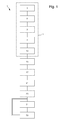
- Process 1 preferably comprises three main steps respectively for forming a body 11 with the aid of a first and second metal material secured to each other, reducing the body section and winding the body 21 in order to forming said spring.
- the forming step 11 generally comprises the phases 3, 5, 7 and 13 which are used for several embodiments.
- the body is formed from a bar and a tube.
- the bar of a first material is formed in the first phase 3 of the method 1.
- the tube of a second material is formed in a second phase of process 1 which can be carried out in parallel, before or after phase 3, the tube of a second material is formed.
- the bar is threaded into the tube.
- the section difference between the outside of the bar and the hollow of the tube is the smallest possible in order to limit their relative movements.
- phase 9 consists in carrying out a heat treatment of the bar and / or the tube in order to guarantee a space that is to say a difference in section between them as large as possible. It is therefore understood that heating to expand the tube and / or cooling to contract the bar are particularly envisaged.
- step 11 continues with the fourth phase 13 for securing the bar in the tube. So we understand that this first embodiment involves the covering over the entire section of the core of the first material.
- the phases 3 and 5 are always made to form a first and a second material.
- a third and a fourth phase 7, 13 the two materials are respectively brought against each other and then secured.
- the phase 13 may comprise a cold deformation and / or hot but also a bonding and / or welding.
- phase 3 is used to form a body of a first material and then, in a second phase 5, overmoulding or plating of a second material is performed. It is therefore understood that the phases 5, 7 and 13 can be performed at the same time, for example, by casting, electroplating or else by physical or chemical vapor deposition.
- the second step 15 is intended to reduce the section to the desired section of said spring.
- the largest section of the body can thus go from 5 to 100 mm at the end of step 11 to a final dimension of between 10 ⁇ m and 1 mm.
- steps 11, 15 and 21 are performed in a different order. Indeed, it is also possible to initially form only the first material according to steps 11, 15 and 21 and then to form the second material, as in the alternative above, during a phase 5 in which it is overmoulding and / or plating the first material with a second material.
- the shape of the spring would be given to the first material which can thus be obtained by a process of the drawing-rolling-strapping-fixing heat treatment type or by the deep reactive ionic type etching in a plate of the first material or by an electroforming process of the LIGA type (galvanic growth in a photosensitive resin mold).
- the first material can then be coated, as in the above alternative, by casting, electroplating or else by physical or chemical vapor deposition.
- the phase 13 and the step 15 are carried out in a single plastic deformation process.
- the deformation caused advantageously to secure the bar and the tube but also to reduce the section to that of the future spring.
- the deformation process is of the cold and / or hot type with, optionally, intermediate annealing phases in order to allow the material to deform to very small dimensions.
- step 15 may include cold deformations which may include drawing and / or drawing and / or forging and / or rolling and / or hammering.
- hot deformations may also be contemplated and may include drawing and / or forging and / or rolling and / or hammering.
- the method 1 may also comprise, following step 15, an additional step 17 intended to give the final shape of the section of the spring.
- step 17 the body section is changed to a polygonal section, such as, for example, a rectangular section.
- This step 17 is preferably carried out by rolling in order to obtain very advantageous dimensional tolerances.
- step 21 in which the body is wound to form the spring, for example, substantially shaped spiral.
- step 21 can terminate method 1.
- other variants are possible.
- an optional third step 23 may be provided after step 21 in order to lift the outer coil of the spring formed in step 21. Such a step 23 thus makes it possible to form a spiral spring of the Breguet type. According to the invention, the optional step 23 can also terminate the method 1.
- step 21 or 23 the method 1 can also continue with step 31 and / or 33.
- the method 1 may comprise the step 33 for performing a heat treatment in order to adjust the thermoelastic coefficient and the shape of the spring.
- step 33 can also terminate process 1.
- step 33 can be replaced or preceded by step 31 as illustrated by a single line at figure 1 .
- Step 31 is intended to effect a removal of material at the body after formation of the spring, ie after step 21 or 23 to adjust the thermoelastic coefficient of the spring.
- Stage 31 may for example comprise a machining and / or etching phase. According to the invention, it is understood that step 31 can also terminate process 1 and / or be used to determine the extra thickness to be removed on the next production.
Landscapes
- Engineering & Computer Science (AREA)
- Metallurgy (AREA)
- General Engineering & Computer Science (AREA)
- Mechanical Engineering (AREA)
- Manufacturing & Machinery (AREA)
- Physics & Mathematics (AREA)
- General Physics & Mathematics (AREA)
- Springs (AREA)
- Wire Processing (AREA)
Abstract
Description
- L'invention se rapporte à un ressort pour balancier - spiral et plus particulièrement un tel ressort dont le coefficient thermoélastique est sensiblement nul et quasiment insensible aux champs magnétiques. Le coefficient thermoélastique (CTE) d'un corps représente la variation relative du module d'Young dudit corps en fonction de la température.
- Il est connu, pour un mouvement mécanique d'horlogerie, de rechercher un écart de marche le plus faible possible. Cependant, il est très difficile d'y arriver en raison notamment de la sensibilité de l'ensemble balancier - spiral aux variations de température et de champs magnétiques.
- Le document
EP 1 039 352 divulgue un ressort-spiral en alliage particulier dont la surface externe comporte un revêtement d'oxyde. Le document divulgue un ressort-spiral qui est thermocompensé c'est-à-dire que, notamment, son coefficient thermoélastique, également appelé coefficient thermique du module d'Young, reste sensiblement proche de zéro et dont la sensibilité aux champs magnétiques est très faible. Cependant, le ressort est très difficile à mettre en oeuvre ce qui occasionne un taux de rebut et un prix de revient qui sont très élevés. - Le but de la présente invention est de pallier tout ou partie les inconvénients cités précédemment en proposant un ressort thermocompensé pour balancier - spiral dont la mise en oeuvre est simplifiée.
- A cet effet, l'invention se rapporte à un ressort thermocompensé pour balancier - spiral comportant une section comprenant un premier matériau métallique caractérisé en ce qu'au moins une des faces de la section comporte une couche externe comportant un deuxième matériau métallique dont le coefficient thermoélastique varie dans le sens opposé à celui du premier.
- Avantageusement selon l'invention, le ressort est très simple et peut donc utiliser des matériaux classiques ce qui évite des étapes de fabrication complexes.
- Conformément à d'autres caractéristiques avantageuses de l'invention :
- au moins deux faces parallèles ou au moins deux faces adjacentes ou toutes les faces de la section comportent ladite couche externe ;
- ladite couche externe court sur tout ou partie de la longueur du ressort ;
- au moins un des matériaux métalliques est paramagnétique ;
- le deuxième matériau est un acier inoxydable ;
- le premier matériau est un alliage FeMn ou un alliage FeNi36 du type invar ;
- la section comporte plusieurs couches externes différentes.
- L'invention se rapporte également à une pièce d'horlogerie comportant au moins un ressort conforme à l'une des variantes précédentes.
- Enfin, l'invention se rapporte à un procédé de fabrication d'un ressort pour une pièce d'horlogerie comportant les étapes suivantes :
- a) former un corps à l'aide d'un premier et d'un deuxième matériaux métalliques solidarisés, les premier et deuxième matériaux ayant des coefficients thermoélastiques qui varient en sens opposé ;
- b) diminuer la section du corps ;
- c) enrouler le corps afin de former ledit ressort.
- On comprend donc que le ressort peut être obtenu avec des matériaux de manière très simple à l'aide d'étapes mécaniques maîtrisées qui autorisent un très faible taux de rebut.
- Conformément à d'autres caractéristiques avantageuses de l'invention :
- le procédé comporte, entre l'étape b) et c), l'étape d) : modifier la section dudit corps en une section polygonale ;
- le procédé comporte, après l'étape c), l'étape e) : surélever la spire externe dudit ressort afin de former un ressort du type Breguet ;
- le procédé comporte l'étape f) : effectuer un enlèvement de matière du corps après la formation du ressort afin d'en ajuster le coefficient thermoélastique ;
- le procédé comporte l'étape finale g) : effectuer un traitement thermique après la formation du ressort afin d'ajuster le coefficient thermoélastique et la forme du ressort ;
- selon un premier mode de réalisation, l'étape a) comporte les phases h) : former une barre en un premier matériau métallique, i) : former un tube en un deuxième matériau métallique, j) : enfiler la barre dans le tube, k) : solidariser la barre dans le tube ;
- le procédé comporte, pendant l'étape j), une étape de refroidissement de la barre et/ou de chauffage du tube afin d'augmenter les espaces entre ces derniers dans le but de faciliter ladite étape j) ;
- à titre alternatif, l'étape a) comporte les phases de former une pièce en un premier matériau métallique, de solidariser un deuxième matériau métallique sur la pièce par surmoulage, placage, déformation à froid et/ou à chaud, collage et/ou soudage ;
- l'étape b) est réalisée par déformation à froid et/ou à chaud.
- la section externe du corps à la fin de l'étape a) est comprise entre 5 et 100 mm et, à la fin de l'étape c), comprise entre 10 µm et 1 mm ;
- au moins un des matériaux est paramagnétique.
- Une alternative consiste à proposer un procédé de fabrication d'un ressort pour balancier-spiral comportant les étapes suivantes :
- a')former un corps en forme de ressort à l'aide d'un premier matériau métallique ;
- b')solidariser un deuxième matériau métallique sur le corps par surmoulage et/ou placage, les premier et deuxième matériaux ayant des coefficients thermoélastiques qui varient en sens opposé.
- On comprend donc que la forme du ressort peut être obtenue avec un premier matériau avec une très bonne précision puis, à l'aide d'étape(s) de surmoulage et/ou de placage maîtrisées d'un deuxième matériau, obtenir un ressort thermocompensé de très grande qualité tout en autorisant un très faible taux de rebut.
- Conformément à d'autres caractéristiques avantageuses de l'alternative :
- l'étape a') est réalisée par un processus du type tréfilage - laminage
- estrapadage - traitement thermique de fixage ou par gravage du type ionique réactif profond dans une plaque dudit premier matériau métallique ou par un processus d'électroformage du type LIGA ;
- l'étape b') est réalisée par coulée, par galvanoplastie ou par dépôt physique ou chimique en phase vapeur ;
- le procédé comporte l'étape f) : effectuer un enlèvement de matière du corps après la formation du ressort afin d'en ajuster le coefficient thermoélastique ;
- le procédé comporte l'étape finale g) : effectuer un traitement thermique après la formation du ressort afin d'ajuster le coefficient thermoélastique et la forme du ressort ;
- au moins un des matériaux est paramagnétique.
- D'autres particularités et avantages ressortiront clairement de la description qui en est faite ci-après, à titre indicatif et nullement limitatif, en référence à l'unique figure représentant un schéma fonctionnel d'un procédé de fabrication d'un ressort selon l'invention.
- L'invention se rapporte à un ressort thermocompensé pour un organe régulateur de pièce d'horlogerie du type balancier - spiral. Le ressort selon l'invention utilise des matériaux susceptibles d'être travaillés par des méthodes classiques de mises en forme de métaux. De plus, les matériaux utilisés sont usuels et donc bon marché.
- Selon l'invention, le coefficient thermoélastique du ressort est rendu sensiblement nul, c'est-à-dire une variation relative du module d'Young en fonction de la température sensiblement nulle. Pour parvenir à ce but, on utilise deux matériaux métalliques en recouvrement dont les coefficients thermoélastiques respectifs varient en sens opposé afin de se compenser. On comprend donc que si un des matériaux possède un coefficient thermoélastique positif, le deuxième en possédera un négatif.
- De manière parfaitement équivalente, le matériau à coefficient thermoélastique positif peut recouvrir l'autre ou inversement. Seule l'épaisseur en recouvrement est à adapter en fonction de celle recouverte et, également, en fonction du type de balancier afin de globalement compenser l'organe régulateur balancier - spiral.
- Le recouvrement des matériaux peut être partiel ou total. Ainsi, notamment, au moins deux faces parallèles ou adjacentes de la section du corps du premier matériau peuvent être munies du deuxième matériau. De manière similaire, le recouvrement peut être sur tout ou partie de la longueur du corps du premier matériau. On comprend également que chaque face peut également comprendre un matériau qui lui est propre, c'est-à-dire ne pas comprendre un unique deuxième matériau. Enfin, au moins un des matériaux peut être paramagnétique afin de rendre sensiblement nul l'influence du ressort aux champs magnétiques.
- Préférentiellement, le ressort utilise le couple de matériaux acier inoxydable - alliage FeMn ou acier inoxydable - alliage FeNi36 du type invar. Le matériau qui recouvre l'autre n'a pas forcément d'importance. Cependant, si l'un des deux matériaux est ferromagnétique, l'âme utilise, de manière préférée, ledit matériau ferromagnétique. Aussi, pour les exemples ci-dessus, l'âme utilise préférentiellement l'alliage FeMn (antiferromagnétique) ou FeNi36 (ferromagnétique) et, la couche externe, l'acier (antiferromagnétique). On notera également que cette configuration permet également de limiter l'oxydation dudit ressort.
- Afin de calculer les épaisseurs respectives de l'âme (matériau 1) par rapport à la couche externe (matériau 2), on calcule le coefficient thermoélastique corrigé CTE' souhaité et éventuellement, le couple corrigé C' souhaité pour son adaptation avec un balancier selon les relations suivantes où les coefficients de dilatation sont jugés équivalents :


Où :

Et : - Ex est le module d'Young du matériau x ;
- CTEx est le coefficient thermoélastique du matériau x ;
- e est l'épaisseur de l'âme ;
- h est la hauteur de l'âme ;
- d est l'épaisseur de la couche externe.
- Bien entendu, l'invention ne saurait se limiter au couple acier inoxydable - alliage FeMn ou acier inoxydable - alliage FeNi36. Ainsi, il peut être envisagé d'autres couples. A titre d'exemple, la couche externe peut comporter de l'acier inoxydable et/ou du chrome et/ou du nickel et/ou du fer. De même, à titre d'exemple, l'âme du ressort peut comporter du niobium, de l'alliage NbZr, de l'alliage CrMn, de l'alliage FeMn, de l'alliage FeNi36 ou de l'alliage AuPd.
- Le procédé de fabrication 1 du ressort ci-dessus va maintenant être expliqué en référence à la
figure 1 . Le procédé 1 comporte préférentiellement trois étapes principales respectivement de formation 11 d'un corps à l'aide d'un premier et d'un deuxième matériaux métalliques solidarisés, de diminution 15 de la section du corps et d'enroulement 21 dudit corps afin de former ledit ressort. - L'étape de formation 11 comporte généralement les phases 3, 5, 7 et 13 qui sont utilisées pour plusieurs modes de réalisation. Selon un premier mode de réalisation, le corps est formé à partir d'une barre et d'un tube. Dans la première phase 3 du procédé 1, la barre d'un premier matériau est formée. Dans une deuxième phase 5 du procédé 1 qui peut être effectuée en parallèle, avant ou après la phase 3, le tube d'un deuxième matériau est formé. Puis dans une troisième phase 7, la barre est enfilée dans le tube. Préférentiellement, la différence de section entre l'extérieure de la barre et le creux du tube est la plus petite possible afin de limiter leurs déplacements relatifs.
- Ainsi afin de faciliter l'exécution de la phase 7, de manière préférée, une phase optionnelle 9, avant la phase 7, est prévue. La phase 9 consiste à effectuer un traitement thermique de la barre et/ou du tube afin de garantir un espace c'est-à-dire une différence de section entre ces derniers la plus grande possible. On comprend donc qu'un chauffage pour dilater le tube et/ou un refroidissement pour contracter la barre sont notamment envisagés. Après la phase 7, l'étape 11 poursuit avec la quatrième phase 13 destinée à solidariser la barre dans le tube. On comprend donc que ce premier mode de réalisation implique le recouvrement sur toute la section de l'âme du premier matériau.
- II est également envisagé de recouvrir seulement certaines faces, ainsi, dans un autre mode de réalisation, les phases 3 et 5 sont toujours faites pour former un premier et un deuxième matériaux. Dans une troisième et une quatrième phases 7, 13, les deux matériaux sont respectivement amenés l'un contre l'autre puis solidarisés. De manière non limitative, dans cet autre mode de réalisation, la phase 13 peut comprendre une déformation à froid et/ou à chaud mais également un collage et/ou un soudage.
- Bien entendu, d'autres étapes de formation 11 comportant plus ou moins de phases 3, 5, 7, 9, 13 sont également possibles. Ainsi, selon une alternative, la phase 3 est utilisée pour former un corps en un premier matériau puis, dans une seconde phase 5, il est opéré un surmoulage ou un placage d'un deuxième matériau. On comprend donc que les phases 5, 7 et 13 peuvent être réalisées en même temps, par exemple, par coulée, par galvanoplastie ou encore par dépôt physique ou chimique en phase vapeur.
- La deuxième étape 15 est destinée à diminuer la section jusqu'à la section voulue dudit ressort. A titre d'exemple, la section la plus grande du corps peut ainsi passer de 5 à 100 mm à la fin de l'étape 11 à une dimension finale comprise entre 10 µm et 1 mm.
- Il est également parfaitement envisageable que les étapes 11, 15 et 21 soient effectuées dans un ordre différent. En effet, il est possible également de former dans un premier temps uniquement le premier matériau selon les étapes 11, 15 et 21 puis former le deuxième matériau, comme dans l'alternative ci-dessus, lors d'une phase 5 dans laquelle il est opéré un surmoulage et/ou un placage du premier matériau par un deuxième matériau.
- A titre d'exemple, la forme du ressort serait donnée au premier matériau qui peut ainsi être obtenu par processus du type tréfilage - laminage - estrapadage - traitement thermique de fixage ou par gravage du type ionique réactif profond dans une plaque du premier matériau ou par un processus d'électroformage du type LIGA (croissance galvanique dans un moule en résine photosensible). Le premier matériau peut ensuite être revêtu, comme dans l'alternative ci-dessus, par coulée, par galvanoplastie ou encore par dépôt physique ou chimique en phase vapeur.
- De manière préférée pour le premier mode de réalisation de l'invention, la phase 13 et l'étape 15 sont réalisées en un processus unique de déformation plastique. Ainsi, la déformation occasionnée permet avantageusement de solidariser la barre et le tube mais également de diminuer la section à celle du futur ressort. De manière préférée, le processus de déformation est du type à froid et/ou à chaud avec, éventuellement, des phases intermédiaires de recuit afin d'autoriser la matière à se déformer jusqu'à de très petites dimensions.
- Ainsi pour tous les modes de réalisation, l'étape 15 peut comporter des déformations à froid qui peuvent comprendre du tréfilage et/ou de l'étirage et/ou du forgeage et/ou du laminage et/ou du martelage. De même, à titre d'exemple, des déformations à chaud peuvent également être envisagées et peuvent comprendre de l'étirage et/ou du forgeage et/ou du laminage et/ou du martelage.
- Préférentiellement, le procédé 1 peut comporter également, à la suite de l'étape 15, une étape supplémentaire 17 destinée à donner la forme finale de la section du ressort. Ainsi, dans l'étape 17, la section du corps est modifiée en une section polygonale, comme, par exemple, une section rectangulaire. Cette étape 17 est préférentiellement effectuée par laminage afin d'obtenir des tolérances dimensionnelles très avantageuses.
- Le procédé 1 est poursuivi avec l'étape 21 dans laquelle on enroule le corps afin de former le ressort, par exemple, sensiblement en forme de spirale. Selon l'invention, l'étape 21 peut terminer le procédé 1. Cependant, d'autres variantes sont possibles.
- Ainsi, une troisième étape optionnelle 23 peut être prévue après l'étape 21 afin de lever la spire externe du ressort formé lors de l'étape 21. Une telle étape 23 permet ainsi de former un ressort en spirale du type Breguet. Selon l'invention, l'étape optionnelle 23 peut également terminer le procédé 1.
- Cependant, après l'étape 21 ou 23, le procédé 1 peut également se poursuivre avec l'étape 31 et/ou 33. Ainsi, comme illustré à la
figure 1 en trait double, après l'étape 21 ou 23, le procédé 1 peut comporter l'étape 33 destinée à effectuer un traitement thermique dans le but d'ajuster le coefficient thermoélastique et la forme du ressort. Selon l'invention, l'étape 33 peut également terminer le procédé 1. - Néanmoins, l'étape 33 peut être remplacée ou précédée par l'étape 31 comme illustré par un trait simple à la
figure 1 . L'étape 31 est destinée à effectuer un enlèvement de matière au niveau du corps après la formation du ressort c'est-à-dire après l'étape 21 ou 23 afin d'ajuster le coefficient thermoélastique du ressort. L'étape 31 peut par exemple comporter une phase d'usinage et/ou d'attaque chimique. Selon l'invention, on comprend que l'étape 31 peut également terminer le procédé 1 et/ou être utilisée pour déterminer la surépaisseur à enlever sur la prochaine production. - Bien entendu, la présente invention ne se limite pas à l'exemple illustré mais est susceptible de diverses variantes et modifications qui apparaîtront à l'homme de l'art. Ainsi, notamment d'autres étapes de déformation à chaud et/ou à froid peuvent être envisagées.
Claims (31)
- Ressort thermocompensé pour balancier - spiral comportant une section comprenant un premier matériau métallique caractérisé en ce qu'au moins une des faces de la section comporte une couche externe comportant un deuxième matériau métallique dont le coefficient thermoélastique varie dans le sens opposé à celui du premier.
- Ressort selon la revendication 1, caractérisé en ce qu'au moins deux faces parallèles de la section comporte ladite couche externe.
- Ressort selon la revendication 1, caractérisé en ce qu'au moins deux faces adjacentes de la section comporte ladite couche externe.
- Ressort selon la revendication 1, caractérisé en ce que ladite couche externe recouvre chacune des faces de la section.
- Ressort selon l'une des revendications précédentes, caractérisé en ce que ladite couche externe court sur toute la longueur du ressort.
- Ressort selon l'une des revendications 1 à 4, caractérisé en ce que ladite couche externe court sur une partie de la longueur du ressort.
- Ressort selon l'une des revendications précédentes, caractérisé en ce que le deuxième matériau est un acier inoxydable.
- Ressort selon l'une des revendications 1 à 7, caractérisé en ce que le premier matériau est un alliage FeMn.
- Ressort selon l'une des revendications 1 à 7, caractérisé en ce que le premier matériau est un alliage FeNi36 du type invar.
- Ressort selon l'une des revendications précédentes, caractérisé en ce qu'au moins un des matériaux métalliques est paramagnétique.
- Ressort selon l'une des revendications précédentes, caractérisé en ce que la section comporte plusieurs couches externes différentes.
- Pièce d'horlogerie caractérisée en ce qu'elle comporte au moins un ressort conforme à l'une des revendications précédentes.
- Procédé de fabrication (1) d'un ressort pour balancier-spiral comportant les étapes suivantes :a) former (11) un corps à l'aide d'un premier et d'un deuxième matériaux métalliques solidarisés, les premier et deuxième matériaux ayant des coefficients thermoélastiques qui varient en sens opposé ;b) diminuer (15) la section du corps ;c) enrouler (21) le corps afin de former ledit ressort.
- Procédé (1) selon la revendication précédente, caractérisé en ce qu'il comporte, entre l'étape b) et c), l'étape suivante :d) modifier (17) la section dudit corps en une section polygonale.
- Procédé (1) selon la revendication 13 ou 14, caractérisé en ce qu'il comporte, après l'étape c), l'étape suivante :e) surélever (23) la spire externe dudit ressort afin de former un ressort du type Breguet.
- Procédé (1) selon l'une des revendications 13 à 15, caractérisé en ce que l'étape a) comporte les phases suivantes :h) former (3) une barre en un premier matériau métallique ;i) former (5) un tube en un deuxième matériau métallique ;j) enfiler (7) la barre dans le tube ;k) solidariser (13) la barre dans le tube.
- Procédé (1) selon la revendication précédente, caractérisé en ce qu'il comporte, pendant l'étape j), une phase (9) de refroidissement de la barre et/ou de chauffage du tube afin d'augmenter les espaces entre ces derniers dans le but de faciliter ladite étape j).
- Procédé (1) selon l'une des revendications 13 à 15, caractérisé en ce que l'étape a) comporte les phases suivantes :I) former (3) une pièce en un premier matériau métallique ;m)solidariser (5, 7, 13) un deuxième matériau métallique sur la pièce par surmoulage et/ou placage.
- Procédé (1) selon l'une des revendications 13 à 15, caractérisé en ce que l'étape a) comporte les phases suivantes :n) former (3) une pièce en un premier matériau métallique ;o) solidariser (5, 7, 13) un deuxième matériau métallique sur la pièce par déformation à froid et/ou à chaud.
- Procédé (1) selon l'une des revendications 13 à 15, caractérisé en ce que l'étape a) comporte les phases suivantes :p) former (3) une pièce en un premier matériau métallique ;q) solidariser (5, 7, 13) un deuxième matériau métallique sur la pièce par collage et/ou soudage.
- Procédé (1) selon l'une des revendications 13 à 20, caractérisé en ce que l'étape b) est réalisée par un processus (11) de déformation à froid et/ou à chaud.
- Procédé (1) selon l'une des revendications 13 à 21, caractérisé en ce que la section externe du corps à la fin de l'étape a) est comprise entre 5 et 100 mm.
- Procédé (1) selon l'une des revendications 13 à 22, caractérisé en ce que la section externe du corps à la fin de l'étape c) est comprise entre 10 µm et 1 mm.
- Procédé de fabrication (1) d'un ressort pour balancier-spiral comportant les étapes suivantes :a')former (11, 15, 21) un corps en forme de ressort à l'aide d'un premier matériau métallique ;b')solidariser (5, 7, 13) un deuxième matériau métallique sur le corps par surmoulage et/ou placage, les premier et deuxième matériaux ayant des coefficients thermoélastiques qui varient en sens opposé.
- Procédé (1) selon la revendication précédente, caractérisé en ce que l'étape a') est réalisée par un processus du type tréfilage - laminage- estrapadage - traitement thermique de fixage.
- Procédé (1) selon la revendication 24, caractérisé en ce que l'étape a') est réalisée par gravage du type ionique réactif profond dans une plaque dudit premier matériau métallique.
- Procédé (1) selon la revendication 24, caractérisé en ce que l'étape a') est réalisée par un processus d'électroformage du type LIGA.
- Procédé (1) selon l'une des revendications 24 à 27, caractérisé en ce que l'étape b') est réalisée par coulée, par galvanoplastie ou par dépôt physique ou chimique en phase vapeur.
- Procédé (1) selon l'une des revendications 13 à 28, caractérisé en ce qu'il comporte l'étape suivante :f) effectuer (31) un enlèvement de matière du corps après la formation (21, 23) du ressort afin d'en ajuster le coefficient thermoélastique.
- Procédé (1) selon l'une des revendications 13 à 29, caractérisé en ce qu'il comporte l'étape finale suivante :g) effectuer (33) un traitement thermique après la formation (21, 23) du ressort afin d'ajuster le coefficient thermoélastique et la forme du ressort.
- Procédé (1) selon l'une des revendications 13 à 30, caractérisé en ce qu'au moins un des matériaux est paramagnétique.
Priority Applications (1)
| Application Number | Priority Date | Filing Date | Title |
|---|---|---|---|
| EP10165641.1A EP2264553B1 (fr) | 2009-06-19 | 2010-06-11 | Ressort thermocompensé et son procédé de fabrication |
Applications Claiming Priority (3)
| Application Number | Priority Date | Filing Date | Title |
|---|---|---|---|
| EP09163283A EP2264552A1 (fr) | 2009-06-19 | 2009-06-19 | Ressort thermocompensé et son procédé de fabrication |
| CH13432009A CH701770A2 (fr) | 2009-08-31 | 2009-08-31 | Ressort thermocompensé et son procédé de fabrication. |
| EP10165641.1A EP2264553B1 (fr) | 2009-06-19 | 2010-06-11 | Ressort thermocompensé et son procédé de fabrication |
Publications (3)
| Publication Number | Publication Date |
|---|---|
| EP2264553A2 true EP2264553A2 (fr) | 2010-12-22 |
| EP2264553A3 EP2264553A3 (fr) | 2011-03-23 |
| EP2264553B1 EP2264553B1 (fr) | 2016-10-26 |
Family
ID=42829815
Family Applications (1)
| Application Number | Title | Priority Date | Filing Date |
|---|---|---|---|
| EP10165641.1A Active EP2264553B1 (fr) | 2009-06-19 | 2010-06-11 | Ressort thermocompensé et son procédé de fabrication |
Country Status (6)
| Country | Link |
|---|---|
| US (2) | US8641023B2 (fr) |
| EP (1) | EP2264553B1 (fr) |
| JP (1) | JP5323006B2 (fr) |
| KR (1) | KR20100136922A (fr) |
| CN (1) | CN101930208B (fr) |
| RU (1) | RU2535377C2 (fr) |
Cited By (1)
| Publication number | Priority date | Publication date | Assignee | Title |
|---|---|---|---|---|
| CN116300367A (zh) * | 2021-12-21 | 2023-06-23 | 奥米加股份有限公司 | 表中的速率变化的补偿 |
Families Citing this family (15)
| Publication number | Priority date | Publication date | Assignee | Title |
|---|---|---|---|---|
| JP3240397B2 (ja) | 1993-10-18 | 2001-12-17 | 東急建設株式会社 | 高含水土砂の改良装置 |
| EP2586879A1 (fr) * | 2011-10-27 | 2013-05-01 | Nivarox-FAR S.A. | Procédé de traitement thermique de pièces micromécaniques horlogères |
| EP2590325A1 (fr) * | 2011-11-04 | 2013-05-08 | The Swatch Group Research and Development Ltd. | Résonateur thermocompensé en céramique |
| EP2607969B1 (fr) * | 2011-12-19 | 2014-09-17 | Nivarox-FAR S.A. | Mouvement horloger à faible sensibilité magnétique |
| US10001749B2 (en) * | 2012-11-16 | 2018-06-19 | Nivarox-Far S.A. | Resonator with reduced sensitivity to climatic variations |
| JP6296491B2 (ja) * | 2013-03-14 | 2018-03-20 | セイコーインスツル株式会社 | 金属構造体、金属構造体の製造方法、ばね部品、時計用発停レバーおよび時計 |
| EP2781968A1 (fr) * | 2013-03-19 | 2014-09-24 | Nivarox-FAR S.A. | Résonateur moins sensible aux variations climatiques |
| WO2015113973A1 (fr) * | 2014-01-29 | 2015-08-06 | Cartier Création Studio Sa | Ressort spiral thermocompensé en céramique comprenant l' élément silicium dans sa composition et son procédé de réglage |
| EP2952972B1 (fr) * | 2014-06-03 | 2017-01-25 | The Swatch Group Research and Development Ltd. | Procédé de fabrication d'un spiral compensateur composite |
| FR3032810B1 (fr) * | 2015-02-13 | 2017-02-24 | Tronic's Microsystems | Oscillateur mecanique et procede de realisation associe |
| EP3159748B1 (fr) * | 2015-10-22 | 2018-12-12 | ETA SA Manufacture Horlogère Suisse | Spiral a encombrement reduit a section variable |
| EP3176651B1 (fr) * | 2015-12-02 | 2018-09-12 | Nivarox-FAR S.A. | Procédé de fabrication d'un ressort-spiral d'horlogerie |
| EP3502289B1 (fr) * | 2017-12-21 | 2022-11-09 | Nivarox-FAR S.A. | Procédé de fabrication d'un ressort spiral pour mouvement d'horlogerie |
| EP3502288B1 (fr) * | 2017-12-21 | 2020-10-14 | Nivarox-FAR S.A. | Procédé de fabrication d'un ressort spiral pour mouvement d'horlogerie |
| EP3796101B1 (fr) * | 2019-09-20 | 2025-02-19 | Nivarox-FAR S.A. | Ressort spiral pour mouvement d'horlogerie |
Citations (1)
| Publication number | Priority date | Publication date | Assignee | Title |
|---|---|---|---|---|
| EP1039352A1 (fr) | 1999-03-26 | 2000-09-27 | Montres Rolex Sa | Spiral autocompensateur pour balancier-spiral de mouvement d'horlogerie et procédé de traitement de ce spiral |
Family Cites Families (26)
| Publication number | Priority date | Publication date | Assignee | Title |
|---|---|---|---|---|
| US1977458A (en) * | 1933-12-16 | 1934-10-16 | Gillette Safety Razor Co | Bimetallic spring |
| US2257521A (en) | 1940-11-01 | 1941-09-30 | Verner E Babcock | Backlash preventer for fishing reels |
| US2527521A (en) * | 1947-01-10 | 1950-10-31 | Armco Steel Corp | Spring and method |
| US2647743A (en) * | 1949-06-29 | 1953-08-04 | Eastern Metals Res Co Inc | Spring device |
| CH327796A (fr) * | 1954-02-22 | 1958-02-15 | Horlogerie Suisse S A Asuag | Spiral plat |
| US2795519A (en) * | 1954-03-27 | 1957-06-11 | Sandvikens Jernverks Ab | Method of making corrosion resistant spring steel and product thereof |
| US3007239A (en) * | 1956-11-21 | 1961-11-07 | American Machine & Metals | Method of making springs |
| CH375685A (fr) * | 1961-02-14 | 1963-10-15 | Tuetey Paul | Procédé de fabrication de spiraux d'horlogerie |
| US3291474A (en) * | 1964-10-14 | 1966-12-13 | Ametek Inc | Heat-sensitive, non-cumulative force spiral spring and spring motor |
| JPS5214519A (en) * | 1975-07-25 | 1977-02-03 | Tohoku Metal Ind Ltd | Materials having a negative thermal elastic modulus |
| SU1434397A1 (ru) * | 1986-03-24 | 1988-10-30 | Предприятие П/Я Г-4257 | Устройство дл термокомпенсации колебаний балансового осцилл тора |
| DE69710445T2 (de) * | 1997-06-20 | 2002-10-10 | Manufacture Des Montres Rolex S.A., Biel/Bienne | Selbstkompensierende Spiralfeder für mechanische Uhrwerkunruhspiralfederoszillator und Verfahren zu deren Herstellung |
| CN1196042C (zh) * | 1997-08-28 | 2005-04-06 | 精工爱普生株式会社 | 精密仪器的驱动用发条,钟表,驱动机构 |
| WO2002004836A2 (fr) * | 2000-07-11 | 2002-01-17 | Seiko Epson Corporation | Ressort, mecanisme d'entrainement, dispositif et piece d'horlogerie integrant ce ressort |
| JP2002341054A (ja) * | 2001-05-11 | 2002-11-27 | Seiko Instruments Inc | ヒゲぜんまい、同構造体、これを用いた調速機構及び時計 |
| EP1302821A3 (fr) * | 2001-10-10 | 2010-05-05 | Franck Muller-Watchland SA | Ressort spiral pour appareil à mesurer le temps |
| FR2842313B1 (fr) * | 2002-07-12 | 2004-10-22 | Gideon Levingston | Oscilliateur mecanique (systeme balancier et ressort spiral) en materiaux permettant d'atteindre un niveau superieur de precision, applique a un mouvement d'horlogerie ou autre instrument de precision |
| EP1422436B1 (fr) * | 2002-11-25 | 2005-10-26 | CSEM Centre Suisse d'Electronique et de Microtechnique SA | Ressort spiral de montre et son procédé de fabrication |
| EP1445670A1 (fr) * | 2003-02-06 | 2004-08-11 | ETA SA Manufacture Horlogère Suisse | Spiral de résonateur balancier-spiral et son procédé de fabrication |
| GB0324439D0 (en) * | 2003-10-20 | 2003-11-19 | Levingston Gideon R | Minimal thermal variation and temperature compensating non-magnetic balance wheels and methods of production of these and their associated balance springs |
| JP2005140674A (ja) * | 2003-11-07 | 2005-06-02 | Seiko Epson Corp | 時計用ばね、ぜんまい、ひげぜんまい、及び時計 |
| US8333501B2 (en) * | 2005-05-14 | 2012-12-18 | Carbontime Limited | Balance spring, regulated balance wheel assembly and methods of manufacture thereof |
| EP1791039A1 (fr) * | 2005-11-25 | 2007-05-30 | The Swatch Group Research and Development Ltd. | Spiral en verre athermique pour mouvement d'horlogerie et son procédé de fabrication |
| EP1837721A1 (fr) * | 2006-03-24 | 2007-09-26 | ETA SA Manufacture Horlogère Suisse | Pièce de micro-mécanique en matériau isolant et son procédé de fabrication |
| DE602007013123D1 (de) * | 2007-11-28 | 2011-04-21 | Manuf Et Fabrique De Montres Et De Chronometres Ulysse Nardin Le Locle S A | Mechanischer oszillator mit einem optimierten thermoelastischen koeffizienten |
| US8147127B2 (en) * | 2008-12-18 | 2012-04-03 | Manufacture Roger Dubuis S.A. | Fixation of a spiral spring in a watch movement |
-
2010
- 2010-06-11 EP EP10165641.1A patent/EP2264553B1/fr active Active
- 2010-06-16 KR KR1020100056897A patent/KR20100136922A/ko not_active Ceased
- 2010-06-18 CN CN2010102073634A patent/CN101930208B/zh active Active
- 2010-06-18 RU RU2010125207/11A patent/RU2535377C2/ru active
- 2010-06-21 JP JP2010140393A patent/JP5323006B2/ja active Active
- 2010-06-21 US US12/819,947 patent/US8641023B2/en active Active
-
2013
- 2013-11-13 US US14/078,730 patent/US9238263B2/en active Active
Patent Citations (1)
| Publication number | Priority date | Publication date | Assignee | Title |
|---|---|---|---|---|
| EP1039352A1 (fr) | 1999-03-26 | 2000-09-27 | Montres Rolex Sa | Spiral autocompensateur pour balancier-spiral de mouvement d'horlogerie et procédé de traitement de ce spiral |
Cited By (2)
| Publication number | Priority date | Publication date | Assignee | Title |
|---|---|---|---|---|
| CN116300367A (zh) * | 2021-12-21 | 2023-06-23 | 奥米加股份有限公司 | 表中的速率变化的补偿 |
| EP4202566A1 (fr) * | 2021-12-21 | 2023-06-28 | Omega SA | Compensation de la variation de marche dans une montre |
Also Published As
| Publication number | Publication date |
|---|---|
| US20140137411A1 (en) | 2014-05-22 |
| US20100320661A1 (en) | 2010-12-23 |
| CN101930208B (zh) | 2012-11-21 |
| US9238263B2 (en) | 2016-01-19 |
| JP5323006B2 (ja) | 2013-10-23 |
| RU2010125207A (ru) | 2011-12-27 |
| RU2535377C2 (ru) | 2014-12-10 |
| US8641023B2 (en) | 2014-02-04 |
| HK1152573A1 (en) | 2012-03-02 |
| EP2264553B1 (fr) | 2016-10-26 |
| EP2264553A3 (fr) | 2011-03-23 |
| JP2011002457A (ja) | 2011-01-06 |
| CN101930208A (zh) | 2010-12-29 |
| KR20100136922A (ko) | 2010-12-29 |
Similar Documents
| Publication | Publication Date | Title |
|---|---|---|
| EP2264553B1 (fr) | Ressort thermocompensé et son procédé de fabrication | |
| EP2104006B1 (fr) | Double spiral monobloc et son procédé de fabrication | |
| EP2105807B1 (fr) | Spiral à élévation de courbe monobloc et son procédé de fabrication | |
| EP2196868B1 (fr) | Spiral à élévation de courbe en matériau à base de silicium | |
| EP2765705B1 (fr) | Résonateur thermocompensé par un métal à mémoire de forme | |
| EP3181940B2 (fr) | Procede de fabrication d'un spiral d'une raideur predeterminee par retrait localise de matiere | |
| EP2579104B1 (fr) | Procédé de réalisation d'une pièce d'horlogerie composite | |
| EP3181938A1 (fr) | Procede de fabrication d'un spiral d'une raideur predeterminee par retrait de matiere | |
| CH710795A2 (fr) | Spiral en silicium. | |
| EP2400354A1 (fr) | Pieds de cadran de pièce d'horlogerie | |
| EP2930571A1 (fr) | Assortiment horloger utilisant un alliage métallique amorphe | |
| EP2989505B1 (fr) | Dispositif et méthode de fixation d'un mouvement dans un boîtier | |
| WO2009115470A1 (fr) | Spiral monobloc en matériau à base de silicium et son procédé de fabrication | |
| CH701770A2 (fr) | Ressort thermocompensé et son procédé de fabrication. | |
| WO2012104110A1 (fr) | Methode de fabrication d'une piece de micromecanique complexe et a faible rugosite | |
| EP3608728B1 (fr) | Spiral thermocompensé coloré et son procédé de fabrication | |
| EP2264552A1 (fr) | Ressort thermocompensé et son procédé de fabrication | |
| CH701333A2 (fr) | Ressort thermocompensé et son procédé de fabrication. | |
| EP1538492B1 (fr) | Cadran émaillé avec pieds et son procédé de fabrication | |
| CH720338A2 (fr) | Ressort horloger à base de silicium et son procédé de fabrication | |
| CH706252B1 (fr) | Procédé de fabrication d'un spiral monobloc et spiral monobloc en matériau à base de silicium. | |
| HK1152573B (en) | Thermocompensated spring and method for manufacturing the same | |
| CH709517A2 (fr) | Assortiment horloger utilisant un élément de fixation en alliage métallique amorphe. |
Legal Events
| Date | Code | Title | Description |
|---|---|---|---|
| PUAI | Public reference made under article 153(3) epc to a published international application that has entered the european phase |
Free format text: ORIGINAL CODE: 0009012 |
|
| AK | Designated contracting states |
Kind code of ref document: A2 Designated state(s): AL AT BE BG CH CY CZ DE DK EE ES FI FR GB GR HR HU IE IS IT LI LT LU LV MC MK MT NL NO PL PT RO SE SI SK SM TR |
|
| AX | Request for extension of the european patent |
Extension state: BA ME RS |
|
| PUAL | Search report despatched |
Free format text: ORIGINAL CODE: 0009013 |
|
| AK | Designated contracting states |
Kind code of ref document: A3 Designated state(s): AL AT BE BG CH CY CZ DE DK EE ES FI FR GB GR HR HU IE IS IT LI LT LU LV MC MK MT NL NO PL PT RO SE SI SK SM TR |
|
| AX | Request for extension of the european patent |
Extension state: BA ME RS |
|
| 17P | Request for examination filed |
Effective date: 20110923 |
|
| 17Q | First examination report despatched |
Effective date: 20130125 |
|
| GRAP | Despatch of communication of intention to grant a patent |
Free format text: ORIGINAL CODE: EPIDOSNIGR1 |
|
| INTG | Intention to grant announced |
Effective date: 20160721 |
|
| GRAS | Grant fee paid |
Free format text: ORIGINAL CODE: EPIDOSNIGR3 |
|
| GRAA | (expected) grant |
Free format text: ORIGINAL CODE: 0009210 |
|
| AK | Designated contracting states |
Kind code of ref document: B1 Designated state(s): AL AT BE BG CH CY CZ DE DK EE ES FI FR GB GR HR HU IE IS IT LI LT LU LV MC MK MT NL NO PL PT RO SE SI SK SM TR |
|
| REG | Reference to a national code |
Ref country code: GB Ref legal event code: FG4D Free format text: NOT ENGLISH |
|
| REG | Reference to a national code |
Ref country code: CH Ref legal event code: EP |
|
| REG | Reference to a national code |
Ref country code: AT Ref legal event code: REF Ref document number: 840442 Country of ref document: AT Kind code of ref document: T Effective date: 20161115 Ref country code: CH Ref legal event code: NV Representative=s name: ICB INGENIEURS CONSEILS EN BREVETS SA, CH |
|
| REG | Reference to a national code |
Ref country code: IE Ref legal event code: FG4D Free format text: LANGUAGE OF EP DOCUMENT: FRENCH |
|
| REG | Reference to a national code |
Ref country code: DE Ref legal event code: R096 Ref document number: 602010037423 Country of ref document: DE |
|
| REG | Reference to a national code |
Ref country code: LT Ref legal event code: MG4D |
|
| PG25 | Lapsed in a contracting state [announced via postgrant information from national office to epo] |
Ref country code: LV Free format text: LAPSE BECAUSE OF FAILURE TO SUBMIT A TRANSLATION OF THE DESCRIPTION OR TO PAY THE FEE WITHIN THE PRESCRIBED TIME-LIMIT Effective date: 20161026 |
|
| REG | Reference to a national code |
Ref country code: NL Ref legal event code: MP Effective date: 20161026 |
|
| REG | Reference to a national code |
Ref country code: AT Ref legal event code: MK05 Ref document number: 840442 Country of ref document: AT Kind code of ref document: T Effective date: 20161026 |
|
| PG25 | Lapsed in a contracting state [announced via postgrant information from national office to epo] |
Ref country code: SE Free format text: LAPSE BECAUSE OF FAILURE TO SUBMIT A TRANSLATION OF THE DESCRIPTION OR TO PAY THE FEE WITHIN THE PRESCRIBED TIME-LIMIT Effective date: 20161026 Ref country code: NO Free format text: LAPSE BECAUSE OF FAILURE TO SUBMIT A TRANSLATION OF THE DESCRIPTION OR TO PAY THE FEE WITHIN THE PRESCRIBED TIME-LIMIT Effective date: 20170126 Ref country code: GR Free format text: LAPSE BECAUSE OF FAILURE TO SUBMIT A TRANSLATION OF THE DESCRIPTION OR TO PAY THE FEE WITHIN THE PRESCRIBED TIME-LIMIT Effective date: 20170127 Ref country code: LT Free format text: LAPSE BECAUSE OF FAILURE TO SUBMIT A TRANSLATION OF THE DESCRIPTION OR TO PAY THE FEE WITHIN THE PRESCRIBED TIME-LIMIT Effective date: 20161026 |
|
| REG | Reference to a national code |
Ref country code: FR Ref legal event code: PLFP Year of fee payment: 8 |
|
| PG25 | Lapsed in a contracting state [announced via postgrant information from national office to epo] |
Ref country code: FI Free format text: LAPSE BECAUSE OF FAILURE TO SUBMIT A TRANSLATION OF THE DESCRIPTION OR TO PAY THE FEE WITHIN THE PRESCRIBED TIME-LIMIT Effective date: 20161026 Ref country code: HR Free format text: LAPSE BECAUSE OF FAILURE TO SUBMIT A TRANSLATION OF THE DESCRIPTION OR TO PAY THE FEE WITHIN THE PRESCRIBED TIME-LIMIT Effective date: 20161026 Ref country code: PL Free format text: LAPSE BECAUSE OF FAILURE TO SUBMIT A TRANSLATION OF THE DESCRIPTION OR TO PAY THE FEE WITHIN THE PRESCRIBED TIME-LIMIT Effective date: 20161026 Ref country code: NL Free format text: LAPSE BECAUSE OF FAILURE TO SUBMIT A TRANSLATION OF THE DESCRIPTION OR TO PAY THE FEE WITHIN THE PRESCRIBED TIME-LIMIT Effective date: 20161026 Ref country code: PT Free format text: LAPSE BECAUSE OF FAILURE TO SUBMIT A TRANSLATION OF THE DESCRIPTION OR TO PAY THE FEE WITHIN THE PRESCRIBED TIME-LIMIT Effective date: 20170227 Ref country code: AT Free format text: LAPSE BECAUSE OF FAILURE TO SUBMIT A TRANSLATION OF THE DESCRIPTION OR TO PAY THE FEE WITHIN THE PRESCRIBED TIME-LIMIT Effective date: 20161026 Ref country code: IS Free format text: LAPSE BECAUSE OF FAILURE TO SUBMIT A TRANSLATION OF THE DESCRIPTION OR TO PAY THE FEE WITHIN THE PRESCRIBED TIME-LIMIT Effective date: 20170226 Ref country code: ES Free format text: LAPSE BECAUSE OF FAILURE TO SUBMIT A TRANSLATION OF THE DESCRIPTION OR TO PAY THE FEE WITHIN THE PRESCRIBED TIME-LIMIT Effective date: 20161026 |
|
| REG | Reference to a national code |
Ref country code: DE Ref legal event code: R097 Ref document number: 602010037423 Country of ref document: DE |
|
| PG25 | Lapsed in a contracting state [announced via postgrant information from national office to epo] |
Ref country code: RO Free format text: LAPSE BECAUSE OF FAILURE TO SUBMIT A TRANSLATION OF THE DESCRIPTION OR TO PAY THE FEE WITHIN THE PRESCRIBED TIME-LIMIT Effective date: 20161026 Ref country code: DK Free format text: LAPSE BECAUSE OF FAILURE TO SUBMIT A TRANSLATION OF THE DESCRIPTION OR TO PAY THE FEE WITHIN THE PRESCRIBED TIME-LIMIT Effective date: 20161026 Ref country code: CZ Free format text: LAPSE BECAUSE OF FAILURE TO SUBMIT A TRANSLATION OF THE DESCRIPTION OR TO PAY THE FEE WITHIN THE PRESCRIBED TIME-LIMIT Effective date: 20161026 Ref country code: SK Free format text: LAPSE BECAUSE OF FAILURE TO SUBMIT A TRANSLATION OF THE DESCRIPTION OR TO PAY THE FEE WITHIN THE PRESCRIBED TIME-LIMIT Effective date: 20161026 Ref country code: EE Free format text: LAPSE BECAUSE OF FAILURE TO SUBMIT A TRANSLATION OF THE DESCRIPTION OR TO PAY THE FEE WITHIN THE PRESCRIBED TIME-LIMIT Effective date: 20161026 |
|
| PG25 | Lapsed in a contracting state [announced via postgrant information from national office to epo] |
Ref country code: BG Free format text: LAPSE BECAUSE OF FAILURE TO SUBMIT A TRANSLATION OF THE DESCRIPTION OR TO PAY THE FEE WITHIN THE PRESCRIBED TIME-LIMIT Effective date: 20170126 Ref country code: SM Free format text: LAPSE BECAUSE OF FAILURE TO SUBMIT A TRANSLATION OF THE DESCRIPTION OR TO PAY THE FEE WITHIN THE PRESCRIBED TIME-LIMIT Effective date: 20161026 Ref country code: IT Free format text: LAPSE BECAUSE OF FAILURE TO SUBMIT A TRANSLATION OF THE DESCRIPTION OR TO PAY THE FEE WITHIN THE PRESCRIBED TIME-LIMIT Effective date: 20161026 |
|
| PLBE | No opposition filed within time limit |
Free format text: ORIGINAL CODE: 0009261 |
|
| STAA | Information on the status of an ep patent application or granted ep patent |
Free format text: STATUS: NO OPPOSITION FILED WITHIN TIME LIMIT |
|
| 26N | No opposition filed |
Effective date: 20170727 |
|
| PG25 | Lapsed in a contracting state [announced via postgrant information from national office to epo] |
Ref country code: SI Free format text: LAPSE BECAUSE OF FAILURE TO SUBMIT A TRANSLATION OF THE DESCRIPTION OR TO PAY THE FEE WITHIN THE PRESCRIBED TIME-LIMIT Effective date: 20161026 |
|
| PG25 | Lapsed in a contracting state [announced via postgrant information from national office to epo] |
Ref country code: MC Free format text: LAPSE BECAUSE OF FAILURE TO SUBMIT A TRANSLATION OF THE DESCRIPTION OR TO PAY THE FEE WITHIN THE PRESCRIBED TIME-LIMIT Effective date: 20161026 |
|
| REG | Reference to a national code |
Ref country code: IE Ref legal event code: MM4A |
|
| PG25 | Lapsed in a contracting state [announced via postgrant information from national office to epo] |
Ref country code: IE Free format text: LAPSE BECAUSE OF NON-PAYMENT OF DUE FEES Effective date: 20170611 Ref country code: LU Free format text: LAPSE BECAUSE OF NON-PAYMENT OF DUE FEES Effective date: 20170611 |
|
| REG | Reference to a national code |
Ref country code: FR Ref legal event code: PLFP Year of fee payment: 9 |
|
| REG | Reference to a national code |
Ref country code: BE Ref legal event code: MM Effective date: 20170630 |
|
| PG25 | Lapsed in a contracting state [announced via postgrant information from national office to epo] |
Ref country code: BE Free format text: LAPSE BECAUSE OF NON-PAYMENT OF DUE FEES Effective date: 20170630 |
|
| PG25 | Lapsed in a contracting state [announced via postgrant information from national office to epo] |
Ref country code: MT Free format text: LAPSE BECAUSE OF FAILURE TO SUBMIT A TRANSLATION OF THE DESCRIPTION OR TO PAY THE FEE WITHIN THE PRESCRIBED TIME-LIMIT Effective date: 20161026 |
|
| PG25 | Lapsed in a contracting state [announced via postgrant information from national office to epo] |
Ref country code: HU Free format text: LAPSE BECAUSE OF FAILURE TO SUBMIT A TRANSLATION OF THE DESCRIPTION OR TO PAY THE FEE WITHIN THE PRESCRIBED TIME-LIMIT; INVALID AB INITIO Effective date: 20100611 |
|
| PG25 | Lapsed in a contracting state [announced via postgrant information from national office to epo] |
Ref country code: CY Free format text: LAPSE BECAUSE OF NON-PAYMENT OF DUE FEES Effective date: 20161026 |
|
| PG25 | Lapsed in a contracting state [announced via postgrant information from national office to epo] |
Ref country code: MK Free format text: LAPSE BECAUSE OF FAILURE TO SUBMIT A TRANSLATION OF THE DESCRIPTION OR TO PAY THE FEE WITHIN THE PRESCRIBED TIME-LIMIT Effective date: 20161026 |
|
| PG25 | Lapsed in a contracting state [announced via postgrant information from national office to epo] |
Ref country code: TR Free format text: LAPSE BECAUSE OF FAILURE TO SUBMIT A TRANSLATION OF THE DESCRIPTION OR TO PAY THE FEE WITHIN THE PRESCRIBED TIME-LIMIT Effective date: 20161026 |
|
| PG25 | Lapsed in a contracting state [announced via postgrant information from national office to epo] |
Ref country code: AL Free format text: LAPSE BECAUSE OF FAILURE TO SUBMIT A TRANSLATION OF THE DESCRIPTION OR TO PAY THE FEE WITHIN THE PRESCRIBED TIME-LIMIT Effective date: 20161026 |
|
| P01 | Opt-out of the competence of the unified patent court (upc) registered |
Effective date: 20230611 |
|
| PGFP | Annual fee paid to national office [announced via postgrant information from national office to epo] |
Ref country code: DE Payment date: 20250520 Year of fee payment: 16 |
|
| PGFP | Annual fee paid to national office [announced via postgrant information from national office to epo] |
Ref country code: GB Payment date: 20250520 Year of fee payment: 16 |
|
| PGFP | Annual fee paid to national office [announced via postgrant information from national office to epo] |
Ref country code: FR Payment date: 20250520 Year of fee payment: 16 |
|
| PGFP | Annual fee paid to national office [announced via postgrant information from national office to epo] |
Ref country code: CH Payment date: 20250701 Year of fee payment: 16 |