EP2263827A1 - Appareil pour usiner des pièces - Google Patents
Appareil pour usiner des pièces Download PDFInfo
- Publication number
- EP2263827A1 EP2263827A1 EP10164497A EP10164497A EP2263827A1 EP 2263827 A1 EP2263827 A1 EP 2263827A1 EP 10164497 A EP10164497 A EP 10164497A EP 10164497 A EP10164497 A EP 10164497A EP 2263827 A1 EP2263827 A1 EP 2263827A1
- Authority
- EP
- European Patent Office
- Prior art keywords
- workpiece
- machine tool
- tool
- tool according
- processing space
- Prior art date
- Legal status (The legal status is an assumption and is not a legal conclusion. Google has not performed a legal analysis and makes no representation as to the accuracy of the status listed.)
- Granted
Links
Images


Classifications
-
- B—PERFORMING OPERATIONS; TRANSPORTING
- B23—MACHINE TOOLS; METAL-WORKING NOT OTHERWISE PROVIDED FOR
- B23Q—DETAILS, COMPONENTS, OR ACCESSORIES FOR MACHINE TOOLS, e.g. ARRANGEMENTS FOR COPYING OR CONTROLLING; MACHINE TOOLS IN GENERAL CHARACTERISED BY THE CONSTRUCTION OF PARTICULAR DETAILS OR COMPONENTS; COMBINATIONS OR ASSOCIATIONS OF METAL-WORKING MACHINES, NOT DIRECTED TO A PARTICULAR RESULT
- B23Q1/00—Members which are comprised in the general build-up of a form of machine, particularly relatively large fixed members
- B23Q1/01—Frames, beds, pillars or like members; Arrangement of ways
- B23Q1/012—Portals
-
- B—PERFORMING OPERATIONS; TRANSPORTING
- B23—MACHINE TOOLS; METAL-WORKING NOT OTHERWISE PROVIDED FOR
- B23Q—DETAILS, COMPONENTS, OR ACCESSORIES FOR MACHINE TOOLS, e.g. ARRANGEMENTS FOR COPYING OR CONTROLLING; MACHINE TOOLS IN GENERAL CHARACTERISED BY THE CONSTRUCTION OF PARTICULAR DETAILS OR COMPONENTS; COMBINATIONS OR ASSOCIATIONS OF METAL-WORKING MACHINES, NOT DIRECTED TO A PARTICULAR RESULT
- B23Q1/00—Members which are comprised in the general build-up of a form of machine, particularly relatively large fixed members
- B23Q1/01—Frames, beds, pillars or like members; Arrangement of ways
- B23Q1/015—Frames, beds, pillars
-
- Y—GENERAL TAGGING OF NEW TECHNOLOGICAL DEVELOPMENTS; GENERAL TAGGING OF CROSS-SECTIONAL TECHNOLOGIES SPANNING OVER SEVERAL SECTIONS OF THE IPC; TECHNICAL SUBJECTS COVERED BY FORMER USPC CROSS-REFERENCE ART COLLECTIONS [XRACs] AND DIGESTS
- Y10—TECHNICAL SUBJECTS COVERED BY FORMER USPC
- Y10T—TECHNICAL SUBJECTS COVERED BY FORMER US CLASSIFICATION
- Y10T29/00—Metal working
- Y10T29/51—Plural diverse manufacturing apparatus including means for metal shaping or assembling
- Y10T29/5196—Multiple station with conveyor
-
- Y—GENERAL TAGGING OF NEW TECHNOLOGICAL DEVELOPMENTS; GENERAL TAGGING OF CROSS-SECTIONAL TECHNOLOGIES SPANNING OVER SEVERAL SECTIONS OF THE IPC; TECHNICAL SUBJECTS COVERED BY FORMER USPC CROSS-REFERENCE ART COLLECTIONS [XRACs] AND DIGESTS
- Y10—TECHNICAL SUBJECTS COVERED BY FORMER USPC
- Y10T—TECHNICAL SUBJECTS COVERED BY FORMER US CLASSIFICATION
- Y10T409/00—Gear cutting, milling, or planing
- Y10T409/30—Milling
- Y10T409/30392—Milling with means to protect operative or machine [e.g., guard, safety device, etc.]
-
- Y—GENERAL TAGGING OF NEW TECHNOLOGICAL DEVELOPMENTS; GENERAL TAGGING OF CROSS-SECTIONAL TECHNOLOGIES SPANNING OVER SEVERAL SECTIONS OF THE IPC; TECHNICAL SUBJECTS COVERED BY FORMER USPC CROSS-REFERENCE ART COLLECTIONS [XRACs] AND DIGESTS
- Y10—TECHNICAL SUBJECTS COVERED BY FORMER USPC
- Y10T—TECHNICAL SUBJECTS COVERED BY FORMER US CLASSIFICATION
- Y10T409/00—Gear cutting, milling, or planing
- Y10T409/30—Milling
- Y10T409/304088—Milling with means to remove chip
-
- Y—GENERAL TAGGING OF NEW TECHNOLOGICAL DEVELOPMENTS; GENERAL TAGGING OF CROSS-SECTIONAL TECHNOLOGIES SPANNING OVER SEVERAL SECTIONS OF THE IPC; TECHNICAL SUBJECTS COVERED BY FORMER USPC CROSS-REFERENCE ART COLLECTIONS [XRACs] AND DIGESTS
- Y10—TECHNICAL SUBJECTS COVERED BY FORMER USPC
- Y10T—TECHNICAL SUBJECTS COVERED BY FORMER US CLASSIFICATION
- Y10T409/00—Gear cutting, milling, or planing
- Y10T409/30—Milling
- Y10T409/304536—Milling including means to infeed work to cutter
- Y10T409/305264—Multiple work stations
-
- Y—GENERAL TAGGING OF NEW TECHNOLOGICAL DEVELOPMENTS; GENERAL TAGGING OF CROSS-SECTIONAL TECHNOLOGIES SPANNING OVER SEVERAL SECTIONS OF THE IPC; TECHNICAL SUBJECTS COVERED BY FORMER USPC CROSS-REFERENCE ART COLLECTIONS [XRACs] AND DIGESTS
- Y10—TECHNICAL SUBJECTS COVERED BY FORMER USPC
- Y10T—TECHNICAL SUBJECTS COVERED BY FORMER US CLASSIFICATION
- Y10T409/00—Gear cutting, milling, or planing
- Y10T409/30—Milling
- Y10T409/304536—Milling including means to infeed work to cutter
- Y10T409/305544—Milling including means to infeed work to cutter with work holder
- Y10T409/305656—Milling including means to infeed work to cutter with work holder including means to support work for rotation during operation
- Y10T409/305824—Milling including means to infeed work to cutter with work holder including means to support work for rotation during operation with angular movement of work
-
- Y—GENERAL TAGGING OF NEW TECHNOLOGICAL DEVELOPMENTS; GENERAL TAGGING OF CROSS-SECTIONAL TECHNOLOGIES SPANNING OVER SEVERAL SECTIONS OF THE IPC; TECHNICAL SUBJECTS COVERED BY FORMER USPC CROSS-REFERENCE ART COLLECTIONS [XRACs] AND DIGESTS
- Y10—TECHNICAL SUBJECTS COVERED BY FORMER USPC
- Y10T—TECHNICAL SUBJECTS COVERED BY FORMER US CLASSIFICATION
- Y10T409/00—Gear cutting, milling, or planing
- Y10T409/30—Milling
- Y10T409/306048—Milling with means to advance work or product
- Y10T409/306104—Endless or orbital work or product advancing means
-
- Y—GENERAL TAGGING OF NEW TECHNOLOGICAL DEVELOPMENTS; GENERAL TAGGING OF CROSS-SECTIONAL TECHNOLOGIES SPANNING OVER SEVERAL SECTIONS OF THE IPC; TECHNICAL SUBJECTS COVERED BY FORMER USPC CROSS-REFERENCE ART COLLECTIONS [XRACs] AND DIGESTS
- Y10—TECHNICAL SUBJECTS COVERED BY FORMER USPC
- Y10T—TECHNICAL SUBJECTS COVERED BY FORMER US CLASSIFICATION
- Y10T409/00—Gear cutting, milling, or planing
- Y10T409/30—Milling
- Y10T409/306664—Milling including means to infeed rotary cutter toward work
- Y10T409/306776—Axially
- Y10T409/307168—Plural cutters
-
- Y—GENERAL TAGGING OF NEW TECHNOLOGICAL DEVELOPMENTS; GENERAL TAGGING OF CROSS-SECTIONAL TECHNOLOGIES SPANNING OVER SEVERAL SECTIONS OF THE IPC; TECHNICAL SUBJECTS COVERED BY FORMER USPC CROSS-REFERENCE ART COLLECTIONS [XRACs] AND DIGESTS
- Y10—TECHNICAL SUBJECTS COVERED BY FORMER USPC
- Y10T—TECHNICAL SUBJECTS COVERED BY FORMER US CLASSIFICATION
- Y10T409/00—Gear cutting, milling, or planing
- Y10T409/30—Milling
- Y10T409/30784—Milling including means to adustably position cutter
- Y10T409/307952—Linear adjustment
- Y10T409/308288—Linear adjustment including gantry-type cutter-carrier
-
- Y—GENERAL TAGGING OF NEW TECHNOLOGICAL DEVELOPMENTS; GENERAL TAGGING OF CROSS-SECTIONAL TECHNOLOGIES SPANNING OVER SEVERAL SECTIONS OF THE IPC; TECHNICAL SUBJECTS COVERED BY FORMER USPC CROSS-REFERENCE ART COLLECTIONS [XRACs] AND DIGESTS
- Y10—TECHNICAL SUBJECTS COVERED BY FORMER USPC
- Y10T—TECHNICAL SUBJECTS COVERED BY FORMER US CLASSIFICATION
- Y10T409/00—Gear cutting, milling, or planing
- Y10T409/30—Milling
- Y10T409/30868—Work support
- Y10T409/308792—Indexable
-
- Y—GENERAL TAGGING OF NEW TECHNOLOGICAL DEVELOPMENTS; GENERAL TAGGING OF CROSS-SECTIONAL TECHNOLOGIES SPANNING OVER SEVERAL SECTIONS OF THE IPC; TECHNICAL SUBJECTS COVERED BY FORMER USPC CROSS-REFERENCE ART COLLECTIONS [XRACs] AND DIGESTS
- Y10—TECHNICAL SUBJECTS COVERED BY FORMER USPC
- Y10T—TECHNICAL SUBJECTS COVERED BY FORMER US CLASSIFICATION
- Y10T409/00—Gear cutting, milling, or planing
- Y10T409/30—Milling
- Y10T409/309576—Machine frame
-
- Y—GENERAL TAGGING OF NEW TECHNOLOGICAL DEVELOPMENTS; GENERAL TAGGING OF CROSS-SECTIONAL TECHNOLOGIES SPANNING OVER SEVERAL SECTIONS OF THE IPC; TECHNICAL SUBJECTS COVERED BY FORMER USPC CROSS-REFERENCE ART COLLECTIONS [XRACs] AND DIGESTS
- Y10—TECHNICAL SUBJECTS COVERED BY FORMER USPC
- Y10T—TECHNICAL SUBJECTS COVERED BY FORMER US CLASSIFICATION
- Y10T483/00—Tool changing
- Y10T483/17—Tool changing including machine tool or component
- Y10T483/1702—Rotating work machine tool [e.g., screw machine, lathe, etc.]
- Y10T483/1705—Tool support comprises rotary spindle
-
- Y—GENERAL TAGGING OF NEW TECHNOLOGICAL DEVELOPMENTS; GENERAL TAGGING OF CROSS-SECTIONAL TECHNOLOGIES SPANNING OVER SEVERAL SECTIONS OF THE IPC; TECHNICAL SUBJECTS COVERED BY FORMER USPC CROSS-REFERENCE ART COLLECTIONS [XRACs] AND DIGESTS
- Y10—TECHNICAL SUBJECTS COVERED BY FORMER USPC
- Y10T—TECHNICAL SUBJECTS COVERED BY FORMER US CLASSIFICATION
- Y10T483/00—Tool changing
- Y10T483/17—Tool changing including machine tool or component
- Y10T483/1733—Rotary spindle machine tool [e.g., milling machine, boring, machine, grinding machine, etc.]
- Y10T483/179—Direct tool exchange between spindle and matrix
- Y10T483/1793—Spindle comprises tool changer
-
- Y—GENERAL TAGGING OF NEW TECHNOLOGICAL DEVELOPMENTS; GENERAL TAGGING OF CROSS-SECTIONAL TECHNOLOGIES SPANNING OVER SEVERAL SECTIONS OF THE IPC; TECHNICAL SUBJECTS COVERED BY FORMER USPC CROSS-REFERENCE ART COLLECTIONS [XRACs] AND DIGESTS
- Y10—TECHNICAL SUBJECTS COVERED BY FORMER USPC
- Y10T—TECHNICAL SUBJECTS COVERED BY FORMER US CLASSIFICATION
- Y10T82/00—Turning
- Y10T82/25—Lathe
- Y10T82/2511—Vertical
-
- Y—GENERAL TAGGING OF NEW TECHNOLOGICAL DEVELOPMENTS; GENERAL TAGGING OF CROSS-SECTIONAL TECHNOLOGIES SPANNING OVER SEVERAL SECTIONS OF THE IPC; TECHNICAL SUBJECTS COVERED BY FORMER USPC CROSS-REFERENCE ART COLLECTIONS [XRACs] AND DIGESTS
- Y10—TECHNICAL SUBJECTS COVERED BY FORMER USPC
- Y10T—TECHNICAL SUBJECTS COVERED BY FORMER US CLASSIFICATION
- Y10T82/00—Turning
- Y10T82/25—Lathe
- Y10T82/2531—Carriage feed
Definitions
- the invention relates to a machine tool for machining workpieces according to the preamble of claim 1.
- Such a machine tool is for example from the EP 0 568 798 B9 known.
- This machine tool has a machine base body with two side walls arranged parallel to one another, on which a multi-axis slide is movably arranged.
- On the multi-axis slide a vertically suspended work spindle is fixed, which is movable in the vertical direction and serves to accommodate workpieces or tools.
- a disadvantage of this machine tool that the processing space bounded laterally by the side walls and, accordingly, given in the processing of workpieces only a small degree of flexibility.
- the invention is therefore the object of developing a generic machine tool such that a high flexibility in the processing of workpieces is given.
- a machine tool having the features of claim 1.
- the processing space is located upstream of the side walls and thus does not delimit the processing space laterally.
- the side walls each have a base body with a positioning projection arranged in alignment therewith, so that the z-slide can be moved thereon.
- the processing space for machining the workpieces is formed in the y-direction below the Verfahrvorsprünge in front of the machine bed and the side walls.
- the editing room is hereby neither bounded laterally in the x-direction nor forwards in the z-direction.
- the Verfahrvorsprünge can be adjusted in length in the z-direction such that different Maschinenzhoupositionierüen can be arranged in the processing space as needed, so that a variety of processing tasks with the machine tool according to the invention are feasible.
- the basic advantages of the gantry design are retained.
- the machine tool has a stable, compact and modular construction, all guides are arranged for moving the carriage and the tool spindle outside the processing space and thus protected from contamination.
- each of the Verfahrvorsprünge is formed integrally with the associated body.
- a machine tool according to claim 2 allows easy mounting of the z-slide on the main bodies of the side walls and the associated Verfahrvorsprüngen.
- a machine tool according to claim 3 provides a possibility of attachment for a part of the workpiece positioning unit on the machine bed facing Verfahrvorsprung underside of the Verfahrvorsprünge.
- Verfahrvorsprung-undersides for example, one-sided or two-sided workpiece holders can be arranged hanging, so that the processing space below this remains freely accessible. In the processing space below the workpiece holders then, for example, further tools can be arranged.
- a machine tool allows flexible feeding through at least one of the side walls.
- tools and / or workpieces can be added and / or removed into the working space between the side walls by means of the at least one feed opening.
- each of the side walls has a feed opening, which are formed mutually aligned, the passage of a transport device through the working space between the side walls is made possible.
- tools and / or workpieces can be fed through one of the side walls and discharged through the other of the side walls.
- a machine tool provides a mounting possibility for the workpiece positioning on the support projections.
- parts of the workpiece positioning unit can be arranged in the free spaces formed by the support projections and the associated movement projections.
- each of the support projections is formed integrally with the associated base body, the support projections on a high rigidity.
- a machine tool enables the production of spherical workpiece surfaces. Due to the design of the workpiece positioning unit as a rotary-swivel bridge, a five-axis machining of the workpieces is made possible.
- the tool spindle can be moved along three linear axes in x-, y- and z-direction.
- a workpiece arranged on the workpiece positioning unit can be pivoted about two axes of rotation. These axes of rotation are commonly referred to as the A and B axes.
- Such a rotary-pivot bridge is basically known.
- a machine tool according to claim 7 has a high productivity and thus low unit and machine costs. Characterized in that two Maschinen conferencepositioniertechniken are provided, a Maschinen conferencepositionierussi can be equipped, while with the other Maschinen Schondpositionierappel a processing of workpieces.
- the workpiece positioning units are alternately populated and used for machining.
- the workpiece carrier can accommodate a variety of workpieces due to the polygonal cross-section. Characterized in that the workpiece carriers are independently pivotable about a common, horizontal pivot axis by means of the positioning drives, a high flexibility in the simultaneous machining of workpieces and equipping with workpieces is possible.
- the loading can be done independently of the editing.
- a machine tool according to claim 8 allows easy and quick processing of the workpieces. In particular, the travel between the workpiece carriers is minimized.
- a machine tool according to claim 9 allows the simultaneous machining of multiple workpieces, whereby the productivity is increased.
- the machine tool has two tool spindles arranged next to one another, wherein each polygon side of the workpiece carrier has a corresponding number of workpiece holders. Of the Distance of the tool spindles corresponds to the distance of the workpiece holders on each polygon side, so that the parallel processing of the workpieces can be carried out uniformly.
- a machine tool enables machining of wave-shaped workpieces.
- the second workpiece holder may be formed, for example, as a tailstock or as a workpiece spindle.
- the wave-shaped workpieces are mounted on both sides for processing in the workpiece holders, wherein at least one of the workpiece holders is rotationally driven.
- a machine tool enables the machining of wavy workpieces of different lengths.
- the arranged on the x-carriage second workpiece spindle can be moved in dependence on the length of the workpiece in the x-direction.
- flange-shaped workpieces can be processed on both sides.
- the flange-shaped workpiece is first received in the first workpiece spindle and machined on a first side.
- the workpiece is transferred to the movable second workpiece spindle.
- the processing space provides sufficient space for the x-carriage to be arranged in the x-direction on the machine bed front side.
- a machine tool according to claim 12 increases flexibility in workpiece machining. Characterized in that the first workpiece spindle is arranged hanging, the tool turret can be moved under this workpiece spindle, so that a transfer of flange-shaped workpieces to the second workpiece spindle is feasible.
- a machine tool enables a five-axis machining of workpieces.
- the workpiece positioning unit is formed as a two-axis table in which a pivot axis in the y-z plane is inclined relative to the y-direction.
- a machine tool according to claim 14 allows a simple collection of accumulating chips during processing.
- the processing space provides sufficient space for the positioning of the chip collector below the workpiece positioning unit.
- a machine tool according to claim 15 provides a tool magazine in a compact manner.
- the working space available between the side walls can be easily used for a tool change.
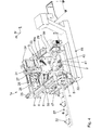
- a machine tool 1 for machining metallic workpieces 2 has a machine bed 3, on which a first side wall 4 and a mirror-symmetrical second side wall 5 are arranged.
- the sidewalls 4, 5 are spaced apart in a horizontal x-direction and are substantially parallel to a yz-plane defined by a vertical y-direction and a horizontal z-direction.
- the x, y, and z directions form a Cartesian coordinate system.
- the side walls 4, 5 each have a substantially rectangular base body 6, on which a Verfahrvorsprung 7, a support projection 8 and a bearing projection 9 are integrally formed.
- the rectangular basic body 6 of the side wall 4 is illustrated by dashed lines.
- Each of the side walls 4, 5 is fixed with its side wall bottom 10 on the machine frame 3.
- the side wall top 11 is free in each case.
- Each side wall top 11 is formed by the associated base top 12, the traversing projection top 13 and the bearing projection top 14, which are aligned with each other.
- the Verfahrvorsprünge 7 are integrally formed on the respective main body front side 15 in the region of the base body top 12.
- the Verfahrvorsprünge 7 extend starting from the respective base body 6 in the z-direction wedge-shaped, so that their Verfahrvorsprung-undersides 16 are inclined relative to the xz-plane.
- the traverse projections 17 are substantially parallel to the xy plane.
- the bearing projections 9 are integrally formed on the main body rear side 18 in the region of the main body upper side 12.
- the bearing projections 9 are formed substantially rectangular.
- Each side wall bottom 10 is formed by the associated base bottom 19 and the support projection bottom 20 which are aligned with each other.
- the support projection 8 of each of the side walls 4, 5 is formed on the main body front side 15 in the region of the base body underside 19. Starting from the respective base body 6, the support projections 8 extend wedge-shaped in the z-direction.
- the support projection upper sides 21 run parallel to the x-z plane, whereas the support projection undersides 20 extend inclined in a partial region facing the support projection front sides 22 relative to the x-z plane.
- the support projection front sides 22 are substantially parallel to the x-y plane.
- z-guide rails 23 are arranged, which extend substantially over the entire main body top 12 and the Verfahrvorsprung top 13 in the z-direction.
- a z-slide 24 is mounted in the manner of a bridge and on the z-guide rails 23 by means of z-drive motors 25 in the z-direction movable.
- the z-drive motors 25 are each mounted on the bearing projection top 14.
- x-guide rails 26 are arranged on the z-slide 24 and in the x-direction x-guide rails 26 are arranged.
- An x-carriage 27 is on mounted the x-guide rails 26 and movable by means of an x-drive motor 28 in the x-direction.
- a tool spindle 29 is arranged vertically suspended.
- the tool spindle 29 is mounted with two mutually parallel and extending in the y-direction y-guide rails 30 on the x-carriage 27 and movable by means of a y-drive motor 31 in the y-direction.
- the tool spindle 29 has a tool holder 33 for receiving a tool 32, which can be driven in rotation by means of a spindle drive motor 34 about a spindle rotational axis 35 extending parallel to the y direction.
- the first free spaces 36 located in the y direction underneath the travel projections 7 and the second free space 37 lying between these free spaces 36 form a processing space 38.
- the processing space 38 serves for the positioning and processing of workpieces 2.
- the support projections 8 and a workpiece positioning unit 39 are arranged for positioning the workpiece 2 to be processed.
- the processing space 38 forming free spaces 36 and 37 are in Fig. 1 illustrated.
- the workpiece positioning unit 39 is designed as a rotary-pivot bridge and has a pivot bridge 40 with a turntable 41 and two bridge drives 42.
- the bridge drives 42 are mounted on the support projection top 21 of the respective support projection 8 and thus arranged in the first free spaces 36.
- the pivoting bridge 40 is connected to the bridge drives 42 and arranged in the second free space 37 about a designated as A-axis and parallel to the x-direction extending first pivot axis 43 pivotally. Center on the Swing bridge 40, the turntable 41 is mounted.
- the turntable 41 is pivotable by means of a turntable drive 44 about a second pivot axis 45 running perpendicular to the pivot bridge 40 and designated as a B axis.
- the bridge drives 42 are arranged on the support projections 8 such that the first pivot axis 43 lies substantially in the plane formed by the movement projection front sides 17.
- the first pivot axis 43 is thus traversable by a corresponding method of the z-slide 24 of the spindle rotation axis 35.
- the bridge drives 42 could be attached to the main body front side 15 or with a corresponding configuration of the Verfahrvorsprünge 7 at its Verfahrvorsprung bottom 16, whereby the support projections 8 would be superfluous.
- the base body 6 of the side walls 4, 5 define between them essentially a working space 46, which is usable for changing tools 32 and / or workpieces 2.
- a working space 46 which is usable for changing tools 32 and / or workpieces 2.
- the base body 6 On first feed openings 47 and second feed openings 48, which are each aligned with each other.
- a tool magazine 49 designed as a chain magazine is arranged in the working space 46 in the region of the base body rear side 18.
- the tool magazine 49 extends beyond the bearing projections 9 and serves to accommodate a plurality of different tools 32.
- the tool magazine 49 is movable by means of a magazine drive 50 in the circumferential direction.
- the tool changer 51 For tool change is a tool changer 51 between the tool magazine 49 and the rotary-pivot bridge 39 arranged.
- the tool changer 51 has a changer arm 52, which can be pivoted by means of a changer drive 53 about a changer axis 54 running parallel to the y-direction.
- the first feed openings 47 are arranged in the area below the tool changer 51, the second feed openings 48 in the region of the tool magazine 49.
- a separate chip collector 55 is disposed below the support projections 8 and the rotary-pivot bridge 39.
- the chip collector 55 has a collecting container 56 with chip conveyors arranged therein and not shown in detail, so that chips produced in the processing of the workpieces 2 can be collected in the collecting container 56 and removed in the x direction.
- both a turning and a milling of the workpiece 2 is possible.
- a turning tool 32 is received in the tool spindle 29 and clamped about the spindle rotation axis 35.
- the turntable 41 is operated at a high speed of, for example, 1200 rpm. By advancing the rotary tool 32, the turning is done.
- the swivel bridge 40 serves to position the workpiece 2.
- the bridge drives 42 have a high positioning accuracy and are operated at speeds of maximum 35 rpm.
- the tool spindle 29 can be moved in the z-direction such that the spindle rotation axis 35, the first pivot axis 43 of the rotary-pivot bridge 39 passes over. This provides high flexibility in workpiece machining.
- the resulting chips during processing fall directly into the chip collector 55 and are removed.
- the guide rails 23, 26 and 30 are arranged outside the processing space 38 and thus protected from contamination, such as from the chips.
- the tool spindle 29 transfers to the changer arm 52 the tool 32 that is no longer required.
- the changer arm 52 removes the tool magazine 49 from the new tool 32, which was previously brought into a corresponding transfer position.
- the new tool 32 of the tool spindle 29 is provided and stored the tool no longer needed in the tool magazine 49.
- the editing of the workpiece 2 are continued.
- the machining of the workpiece 2 is completed, it is manually removed from the turntable 41 and a new workpiece 2 arranged thereon.
- the machine tool 1a additionally has a transport device 57 for supplying and removing workpieces 2 and / or tools 32.
- the transport device 57 is designed as a conveyor belt and traverses the first charging openings 47 and the working space 46.
- the tool magazine 49a is designed as a disk magazine.
- a tool changer is not provided.
- a workpiece gripper or a workpiece change arm 58 is mounted laterally on the tool spindle 29.
- the workpiece gripper 58 may be designed as a single or double gripper. In an embodiment as a double gripper, a workpiece 2 to be machined and a finished workpiece 2 can be grasped simultaneously. As a result, a shortening of the workpiece change times can be achieved. Due to the lateral arrangement on the tool spindle 29, the workpiece gripper 58 can be positioned via the machine's own linear NC axes and thus does not require its own NC axes.
- the workpiece gripper 58 is designed as a piston-cylinder unit and can be extended into a gripping position with a desired stroke in the y-direction. This is in Fig. 4 shown. The arrangement of the workpiece gripper 58 is such that it does not come into collision with the tool spindle 29 and / or a tool 32.
- the workpieces 2 to be processed are first transported by the transport device 57 up to a workpiece change position in the working space 46 and separated there.
- the workpieces 2 can be transported directly on the transport device 57 or on a transport pallet.
- An isolated workpiece 2 is picked up by means of the workpiece gripper 58 located in the gripping position, deposited on the turntable 41 and clamped there in the usual way. Since the workpiece gripper 58 is arranged on the tool spindle 29, it can be moved in the x, y and z directions together with the tool spindle 29.
- the machining of the workpiece 2 is carried out according to the first embodiment.
- the workpiece gripper 58 is in a retracted state during machining, so that it does not collide with the workpiece 2 or the tool 32.
- the finished workpiece 2 is picked up again with the workpiece gripper 58 and deposited on the transport device 57, which removes it.
- the workpiece gripper 58 is designed as a double gripper, then another workpiece 2 to be machined can be picked up by the transport device 57 and placed on the turntable 41.
- Worn tools 32 are also deposited on the transport device 57 and transported away.
- the tool magazine 49a can be equipped with new tools 32 by being transported by means of the transport device 57 into the working space 46 and received there by the tool spindle 29 and deposited directly in the tool magazine 49a.
- FIG. 5 A third embodiment of the invention described.
- Structurally identical parts receive the same reference numerals as in the previous embodiments, the description of which reference is hereby made.
- Structurally different, but functionally similar parts receive the same reference numerals with a trailing b.
- the workpiece gripper 58b is formed in the machine tool 1b as an articulated arm.
- the articulated arm 58b is pivotable about two gripper axes 59 running parallel to the y-direction and linearly movable in the x-direction.
- a workpiece magazine 60 is arranged laterally next to the side wall 4.
- the workpieces 2 are removed from the workpiece magazine 60 by moving and pivoting the articulated arm 58b and arranged on the turntable 41. After machining, the workpiece 2 is removed in a corresponding manner from the turntable 41 and stored again in the workpiece magazine 60.
- the further mode of operation reference is made to the preceding embodiments.
- the tool magazine 49c of the machine tool 1c is designed as a shelf magazine and arranged laterally next to the side wall 5.
- the tool magazine 49c has a tool transport device with a gripping arm 61.
- the gripping arm 61 is pivotable about a parallel to the y-direction gripping arm 62 and in the Y-direction movable hinged to a Greifarmanii 63.
- a tool rest 64 is arranged on the machine bed 3 in the region of the second loading opening 48 of the side wall 5.
- the tool tray 64 can be used as a single tool holder - as in Fig. 6 shown - or be designed as empty space in a tool magazine.
- the gripper arm 61 removes a new tool 32 from the tool magazine 49c and transports it by turning and moving the gripper arm 61 through the second feed opening 48 to the tool tray 64, where the tool 32 is deposited.
- the tool spindle 29 is moved to the tool rest 64, where it receives the stored tool 32. Subsequently, the workpiece 32 is carried out with the tool 32. A no longer needed tool 32 is stored in a corresponding manner again in the tool magazine 49c.
- the storage capacity of the tool magazine 49c can in principle be increased indefinitely.
- the gripping of the workpieces 2 takes place with the workpiece gripper 58, which is arranged laterally on the tool spindle 29 in accordance with the second exemplary embodiment.
- the workpiece gripper 58 which is arranged laterally on the tool spindle 29 in accordance with the second exemplary embodiment.
- the workpiece positioning unit 39d of the machine tool 1d is designed for machining wave-shaped and / or flange-shaped workpieces 2.
- a first formed as a workpiece spindle workpiece holder 65 is parallel to the attached to the xz plane extending Verfahrvorsprung bottom 16 d of the side wall 4 d.
- a second workpiece holder 66 designed as a workpiece spindle is fastened on a second x-slide 67.
- the x-slide 67 is mounted on second x-guide rails 68 and movable by means of a second x-drive motor 69 in the x-direction.
- the second x-guide rails 68 are attached to a machine bed front side 70 and to the main body front sides 15 d, so that they extend over the entire processing space 38.
- the workpiece spindles 65, 66 each have an associated workpiece spindle drive motor 71, so that a workpiece 2 accommodated in the workpiece spindles 65, 66 can be driven in rotation about the pivot axis 43.
- a tool turret 72 with a turret disk 73 and a turret drive motor 74 is provided.
- the turret disk 73 can be pivoted by means of the turret drive motor 74 about a turret axis 75 running parallel to the x-direction.
- the tool turret 72 is disposed on a y-carriage 76 which is movable on second y-guide rails 77 by means of a second y-drive motor 78 in the y-direction.
- the second y-guide rails 77 are arranged on a third x-slide 79, which is movable on the second x-guide rails 68 by means of a third x-drive motor 80 in the x-direction.
- the tool turret 72 is arranged on the side of the second x-slide 67 facing the first workpiece spindle 65.
- the supply and removal of the workpieces 2 takes place manually. Wavy workpieces 2 are received in both workpiece spindles 65, 66 and rotationally driven.
- the machining takes place by means of the tool spindle 29 and / or the tool turret 72.
- the tool turret 72 can be moved in the processing space 38 underneath the workpiece 2 and the first workpiece spindle 65 in any direction in the x and y directions.
- the tool turret 72 is extremely rigid due to its short lever arms.
- the turning of the wave-shaped workpieces 2 is preferably performed with the tool turret 72, as this roundnesses and coaxialities of the individual wave-shaped sections with tolerances in the micrometer range can be achieved.
- the tool spindle 29 is preferably used, which can be positioned over the three linear NC axes in the x-, y- and z-direction. Without a new clamping of the workpiece 2 29 different drilling, threading and milling are possible by means of the tool spindle.
- the interpolation capability of the three linear NC axes in conjunction with the pivot axis 43 can also be used to produce complicated prismatic and / or spherical geometries of the workpiece 2.
- flange-shaped workpieces 2 can be processed on both sides.
- the workpiece 2 is first received in the first workpiece spindle 65 and processed by means of the tool spindle 29 and / or the tool turret 72.
- the second workpiece spindle 66 is moved to the first workpiece spindle 65 and the workpiece 2 is transferred to the second workpiece spindle 66.
- the workpiece 2 can now be processed by means of the tool spindle 29 and / or the tool turret 72 on the previously clamped side.
- a new workpiece 2 can be clamped and processed in the first workpiece spindle 65. If workpieces 2 are received in both workpiece spindles 65, 66, then the tool spindle 29 can machine one workpiece turret 72 and the other workpiece 2.
- the machine tool 1e has a workpiece magazine 60e which can feed the wavy workpieces 2 through the first workpiece spindle 65e and the second workpiece spindle 66 and discharge them in a corresponding manner.
- the workpiece magazine 60e thus enables automatic feeding and removal of workpieces 2.
- the first workpiece spindle 65e is fastened to the main body front side 15e in contrast to the preceding exemplary embodiment. With regard to the further mode of operation, reference is made to the preceding embodiments.
- the workpiece positioning unit 39f of the machine tool 1f is formed as a two-axis table.
- the machine bed 3f has a pivoting part 81 arranged such that the first pivot axis 43f in the yz plane is inclined by 45 ° relative to the y-direction and extends into the processing space 38.
- the swivel part 81 is pivoted about the first pivot axis 43f by means of a swivel drive 82 integrated in the machine bed 3f.
- the turntable 41f is arranged on the swivel part 81 in such a way that the second swivel axis 45f forms an angle of 135 ° with the first swivel axis 43f. In the in Fig. 10 shown position, the second pivot axis 45f is thus parallel to the y-direction.
- the turntable 41f is arranged substantially in the processing space 38 below the movement projections 7f.
- the turntable drive 44 is integrated into the pivoting part 81.
- the machine tool 1g is double-spindleed and has two juxtaposed tool spindles 29g, which can be moved together in the y-direction.
- the Werk Swisspositionierillon 39g is formed according to the first to third embodiment as a rotary-pivot bridge and has two juxtaposed turntable 41. With the machine tool 1g a simultaneous machining of two workpieces 2 is possible. With regard to the further mode of operation, reference is made to the preceding embodiments.
- the machine tool 1h is double-spindleed and has two juxtaposed tool spindles 29h, which are movable together in the y-direction.
- the machine tool 1h has two Maschinen Anlagenpositioniertechniken 39h, each having a positioning drive 83 and a cross-sectional polygonal workpiece carrier 84.
- the positioning drives 83 are mounted on the support projections 8h.
- the workpiece carriers 84 are each connected to one of the positioning drives 83 and independent from each other about the common pivot axis 43 pivotally.
- the workpiece carriers 84 each extend in the direction of the processing space 38 and face each other.
- Each workpiece carrier 84 has a plurality of polygon sides 85 on its outer circumference. At each polygon side 85, two workpiece holders 86 are arranged next to one another in the x-direction. The number and the distance of the workpiece holders 86 correspond to the number and the distance of the tool spindles 29h, so that two workpieces 2 can be processed simultaneously.
- the workpiece holders 86 are formed, for example, as a clamping device.
- the workpiece carriers 84 each have a cylindrical bore 87.
- the workpiece carriers 84 are thus formed as a hollow cylinder with a polygonal in cross section outer circumference. Between the workpiece positioning units 39h, a vertical partition 88 is disposed and fixed to the machine bed 3h. On each side of the partition 88, a louver-like cover 89 is guided for the workpiece carrier 84.
- the machine tools 1, 1a to 1h are modular.
- the individual modules machine bed 3, 3f, 3h, side walls 4, 4d, 4e, 4f, 4h, 5, 5d, 5e, 5f, 5h, carriage 24, 27, tool spindle 29, 29g, 29h, workpiece positioning units 39, 39d, 39e, 39f, 39g, 39h, tool magazine 49, 49a to 49h, chip collector 55, conveyor 57 and workpiece gripper 58, 58b can be combined with each other as required.
- the machine tools 1a to 1h can be easily configured for different machining processes, such as turning, milling, grinding, tapping or gear cutting.
- the method of the carriages 24, 27 and the tool spindle 29, 29g, 29h can be done via ball screws and / or linear drives.
- a freely accessible processing space 38 is generated, which is adaptable by varying the length of the Verfahrvorsprünge 7, 7d to 7f, 7h within wide limits.
- a wide variety of workpiece positioning units 39, 39d, 39e, 39f, 39g, 39h can be arranged in the processing space 38, as a result of which the machine tools 1, 1a to 1h can be designed for a very wide variety of machining tasks.
Landscapes
- Engineering & Computer Science (AREA)
- Mechanical Engineering (AREA)
- Machine Tool Units (AREA)
- Turning (AREA)
- Automatic Tool Replacement In Machine Tools (AREA)
Applications Claiming Priority (2)
| Application Number | Priority Date | Filing Date | Title |
|---|---|---|---|
| DE102009025009A DE102009025009A1 (de) | 2009-06-16 | 2009-06-16 | Werkzeugmaschine zur Bearbeitung von Werkstücken |
| DE102009054043A DE102009054043A1 (de) | 2009-11-20 | 2009-11-20 | Werkzeugmaschine zur Bearbeitung von Werkstücken |
Publications (2)
| Publication Number | Publication Date |
|---|---|
| EP2263827A1 true EP2263827A1 (fr) | 2010-12-22 |
| EP2263827B1 EP2263827B1 (fr) | 2012-01-04 |
Family
ID=42674591
Family Applications (1)
| Application Number | Title | Priority Date | Filing Date |
|---|---|---|---|
| EP10164497A Revoked EP2263827B1 (fr) | 2009-06-16 | 2010-05-31 | Appareil pour usiner des pièces |
Country Status (4)
| Country | Link |
|---|---|
| US (1) | US8529420B2 (fr) |
| EP (1) | EP2263827B1 (fr) |
| CN (1) | CN101920472B (fr) |
| AT (1) | ATE539843T1 (fr) |
Cited By (6)
| Publication number | Priority date | Publication date | Assignee | Title |
|---|---|---|---|---|
| WO2012089563A1 (fr) * | 2010-12-28 | 2012-07-05 | Deckel Maho Pfronten Gmbh | Machine-outil commandée par programme |
| DE102011080457A1 (de) | 2011-08-04 | 2013-02-07 | Mag Ias Gmbh | Werkzeugmaschine zur Bearbeitung von Werkstücken |
| EP2345503A3 (fr) * | 2010-01-19 | 2013-06-05 | Deckel Maho Seebach GmbH | Machine-outil |
| EP2745968A3 (fr) * | 2012-12-19 | 2015-02-11 | Fu Ding Electronical Technology (Jiashan) Co., Ltd. | Procédé de fraisage pour l'usinage d'un élément métallique |
| CN105261285A (zh) * | 2015-10-21 | 2016-01-20 | 天津明大通元科技发展有限公司 | 一种模块化多功能数控机床及其应用 |
| EP4015143A4 (fr) * | 2019-08-16 | 2024-01-10 | Kede Numerical Control Co Ltd | Système de traitement vertical à cinq axes pour chargement et déchargement automatiques |
Families Citing this family (40)
| Publication number | Priority date | Publication date | Assignee | Title |
|---|---|---|---|---|
| TW201304898A (zh) * | 2011-07-25 | 2013-02-01 | Chuan-Zhou Cao | 多軸工具機 |
| DE102012002982B4 (de) * | 2012-02-15 | 2016-01-14 | Emag Holding Gmbh | Werkzeugmaschine mit A-Achse |
| JP5897210B2 (ja) * | 2012-05-29 | 2016-03-30 | 北京巴付勒▲伝▼▲動▼技▲術▼有限公司 | モジュールの大きい歯車用の多目的歯切り盤 |
| CN103567799B (zh) * | 2012-07-20 | 2016-08-03 | 鸿准精密模具(昆山)有限公司 | 进给装置及应用该进给装置的机床 |
| CN103567465B (zh) * | 2012-07-20 | 2019-10-29 | 鸿准精密模具(昆山)有限公司 | 车削设备 |
| CN103567800A (zh) * | 2012-07-20 | 2014-02-12 | 鸿准精密模具(昆山)有限公司 | 进给装置及应用该进给装置的机床 |
| CN103567462A (zh) * | 2012-07-20 | 2014-02-12 | 鸿准精密模具(昆山)有限公司 | 车床 |
| CN103878589B (zh) * | 2012-12-19 | 2016-12-28 | 鸿准精密模具(昆山)有限公司 | 金属件加工方法 |
| CN103878534B (zh) * | 2012-12-19 | 2016-05-11 | 鸿准精密模具(昆山)有限公司 | 金属件加工方法 |
| CN103878592B (zh) | 2012-12-19 | 2017-06-06 | 鸿准精密模具(昆山)有限公司 | 机床 |
| CN103878591B (zh) | 2012-12-19 | 2016-12-28 | 鸿准精密模具(昆山)有限公司 | 金属件加工方法 |
| CN103878590A (zh) * | 2012-12-19 | 2014-06-25 | 鸿准精密模具(昆山)有限公司 | 机床 |
| CN103878636B (zh) * | 2012-12-19 | 2018-05-04 | 鸿准精密模具(昆山)有限公司 | 机床控制系统 |
| CN103878635B (zh) * | 2012-12-19 | 2018-05-04 | 鸿准精密模具(昆山)有限公司 | 机床控制系统 |
| CN103878622B (zh) | 2012-12-19 | 2016-08-03 | 鸿准精密模具(昆山)有限公司 | 刀库及使用该刀库的机床 |
| JP5474266B1 (ja) * | 2012-12-20 | 2014-04-16 | ヤマザキマザック株式会社 | 工作機械の内径旋削アタッチメント |
| TW201427793A (zh) * | 2013-01-07 | 2014-07-16 | Hsiu Fong Machinery Co Ltd | 雙加工頭圓盤式同步換刀系統 |
| CN104416406B (zh) * | 2013-09-11 | 2017-03-01 | 富鼎电子科技(嘉善)有限公司 | 进给装置及采用该进给装置的双轴加工机 |
| ES2791712T3 (es) * | 2013-09-27 | 2020-11-05 | Siemens Ag | Equipo de control con optimizador integrado |
| RU2016137477A (ru) * | 2014-02-21 | 2018-03-26 | Ск-Текнолоджиз Уг | Роботизированный модуль для параллельной основному машинному времени загрузки и разгрузки однопозиционных металлорежущих станков |
| DE102014102938A1 (de) * | 2014-03-05 | 2015-09-10 | Haas Schleifmaschinen Gmbh | Bearbeitungsmaschine, insbesondere Schleifmaschine |
| WO2016027328A1 (fr) * | 2014-08-20 | 2016-02-25 | 富士機械製造株式会社 | Centre d'usinage |
| WO2016027327A1 (fr) * | 2014-08-20 | 2016-02-25 | 富士機械製造株式会社 | Centre d'usinage |
| TW201607672A (zh) * | 2014-08-25 | 2016-03-01 | 東台精機股份有限公司 | 加工機 |
| BG2292U1 (bg) * | 2014-10-20 | 2016-10-31 | "Ред Стиил" ЕООД | Машина за обработване на метални обемни обекти |
| CN104476206A (zh) * | 2014-12-03 | 2015-04-01 | 佛山市普拉迪数控科技有限公司 | 一种可移动的悬挂加工设备 |
| CN104526447B (zh) * | 2014-12-31 | 2017-12-19 | 苏州达力客自动化科技有限公司 | 全自动机加工转移系统 |
| CN104827354A (zh) * | 2015-04-28 | 2015-08-12 | 佛山市普拉迪数控科技有限公司 | 一种多轴加工的数控机床 |
| DE102015218206A1 (de) * | 2015-09-22 | 2017-03-23 | Deckel Maho Pfronten Gmbh | Werkzeugmaschine, insbesondere mehrfachspindel-fräsmaschine |
| US10556307B2 (en) | 2015-09-30 | 2020-02-11 | Makino Milling Machine Co., Ltd. | Machine tool |
| CN105881106B (zh) * | 2016-05-27 | 2019-08-16 | 宿迁市通用机械有限公司 | 一种高压互感器法兰加工用机床 |
| JP6729256B2 (ja) * | 2016-09-30 | 2020-07-22 | ブラザー工業株式会社 | 工作機械 |
| CN106695353B (zh) * | 2017-01-20 | 2023-07-14 | 仲恺农业工程学院 | 一种可自动定位加工的智能数控机床 |
| DE102017116718A1 (de) * | 2017-07-24 | 2019-01-24 | Broetje-Automation Gmbh | Bearbeitungsanlage für Flugzeugstrukturbauteile |
| DE102017216446A1 (de) * | 2017-09-17 | 2019-03-21 | Deckel Maho Seebach Gmbh | Werkzeugmaschine zur Bearbeitung eines Werkstücks |
| DE102018130925A1 (de) * | 2018-12-05 | 2020-06-10 | Stama Maschinenfabrik Gmbh | Werkzeugmaschine mit Werkzeugspindel und Ladeportal |
| CN109940208A (zh) * | 2019-04-26 | 2019-06-28 | 浙江百信针织机械有限公司 | 一种数控龙门针槽铣床 |
| CN110449956A (zh) * | 2019-07-19 | 2019-11-15 | 科德数控股份有限公司 | 一种多主轴的全自动立式加工中心 |
| EP3769912A1 (fr) * | 2019-07-23 | 2021-01-27 | Erst-Maschinenbau GmbH | Cocon machine-outil, dispositif changeur d'outil et machine-outil |
| CN110605607B (zh) * | 2019-09-27 | 2024-04-16 | 科德数控股份有限公司 | 自动上下料加工系统 |
Citations (3)
| Publication number | Priority date | Publication date | Assignee | Title |
|---|---|---|---|---|
| WO2002000390A1 (fr) * | 2000-06-28 | 2002-01-03 | Modig Machine Tool Ab | Machine a usages multiples munie d'un bati en u comportant plusieurs ouvertures |
| EP0568798B9 (fr) | 1992-04-10 | 2004-05-06 | Emag Maschinenfabrik Gmbh | Centre d'usinage formée par un assemblage de modules |
| US20060270540A1 (en) * | 2005-05-25 | 2006-11-30 | Mori Seiki Co., Ltd. | Machine Tool |
Family Cites Families (8)
| Publication number | Priority date | Publication date | Assignee | Title |
|---|---|---|---|---|
| JPS6017929U (ja) * | 1983-07-15 | 1985-02-06 | 株式会社 不二精機製造所 | マシンニングセンタの機体 |
| GB9204769D0 (en) * | 1992-03-05 | 1992-04-15 | Black & Decker Inc | Workcentre and supports |
| JPH11340695A (ja) * | 1998-05-25 | 1999-12-10 | Sony Corp | 組立装置 |
| DE19948822A1 (de) | 1999-10-09 | 2001-04-19 | Heller Geb Gmbh Maschf | Vorrichtung zur Bearbeitung von Werkstücken sowie Verfahren zur Bearbeitung von Werkstücken unter Verwendung einer solchen Vorrichtung |
| DE10029967B4 (de) * | 2000-06-26 | 2006-08-03 | Satisloh Gmbh | Vorrichtung zur Bearbeitung von optischen Werkstücken |
| JP2003326431A (ja) * | 2002-05-09 | 2003-11-18 | Takeda Kikai:Kk | 工作機械 |
| DE20211744U1 (de) | 2002-07-30 | 2002-09-19 | Ilg Gmbh | Werkzeugmaschine zum Bearbeiten von Futterteilen |
| JP2004160584A (ja) * | 2002-11-12 | 2004-06-10 | Mori Seiki Co Ltd | 多軸加工工作機械及びテーブルユニット着脱用治具 |
-
2010
- 2010-05-31 AT AT10164497T patent/ATE539843T1/de active
- 2010-05-31 EP EP10164497A patent/EP2263827B1/fr not_active Revoked
- 2010-06-15 US US12/815,819 patent/US8529420B2/en not_active Expired - Fee Related
- 2010-06-17 CN CN2010102063971A patent/CN101920472B/zh not_active Expired - Fee Related
Patent Citations (3)
| Publication number | Priority date | Publication date | Assignee | Title |
|---|---|---|---|---|
| EP0568798B9 (fr) | 1992-04-10 | 2004-05-06 | Emag Maschinenfabrik Gmbh | Centre d'usinage formée par un assemblage de modules |
| WO2002000390A1 (fr) * | 2000-06-28 | 2002-01-03 | Modig Machine Tool Ab | Machine a usages multiples munie d'un bati en u comportant plusieurs ouvertures |
| US20060270540A1 (en) * | 2005-05-25 | 2006-11-30 | Mori Seiki Co., Ltd. | Machine Tool |
Cited By (7)
| Publication number | Priority date | Publication date | Assignee | Title |
|---|---|---|---|---|
| EP2345503A3 (fr) * | 2010-01-19 | 2013-06-05 | Deckel Maho Seebach GmbH | Machine-outil |
| WO2012089563A1 (fr) * | 2010-12-28 | 2012-07-05 | Deckel Maho Pfronten Gmbh | Machine-outil commandée par programme |
| DE102011080457A1 (de) | 2011-08-04 | 2013-02-07 | Mag Ias Gmbh | Werkzeugmaschine zur Bearbeitung von Werkstücken |
| EP2745968A3 (fr) * | 2012-12-19 | 2015-02-11 | Fu Ding Electronical Technology (Jiashan) Co., Ltd. | Procédé de fraisage pour l'usinage d'un élément métallique |
| US9381580B2 (en) | 2012-12-19 | 2016-07-05 | Fu Ding Electronical Technology (Jiashan) Co., Ltd. | Milling method for machining metallic member |
| CN105261285A (zh) * | 2015-10-21 | 2016-01-20 | 天津明大通元科技发展有限公司 | 一种模块化多功能数控机床及其应用 |
| EP4015143A4 (fr) * | 2019-08-16 | 2024-01-10 | Kede Numerical Control Co Ltd | Système de traitement vertical à cinq axes pour chargement et déchargement automatiques |
Also Published As
| Publication number | Publication date |
|---|---|
| EP2263827B1 (fr) | 2012-01-04 |
| ATE539843T1 (de) | 2012-01-15 |
| US20100313718A1 (en) | 2010-12-16 |
| US8529420B2 (en) | 2013-09-10 |
| CN101920472B (zh) | 2012-11-07 |
| CN101920472A (zh) | 2010-12-22 |
Similar Documents
| Publication | Publication Date | Title |
|---|---|---|
| EP2263827B1 (fr) | Appareil pour usiner des pièces | |
| EP1733840B1 (fr) | Système de machine-outil avec un robot et un magazin pour outils | |
| DE102005017523B4 (de) | Verfahren zum Bearbeiten von Werkstücken mittels einer Werkzeugmaschine | |
| EP1765550B1 (fr) | Machine-outil | |
| DE3721610C2 (fr) | ||
| DE102009025009A1 (de) | Werkzeugmaschine zur Bearbeitung von Werkstücken | |
| EP1718435B1 (fr) | Machine d'usinage pour usiner des pieces | |
| DE2739534C2 (de) | Werkzeugwechselvorrichtung | |
| DE102006050425B4 (de) | Vorrichtung zum Fräsen und Drehen sowie Verfahren zum Bearbeiten eines Linsenrohlings | |
| DE3416660A1 (de) | Drehmaschine | |
| WO2002000388A1 (fr) | Dispositif d'usinage de pieces au moyen d'au moins une machine-outil | |
| EP0558720A1 (fr) | Centre d'usinage servant a usiner une piece a l'aide d'au moins deux outils interchangeables | |
| EP2753454B1 (fr) | Machine-outil | |
| DE102009054043A1 (de) | Werkzeugmaschine zur Bearbeitung von Werkstücken | |
| EP1413395A1 (fr) | Machine-outil | |
| DE10119175A1 (de) | Vorrichtung zur Bearbeitung von Werkstücken sowie Verfahren zur Bearbeitung von Werkstücken unter Verwendung einer solchen Vorrichtung | |
| EP0885686A1 (fr) | Centre d'usinage | |
| DE10034973C2 (de) | Universalwerkzeugmaschine mit im Pick-up Modus wechselbaren Werkstückträger | |
| EP0612278B1 (fr) | Tour automatique multibroche | |
| EP1294530B1 (fr) | Machine-outil destinee a l'usinage au moins triaxial de pieces | |
| EP1511596B1 (fr) | Tour multibroche | |
| DE102011081717B4 (de) | Werkzeugmaschine zur Bearbeitung von Werkstücken | |
| DE19803563C1 (de) | Werkzeugmaschine, insbesondere Drehmaschine mit wenigstens einer hängend angeordneten horizontalen Arbeitsspindel | |
| EP2762253B1 (fr) | Machine-outil destinée au traitement de pièces à usiner | |
| DE10235518B4 (de) | Verfahren und Vorrichtung zur Werkstück-Bearbeitung |
Legal Events
| Date | Code | Title | Description |
|---|---|---|---|
| PUAI | Public reference made under article 153(3) epc to a published international application that has entered the european phase |
Free format text: ORIGINAL CODE: 0009012 |
|
| AK | Designated contracting states |
Kind code of ref document: A1 Designated state(s): AL AT BE BG CH CY CZ DE DK EE ES FI FR GB GR HR HU IE IS IT LI LT LU LV MC MK MT NL NO PL PT RO SE SI SK SM TR |
|
| AX | Request for extension of the european patent |
Extension state: BA ME RS |
|
| 17P | Request for examination filed |
Effective date: 20110311 |
|
| RIC1 | Information provided on ipc code assigned before grant |
Ipc: B23Q 1/01 20060101AFI20110617BHEP |
|
| GRAP | Despatch of communication of intention to grant a patent |
Free format text: ORIGINAL CODE: EPIDOSNIGR1 |
|
| GRAS | Grant fee paid |
Free format text: ORIGINAL CODE: EPIDOSNIGR3 |
|
| GRAA | (expected) grant |
Free format text: ORIGINAL CODE: 0009210 |
|
| AK | Designated contracting states |
Kind code of ref document: B1 Designated state(s): AL AT BE BG CH CY CZ DE DK EE ES FI FR GB GR HR HU IE IS IT LI LT LU LV MC MK MT NL NO PL PT RO SE SI SK SM TR |
|
| REG | Reference to a national code |
Ref country code: GB Ref legal event code: FG4D Free format text: NOT ENGLISH |
|
| REG | Reference to a national code |
Ref country code: CH Ref legal event code: EP |
|
| REG | Reference to a national code |
Ref country code: AT Ref legal event code: REF Ref document number: 539843 Country of ref document: AT Kind code of ref document: T Effective date: 20120115 |
|
| REG | Reference to a national code |
Ref country code: IE Ref legal event code: FG4D |
|
| REG | Reference to a national code |
Ref country code: DE Ref legal event code: R096 Ref document number: 502010000331 Country of ref document: DE Effective date: 20120308 |
|
| PLBI | Opposition filed |
Free format text: ORIGINAL CODE: 0009260 |
|
| REG | Reference to a national code |
Ref country code: SE Ref legal event code: TRGR |
|
| 26 | Opposition filed |
Opponent name: MASCHINENFABRIK BERTHOLD HERMLE AG Effective date: 20120229 |
|
| REG | Reference to a national code |
Ref country code: NL Ref legal event code: VDEP Effective date: 20120104 |
|
| PG25 | Lapsed in a contracting state [announced via postgrant information from national office to epo] |
Ref country code: SI Free format text: LAPSE BECAUSE OF FAILURE TO SUBMIT A TRANSLATION OF THE DESCRIPTION OR TO PAY THE FEE WITHIN THE PRESCRIBED TIME-LIMIT Effective date: 20120104 |
|
| REG | Reference to a national code |
Ref country code: DE Ref legal event code: R026 Ref document number: 502010000331 Country of ref document: DE Effective date: 20120229 |
|
| LTIE | Lt: invalidation of european patent or patent extension |
Effective date: 20120104 |
|
| PG25 | Lapsed in a contracting state [announced via postgrant information from national office to epo] |
Ref country code: IS Free format text: LAPSE BECAUSE OF FAILURE TO SUBMIT A TRANSLATION OF THE DESCRIPTION OR TO PAY THE FEE WITHIN THE PRESCRIBED TIME-LIMIT Effective date: 20120504 Ref country code: NO Free format text: LAPSE BECAUSE OF FAILURE TO SUBMIT A TRANSLATION OF THE DESCRIPTION OR TO PAY THE FEE WITHIN THE PRESCRIBED TIME-LIMIT Effective date: 20120404 Ref country code: LT Free format text: LAPSE BECAUSE OF FAILURE TO SUBMIT A TRANSLATION OF THE DESCRIPTION OR TO PAY THE FEE WITHIN THE PRESCRIBED TIME-LIMIT Effective date: 20120104 Ref country code: HR Free format text: LAPSE BECAUSE OF FAILURE TO SUBMIT A TRANSLATION OF THE DESCRIPTION OR TO PAY THE FEE WITHIN THE PRESCRIBED TIME-LIMIT Effective date: 20120104 Ref country code: BG Free format text: LAPSE BECAUSE OF FAILURE TO SUBMIT A TRANSLATION OF THE DESCRIPTION OR TO PAY THE FEE WITHIN THE PRESCRIBED TIME-LIMIT Effective date: 20120404 Ref country code: NL Free format text: LAPSE BECAUSE OF FAILURE TO SUBMIT A TRANSLATION OF THE DESCRIPTION OR TO PAY THE FEE WITHIN THE PRESCRIBED TIME-LIMIT Effective date: 20120104 |
|
| REG | Reference to a national code |
Ref country code: IE Ref legal event code: FD4D |
|
| PG25 | Lapsed in a contracting state [announced via postgrant information from national office to epo] |
Ref country code: LV Free format text: LAPSE BECAUSE OF FAILURE TO SUBMIT A TRANSLATION OF THE DESCRIPTION OR TO PAY THE FEE WITHIN THE PRESCRIBED TIME-LIMIT Effective date: 20120104 Ref country code: FI Free format text: LAPSE BECAUSE OF FAILURE TO SUBMIT A TRANSLATION OF THE DESCRIPTION OR TO PAY THE FEE WITHIN THE PRESCRIBED TIME-LIMIT Effective date: 20120104 Ref country code: PL Free format text: LAPSE BECAUSE OF FAILURE TO SUBMIT A TRANSLATION OF THE DESCRIPTION OR TO PAY THE FEE WITHIN THE PRESCRIBED TIME-LIMIT Effective date: 20120104 Ref country code: GR Free format text: LAPSE BECAUSE OF FAILURE TO SUBMIT A TRANSLATION OF THE DESCRIPTION OR TO PAY THE FEE WITHIN THE PRESCRIBED TIME-LIMIT Effective date: 20120405 Ref country code: PT Free format text: LAPSE BECAUSE OF FAILURE TO SUBMIT A TRANSLATION OF THE DESCRIPTION OR TO PAY THE FEE WITHIN THE PRESCRIBED TIME-LIMIT Effective date: 20120504 |
|
| PG25 | Lapsed in a contracting state [announced via postgrant information from national office to epo] |
Ref country code: CY Free format text: LAPSE BECAUSE OF FAILURE TO SUBMIT A TRANSLATION OF THE DESCRIPTION OR TO PAY THE FEE WITHIN THE PRESCRIBED TIME-LIMIT Effective date: 20120104 |
|
| PG25 | Lapsed in a contracting state [announced via postgrant information from national office to epo] |
Ref country code: DK Free format text: LAPSE BECAUSE OF FAILURE TO SUBMIT A TRANSLATION OF THE DESCRIPTION OR TO PAY THE FEE WITHIN THE PRESCRIBED TIME-LIMIT Effective date: 20120104 Ref country code: CZ Free format text: LAPSE BECAUSE OF FAILURE TO SUBMIT A TRANSLATION OF THE DESCRIPTION OR TO PAY THE FEE WITHIN THE PRESCRIBED TIME-LIMIT Effective date: 20120104 Ref country code: RO Free format text: LAPSE BECAUSE OF FAILURE TO SUBMIT A TRANSLATION OF THE DESCRIPTION OR TO PAY THE FEE WITHIN THE PRESCRIBED TIME-LIMIT Effective date: 20120104 Ref country code: IE Free format text: LAPSE BECAUSE OF FAILURE TO SUBMIT A TRANSLATION OF THE DESCRIPTION OR TO PAY THE FEE WITHIN THE PRESCRIBED TIME-LIMIT Effective date: 20120104 Ref country code: EE Free format text: LAPSE BECAUSE OF FAILURE TO SUBMIT A TRANSLATION OF THE DESCRIPTION OR TO PAY THE FEE WITHIN THE PRESCRIBED TIME-LIMIT Effective date: 20120104 |
|
| PLAX | Notice of opposition and request to file observation + time limit sent |
Free format text: ORIGINAL CODE: EPIDOSNOBS2 |
|
| BERE | Be: lapsed |
Owner name: MAG IAS G.M.B.H. Effective date: 20120531 |
|
| PG25 | Lapsed in a contracting state [announced via postgrant information from national office to epo] |
Ref country code: SK Free format text: LAPSE BECAUSE OF FAILURE TO SUBMIT A TRANSLATION OF THE DESCRIPTION OR TO PAY THE FEE WITHIN THE PRESCRIBED TIME-LIMIT Effective date: 20120104 |
|
| PG25 | Lapsed in a contracting state [announced via postgrant information from national office to epo] |
Ref country code: MC Free format text: LAPSE BECAUSE OF NON-PAYMENT OF DUE FEES Effective date: 20120531 |
|
| PG25 | Lapsed in a contracting state [announced via postgrant information from national office to epo] |
Ref country code: BE Free format text: LAPSE BECAUSE OF NON-PAYMENT OF DUE FEES Effective date: 20120531 Ref country code: MK Free format text: LAPSE BECAUSE OF FAILURE TO SUBMIT A TRANSLATION OF THE DESCRIPTION OR TO PAY THE FEE WITHIN THE PRESCRIBED TIME-LIMIT Effective date: 20120104 |
|
| PLAF | Information modified related to communication of a notice of opposition and request to file observations + time limit |
Free format text: ORIGINAL CODE: EPIDOSCOBS2 |
|
| PLBB | Reply of patent proprietor to notice(s) of opposition received |
Free format text: ORIGINAL CODE: EPIDOSNOBS3 |
|
| PG25 | Lapsed in a contracting state [announced via postgrant information from national office to epo] |
Ref country code: ES Free format text: LAPSE BECAUSE OF FAILURE TO SUBMIT A TRANSLATION OF THE DESCRIPTION OR TO PAY THE FEE WITHIN THE PRESCRIBED TIME-LIMIT Effective date: 20120415 |
|
| PG25 | Lapsed in a contracting state [announced via postgrant information from national office to epo] |
Ref country code: MT Free format text: LAPSE BECAUSE OF FAILURE TO SUBMIT A TRANSLATION OF THE DESCRIPTION OR TO PAY THE FEE WITHIN THE PRESCRIBED TIME-LIMIT Effective date: 20120104 |
|
| PGFP | Annual fee paid to national office [announced via postgrant information from national office to epo] |
Ref country code: SE Payment date: 20130521 Year of fee payment: 4 Ref country code: DE Payment date: 20130522 Year of fee payment: 4 |
|
| PG25 | Lapsed in a contracting state [announced via postgrant information from national office to epo] |
Ref country code: AL Free format text: LAPSE BECAUSE OF FAILURE TO SUBMIT A TRANSLATION OF THE DESCRIPTION OR TO PAY THE FEE WITHIN THE PRESCRIBED TIME-LIMIT Effective date: 20120104 |
|
| PG25 | Lapsed in a contracting state [announced via postgrant information from national office to epo] |
Ref country code: TR Free format text: LAPSE BECAUSE OF FAILURE TO SUBMIT A TRANSLATION OF THE DESCRIPTION OR TO PAY THE FEE WITHIN THE PRESCRIBED TIME-LIMIT Effective date: 20120104 |
|
| PLAB | Opposition data, opponent's data or that of the opponent's representative modified |
Free format text: ORIGINAL CODE: 0009299OPPO |
|
| PG25 | Lapsed in a contracting state [announced via postgrant information from national office to epo] |
Ref country code: LU Free format text: LAPSE BECAUSE OF NON-PAYMENT OF DUE FEES Effective date: 20120531 Ref country code: SM Free format text: LAPSE BECAUSE OF FAILURE TO SUBMIT A TRANSLATION OF THE DESCRIPTION OR TO PAY THE FEE WITHIN THE PRESCRIBED TIME-LIMIT Effective date: 20120104 |
|
| R26 | Opposition filed (corrected) |
Opponent name: MASCHINENFABRIK BERTHOLD HERMLE AG Effective date: 20120229 |
|
| RDAF | Communication despatched that patent is revoked |
Free format text: ORIGINAL CODE: EPIDOSNREV1 |
|
| REG | Reference to a national code |
Ref country code: DE Ref legal event code: R103 Ref document number: 502010000331 Country of ref document: DE Ref country code: DE Ref legal event code: R064 Ref document number: 502010000331 Country of ref document: DE |
|
| PG25 | Lapsed in a contracting state [announced via postgrant information from national office to epo] |
Ref country code: HU Free format text: LAPSE BECAUSE OF FAILURE TO SUBMIT A TRANSLATION OF THE DESCRIPTION OR TO PAY THE FEE WITHIN THE PRESCRIBED TIME-LIMIT Effective date: 20100531 |
|
| PGFP | Annual fee paid to national office [announced via postgrant information from national office to epo] |
Ref country code: IT Payment date: 20140520 Year of fee payment: 5 Ref country code: FR Payment date: 20140516 Year of fee payment: 5 |
|
| RDAG | Patent revoked |
Free format text: ORIGINAL CODE: 0009271 |
|
| STAA | Information on the status of an ep patent application or granted ep patent |
Free format text: STATUS: PATENT REVOKED |
|
| REG | Reference to a national code |
Ref country code: CH Ref legal event code: PLX |
|
| 27W | Patent revoked |
Effective date: 20140623 |
|
| GBPR | Gb: patent revoked under art. 102 of the ep convention designating the uk as contracting state |
Effective date: 20140623 |
|
| REG | Reference to a national code |
Ref country code: DE Ref legal event code: R107 Ref document number: 502010000331 Country of ref document: DE Effective date: 20141204 |
|
| PG25 | Lapsed in a contracting state [announced via postgrant information from national office to epo] |
Ref country code: LI Free format text: LAPSE BECAUSE OF THE APPLICANT RENOUNCES Effective date: 20120104 Ref country code: CH Free format text: LAPSE BECAUSE OF THE APPLICANT RENOUNCES Effective date: 20120104 |
|
| REG | Reference to a national code |
Ref country code: AT Ref legal event code: MA03 Ref document number: 539843 Country of ref document: AT Kind code of ref document: T Effective date: 20140623 |
|
| REG | Reference to a national code |
Ref country code: SE Ref legal event code: ECNC |
|
| REG | Reference to a national code |
Ref country code: SE Ref legal event code: ECNC |