EP2261427A1 - Hydraulisches Arbeitsfahrzeug - Google Patents
Hydraulisches Arbeitsfahrzeug Download PDFInfo
- Publication number
- EP2261427A1 EP2261427A1 EP10165339A EP10165339A EP2261427A1 EP 2261427 A1 EP2261427 A1 EP 2261427A1 EP 10165339 A EP10165339 A EP 10165339A EP 10165339 A EP10165339 A EP 10165339A EP 2261427 A1 EP2261427 A1 EP 2261427A1
- Authority
- EP
- European Patent Office
- Prior art keywords
- hydraulic
- work
- motor
- oil
- travel
- Prior art date
- Legal status (The legal status is an assumption and is not a legal conclusion. Google has not performed a legal analysis and makes no representation as to the accuracy of the status listed.)
- Withdrawn
Links
Images


Classifications
-
- E—FIXED CONSTRUCTIONS
- E02—HYDRAULIC ENGINEERING; FOUNDATIONS; SOIL SHIFTING
- E02F—DREDGING; SOIL-SHIFTING
- E02F9/00—Component parts of dredgers or soil-shifting machines, not restricted to one of the kinds covered by groups E02F3/00 - E02F7/00
- E02F9/20—Drives; Control devices
- E02F9/22—Hydraulic or pneumatic drives
- E02F9/2221—Control of flow rate; Load sensing arrangements
- E02F9/2239—Control of flow rate; Load sensing arrangements using two or more pumps with cross-assistance
- E02F9/2242—Control of flow rate; Load sensing arrangements using two or more pumps with cross-assistance including an electronic controller
-
- B—PERFORMING OPERATIONS; TRANSPORTING
- B66—HOISTING; LIFTING; HAULING
- B66C—CRANES; LOAD-ENGAGING ELEMENTS OR DEVICES FOR CRANES, CAPSTANS, WINCHES, OR TACKLES
- B66C23/00—Cranes comprising essentially a beam, boom, or triangular structure acting as a cantilever and mounted for translatory of swinging movements in vertical or horizontal planes or a combination of such movements, e.g. jib-cranes, derricks, tower cranes
- B66C23/18—Cranes comprising essentially a beam, boom, or triangular structure acting as a cantilever and mounted for translatory of swinging movements in vertical or horizontal planes or a combination of such movements, e.g. jib-cranes, derricks, tower cranes specially adapted for use in particular purposes
- B66C23/36—Cranes comprising essentially a beam, boom, or triangular structure acting as a cantilever and mounted for translatory of swinging movements in vertical or horizontal planes or a combination of such movements, e.g. jib-cranes, derricks, tower cranes specially adapted for use in particular purposes mounted on road or rail vehicles; Manually-movable jib-cranes for use in workshops; Floating cranes
-
- E—FIXED CONSTRUCTIONS
- E02—HYDRAULIC ENGINEERING; FOUNDATIONS; SOIL SHIFTING
- E02F—DREDGING; SOIL-SHIFTING
- E02F9/00—Component parts of dredgers or soil-shifting machines, not restricted to one of the kinds covered by groups E02F3/00 - E02F7/00
- E02F9/08—Superstructures; Supports for superstructures
- E02F9/10—Supports for movable superstructures mounted on travelling or walking gears or on other superstructures
- E02F9/12—Slewing or traversing gears
- E02F9/121—Turntables, i.e. structure rotatable about 360°
- E02F9/123—Drives or control devices specially adapted therefor
-
- E—FIXED CONSTRUCTIONS
- E02—HYDRAULIC ENGINEERING; FOUNDATIONS; SOIL SHIFTING
- E02F—DREDGING; SOIL-SHIFTING
- E02F9/00—Component parts of dredgers or soil-shifting machines, not restricted to one of the kinds covered by groups E02F3/00 - E02F7/00
- E02F9/20—Drives; Control devices
- E02F9/2025—Particular purposes of control systems not otherwise provided for
-
- F—MECHANICAL ENGINEERING; LIGHTING; HEATING; WEAPONS; BLASTING
- F16—ENGINEERING ELEMENTS AND UNITS; GENERAL MEASURES FOR PRODUCING AND MAINTAINING EFFECTIVE FUNCTIONING OF MACHINES OR INSTALLATIONS; THERMAL INSULATION IN GENERAL
- F16H—GEARING
- F16H61/00—Control functions within control units of change-speed- or reversing-gearings for conveying rotary motion ; Control of exclusively fluid gearing, friction gearing, gearings with endless flexible members or other particular types of gearing
- F16H61/38—Control of exclusively fluid gearing
- F16H61/40—Control of exclusively fluid gearing hydrostatic
- F16H61/4078—Fluid exchange between hydrostatic circuits and external sources or consumers
-
- F—MECHANICAL ENGINEERING; LIGHTING; HEATING; WEAPONS; BLASTING
- F16—ENGINEERING ELEMENTS AND UNITS; GENERAL MEASURES FOR PRODUCING AND MAINTAINING EFFECTIVE FUNCTIONING OF MACHINES OR INSTALLATIONS; THERMAL INSULATION IN GENERAL
- F16H—GEARING
- F16H61/00—Control functions within control units of change-speed- or reversing-gearings for conveying rotary motion ; Control of exclusively fluid gearing, friction gearing, gearings with endless flexible members or other particular types of gearing
- F16H61/38—Control of exclusively fluid gearing
- F16H61/40—Control of exclusively fluid gearing hydrostatic
- F16H61/44—Control of exclusively fluid gearing hydrostatic with more than one pump or motor in operation
- F16H61/444—Control of exclusively fluid gearing hydrostatic with more than one pump or motor in operation by changing the number of pump or motor units in operation
Definitions
- the present invention relates to a hydraulic work vehicle.
- HST Hydro Static Transmission
- a hydraulic work vehicle using so-called HST is conventionally known.
- HST is a drive system that obtains the required power by an engine driving a hydraulic pump and a hydraulic motor being driven with the hydraulic pressure supplied from the hydraulic pump.
- a wheel crane, a wheel excavator and the like are examples of a hydraulic work vehicle using the foregoing HST.
- the work-related hydraulic pump and the travel-related hydraulic pump are connected to an engine via a power divider. Consequently, the driving force of the engine is distributed to both hydraulic pumps with the power divider, and both hydraulic pumps are respectively driven thereby.
- Japanese Patent Application Laid-open No. H5-322040 proposes a structure of a hydraulic work vehicle that is able to overcome the foregoing problem.
- a switching control valve is provided to a supply/discharge pipe of hydraulic oil connecting the travel-related hydraulic pump and the travel-related hydraulic motor, and the switching control valve and a hydraulic driving member of the work device are connected via piping.
- the supply destination of the hydraulic oil is switched with the switching control valve so that the hydraulic oil that is discharged from the travel-related hydraulic pump is supplied to the travel-related hydraulic motor when the work vehicle is in a traveling state, and the hydraulic oil that is discharged from the travel-related hydraulic pump is supplied to the hydraulic driving member of the work device when the work device is driven.
- the hydraulic work vehicle that is proposed in Japanese Patent Application Laid-open No. H5-322040 is not provided with a work-related hydraulic pump that is to be used exclusively for driving the work device since a single travel-related hydraulic pump is able to supply the hydraulic oil to the travel-related hydraulic motor when the work vehicle is in a traveling state and supply the hydraulic oil to the hydraulic driving member when the work device is driven.
- this hydraulic work vehicle is able to prevent the deterioration of fuel consumption caused by the idling of the work-related hydraulic pump when the work vehicle is in a traveling state.
- an object of this invention is to prevent the deterioration of fuel consumption in a hydraulic work vehicle when the work vehicle is in a traveling state while enabling the work vehicle to travel based on hydraulic pressure and the work device to be hydraulically driven.
- the hydraulic work vehicle includes an engine, wheels, a first work device capable of performing predetermined work, a hydraulic pump that is driven by the engine and discharges hydraulic oil, a wheel drive unit that is driven by hydraulic pressure of hydraulic oil supplied from the hydraulic pump to rotate the wheel, a closed circuit that connects the hydraulic pump and the wheel drive unit and circulates hydraulic oil between the hydraulic pump and the wheel drive unit, a work device drive circuit that includes a hydraulic driving member for driving the first work device and is branched from the closed circuit so that hydraulic oil for driving the hydraulic driving member can flow in the work device drive circuit from the closed circuit, a wheel drive unit switching unit that is provided to the wheel drive unit and capable of switching the wheel drive unit between a wheel driving state and a wheel non-driving state, a hydraulic driving member switching unit that is provided to the work device drive circuit and capable of switching the hydraulic driving member between a work device driving state and a work device non-driving state, and a control unit for controlling the wheel drive unit switching unit to cause the wheel drive unit to be
- the hydraulic work vehicle uses an HST travel system. Specifically, with this hydraulic work vehicle, a hydraulic pump 10 is driven with an engine 2, a travel-related hydraulic motor 32 is driven with the hydraulic pressure supplied from the hydraulic pump 10, and wheels 6 are rotated with the driving force of the travel motor 32 in order to cause the hydraulic work vehicle to travel. Moreover, with this hydraulic work vehicle, a work-related hydraulic motor 52a as a hydraulic driving member 52 is driven with the hydraulic pressure supplied from the hydraulic pump 10 to operate the work device.
- the hydraulic work vehicle includes an engine 2, an acceleration device 4, wheels 6, a power divider 8, a hydraulic pump 10, a wheel drive unit 12, a closed circuit 14, a charge circuit 16, a work device (not shown), a work device drive circuit 18, a wheel drive unit switching unit 20, a hydraulic driving member switching unit 22, an operating device 24, a travel mode switching device 26, and a controller 28.
- the hydraulic pump 10 and a charge pump 36 described later of the charge circuit 16 are connected to the engine 2 via the power divider 8.
- the driving force of the engine 2 is thereby distributed to the hydraulic pump 10 and the charge pump 36 by the power divider 8.
- the acceleration device 4 is connected to the engine 2, and operated by an operator.
- the acceleration device 4 increases and decreases the rotational frequency of the engine 2 according to the increase or decrease of the manipulated variable by the operator.
- the hydraulic pump 10 is a variable displacement-type and also a two-way discharge-type hydraulic pump.
- the hydraulic pump 10 includes an inlet/outlet 10a of one side and an inlet/outlet 10b of another side.
- the hydraulic pump 10 discharges hydraulic oil from the inlet/outlet 10a of one side or the inlet/outlet 10b of the other side as a result of receiving the driving force from the engine 2 via the power divider 8.
- the wheel drive unit 12 is operated by the hydraulic pressure of the hydraulic oil supplied from the hydraulic pump 10 and rotates the wheels 6.
- the wheel drive unit 12 includes a travel-related hydraulic motor 32 and an axle device 34.
- the travel-related hydraulic motor 32 is a variable displacement-type hydraulic motor. In the ensuing explanation, the travel-related hydraulic motor 32 is simply referred to as a travel motor 32.
- the travel motor 32 is operated by being supplied with hydraulic oil, and generates driving force for rotating the wheels 6.
- the travel motor 32 includes an inlet/outlet 32a of one side and an inlet/outlet 32b of another side.
- the axle device 34 transmits the driving force of the travel motor 32 to the wheels 6.
- An output shaft 32c of the travel motor 32 is connected to the axle device 34.
- the driving force of the travel motor 32 is input into the axle device 34 through the output shaft 32c.
- the axle device 34 includes an axle (not shown) extending in the width direction of the work vehicle.
- the wheels 6 are respectively mounted on either end of the axle. With the axle device 34, the axle is rotated as a result of the driving force of the travel motor 32 being input. The wheels 6 are rotated pursuant to the rotation of the axle.
- the closed circuit 14 connects the hydraulic pump 10 and the travel motor 32 of the wheel drive unit 12.
- the closed circuit 14 is used for circulating the hydraulic oil between the hydraulic pump 10 and the travel motor 32.
- the hydraulic oil is circulated between the hydraulic pump 10 and the travel motor 32 through the closed circuit 14.
- the closed circuit 14 is configured from a pair of supply/discharge passages 14a, 14b.
- One supply/discharge passage 14a mutually connects the inlet/outlet 10a of one side of the hydraulic pump 10 and the inlet/outlet 32a of one side of the travel motor 32.
- the other supply/discharge passage 14b mutually connects the inlet/outlet 10b of the other side of the hydraulic pump 10 and the inlet/outlet 32b of the other side of the travel motor 32. Consequently, when the hydraulic oil is discharged from the inlet/outlet 10a of one side of the hydraulic pump 10, the discharged hydraulic oil flows into the inlet/outlet 32a of one side of the travel motor 32 through the one supply/discharge passage 14a, and is thereafter returned from the inlet/outlet 32b of the other side of the travel motor 32 to the inlet/outlet 10b of the other side of the hydraulic pump 10 through the other supply/discharge passage 14b.
- the discharged hydraulic oil flows into the inlet/outlet 32b of the other side of the travel motor 32 through the other supply/discharge passage 14b, and is thereafter returned from the inlet/outlet 32a of one side of the travel motor 32 to the inlet/outlet 10a of one side of the hydraulic pump 10 through the one supply/discharge passage 14a.
- a pressure sensor 15a for detecting the hydraulic pressure in the supply/discharge passage 14a is connected to the one supply/discharge passage 14a
- a pressure sensor 15b for detecting the hydraulic pressure in the supply/discharge passage 14b is connected to the other supply/discharge passage 14b. Signals showing the detected pressure are respectively sent from both pressure sensors 15a, 15b to the controller 28.
- the charge circuit 16 is configured to be capable of introducing the hydraulic oil to the closed circuit 14 at a predetermined setting pressure.
- the charge circuit 16 includes a charge pump 36, a charge oil passage 38, a first check valve 40, a second check valve 42, an escape passage 44, a first relief valve 46, a second relief valve 48, and a third relief valve 50.
- the charge pump 36 has a discharge opening 36a.
- the charge oil passage 38 is connected to the discharge opening 36a.
- the charge pump 36 discharges hydraulic oil from its discharge opening 36a to the charge oil passage 38 as a result of receiving the driving force that is transmitted from the engine 2 via the power divider 8.
- the charge oil passage 38 connects the discharge opening 36a of the charge pump 36 and the closed circuit 14. Specifically, the charge oil passage 38 includes a connecting passage 38a and a discharge passage 38b.
- the connecting passage 38a connects the pair of supply/discharge passages 14a, 14b.
- the connecting passage 38a is provided with the first check valve 40 and the second check valve 42.
- One end of the discharge passage 38b is connected to the discharge opening 36a of the charge pump 36, and the other end of the discharge passage 38b is connected to a part between the first check valve 40 and the second check valve 42 of the connecting passage 38a.
- the escape passage 44 is connected to a part between the first check valve 40 and the second check valve 42 of the connecting passage 38a, and the other end of the escape passage 44 is connected to a hydraulic oil tank T.
- the first relief valve 46 is provided to the escape passage 44.
- the second relief valve 48 is provided across a part that is closer to the connecting passage 38a side than the first relief valve 46 of the escape passage 44 and the one supply/discharge passage 14a of the pair of supply/discharge passages 14a, 14b.
- the third relief valve 50 is provided across a part that is closer to the connecting passage 38a side than the first relief valve 46 of the escape passage 44 and the other supply/discharge passage 14b of the pair of supply/discharge passages 14a, 14b.
- the hydraulic oil discharged from the charge pump 36 is introduced into the connecting passage 38a through the discharge passage 38b, and supplied to the supply/discharge passage on the lower pressure side of both supply/discharge passages 14a, 14b through the corresponding first check valve 40 or the second check valve 42 at a pressure that is lower than the setting pressure of the first relief valve 46.
- the hydraulic pressure in the one supply/discharge passage 14a becomes greater than the setting pressure of the second relief valve 48, the hydraulic oil is released from the one supply/discharge passage 14a to the escape passage 44 through the second relief valve 48.
- the work device (not shown) is a device that is capable of performing predetermined work, and is covered by the concept of the first work device of the present invention.
- the work vehicle is a wheel crane
- the work device is a crane
- the work device is a shovel.
- the work device drive circuit 18 is a circuit for driving the work device.
- the work device drive circuit 18 is branched from the closed circuit 14 so that the hydraulic oil can flow in from the closed circuit 14.
- the work device drive circuit 18 includes a hydraulic driving member 52 and a branch passage 54.
- the hydraulic driving member 52 is used for driving the work device, and is configured from a variable displacement-type work-related hydraulic motor 52a (hereinafter simply referred as the work-related motor 52a).
- the work-related motor 52a is mounted on the work device so as to apply driving force to the work device.
- the work device performs predetermined work by being operated as a result of receiving the driving force from the work-related motor 52a.
- the work-related motor 52a includes an inlet/outlet 52b of one side and an inlet/outlet 52c of another side.
- the branch passage 54 is branched from the closed circuit 14, and is configured to be capable of supplying hydraulic oil to the work-related motor 52a of the hydraulic driving member 52.
- the branch passage 54 is configured from a branch passage 54a of one side and a branch passage 54b of another side, and both branch passages 54a, 54b are covered by the concept of the work-related supply route of the present invention.
- One end of the branch passage 54a of one side is connected to the one supply/discharge passage 14a, and the other end of the branch passage 54a of one side is connected to the inlet/outlet 52b of one side of the work-related motor 52a.
- One end of the branch passage 54b of the other side is connected to the other supply/discharge passage 14b, and the other end of the branch passage 54b of the other side is connected to the inlet/outlet 52c of the other side of the work-related motor 52a.
- the discharged hydraulic oil can be supplied to the work-related motor 52a through the branch passage 54a of one side.
- the discharged hydraulic oil can be supplied to the work-related motor 52a through the branch passage 54b of the other side.
- the wheel drive unit switching unit 20 is provided to the wheel drive unit 12.
- the wheel drive unit switching unit 20 is configured to be capable of switching the wheel drive unit 12 between a wheel driving state and a wheel non-driving state.
- the wheel driving state is a state that the wheel drive unit 12 becomes drivable so as to drive the wheels 6.
- the wheel non-driving state is a state that the wheel drive unit 12 becomes non-drivable so as to do not drive the wheels 6.
- the wheel drive unit switching unit 20 is configured to be capable of switching the travel motor 32 of the wheel drive unit 12 between a drivable state and a non-drivable state.
- the wheel drive unit switching unit 20 is configured from a travel-related braking device 20a provided to the axle device 34.
- the travel-related braking device 20a is configured to be capable of applying a parking brake to the wheels 6.
- the parking brake of the travel-related braking device 20a is able to prevent the wheels 6 from rotating.
- a brake is also applied to the travel motor 32 via the axle and the output shaft 32c, and the travel motor 32 becomes non-drivable.
- the travel-related braking device 20a is capable of applying a brake to the travel motor 32. Meanwhile, when the travel-related braking device 20a releases the parking brake, the brake that is applied to the travel motor 32 is released, and the travel motor 32 becomes drivable.
- the hydraulic driving member switching unit 22 is provided to the work device drive circuit 18, and is configured to be capable of switching the hydraulic driving member 52 between a work device driving state and a work device non-driving state.
- the work device driving state is a state that the hydraulic driving member 52 becomes drivable so as to drive the work device.
- the work device non-driving state is a state that the hydraulic driving member 52 becomes non-drivable so as to do not drive the work device.
- the hydraulic driving member switching unit 22 is configured to be capable of switching the work-related motor 52a between a drivable state and a non-drivable state.
- the hydraulic driving member switching unit 22 is configured from switching valves 22a, 22b provided to the branch passage 54.
- the switching valve 22a of one side is a solenoid valve, and is provided to the branch passage 54a of one side.
- the switching valve 22a of one side is configured so that it can be switched between a first position P1 that prevents the hydraulic oil from flowing from the one supply/discharge passage 14a of the closed circuit 14 to the work-related motor 52a through the branch passage 54a of one side, and a second position P2 that allows the hydraulic oil to flow from the one supply/discharge passage 14a to the work-related motor 52a through the branch passage 54a of one side.
- the switching valve 22b of the other side is provided to the branch passage 54b of the other side, and is configured the same as the switching valve 22a of one side. Specifically, the switching valve 22b of the other side is configured so that it can be switched between a first position P1 that prevents the hydraulic oil from flowing from the other supply/discharge passage 14b to the work-related motor 52a through the branch passage 54b of the other side, and a second position P2 that allows the hydraulic oil to flow from the other supply/discharge passage 14b to the work-related motor 52a through the branch passage 54b of the other side.
- the switching valve 22b of the other side operates in a similar manner as the switching valve 22a of one side.
- the switching valve 22b of the other side when the switching valve 22b of the other side is in the first position P1, the hydraulic oil is prevented from flowing to the work-related motor 52a through the branch passage 54b of the other side, and the work-related motor 52a becomes non-drivable. Meanwhile, when switching valve 22b of the other side is in the second position P2, the hydraulic oil is allowed to flow to the work-related motor 52a through the branch passage 54b of the other side, and the work-related motor 52a becomes drivable.
- the operating device 24 is operated by an operator for designating an operation of the work device.
- the operating device 24 includes an operating lever 24a and an operating device body 24b.
- the operating lever 24a is provided to the operating device body 24b, and can be moved in a predetermined range of movement in relation to the operating device body 24b.
- the operating device body 24b has a function of sending to the controller 28 a signal representing the amount that the operating lever 24a was moved from its neutral position; that is, the operator's manipulated variable from the neutral position of the operating lever 24a.
- the travel mode switching device 26 is operated by the operator for switching the travel mode of the work vehicle. Specifically, the operator can select either the parked state or traveling state as the travel mode of the work vehicle by operating the travel mode switching device 26.
- the travel mode switching device 26 includes an operating lever 26a and a switching device body 26b.
- the operating lever 26a is provided to the switching device body 26b.
- the operating lever 26a can be moved between a position for designating the parked state and a position for designating the traveling state.
- the switching device body 26b has a function of sending to the controller 28 a signal (travel mode selection signal) according to the travel mode (parked state or traveling state) that was selected as a result of the operator operating the operating lever 26a.
- the controller 28 is used for controlling the operation of the respective components of the work vehicle, and is covered by the concept of the control unit of the present invention. Specifically, the controller 28 controls the switching of the switching valves 22a, 22b between the first position P1 and the second position P2 by sending a control signal to the switching valve 22a of one side and the switching valve 22b of the other side according to the travel mode selection signal that was sent from the travel mode switching device 26. Specifically, the controller 28 sets the switching valves 22a, 22b to the first position P1 when the input travel mode selection signal is for selecting the traveling state. Meanwhile, the controller 28 sets the switching valves 22a, 22b to the second position P2 when the input travel mode selection signal is for selecting the parked state.
- the controller 28 causes the travel-related braking device 20a to switch the application and release of the parking brake to the wheels 6 according to the travel mode selection signal sent from the travel mode switching device 26. Specifically, the controller 28 causes the travel-related braking device 20a to apply the parking brake to the wheels 6 when the input travel mode selection signal is for selecting the parked state. Meanwhile, the controller 28 causes the travel-related braking device 20a to release the parking brake applied to the wheels 6 when the input travel mode selection signal is for selecting the traveling state.
- the controller 28 controls the capacity of the hydraulic pump 10 according to the signal sent from the operating device 24. Specifically, a signal representing the manipulated variable of the operating lever 24a operated by the operator is input to the controller 28 from the operating device body 24b, and the controller 28 controls the capacity of the hydraulic pump 10 according to the input signal.
- the controller 28 increases the capacity of the hydraulic pump 10.
- the controller 28 decreases the capacity of the hydraulic pump 10.
- controller 28 controls the capacity of the work-related motor 52a and controls the capacity of the travel motor 32.
- the driving force of the engine 2 is transmitted to the hydraulic pump 10 via the power divider 8.
- the hydraulic pump 10 is driven thereby and hydraulic oil is discharged from the hydraulic pump 10 to the closed circuit 14. If the operator selects the traveling state with the travel mode switching device 26 in a state where the hydraulic oil is being discharged from the hydraulic pump 10 to the closed circuit 14, the controller 28 causes the travel-related braking device 20a to release the parking brake applied to the wheels 6, and sets the switching valves 22a, 22b to the first position P1.
- the switching valves 22a, 22b being set to the first position P1
- the hydraulic oil that is discharged from the hydraulic pump 10 to the closed circuit 14 will not flow to the work-related motor 52a through the branch passage 54a of one side or the branch passage 54b of the other side.
- the work-related motor 52a becomes non-drivable, and the work device consequently becomes non-drivable.
- approximately the entire amount of hydraulic oil that was discharged from the hydraulic pump 10 to the closed circuit 14 is supplied to the travel motor 32.
- the travel motor 32 is thereby driven, and the driving force of the travel motor 32 is transmitted to the wheels 6 via the axle device 34. Consequently, the wheels 6 are rotated and enable the work vehicle to travel.
- the rotational frequency of the engine 2 is controlled according to the manipulated variable of the acceleration device 4 operated by the operator.
- the travel speed of the work vehicle is controlled based on the control of the rotational frequency of the engine 2. Specifically, if the amount by which the accelerator was depressed by the operator is increased, the rotational frequency of the engine 2 increases, the amount that the hydraulic pump 10 is driven consequently increases, and the discharge rate of the hydraulic oil from the hydraulic pump 10 increases. When the discharge rate of the hydraulic oil from the hydraulic pump 10 increases, the rotational frequency of the travel motor 32 increases and, therefore, the rotational speed of the wheels 6 increases. Consequently, the travel speed of the work vehicle increases.
- the power requirement of the hydraulic pump 10 can be sought based on the product of the discharge pressure of the hydraulic pump 10 and the capacity of the hydraulic pump 10 if efficiency is ignored. If the power requirement of the hydraulic pump 10 increases beyond the output of the engine 2, the engine 2 will stop. Thus, in order to avoid the engine 2 from stopping when the work vehicle is in a traveling state, the controller 28 controls the capacity of the hydraulic pump 10 so that the power requirement of the hydraulic pump 10 does not exceed the output of the engine 2 (first capacity control).
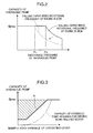
- the capacity of the hydraulic pump 10 is fixed at a maximum capacity q max up to a predetermined discharge pressure P H in which the power requirement of the hydraulic pump 10 does not exceed the output of the engine 2.
- the maximum capacity q max is set to a capacity where the power requirement of the hydraulic pump 10 does not exceed the output of the engine 2 so as long as the discharge pressure of the hydraulic pump 10 is not greater than the predetermined discharge pressure P H .
- the controller 28 gradually decreases the capacity of the hydraulic pump 10 according to the falling curve shown with the solid line in Fig. 2 .
- the falling curve is set to be a curve so that the power requirement of the hydraulic pump 10 sought based on the product of the discharge pressure and capacity of the hydraulic pump 10 will be smaller than the output of the engine 2.
- the predetermined discharge pressure P H and the falling curve that are set in the controller 28 will change according to the rotational frequency of the engine 2. Specifically, if the rotational frequency of the engine 2 is high, the predetermined discharge pressure is P H , and the falling curve is in a state shown with the solid line in Fig. 2 . Meanwhile, if the rotational frequency of the engine 2 decreases, the predetermined discharge pressure consequently decreases to P L as shown in Fig. 2 , and the falling curve also moves to an overall lower value as shown with the broken line in Fig. 2 . Consequently, even if the output of the engine 2 decreases, the power requirement of the hydraulic pump 10 is maintained at a value that is smaller than the output of the engine 2.
- the controller 28 causes the travel-related braking device 20a to apply the parking brake, and sets the switching valves 22a, 22b to the second position P2.
- the travel-related braking device 20a applying the parking brake, the travel motor 32 becomes non-drivable, and the work vehicle becomes a parked state.
- the hydraulic oil will not flow to the travel motor 32 as a result of the travel motor 32 becoming non-drivable.
- the hydraulic oil is supplied to the work-related motor 52a through the branch passage 54a of one side, and the return oil from the work-related motor 52a is subsequently returned to the hydraulic pump 10 through the branch passage 54b of the other side and the other supply/discharge passage 14b.
- the hydraulic oil is supplied to the work-related motor 52a through the reverse path, and the return oil from the work-related motor 52a is returned to the hydraulic pump 10.
- the work-related motor 52a is driven, and the work device is consequently driven.
- the controller 28 increases or decreases the capacity of the hydraulic pump 10 according to the increase or decrease in the manipulated variable of the operating lever 24a of the operating device 24 operated by the operator (second capacity control).
- the capacity of the hydraulic pump 10 is increased in direct proportion to the increase in the manipulated variable of the operating lever 24a.
- the capacity of the hydraulic pump 10 reaches the maximum capacity q max , the capacity of the hydraulic pump 10 is maintained at the maximum capacity q max even if the manipulated variable of the operating lever 24a is further increases.
- the capacity of the hydraulic pump 10 that is actually required for driving the work-related motor 52a in relation to the manipulated variable of the operating lever 24a is shown with the dashed two dotted line in Fig. 3 . Accordingly, if the capacity of the hydraulic pump 10 is not controlled when the work device is driven and the capacity of the hydraulic pump 10 is fixed at the maximum capacity q max , the capacity of the hydraulic pump 10 will increase unnecessarily in relation to the required capacity. Meanwhile, if the capacity of the hydraulic pump 10 is controlled according to the manipulated variable of the operating lever 24a as in the second capacity control, the pump capacity (discharge rate of the hydraulic pump 10) of the hatched portion in Fig. 3 can be reduced.
- the controller 28 selects the foregoing first capacity control or the second capacity control of the hydraulic pump 10, whichever results in a lower discharge pressure of the hydraulic pump 10. Consequently, the power requirement of the hydraulic pump 10 does not exceed the output of the engine 2 even when the work device is driven and, therefore, the engine 2 can be prevented from stopping as in the case when the work vehicle is in a traveling state.
- the controller 28 controls the travel-related braking device 20a to cause the travel-related braking device 20a to make the travel motor 32 drivable, and controls the switching valves 22a, 22b to cause the switching valves 22a, 22b to make the work-related motor 52a non-drivable. Accordingly, with the first embodiment, when the work vehicle is to travel, such work vehicle can travel by driving the wheel drive unit 12 with the hydraulic pressure of the hydraulic oil that is supplied from the hydraulic pump 10 and thereby rotating the wheels 6.
- the controller 28 controls the travel-related braking device 20a to cause the travel-related braking device 20a to make the travel motor 32 non-drivable, and controls the switching valves 22a, 22b to cause the switching valves 22a, 22b to make the work-related motor 52a drivable.
- the work-related motor 52a can be driven with the hydraulic pressure of the hydraulic oil that is supplied from the hydraulic pump 10, and thereby operate the work device.
- the work vehicle can travel based on hydraulic pressure and the first work device can be hydraulically driven.
- the hydraulic oil can be supplied from the hydraulic pump 10 to the travel motor 32 through the closed circuit 14
- the hydraulic oil can also be supplied to the work-related motor 52a from the hydraulic pump 10 via the closed circuit 14 and the branch passage 54.
- a single hydraulic pump 10 is able to supply the hydraulic oil to both the travel motor 32 and the work-related motor 52a.
- the switching valves 22a, 22b are provided to the branch passage 54 of the work device drive circuit 18, the hydraulic oil will not flow through the switching valves 22a, 22b provided to the branch passage 54 when the hydraulic oil is to be supplied to the travel motor 32 through the closed circuit 14 when the work vehicle is in a traveling state.
- the switching control valve provided to the closed circuit when the work vehicle is in a traveling state and, consequently, it is possible to prevent the deterioration of fuel consumption caused by such pressure loss.
- the controller 28 since the controller 28 performs first capacity control of controlling the capacity of the hydraulic pump 10 so that the power requirement of the hydraulic pump 10 does not exceed the output of the engine 2 when the work vehicle is in a traveling state, it is possible to prevent the engine 2 from stopping which is caused by the power requirement of the hydraulic pump 10 exceeding the output of the engine 2 when the work vehicle is in a traveling state.
- the controller 28 selects and performs the first capacity control or second capacity control of increasing or decreasing capacity of the hydraulic pump 10 according to increase or decrease of a manipulated variable of the operating lever 24a operated by the operator, whichever results in a lower discharge pressure of the hydraulic pump 10.
- the capacity of the hydraulic pump 10 is increased or decreased according to the increase or decrease of the manipulated variable of the operating lever 24a operated by the operator, and it is thereby possible to prevent the capacity of the hydraulic pump 10 from becoming an excessively large capacity in relation to the manipulated variable.
- the hydraulic driving member switching unit 22 is configured from a work-related braking device 22d that is capable of applying a brake to the work-related motor 52a, and the switching valves 22a, 22b in the first embodiment are not provided to the branch passage 54.
- the work-related braking device 22d is attached to the work-related motor 52a.
- the work-related motor 52a becomes non-drivable when a brake is applied by the work-related braking device 22d. Meanwhile, the work-related motor 52a becomes drivable when the brake is released by the work-related braking device 22d.
- the controller 28 performs the switching control of causing the work-related braking device 22d to apply a brake to or releasing the applied brake of the work-related motor 52a according to the travel mode selection signal that is input from the travel mode switching device 26.
- the controller 28 when the operator selects the traveling state with the travel mode switching device 26 and a signal designating the traveling state is input from the travel mode switching device 26 into the controller 28, the controller 28 causes the work-related braking device 22d to apply a brake to the work-related motor 52a according to the input signal.
- the work-related motor 52a thereby becomes a non-drivable state when the work vehicle is in a traveling state. And in this state, hardly any hydraulic oil will flow into the work-related motor 52a.
- the controller 28 causes the travel-related braking device 20a to release the parking brake according to a signal designating the traveling state which was input from the travel mode switching device 26.
- the travel motor 32 thereby becomes drivable.
- approximately the entire amount of the hydraulic oil that was discharged from the hydraulic pump 10 to the closed circuit 14 is supplied to the travel motor 32, and the travel motor 32 is driven by the hydraulic pressure of the hydraulic oil.
- the controller 28 causes the work-related braking device 22d to release the brake applied to the work-related motor 52a according to the input signal.
- the work-related motor 52a becomes a drivable state. And in this state, the hydraulic oil can flow into the work-related motor 52a.
- the controller 28 causes the travel-related braking device 20a to apply the parking brake according to a signal designating the parked state which was input from the travel mode switching device 26.
- the travel motor 32 thereby becomes non-drivable.
- the work-related motor 52a When the work-related motor 52a is to be switched between a drivable state and a non-drivable state by switching the supply or non-supply of the hydraulic oil to the work-related motor 52a with the switching valves 22a, 22b provided to the branch passage 54 as with the foregoing first embodiment, the hydraulic oil flows through the switching valves 22a, 22b provided to the branch passage 54 when the work device is driven. Thus, pressure loss of the hydraulic oil will occur.
- the work-related motor 52a is made to be non-drivable by the work-related braking device 22d applying a brake to the work-related motor 52a when the work vehicle is in a traveling state on the one hand, and the work-related motor 52a is made to be drivable by the work-related braking device 22d releasing the brake applied to the work-related motor 52a when the work device is driven.
- pressure loss caused by the hydraulic oil passing through the switching valves 22a, 22b provided to the branch passage 54 as in the foregoing first embodiment will not occur when the work device is driven. Accordingly, with the second embodiment, the fuel consumption can be improved in comparison to the foregoing first embodiment.
- the controller 28 causes a flow regulating valve 56 to regulate the flow direction and flow rate of the hydraulic oil that is supplied to the work-related motor 52a through the branch passage 54.
- the work device drive circuit 18 includes a flow regulating valve 56 that is provided to the branch passage 54. Moreover, the work device drive circuit 18 includes a connecting passage 54c of one side and a connecting passage 54d of another side. One end of the connecting passage 54c of one side is connected to the inlet/outlet 52b of one side of the work-related motor 52a, and one end of the connecting passage 54d of the other side is connected to the inlet/outlet 52c of the other side of the work-related motor 52a.
- the flow regulating valve 56 is connected to the other end of the connecting passage 54c of one side and the other end of the connecting passage 54d of the other side, and an end on the opposite side of the one supply/discharge passage 14a of the branch passage 54a of one side and an end on the opposite side of the other supply/discharge passage 14b of the branch passage 54b of the other side.
- the flow regulating valve 56 can be switched among a neutral position P C which blocks the flow of hydraulic oil between the branch passage 54a of one side and the branch passage 54b of the other side, and the connecting passage 54c of one side and the connecting passage 54d of the other side, a first flow position P f1 which allows the hydraulic oil flowing from the one supply/discharge passage 14a to the branch passage 54a of one side to flow to the connecting passage 54c of one side and which allows the hydraulic oil to flow from the connecting passage 54d of the other side to the branch passage 54b of the other side, and a second flow position P f2 which allows the hydraulic oil flowing from the one supply/discharge passage 14a to the branch passage 54a of one side to flow to the connecting passage 54d of the other side and which allow the hydraulic oil to flow from the connecting passage 54c of one side to the branch passage 54b of the other side.
- the flow regulating valve 56 can be switched based on hydraulic pressure (pilot pressure).
- the flow regulating valve 56 includes two ports 56a, 56b to which the pilot
- the operating device body 24b of the operating device 24 supplies pilot pressure to the port 56a of one side or the port 56b of the other side of the flow regulating valve 56 according to the operating direction of the operating lever 24a.
- a pressure sensor 57 for detecting the pressure in the supply path is connected respectively to the supply path of the pilot pressure from the operating device body 24b to the port 56a of one side and the supply path of the pilot pressure from the operating device body 24b to the port 56b of the other side. Both pressure sensors 57 send a signal showing the detected pressure to the controller 28.
- the operating device body 24b does not supply the pilot pressure to either the port 56a of one side or the port 56b of the other side when the operating lever 24a is in the neutral position.
- the flow regulating valve 56 becomes the neutral position P C , and, even if the hydraulic oil that was discharged from the hydraulic pump 10 to the one supply/discharge passage 14a in a parked state flows into the branch passage 54a of one side, such hydraulic oil is not supplied to the work-related motor 52a.
- This hydraulic oil flows from the branch passage 54a of one side to the hydraulic oil tank T through the flow regulating valve 56.
- the operating device body 24b supplies the pilot pressure to the port 56a of one side.
- the flow regulating valve 56 thereby moves from the neutral position P C to the first flow position P f1 side.
- the hydraulic oil that was discharged from the hydraulic pump 10 to the one supply/discharge passage 14a in a parked state and flowed into the branch passage 54a of one side is supplied to the work-related motor 52a through the connecting passage 54c of one side.
- the return oil from the work-related motor 52a is returned from the connecting passage 54d of the other side to the other supply/discharge passage 14b through the branch passage 54b of the other side.
- the work-related motor 52a rotates positively.
- the pilot pressure that is supplied from the operating device body 24b to the port 56a of one side is increased or decreased according to the manipulated variable toward one side from the neutral position of the operating lever 24a. Specifically, when the manipulated variable toward one side of the operating lever 24a increases, the pilot pressure that is supplied from the operating device body 24b to the port 56a of one side increases. If the pilot pressures that is supplied to the port 56a of one side increases, the amount of movement from the neutral position P C of the flow regulating valve 56 to the first flow position P f1 side increases.
- the operating device body 24b supplies the pilot pressure to the port 56b of the other side.
- the flow regulating valve 56 thereby moves from the neutral position P C to the second flow position P f2 side.
- the hydraulic oil that was discharged from the hydraulic pump 10 to the one supply/discharge passage 14a in a parked state that flowed into the branch passage 54a of one side is supplied to the work-related motor 52a through the connecting passage 54d of the other side.
- the return oil from the work-related motor 52a is returned to the branch passage 54b of the other side through the connecting passage 54c of one side.
- the work-related motor 52a rotates negatively.
- the pilot pressure that was supplied from the operating device body 24b to the port 56b of the other side is increased or decreased according to the manipulated variable toward the other side from the neutral position of the operating lever 24a.
- the amount of hydraulic oil that is supplied to the work-related motor 52a increases or decreases and, consequently, the rotational speed of the work-related motor 52a in the reverse rotating direction increases or decreases.
- the rotational speed of the work-related motor 52a can be controlled according to the manipulated variable of the operating lever 24a operated by the operator and, consequently, the drive speed and the like of the work device can be controlled according to the manipulated variable of the operating lever 24a operated by the operator.
- the flow regulating valve 56 detailed flow rate control can be performed in comparison to the flow rate control of the hydraulic oil by controlling the discharge rate of the hydraulic pump 10, and the flow regulating valve 56 has superior responsiveness.
- the third embodiment it is possible to accurately regulate the flow rate of the hydraulic oil supplied to the work-related motor 52a according to the minimal operation of the operating lever 24a even if the manipulated variable of the operating lever 24a operated by the operator is minimal, and improve the responsiveness of regulating the flow rate of the hydraulic oil supplied to the work-related motor 52a in relation to the operation of the operating lever 24a.
- the configuration is such that the hydraulic oil to the work-related motor 52a can only be supplied from the one supply/discharge passage 14a of the closed circuit 14, and the flow rate of the hydraulic oil to be supplied to the work-related motor 52a can be regulated with the flow regulating valve 56.
- predetermined back pressure is applied to the return oil from the work-related motor 52a and returned to the other supply/discharge passage 14b of the closed circuit 14.
- the configuration of the work vehicle according to the fourth embodiment is basically the same as the configuration of the work vehicle according to the foregoing third embodiment.
- the part where the flow direction and flow rate of the hydraulic oil from the branch passage 54a of one side to the work-related motor 52a in a parked state are controlled with the flow regulating valve 56 according to the operation of the operating lever 24a by the operator is configured the same as the corresponding part of the foregoing third embodiment.
- the fourth embodiment only the branch passage 54a of one side is covered by the concept of the work-related supply route of the present invention.
- the hydraulic oil that is supplied to the work-related motor 52a is only the hydraulic oil that is discharged from the hydraulic pump 10 to the one supply/discharge passage 14a and which flows from the one supply/discharge passage 14a through the branch passage 54a of one side.
- the work-related return oil passage 54e is connecting the flow regulating valve 56 and the other supply/discharge passage 14b.
- the switching valve 22b of the other side of the foregoing third embodiment is not provided to the work-related return oil passage 54e.
- a back pressure generating device 82 is connected to the work-related return oil passage 54e.
- a check valve 83 for preventing the hydraulic oil from flowing backward from the other supply/discharge passage 14b side to the flow regulating valve 56 side is provided to a part that is closer to the other supply/discharge passage 14b side than that the connection of the back pressure generating device 82 of the branch passage 54b of the other side.
- the back pressure generating device 82 includes an escape passage 82a and a back pressure check valve 82b.
- the escape passage 82a is branched from the work-related return oil passage 54e and connected to the hydraulic oil tank T.
- the back pressure check valve 82b is provided to the escape passage 82a.
- the return oil to which the back pressure was applied is returned to the other supply/discharge passage 14b through the check valve 83. Since the setting pressure of the back pressure check valve 82b is set to be greater than the hydraulic pressure in the other supply/discharge passage 14b, a back pressure that is greater than the hydraulic pressure in the other supply/discharge passage 14b is also applied to the return oil, and the return oil is thereby returned to the other supply/discharge passage 14b.
- the charge circuit 16 includes a filter 51 for filtering the hydraulic oil that flows through the charge oil passage 38.
- the filter 51 is provided to the discharge passage 38b of the charge oil passage 38. The hydraulic oil discharged from the charge pump 36 to the discharge passage 38b is thereby filtered with the filter 51, and subsequently introduced into the closed circuit 14.
- the fourth embodiment is able to achieve the same effects as the foregoing third embodiment.
- the return oil from the work-related motor 52a can be reliably returned to the closed circuit 14. Consequently, it is possible to prevent the occurrence of cavitation in the closed circuit 14 caused by the amount of return oil from the work-related motor 52a being insufficient.
- the hydraulic oil that is discharged from the charge pump can be introduced into the closed circuit after being filtered with the filter of the charge circuit, clean hydraulic oil can be supplied from the charge circuit to the closed circuit. Consequently, it is possible to prevent hydraulic oil containing foreign matter from being sent from the closed circuit 14 to the respective devices and, consequently, it is possible to prevent the respective devices from becoming damaged or malfunctioning.
- the flow regulating valve 56 is controlled by the controller 28 causing the reducing valves 85, 86 to control the pilot pressure supplied to the flow regulating valve 56, and the supply or non-supply of the hydraulic oil to the work-related motor 52a is thereby switched.
- the flow regulating valve 56 is covered by the concept of the hydraulic driving member switching unit of the present invention.
- the configuration of the work vehicle according to the fifth embodiment is a configuration where the switching valve 22a of one side is omitted from the work vehicle of the foregoing fourth embodiment, and adding a first reducing valve 85, a second reducing valve 86, and a work-related braking device 22d.
- the first reducing valve 85 is provided to the supply path of the pilot pressure from the operating device body 24b to the port 56a of one side of the flow regulating valve 56.
- the second reducing valve 86 is provided to the supply path of the pilot pressure from the operating device body 24b to the port 56b of the other side of the flow regulating valve 56.
- the controller 28 controls the first reducing valve 85 and the second reducing valve 86 according to the travel mode that was selected by the operator with the travel mode switching device 26. Specifically, when the operator selects the traveling state with the travel mode switching device 26 and a signal designating the traveling state is input from the travel mode switching device 26 into the controller 28, the controller 28 causes both reducing valves 85, 86 to depressurize the pilot pressure that is supplied from the operating device body 24b to the flow regulating valve 56 according to the input signal.
- the controller 28 controls the level of depressurization by the first reducing valve 85 and the level of depressurization by the second reducing valve 86 so that the pilot pressure that is supplied from the operating device body 24b to the port 56a of one side and the pilot pressure that is supplied from the operating device body 24b to the port 56b of the other side will be an equal pressure.
- the flow regulating valve 56 will be forced to the neutral position P C regardless of the operational status of the operating device 24. Consequently, since the flow of the hydraulic oil is blocked with the flow regulating valve 56 and the hydraulic oil is no longer supplied to the work-related motor 52a, the work-related motor 52a becomes non-drivable.
- the controller 28 causes both reducing valves 85, 86 to discontinue the depressurization of the pilot pressure according to the input signal.
- the pilot pressure according to the operation of the operating lever 24a by the operation is supplied from the operating device body 24b to the respective ports 56a, 56b of the flow regulating valve 56. Consequently, as with the parked state in the foregoing fifth embodiment, the flow regulating valve 56 is switched among the neutral position P C and the first flow position P f1 and the second flow position P f2 according to the operating direction and manipulated variable of the operating lever 24a.
- the fifth embodiment is able to achieve the same effects as the foregoing third embodiment.
- the flow regulating valve 56 is able to regulate the flow rate of the hydraulic oil as well as switch between the supply and non-supply of the hydraulic oil to the work-related motor 52a, the number of components can be reduced in comparison to a case of separately providing the switching valve and the flow regulating valve.
- the work vehicle according to the sixth embodiment is provided with a second work device (not shown) in addition to the first work device (not shown), and the amount of hydraulic oil that became a surplus (surplus oil) when supplied to the second work device can be supplied to the hydraulic driving member 52 of the first work device.
- the work vehicle according to the sixth embodiment is configured the same as the work vehicle of the foregoing fourth embodiment.
- the work device, the flow regulating valve 56, and the operating device 24 of the foregoing fourth embodiment correspond to the first work device, the first flow regulating valve 56, and the first operating device 24 in the sixth embodiment.
- the work vehicle of the sixth embodiment additionally includes a second work device, a work-related hydraulic pump 88, a hydraulic oil circuit 89, and a second operating device 90.
- the second work device is driven by hydraulic pressure, and is configured to perform predetermined work that is different from the first work device.
- the second work device includes a hydraulic driving member 91 that operates by being supplied with hydraulic pressure.
- the hydraulic driving member 91 is configured from a hydraulic cylinder 91a, and the second work device is operated when the hydraulic cylinder 91a is driven.
- the work-related hydraulic pump 88 is driven by the engine 2 and discharges hydraulic oil. Specifically, the work-related hydraulic pump 88 is connected to the power divider 8. The driving force of the engine 2 is thereby distributed to the work-related hydraulic pump 88 by the power divider 8, and the work-related hydraulic pump 88 is consequently driven. Moreover, the work-related hydraulic pump 88 is a variable displacement-type hydraulic pump, and its capacity is controlled by the controller 28.
- the hydraulic oil circuit 89 is configured to be capable of supplying the hydraulic oil that was discharged from the work-related hydraulic pump 88 to the hydraulic driving member 91 of the second work device.
- the hydraulic oil circuit 89 includes a second flow regulating valve 92, a supply route 93, a supply/discharge passage 94 of one side, a supply/discharge passage 95 of another side, a tank discharge passage 96, a surplus oil passage 97, an escape passage 98, an unloading valve 99, and a check valve 100.
- the configuration of the second flow regulating valve 92 is the same as the flow regulating valve 56 of the foregoing third embodiment.
- One end of the supply route 93 is connected to a discharge opening of the work-related hydraulic pump 88, and another end of the supply route 93 is connected to the second flow regulating valve 92.
- One end of the supply/discharge passage 94 of one side is connected to the second flow regulating valve 92, and the other end of the supply/discharge passage 94 of one side is connected to the inlet/outlet 91b of one side of the hydraulic cylinder 91a.
- One end of the supply/discharge passage 95 of the other side is connected to the second flow regulating valve 92, and the other end of the supply/discharge passage 95 of the other side is connected to the inlet/outlet 91c of the other side of the hydraulic cylinder 91a.
- One end of the tank discharge passage 96 is connected to the second flow regulating valve 92 and the other end of the tank discharge passage 96 is connected to the hydraulic oil tank T.
- the surplus oil passage 97 is used for flowing, to the branch passage 54a of one side, hydraulic oil that is made surplus relative to an amount of the hydraulic oil supplied to the hydraulic driving member 91 of the second work device, of the hydraulic oil discharged from the work-related hydraulic pump 88.
- One end of the surplus oil passage 97 is connected to the second flow regulating valve 92, and the other end of the surplus oil passage 97 is connected to a part on the downstream side of the switching valve 22a of one side of the branch passage 54a of one side.
- One end of the escape passage 98 is connected to the surplus oil passage 97, and the other end of the escape passage 98 is connected to the hydraulic oil tank T.
- the unloading valve 99 is provided to the escape passage 98.
- the unloading valve 99 can be switched between a discharge permitting position P A that permits the flow of the hydraulic oil to the hydraulic oil tank T side, and a discharge blocking position P B that blocks the flow of such hydraulic oil.
- the unloading valve 99 is a solenoid valve that is switched by the controller 28.
- the check valve 100 is provided to a part that is closer to the branch passage 54a of one side than the portion to which the escape passage 98 is connected of the surplus oil passage 97.
- the check valve 100 blocks the hydraulic oil from flowing backward from the branch passage 54a of one side to the second flow regulating valve 92 side through the surplus oil passage 97.
- the configuration of the second operating device 90 is the same as the operating device 24 of the foregoing third embodiment.
- pressure sensors 101 are respectively connected to the supply path of the pilot pressure from the operating device body 90b of the second operating device 90 to the port 92a of one side of the second flow regulating valve 92, and the supply path of the pilot pressure from the operating device body 90b of the second operating device 90 to the port 92b of the other side of the second flow regulating valve 92. Both pressure sensors 101 respectively detect the pressure in the supply path to which they are connected, and send a signal showing the detected pressure to the controller 28.
- the work-related hydraulic pump 88 is operated when the engine 2 is driven, and hydraulic oil is thereby discharged from the work-related hydraulic pump 88 to the supply route 93.
- the second flow regulating valve 92 is switched among the neutral position P C and the first flow position P f1 and the second flow position P f2 according to the operation of the operating lever 90a of the second operating device 90 by the operator.
- the operation in the foregoing case is the same as the operation of the flow regulating valve 56 of the foregoing fifth embodiment.
- the hydraulic oil flows from the supply route 93 to the supply/discharge passage 94 of one side and is supplied to the inlet/outlet 91b of one side of the hydraulic cylinder 91a.
- the hydraulic cylinder 91a is thereby operated, and the hydraulic oil is consequently discharged from the inlet/outlet 91c of the other side.
- the discharged hydraulic oil passes through the supply/discharge passage 95 of the other side and the tank discharge passage 96 and then flows to the hydraulic oil tank T.
- the hydraulic oil (surplus oil) exceeding the flow rate that is restricted with the second flow regulating valve 92 of the hydraulic oil that was discharged from the work-related hydraulic pump 88 flows to the surplus oil passage 97.
- the hydraulic oil flows from the supply route 93 to the supply/discharge passage 95 of the other side and is supplied to the inlet/outlet 91c of the other side of the hydraulic cylinder 91a.
- the hydraulic cylinder 91a is thereby operated, and the hydraulic oil is consequently discharged from the inlet/outlet 91b of one side.
- the discharged hydraulic oil passes through the tank discharge passage 96 and flows to the hydraulic oil tank T.
- the hydraulic oil (surplus oil) exceeding the flow rate that is restricted with the second flow regulating valve 92 of the hydraulic oil that was discharged from the work-related hydraulic pump 88 flows to the surplus oil passage 97.
- the controller 28 sets the unloading valve 99 to a discharge blocking position P B .
- the hydraulic oil that flowed to the surplus oil passage 97 is thereby introduced into the branch passage 54a of one side without being released to the hydraulic oil tank T through the escape passage 98. Consequently, even if the operator selected the traveling state with the travel mode switching device 26 and the hydraulic oil is not supplied from the closed circuit 14 to the work-related motor 52a side through the branch passage 54a of one side, the work-related motor 52a becomes drivable with the hydraulic pressure of the hydraulic oil that is supplied through the surplus oil passage 97.
- the controller 28 sets the unloading valve 99 to a discharge permitting position P A .
- the hydraulic oil that flowed to the surplus oil passage 97 will thereby flow to the hydraulic oil tank T through the escape passage 98.
- the second work device can be driven by supplying the hydraulic oil from the work-related hydraulic pump 88 to the hydraulic cylinder 91a of the second work device.
- work that is different from the foregoing work can be performed by the second work device in the work vehicle.
- the sixth embodiment even in a case where the switching valve 22a of one side is in the state of the first position P1 and the flow of the hydraulic oil from the closed circuit 14 to the work-related motor 52a through the branch passage 54a of one side is blocked when the work vehicle is in a traveling state, it is possible to supply the surplus oil to the work-related motor 52a and drive the work-related motor 52a. Accordingly, with the sixth embodiment, the travel of the work vehicle and the drive of the first work device and second work device can be simultaneously performed.
- a single work-related hydraulic pump is able to supply the hydraulic oil to both the hydraulic cylinder 91a of the second work device and the work-related motor 52a of the first work device when the work vehicle is in a traveling state.
- the configuration of the work vehicle can be simplified.
- the return oil from the work-related motor 52a is introduced to a part between the charge pump 36 and the filter 51 of the charge circuit 16.
- an end on the opposite side of the first flow regulating valve 56 of the work-related return oil passage 54e is connected to a part between the charge pump 36 and the filter 51 of the discharge passage 38b of the charge oil passage 38.
- a back pressure generating device 82 is connected to the work-related return oil passage 54e, and, based on this back pressure generating device 82, the back pressure that is applied to the return oil flowing through the work-related return oil passage 54e becomes a back pressure that is greater than the setting pressure of the charge circuit 16.
- the setting pressure of the back pressure check valve 82b is greater than the pressure that is applied to the hydraulic oil in the charge circuit 16.
- the return oil from the work-related motor 52a can be returned to the closed circuit 14 after being filtered with the filter 51 of the charge circuit 16, the return oil from the work-related motor 52a can be returned to the closed circuit 14 in a clean state. Accordingly, with the seventh embodiment, it is possible to prevent hydraulic oil containing foreign matter from being sent from the closed circuit 14 to the respective devices and, consequently, it is possible to prevent the respective devices from becoming damaged or malfunctioning.
- the configuration can be simplified in comparison to the configuration providing a filter for filtering the return oil from the work-related motor 52a separately from the filter 51 of the charge circuit 16.
- the back pressure generating device 82 can be used to apply a back pressure to the return oil from the work-related motor 52a that is greater than the setting pressure of the charge circuit 16, and thereby introduce the return oil to the charge circuit 16.
- a back pressure to the return oil from the work-related motor 52a that is greater than the setting pressure of the charge circuit 16, and thereby introduce the return oil to the charge circuit 16.
- the hydraulic driving member switching unit 22 may also be a work-related motor capacity regulating unit (not shown) that is provided to the work-related motor 52a.
- the work-related motor capacity regulating unit is used for regulating the capacity of the work-related motor 52a.
- the controller 28 controls the work-related motor capacity regulating unit to cause the capacity of the work-related motor 52a to be 0.
- the work-related motor 52a thereby becomes non-drivable.
- approximately the entire amount of the hydraulic oil that was discharged from the hydraulic pump 10 to the closed circuit 14 is supplied to the travel motor 32. Consequently, the travel motor 32 is driven.
- the controller 28 controls the work-related motor capacity regulating unit to cause the capacity of the work-related motor 52a to be a predetermined capacity that is greater than 0.
- the work-related motor 52a thereby becomes drivable.
- the hydraulic oil flows into the work-related motor 52a and the work-related motor 52a is driven.
- the configuration of the work vehicle can be simplified in comparison to the configuration of switching the work-related motor 52a between a drivable state and a non-drivable state by providing a switching valve for switching between the supply and non-supply of the hydraulic oil to the work-related motor 52a or a braking device for applying a brake to the work-related motor 52a.
- the wheel drive unit switching unit 20 may be a travel-related motor capacity regulating unit (not shown) that is provided to the travel motor 32.
- the travel-related motor capacity regulating unit is used for regulating the capacity of the travel motor 32.
- the controller 28 controls the travel-related motor capacity regulating unit to cause the capacity of the travel motor 32 to be 0.
- the travel motor 32 thereby becomes non-drivable.
- approximately the entire amount of the hydraulic oil that was discharged from the hydraulic pump 10 to the closed circuit 14 is supplied to the work-related motor 52a. Consequently, the work-related motor 52a is driven.
- the controller 28 controls the travel-related motor capacity regulating unit to cause the capacity of the travel motor 32 to be a predetermined capacity that is greater than 0.
- the travel motor 32 thereby becomes drivable, the hydraulic oil flows from the closed circuit to the travel motor 32, and the travel motor 32 is thereby driven.
- the hydraulic work vehicle includes an engine, wheels, a first work device capable of performing predetermined work, a hydraulic pump that is driven by the engine and discharges hydraulic oil, a wheel drive unit that is driven by hydraulic pressure of hydraulic oil supplied from the hydraulic pump to rotate the wheel, a closed circuit that connects the hydraulic pump and the wheel drive unit and circulates hydraulic oil between the hydraulic pump and the wheel drive unit, a work device drive circuit that includes a hydraulic driving member for driving the first work device and is branched from the closed circuit so that hydraulic oil for driving the hydraulic driving member can flow in the work device drive circuit from the closed circuit, a wheel drive unit switching unit that is provided to the wheel drive unit and capable of switching the wheel drive unit between a wheel driving state and a wheel non-driving state, a hydraulic driving member switching unit that is provided to the work device drive circuit and capable of switching the hydraulic driving member between a work device driving state and a work device non-driving state, and a control unit for controlling the wheel drive unit switching unit to cause the wheel
- This hydraulic work vehicle includes a wheel drive unit that is driven by hydraulic pressure of hydraulic oil supplied from the hydraulic pump through the closed circuit and rotates the wheel, and a work device drive circuit that includes a hydraulic driving member for driving the first work device and is branched from the closed circuit so that hydraulic oil can flow in from the closed circuit.
- the control unit controls the wheel drive unit switching unit to cause the wheel drive unit to be in the wheel drivinge state, and controls the hydraulic driving member switching unit to cause the hydraulic driving member to be in the work device non-driving state. Accordingly, when the work vehicle is to travel, such work vehicle can travel by driving the wheel drive unit with hydraulic pressure of hydraulic oil that is supplied from the hydraulic pump and thereby rotating the wheel.
- the control unit controls the wheel drive unit switching unit to cause the wheel drive unit to be in the wheel non-driving state and controls the hydraulic driving member switching unit to cause the hydraulic driving member to be in the work device driving state.
- the hydraulic driving member is driven with the hydraulic pressure of the hydraulic oil that is supplied from the hydraulic pump, and the first work device can thereby be driven by the hydraulic driving member. Accordingly, with this hydraulic work vehicle, the work vehicle can travel based on hydraulic pressure and the first work device can be hydraulically driven.
- the hydraulic oil can be supplied from the hydraulic pump to the wheel drive unit through the closed circuit on the one hand, the hydraulic oil can also be supplied to the hydraulic driving member by causing the hydraulic oil to flow into the work device drive circuit from the hydraulic pump via the closed circuit.
- a single hydraulic pump is able to supply the hydraulic oil to both the wheel drive unit and the hydraulic driving member of the work device drive circuit.
- this hydraulic work vehicle is able to prevent the deterioration of fuel consumption caused by the idling of the hydraulic pump for supplying the hydraulic oil to the work device when the work vehicle is in a traveling state.
- the switching control valve for respectively switching the wheel drive unit and the hydraulic driving member between a drivable state and a non-drivable state by switching whether to supply the hydraulic oil, which is discharged from the hydraulic pump to the closed circuit, to the wheel drive unit or the hydraulic driving member is provided to the closed circuit, the hydraulic oil is supplied to the wheel drive unit through the switching control valve provided to the closed circuit when the work vehicle is in a traveling state.
- pressure loss will occur as a result of the hydraulic oil passing through the switching control valve.
- the hydraulic driving member switching unit is provided to the work device drive circuit, even if the hydraulic driving member switching unit is a switching control valve that switches the flow of the hydraulic oil, the hydraulic oil will not flow by passing through the switching control valve provided to the work device drive circuit when the hydraulic oil is to be supplied to the wheel drive unit through the closed circuit when the work vehicle is in a traveling state.
- the hydraulic driving member switching unit is a switching control valve that switches the flow of the hydraulic oil
- the hydraulic oil will not flow by passing through the switching control valve provided to the work device drive circuit when the hydraulic oil is to be supplied to the wheel drive unit through the closed circuit when the work vehicle is in a traveling state.
- this hydraulic work vehicle it is possible to prevent the deterioration of fuel consumption during the travel of the work vehicle while enabling the work vehicle to travel based on hydraulic pressure and the first work device to be hydraulically driven.
- the work device drive circuit may include a work-related supply route that branches from the closed circuit so as to lead hydraulic oil supplied from the closed circuit to the hydraulic driving member
- the hydraulic driving member switching unit may be a switching valve that is provided to the work-related supply route and capable of being switched between a first position of blocking hydraulic oil from flowing from the closed circuit to the hydraulic driving member through the work-related supply route, and a second position of allowing hydraulic oil to flow from the closed circuit to the hydraulic driving member through the work-related supply route
- the control unit may cause the switching valve to be in the first position when the hydraulic work vehicle is in a traveling state and cause the switching valve to be in the second position when the first work device is driven.
- the control unit since the control unit causes the switching value to be in the first position when the work vehicle is in a traveling state, the hydraulic oil will not be supplied to the hydraulic driving member. Consequently, the hydraulic driving member becomes non-drivable. Meanwhile, since the control unit causes the switching valve to be in the second position when the first work device is driven, the hydraulic oil is supplied to the hydraulic driving member. Consequently, the hydraulic driving member becomes drivable.
- the hydraulic work vehicle further includes an operating device that is operated for designating an operation of the first work device, and a flow regulating valve that is provided to the work-related supply route and capable of regulating a flow rate of hydraulic oil, wherein the control unit controls a flow rate of hydraulic oil supplied to the hydraulic driving member by controlling a flow tolerance of hydraulic oil by the flow regulating valve according to a manipulated variable of the operating device.
- the flow rate of the hydraulic oil that is supplied to the hydraulic driving member can be controlled according to the manipulated variable of the operating device operated by the operator, it is possible to control the drive speed and the like of the first work device according to the manipulated variable of the operating device operated by the operator.
- the capacity control of a hydraulic pump entails a problem in that the responsiveness is inferior in relation to the sudden operation of the operating device.
- a flow regulating valve is suitable for the detailed flow rate control of hydraulic oil in comparison to a hydraulic pump, and also has superior responsiveness.
- the control unit causes the flow regulating valve to control the flow rate of the hydraulic oil supplied to the hydraulic driving member according to the manipulated variable of the operating device as with the present configuration, it is possible to accurately regulate the flow rate of the hydraulic oil supplied to the hydraulic driving member according to the minimal operation of the operating device even if the manipulated variable of the operating device is minimal, and improve the responsiveness of regulating the flow rate of the hydraulic oil supplied to the hydraulic driving member in relation to the operation of the operating device.
- the hydraulic work vehicle further includes an operating device that is operated by an operator for designating an operation of the first work device, wherein the switching valve is configured to be capable of regulating a flow rate of hydraulic oil that flows through the switching valve, and the control unit controls a flow rate of hydraulic oil supplied to the hydraulic driving member by controlling a flow tolerance of hydraulic oil of the switching valve according to a manipulated variable of the operating device operated by the operator.
- the switching value provided to the work-related supply route is equipped with a function for regulating the flow rate of the hydraulic oil as in the present configuration, as with the case of using the foregoing flow regulating valve, it is possible to accurately regulate the flow rate of the hydraulic oil supplied to the hydraulic driving member according to the minimal operation of the operating device even if the manipulated variable of the operating device is minimal, and improve the responsiveness of regulating the flow rate of the hydraulic oil supplied to the hydraulic driving member in relation to the operation of the operating device.
- the switching valve since the switching valve also functions as the flow regulating valve for regulating the flow rate of the hydraulic oil to the hydraulic driving member, the number of components can be reduced in comparison to a case of separately providing the switching valve and the flow regulating valve.
- the hydraulic work vehicle further includes a second work device that is driven by hydraulic pressure to perform predetermined work, a work-related hydraulic pump that is driven by the engine to discharge hydraulic oil, and a hydraulic oil circuit that is capable of supplying hydraulic oil discharged from the work-related hydraulic pump to the second work device, wherein the hydraulic oil circuit includes a surplus oil passage that leads, to the work-related supply route, hydraulic oil that is made surplus relative to an amount of the hydraulic oil supplied to the second work device, of the hydraulic oil discharged from the work-related hydraulic pump, and the surplus oil passage is connected to the work-related supply route at a position downstream of the switching valve in a flow direction of hydraulic oil.
- the hydraulic oil can be supplied from the work-related hydraulic pump to the second work device to drive the second work device.
- work that is different from the foregoing work can be performed by the second work device in the work vehicle.
- the surplus oil passage for flowing hydraulic oil that is surplus relative to an amount of the hydraulic oil supplied to the second work device, of the hydraulic oil discharged from the work-related hydraulic pump is connected to a position in the work-related supply route, on a downstream side of the switching value in a flow direction of hydraulic oil.
- the hydraulic driving member may be a work-related hydraulic motor for driving the first work device
- the hydraulic driving member switching unit may be a work-related braking device that is attached to the work-related hydraulic motor and capable of applying a brake to the work-related hydraulic motor
- the control unit may cause the work-related braking device to apply a brake to the work-related hydraulic motor when the hydraulic work vehicle is in a traveling state and cause the work-related braking device to release the brake applied to the work-related hydraulic motor when the first work device is driven.
- the control unit since the control unit causes the work-related braking device to apply a brake to the work-related hydraulic motor when the work vehicle is in a traveling state, the work-related hydraulic motor becomes non-drivable. Meanwhile, since the control unit causes the work-related braking device to release the brake applied to the work-related hydraulic motor when the first work device is driven, the work-related hydraulic motor becomes drivable.
- the hydraulic driving member may be a variable displacement-type work-related hydraulic motor for driving the first work device
- the hydraulic driving member switching unit may be a work-related motor capacity regulating unit that is provided to the work-related hydraulic motor and capable of regulating capacity of the work-related hydraulic motor
- the control unit may cause the work-related motor capacity regulating unit to set the capacity of the work-related hydraulic motor to 0 when the hydraulic work vehicle is in a traveling state and cause the work-related motor capacity regulating unit to set the capacity of the work-related hydraulic motor to be a specific capacity that is greater than 0 when the first work device is driven.
- the control unit controls the work-related motor capacity regulating unit to cause the capacity of the work-related hydraulic motor to be 0 when the work vehicle is in a traveling state, the work-related hydraulic motor becomes non-drivable.
- the control unit controls the work-related motor capacity regulating unit to cause the capacity of the work-related hydraulic motor to be a specific capacity that is greater than 0 when the first work device is driven, the work-related hydraulic motor becomes drivable.
- the configuration can be simplified in comparison to the configuration of switching the work-related hydraulic motor between a drivable state and a non-drivable state by providing a switching valve for switching between the supply and non-supply of the hydraulic oil to the work-related hydraulic motor or a braking device for applying a brake to the work-related hydraulic motor.
- the wheel drive unit may include a travel-related hydraulic motor that is connected to the closed circuit and generates driving force for rotating the wheel as a result of being supplied with hydraulic oil through the closed circuit
- the wheel drive unit switching unit may be a travel-related braking device that is capable of applying a brake to the travel-related hydraulic motor
- the control unit may cause the travel-related braking device to apply a brake to the travel-related hydraulic motor when the first work device is driven and cause the travel-related braking device to release the brake applied to the travel-related hydraulic motor when the hydraulic work vehicle is in a traveling state.
- the control unit since the control unit causes the travel-related braking device to apply a brake to the travel-related hydraulic motor when the first work device is driven, the travel-related hydraulic motor becomes non-drivable. Meanwhile, since the control unit causes the travel-related braking device to release the brake applied to the travel-related hydraulic motor when the work vehicle is in a traveling state, the travel-related hydraulic motor becomes drivable.
- the wheel drive unit may include a variable displacement-type travel-related hydraulic motor that is connected to the closed circuit and generates driving force for rotating the wheel as a result of being supplied with hydraulic oil through the closed circuit
- the wheel drive unit switching unit may be a travel-related motor capacity regulating unit that is provided to the travel-related hydraulic motor and capable of regulating capacity of the travel-related hydraulic motor
- the control unit may cause the travel-related motor capacity regulating unit to set the capacity of the travel-related hydraulic motor to 0 when the first work device is driven and causes the travel-related motor capacity regulating unit to set the capacity of the travel-related hydraulic motor to a specific capacity that is greater than 0 when the hydraulic work vehicle is in a traveling state.
- the control unit controls the travel-related motor capacity regulating unit to cause the capacity of the travel-related hydraulic motor to be 0 when the first work device is driven, the travel-related hydraulic motor becomes non-drivable.
- the control unit controls the travel-related motor capacity regulating unit to cause the capacity of the travel-related hydraulic motor to be a specific capacity that is greater than 0 when the work vehicle is in a traveling state, the travel-related hydraulic motor becomes drivable.
- the hydraulic work vehicle further includes an operating device that is operated by an operator for designating an operation of the first work device, wherein the hydraulic pump is a variable displacement-type, and when the hydraulic work vehicle is in a traveling state, the control unit performs first capacity control of controlling capacity of the hydraulic pump so that power required for driving the hydraulic pump does not exceed an output of the engine, and when the first work device is driven, the control unit selects and performs the first capacity control or second capacity control of increasing or decreasing the capacity of the hydraulic pump according to increase or decrease of a manipulated variable of the operating device operated by the operator, whichever results in a lower discharge pressure of the hydraulic pump.
- the hydraulic pump is a variable displacement-type
- the engine will stop if the power that is required for driving the hydraulic pump when the work vehicle is in a traveling state exceeds the output of the engine.
- the capacity of the hydraulic pump is controlled so that the power that is required for driving the hydraulic pump when the work vehicle is in a traveling state does not exceed the output of the engine, it is possible to prevent the engine from stopping.
- the first capacity control of the hydraulic pump for preventing the power required for driving the hydraulic pump from exceeding the output of the engine or the second capacity control of increasing or decreasing capacity of the hydraulic pump according to increase or decrease of a manipulated variable of the operating device operated by the operator is selected, whichever results in a lower discharge pressure of the hydraulic pump.
- the capacity of the hydraulic pump is increased or decreased according to the increase or decrease of the manipulated variable of the operating device operated by the operator, and it is thereby possible to prevent the capacity of the hydraulic pump from becoming an excessively large capacity in relation to the manipulated variable. Since it is thereby possible to prevent the power required for driving the hydraulic pump from becoming unnecessarily large as a result of the capacity of the hydraulic pump from becoming excessive in relation to the manipulated variable, it is possible to improve the fuel consumption.
- the foregoing hydraulic work vehicle further includes a charge circuit that is capable of introducing hydraulic oil to the closed circuit at a predetermined setting pressure
- the work device drive circuit includes a work-related return oil passage that is capable of introducing return oil from the hydraulic driving member to the charge circuit, and a back pressure generating device that is provided to the work-related return oil passage and generates a back pressure that is greater than the predetermined setting pressure in return oil flowing through the work-related return oil passage.
- the amount of return oil from the hydraulic driving member of the work device drive circuit to the closed circuit is insufficient, the amount of hydraulic oil circulating in the closed circuit may become insufficient and cause cavitation in the closed circuit.
- a work-related return oil passage capable of introducing the return oil from the hydraulic driving member to the charge circuit is provided, and a back pressure generating device that generates back pressure to the hydraulic oil flowing through the work-related return oil passage that is greater than the setting pressure that is applied to the hydraulic oil in the charge circuit, the return oil from the hydraulic driving member can be reliably returned to the closed circuit from the work-related return oil passage through the charge circuit.
- the charge circuit includes a charge pump that is driven by the engine and discharges hydraulic oil, a charge oil passage that connects a discharge opening of the charge pump and the closed circuit, and a filter that is provided to the charge oil passage and used for filtering hydraulic oil flowing through the charge oil passage, and the work-related return oil passage is connected to a part between the charge pump and the filter, of the charge oil passage.
- the hydraulic oil that is discharged from the charge pump can be introduced into the closed circuit after being filtered with the filter of the charge circuit.
- clean hydraulic oil can be supplied from the charge circuit to the closed circuit.
- the work-related return oil passage is connected to a part between the charge pump and the filter, of the charge oil passage, the return oil from the hydraulic driving member can be returned to the closed circuit after being filtered with the filter of the charge circuit.
- the return oil from the hydraulic driving member can be returned to the closed circuit in a clean state. Accordingly, with this configuration, it is possible to prevent hydraulic oil containing foreign matter from being sent from the closed circuit to the respective devices and, consequently, it is possible to prevent the respective devices from becoming damaged or malfunctioning.
- the configuration can be simplified in comparison to the configuration providing a filter for filtering the return oil from the hydraulic driving member separately from the filter of the charge circuit.
- the hydraulic work vehicle of the present invention includes: an engine; wheels; a first work device capable of performing predetermined work; a hydraulic pump that is driven by the engine and discharges hydraulic oil; a wheel drive unit that is driven by hydraulic pressure of hydraulic oil supplied from the hydraulic pump to rotate the wheel; a closed circuit that connects the hydraulic pump and the wheel drive unit and circulates hydraulic oil between the hydraulic pump and the wheel drive unit; a work device drive circuit that includes a hydraulic driving member for driving the first work device and is branched from the closed circuit so that hydraulic oil for driving the hydraulic driving member can flow in the work device drive circuit from the closed circuit; a wheel drive unit switching unit that is provided to the wheel drive unit and capable of switching the wheel drive unit between a wheel driving state and a wheel non-driving state; a hydraulic driving member switching unit that is provided to the work device drive circuit and capable of switching the hydraulic driving member between a work device driving state and a work device non-driving state; and a control unit for controlling the wheel drive unit switching unit to cause the wheel drive unit to be in the
Landscapes
- Engineering & Computer Science (AREA)
- General Engineering & Computer Science (AREA)
- Mining & Mineral Resources (AREA)
- Civil Engineering (AREA)
- Structural Engineering (AREA)
- Mechanical Engineering (AREA)
- Physics & Mathematics (AREA)
- Fluid Mechanics (AREA)
- Control Of Fluid Gearings (AREA)
Applications Claiming Priority (1)
| Application Number | Priority Date | Filing Date | Title |
|---|---|---|---|
| JP2009139472A JP5269699B2 (ja) | 2009-06-10 | 2009-06-10 | 油圧式作業車両 |
Publications (1)
| Publication Number | Publication Date |
|---|---|
| EP2261427A1 true EP2261427A1 (de) | 2010-12-15 |
Family
ID=42732255
Family Applications (1)
| Application Number | Title | Priority Date | Filing Date |
|---|---|---|---|
| EP10165339A Withdrawn EP2261427A1 (de) | 2009-06-10 | 2010-06-09 | Hydraulisches Arbeitsfahrzeug |
Country Status (2)
| Country | Link |
|---|---|
| EP (1) | EP2261427A1 (de) |
| JP (1) | JP5269699B2 (de) |
Cited By (3)
| Publication number | Priority date | Publication date | Assignee | Title |
|---|---|---|---|---|
| WO2013006423A2 (en) | 2011-07-01 | 2013-01-10 | Eaton Corporation | Hydraulic systems utilizing combination open-and closed-loop pump systems |
| US9574579B2 (en) | 2010-04-30 | 2017-02-21 | Eaton Corporation | Multiple fluid pump combination circuit |
| US11486105B2 (en) | 2020-01-27 | 2022-11-01 | Kato Works Co., Ltd. | Hydraulic driving device of suction car |
Citations (6)
| Publication number | Priority date | Publication date | Assignee | Title |
|---|---|---|---|---|
| GB1009183A (en) * | 1962-05-04 | 1965-11-10 | Hough Co Frank | Improvements in transmission arrangement for tractor loaders and the like |
| US4033127A (en) * | 1976-06-04 | 1977-07-05 | Jacob Amstutz | Hydraulically-powered vehicle accessory system supercharged by hydraulic vehicle drive system |
| EP0522171A1 (de) * | 1991-01-28 | 1993-01-13 | Hitachi Construction Machinery Co., Ltd. | Hydraulisches steuerungssystem für hydraulische erdbaumaschine |
| JPH05322040A (ja) | 1992-05-13 | 1993-12-07 | Toyota Autom Loom Works Ltd | 油圧駆動車の油圧装置 |
| US5784883A (en) * | 1994-11-09 | 1998-07-28 | Komatsu Ltd. | Method of controlling speed change of hydraulic drive device for vehicle and speed change device |
| WO2000068048A2 (de) * | 1999-05-06 | 2000-11-16 | O & K Orenstein & Koppel Aktiengesellschaft | Verfahren zum abbremsen eines drehbaren oberwagens einer arbeitsmaschine sowie schwenkbremseinrichtung |
Family Cites Families (9)
| Publication number | Priority date | Publication date | Assignee | Title |
|---|---|---|---|---|
| JPS599354A (ja) * | 1982-07-08 | 1984-01-18 | Iseki & Co Ltd | 油圧伝動装置 |
| JPH0537551U (ja) * | 1991-10-28 | 1993-05-21 | 株式会社小松エスト | 油圧駆動車の制御装置 |
| JPH09317879A (ja) * | 1996-05-27 | 1997-12-12 | Komatsu Ltd | 油圧駆動装置の背圧制御回路 |
| JPH09315170A (ja) * | 1996-05-29 | 1997-12-09 | Isuzu Motors Ltd | 車両の油圧式補助駆動装置 |
| JP3777738B2 (ja) * | 1997-08-26 | 2006-05-24 | 井関農機株式会社 | トラクタ等の油圧回路 |
| JP3609923B2 (ja) * | 1997-09-29 | 2005-01-12 | コベルコ建機株式会社 | 油圧作業機械 |
| JP2006077846A (ja) * | 2004-09-08 | 2006-03-23 | Hitachi Constr Mach Co Ltd | ホイール式建設機械 |
| JP2007247821A (ja) * | 2006-03-16 | 2007-09-27 | Kobelco Cranes Co Ltd | 油圧式動力伝達装置 |
| JP2008224018A (ja) * | 2007-02-13 | 2008-09-25 | Kanzaki Kokyukoki Mfg Co Ltd | 油圧駆動装置 |
-
2009
- 2009-06-10 JP JP2009139472A patent/JP5269699B2/ja not_active Expired - Fee Related
-
2010
- 2010-06-09 EP EP10165339A patent/EP2261427A1/de not_active Withdrawn
Patent Citations (6)
| Publication number | Priority date | Publication date | Assignee | Title |
|---|---|---|---|---|
| GB1009183A (en) * | 1962-05-04 | 1965-11-10 | Hough Co Frank | Improvements in transmission arrangement for tractor loaders and the like |
| US4033127A (en) * | 1976-06-04 | 1977-07-05 | Jacob Amstutz | Hydraulically-powered vehicle accessory system supercharged by hydraulic vehicle drive system |
| EP0522171A1 (de) * | 1991-01-28 | 1993-01-13 | Hitachi Construction Machinery Co., Ltd. | Hydraulisches steuerungssystem für hydraulische erdbaumaschine |
| JPH05322040A (ja) | 1992-05-13 | 1993-12-07 | Toyota Autom Loom Works Ltd | 油圧駆動車の油圧装置 |
| US5784883A (en) * | 1994-11-09 | 1998-07-28 | Komatsu Ltd. | Method of controlling speed change of hydraulic drive device for vehicle and speed change device |
| WO2000068048A2 (de) * | 1999-05-06 | 2000-11-16 | O & K Orenstein & Koppel Aktiengesellschaft | Verfahren zum abbremsen eines drehbaren oberwagens einer arbeitsmaschine sowie schwenkbremseinrichtung |
Cited By (5)
| Publication number | Priority date | Publication date | Assignee | Title |
|---|---|---|---|---|
| US9574579B2 (en) | 2010-04-30 | 2017-02-21 | Eaton Corporation | Multiple fluid pump combination circuit |
| WO2013006423A2 (en) | 2011-07-01 | 2013-01-10 | Eaton Corporation | Hydraulic systems utilizing combination open-and closed-loop pump systems |
| EP2751433A4 (de) * | 2011-07-01 | 2015-07-08 | Eaton Corp | Hydraulische systeme mit einer kombination aus offenen und geschlossenen pumpensystemen |
| US9217447B2 (en) | 2011-07-01 | 2015-12-22 | Eaton Corporation | Hydraulic systems utilizing combination open- and closed-loop pump systems |
| US11486105B2 (en) | 2020-01-27 | 2022-11-01 | Kato Works Co., Ltd. | Hydraulic driving device of suction car |
Also Published As
| Publication number | Publication date |
|---|---|
| JP2010286036A (ja) | 2010-12-24 |
| JP5269699B2 (ja) | 2013-08-21 |
Similar Documents
| Publication | Publication Date | Title |
|---|---|---|
| US6971463B2 (en) | Energy recovery system for work vehicle including hydraulic drive circuit and method of recovering energy | |
| KR101414284B1 (ko) | Hst 쿨링 회로 | |
| EP2397702B1 (de) | Flüssigkeitsdruckmotor | |
| JPH11507894A (ja) | 車両かじ取り装置 | |
| JPH09109908A (ja) | 産業用車両の油圧操向システム | |
| JP2002512922A (ja) | 車両用の、特に可動の作業機械用の、液力式ステアリングシステム | |
| JP5086079B2 (ja) | ステアリング補助システム | |
| KR101874126B1 (ko) | 유압 바이패스시스템 | |
| US5201803A (en) | Hydraulic system for a vehicle | |
| CN100462270C (zh) | 控制系统以及具有该控制系统的车辆 | |
| EP2261427A1 (de) | Hydraulisches Arbeitsfahrzeug | |
| EP3032112A1 (de) | Schaufel | |
| WO2018087898A1 (ja) | 作業機械 | |
| US6402264B1 (en) | Hydraulic wheel brake system | |
| JP6847821B2 (ja) | 作業機の油圧システム | |
| JP2012154051A (ja) | 建設機械の冷却装置 | |
| JP4109402B2 (ja) | 車両の油圧式パワーステアリング装置 | |
| EP1894765B1 (de) | Hydraulisches Antriebssystem | |
| JP4325851B2 (ja) | Hst走行駆動装置 | |
| JP4120441B2 (ja) | 油圧式走行駆動装置 | |
| JP3978292B2 (ja) | 走行駆動装置 | |
| JP4297531B2 (ja) | 車両のためのハイドロスタティックな駆動機構 | |
| JP6766030B2 (ja) | 作業機の油圧システム | |
| JP6535871B2 (ja) | 産業用車両 | |
| US5241821A (en) | Hydraulic system for a vehicle |
Legal Events
| Date | Code | Title | Description |
|---|---|---|---|
| PUAI | Public reference made under article 153(3) epc to a published international application that has entered the european phase |
Free format text: ORIGINAL CODE: 0009012 |
|
| AK | Designated contracting states |
Kind code of ref document: A1 Designated state(s): AL AT BE BG CH CY CZ DE DK EE ES FI FR GB GR HR HU IE IS IT LI LT LU LV MC MK MT NL NO PL PT RO SE SI SK SM TR |
|
| AX | Request for extension of the european patent |
Extension state: BA ME RS |
|
| 17P | Request for examination filed |
Effective date: 20110215 |
|
| 17Q | First examination report despatched |
Effective date: 20170428 |
|
| GRAP | Despatch of communication of intention to grant a patent |
Free format text: ORIGINAL CODE: EPIDOSNIGR1 |
|
| RIC1 | Information provided on ipc code assigned before grant |
Ipc: F16H 61/4078 20100101ALI20191205BHEP Ipc: E02F 9/12 20060101ALI20191205BHEP Ipc: E02F 9/20 20060101ALI20191205BHEP Ipc: F16H 61/444 20100101ALI20191205BHEP Ipc: B66C 23/36 20060101AFI20191205BHEP Ipc: E02F 9/22 20060101ALI20191205BHEP |
|
| INTG | Intention to grant announced |
Effective date: 20200109 |
|
| GRAJ | Information related to disapproval of communication of intention to grant by the applicant or resumption of examination proceedings by the epo deleted |
Free format text: ORIGINAL CODE: EPIDOSDIGR1 |
|
| INTC | Intention to grant announced (deleted) | ||
| STAA | Information on the status of an ep patent application or granted ep patent |
Free format text: STATUS: THE APPLICATION IS DEEMED TO BE WITHDRAWN |
|
| 18D | Application deemed to be withdrawn |
Effective date: 20200728 |