EP2260955B1 - Apparatus for and method of transporting sheet material - Google Patents
Apparatus for and method of transporting sheet material Download PDFInfo
- Publication number
- EP2260955B1 EP2260955B1 EP10164843A EP10164843A EP2260955B1 EP 2260955 B1 EP2260955 B1 EP 2260955B1 EP 10164843 A EP10164843 A EP 10164843A EP 10164843 A EP10164843 A EP 10164843A EP 2260955 B1 EP2260955 B1 EP 2260955B1
- Authority
- EP
- European Patent Office
- Prior art keywords
- plate
- gas
- foil
- suckers
- flow
- Prior art date
- Legal status (The legal status is an assumption and is not a legal conclusion. Google has not performed a legal analysis and makes no representation as to the accuracy of the status listed.)
- Not-in-force
Links
Images


Classifications
-
- B—PERFORMING OPERATIONS; TRANSPORTING
- B21—MECHANICAL METAL-WORKING WITHOUT ESSENTIALLY REMOVING MATERIAL; PUNCHING METAL
- B21C—MANUFACTURE OF METAL SHEETS, WIRE, RODS, TUBES, PROFILES OR LIKE SEMI-MANUFACTURED PRODUCTS OTHERWISE THAN BY ROLLING; AUXILIARY OPERATIONS USED IN CONNECTION WITH METAL-WORKING WITHOUT ESSENTIALLY REMOVING MATERIAL
- B21C47/00—Winding-up, coiling or winding-off metal wire, metal band or other flexible metal material characterised by features relevant to metal processing only
- B21C47/34—Feeding or guiding devices not specially adapted to a particular type of apparatus
-
- B—PERFORMING OPERATIONS; TRANSPORTING
- B21—MECHANICAL METAL-WORKING WITHOUT ESSENTIALLY REMOVING MATERIAL; PUNCHING METAL
- B21C—MANUFACTURE OF METAL SHEETS, WIRE, RODS, TUBES, PROFILES OR LIKE SEMI-MANUFACTURED PRODUCTS OTHERWISE THAN BY ROLLING; AUXILIARY OPERATIONS USED IN CONNECTION WITH METAL-WORKING WITHOUT ESSENTIALLY REMOVING MATERIAL
- B21C47/00—Winding-up, coiling or winding-off metal wire, metal band or other flexible metal material characterised by features relevant to metal processing only
- B21C47/34—Feeding or guiding devices not specially adapted to a particular type of apparatus
- B21C47/3433—Feeding or guiding devices not specially adapted to a particular type of apparatus for guiding the leading end of the material, e.g. from or to a coiler
-
- B—PERFORMING OPERATIONS; TRANSPORTING
- B21—MECHANICAL METAL-WORKING WITHOUT ESSENTIALLY REMOVING MATERIAL; PUNCHING METAL
- B21C—MANUFACTURE OF METAL SHEETS, WIRE, RODS, TUBES, PROFILES OR LIKE SEMI-MANUFACTURED PRODUCTS OTHERWISE THAN BY ROLLING; AUXILIARY OPERATIONS USED IN CONNECTION WITH METAL-WORKING WITHOUT ESSENTIALLY REMOVING MATERIAL
- B21C47/00—Winding-up, coiling or winding-off metal wire, metal band or other flexible metal material characterised by features relevant to metal processing only
- B21C47/34—Feeding or guiding devices not specially adapted to a particular type of apparatus
- B21C47/3466—Feeding or guiding devices not specially adapted to a particular type of apparatus by using specific means
- B21C47/3475—Fluid pressure or vacuum
-
- B—PERFORMING OPERATIONS; TRANSPORTING
- B21—MECHANICAL METAL-WORKING WITHOUT ESSENTIALLY REMOVING MATERIAL; PUNCHING METAL
- B21D—WORKING OR PROCESSING OF SHEET METAL OR METAL TUBES, RODS OR PROFILES WITHOUT ESSENTIALLY REMOVING MATERIAL; PUNCHING METAL
- B21D43/00—Feeding, positioning or storing devices combined with, or arranged in, or specially adapted for use in connection with, apparatus for working or processing sheet metal, metal tubes or metal profiles; Associations therewith of cutting devices
- B21D43/02—Advancing work in relation to the stroke of the die or tool
- B21D43/18—Advancing work in relation to the stroke of the die or tool by means in pneumatic or magnetic engagement with the work
-
- B—PERFORMING OPERATIONS; TRANSPORTING
- B21—MECHANICAL METAL-WORKING WITHOUT ESSENTIALLY REMOVING MATERIAL; PUNCHING METAL
- B21B—ROLLING OF METAL
- B21B1/00—Metal-rolling methods or mills for making semi-finished products of solid or profiled cross-section; Sequence of operations in milling trains; Layout of rolling-mill plant, e.g. grouping of stands; Succession of passes or of sectional pass alternations
- B21B1/40—Metal-rolling methods or mills for making semi-finished products of solid or profiled cross-section; Sequence of operations in milling trains; Layout of rolling-mill plant, e.g. grouping of stands; Succession of passes or of sectional pass alternations for rolling foils which present special problems, e.g. because of thinness
-
- B—PERFORMING OPERATIONS; TRANSPORTING
- B21—MECHANICAL METAL-WORKING WITHOUT ESSENTIALLY REMOVING MATERIAL; PUNCHING METAL
- B21B—ROLLING OF METAL
- B21B39/00—Arrangements for moving, supporting, or positioning work, or controlling its movement, combined with or arranged in, or specially adapted for use in connection with, metal-rolling mills
- B21B39/02—Feeding or supporting work; Braking or tensioning arrangements, e.g. threading arrangements
-
- B—PERFORMING OPERATIONS; TRANSPORTING
- B21—MECHANICAL METAL-WORKING WITHOUT ESSENTIALLY REMOVING MATERIAL; PUNCHING METAL
- B21B—ROLLING OF METAL
- B21B39/00—Arrangements for moving, supporting, or positioning work, or controlling its movement, combined with or arranged in, or specially adapted for use in connection with, metal-rolling mills
- B21B39/14—Guiding, positioning or aligning work
- B21B39/16—Guiding, positioning or aligning work immediately before entering or after leaving the pass
Definitions
- the invention relates generally to industrial processes where thin sheet material needs to be transported without damage.
- the invention is especially applicable in the field of aluminium foil and thin strip rolling mills and describes a new device capable of picking up and transporting foil in the range approximately 12 - 50 microns thickness.
- the device can be combined with existing systems which pick up foil and strip of greater thickness to produce a new combination device which is able to pick up and transport foil and strip in the range approximately 12 - 300 microns.
- the new device is suitable for use as part of the mill foil feeding system which enables foil or thin strip to be brought from the coil to the mill roll bite automatically.
- Aluminium foil of the lower thickness range (down to 12 micron thickness) is extremely fragile and has almost no inherent stiffness. Picking up such a material automatically, and transporting over and through equipment, without damaging it is therefore challenging. Traditionally this has been done manually with a typical procedure being as follows:
- a skilled operator can perform such a function, but the procedure involves the operator standing close to moving machinery and risks damage to the bridle or mill stand equipment if the pole is mis-handled. For personnel and equipment safety it is therefore desirable that the foil is lifted from the coil and carried to the mill bite automatically. Additionally, aluminium foil / strip of the higher thickness range (up to 300 micron thickness) is quite stiff which means that a different method has been required to feed up this material. Again a manual procedure has traditionally been followed which this time involves the operator supporting the front end of the strip underneath with the wooden pole whilst the strip is wound off the coil. The same safety and damage implications are present as for foil feeding. Therefore it is even more desirable to have one system which can automatically lift and carry foil or strip with a wide range of thicknesses.
- apparatus for transporting sheet material comprises the features set out in claim 1 attached hereto.
- the means for providing a pressure differential comprises a vacuum source and a nozzle arranged to extract air from a region above the plate.
- the plate is arranged to form the base of the enclosure with the nozzle/vacuum source arranged to evacuate the enclosure.
- the pressure differential is achieved by directing a flow of gas over the upper surface of the plate.
- This is conveniently achieved using a source of pressurised gas and a nozzle arranged to direct the gas over the upper surface of the plate.
- a flat jet compressed air nozzle is used.
- the effectiveness of the flowing gas is preferably improved by arranging the plate to form the base of a conduit which bounds the flow of gas.
- the effect of the flowing gas is further enhanced where by incorporating at the holes, a streamlined hood having a tapered, closed end arranged towards the flowing gas (at the upstream side of the hole) and an open end arranged at the downstream side.
- Preferred embodiments of the invention further comprise means for directing a flow of gas from an edge of the plate in a direction substantially parallel to, and above, the plane of the plate.
- a continuous flow of gas is directed over the upper surface of the plate and in a direction substantially parallel to, and above, the plane of the plate after the gas passes over said upper surface.
- the holes on the grid are staggered.
- the apparatus includes a number of plates, each having an associated plurality of holes and associated means for providing a pressure differential between the upper surface and lower surface of the plate.
- Each plate may be attached to adjacent plates with the nozzles being in fluid communication.
- the apparatus includes conventional suckers attached to a vacuum source for lifting sheet material. These may conveniently be arranged in sections which alternate with the plates of the invention.
- the suckers are moveable by, for example, a linear actuator so that they may be raised above or below the level of the plates.
- the invention is used for the transport of metal foil.
- the new invention has a "suction grid" consisting of numerous small holes in a stiff plate. This replaces the conventional rubber suckers as the mechanism by which the foil is gripped.
- the thin foil is flexible, the contrasting stiffness of the suction plate allows a good seal, and hence good grip to form between the foil and the head. Additionally, the small size of the suction holes prevents the foil from deflecting into the holes excessively which in tum prevents damage or holes forming through the foil.
- the suction pressure through the grid holes is provided by the passage of a stream of high speed air over the upper surface of the holes.
- the high speed air stream is provided by a flat slot type nozzle connected to a compressed air supply.
- the suction pressure occurs due to the so called “Bernoulli effect" where moving air on the upper surface of the holes is at lower pressure than the still air below the grid or foil.
- the suction effect can be enhanced by ensuring that the high speed air stream passes smoothly over the holes with no tendency to blow through them rather than produce suction. This can be done by using holes which have streamlined hoods over their leading edges (see figure 3 ).
- a further benefit to smooth air flow and hence maintained air velocity is also achieved by arranging the holes in a staggered pattern.
- suction pressure could be provided by a vacuum pump means, but this would not allow the following additional advantage over patent US4520645 to be realised.
- Figure 1 shows a cross section of the pick up head gripping a piece of thin foil.
- Figure 2 shows a plan view of a pick up head for narrow foils, or one section of a pick up head for wider foils.
- the foil is picked up and held in the position shown on the pick up head by the following system:
- a pressurised header 1 supplies compressed air to one or more flat jet nozzles 2.
- a high velocity jet of air (indicated by the large arrows) passes out of the nozzle(s) and travels along a tunnel 6, created by top cover 3, grid 4, and side plates 5. As the jet of air passes along the tunnel 6, it lowers the pressure on the upper side of the holes 7, initially causing air (indicated by the small arrows) to be drawn in through the holes 7.
- Figure 3 shows a plan view and cross section through an optimised hole design.
- the hole 10 has a streamlined hood 11 which serves to increase the suction pressure created through the hole and prevent too much velocity being lost by the main air stream 12 as it passes over the hole 10.
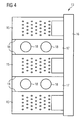
- FIGS 4 & 5 show views of a combined pick up head for picking up and transporting foils or thin strip in the thickness range of approximately 12 - 300 microns.
- the head assembly 13 consists of alternate sections of two types separated by partitions 14.
- One type of section 15 consists of a suction grid assembly as described above. Each suction grid section is supplied with air from a pressurised header 16 running the width of the head.
- the other sections 17 consist of two conventional sucker arrangements 18.
- the suckers 18 are connected to a vacuum pump means (not illustrated) as is well known in the art. When operating, the sucker assemblies can be lowered below the level of grids 4 via a linear motion means 19 such as a small pneumatic cylinder. When not operating, the suckers 18 can be raised above the level of the grids 4 by the same linear motion means 19.
- the number of each type of section and hence the width of the head is matched to the width of the foil and/or strip to be picked up.
- such a head would have 3 usual modes of operation, depending on the thickness of the foil or strip to be picked up.
- the suction grids 4 For thin foil in the range 12 to approximately 50 microns, only the suction grids 4 would be used, the suckers 18 would be retracted and their vacuum means turned off.
- the suckers 18 For thin strip in the range 100 to 300 microns, the suckers 18 would be extended and the vacuum pump means turned on. Good grip would then be achieved between the suckers 18 and the relatively stiff strip. Therefore the air supply to the suction grids 4 can be turned off in this case. Between 50 and 100 microns thick there is an intermediate case where it is advantageous to have the suckers 18 extended and both the suckers 18 and the grids 4 in operation simultaneously.
- Figure 6 shows an alternative design of pick up head where the suction grid and blowing action are separated.
- the foil is picked up and held in the position shown on the pick up head by the following system:
- a vacuum pump means (not illustrated) applies reduced pressure via header or pipe 20 to a sealed box 21.
- the bottom of the box consists of a suction grid 22.
- the vacuum pump means lowers the pressure on the upper side of the holes 23, initially causing air to be drawn in through the holes 23.
- a pressurised header 24 supplies compressed air to one or more flat jet nozzles 25.
- a high velocity jet of air passes out of the nozzle(s) 25 and travels over the top of the leading edge of the foil 27.
Landscapes
- Engineering & Computer Science (AREA)
- Mechanical Engineering (AREA)
- Physics & Mathematics (AREA)
- Fluid Mechanics (AREA)
- Sheets, Magazines, And Separation Thereof (AREA)
- Supporting Of Heads In Record-Carrier Devices (AREA)
- Moving Of Heads (AREA)
- Advancing Webs (AREA)
- Cleaning In General (AREA)
Abstract
Description
- The invention relates generally to industrial processes where thin sheet material needs to be transported without damage. The invention is especially applicable in the field of aluminium foil and thin strip rolling mills and describes a new device capable of picking up and transporting foil in the range approximately 12 - 50 microns thickness. The device can be combined with existing systems which pick up foil and strip of greater thickness to produce a new combination device which is able to pick up and transport foil and strip in the range approximately 12 - 300 microns. The new device is suitable for use as part of the mill foil feeding system which enables foil or thin strip to be brought from the coil to the mill roll bite automatically.
- The ingoing side of an aluminium foil rolling mill consist of an uncoiling machine, a piece of equipment known as the "entry bridle", and the mill stand itself which contains the "work rolls" which reduce the foil in thickness. In order to start rolling, the free end of the foil coil must be picked up and transported to the mill bite through the entry bridle equipment, a distance of approximately 3 metres.
- Aluminium foil of the lower thickness range (down to 12 micron thickness) is extremely fragile and has almost no inherent stiffness. Picking up such a material automatically, and transporting over and through equipment, without damaging it is therefore challenging. Traditionally this has been done manually with a typical procedure being as follows:
- Manually lift the foil end from the coil
- Fold the foil to create an arrowhead and fit over the end of a wooden pole
- Rotate the coil to allow slack foil
- Push the pole through the bridle until the foil is caught and pulled by the work roll nip
- A skilled operator can perform such a function, but the procedure involves the operator standing close to moving machinery and risks damage to the bridle or mill stand equipment if the pole is mis-handled. For personnel and equipment safety it is therefore desirable that the foil is lifted from the coil and carried to the mill bite automatically. Additionally, aluminium foil / strip of the higher thickness range (up to 300 micron thickness) is quite stiff which means that a different method has been required to feed up this material. Again a manual procedure has traditionally been followed which this time involves the operator supporting the front end of the strip underneath with the wooden pole whilst the strip is wound off the coil. The same safety and damage implications are present as for foil feeding. Therefore it is even more desirable to have one system which can automatically lift and carry foil or strip with a wide range of thicknesses.
- Several systems are in existence which attempt to carry out the foil feeding function, however, each has only met with limited success:
- Patent
GB2185927 - Patent application
JP56001216 - Patent
US4520645 describes a method and equipment for the automatic threading of a foil mill. A foil pick up head is described where vacuum suckers are used to grip the foil and air jets are used to lift the front end of the foil to facilitate threading into the mill bite. Two different mechanisms are described for carrying the foil pick up head from the coil to near the mill bite. - Patent
EP1518615 describes essentially the same method using vacuum suckers for picking up the foil from the coil and transporting it towards the mill, except in this case the foil is put down before the entry bridle and further transported using air floatation tables. - It has been found in practise that using vacuum suckers to lift foil and strip has certain limitations. The method can work well for thicker foil and strip above approximately 50 microns in thickness. In this case, on contact between the sucker and strip, whilst applying a suction action through the hole in the centre of the sucker, the flexible lip of the sucker (typically rubber-like material) deflects as low pressure is created between sucker and strip, whilst the stiffer aluminium strip stays rigid. Hence a good grip is created and the strip is not damaged. However, when attempting to lift thin foils of approximately 50 microns thickness and below, the foil has much less stiffness. Therefore when the sucker lip and foil is placed in contact, whilst applying a suction action through the hole in the centre of the sucker, the foil deflects instead of, or as well as the sucker lip. It is difficult to create an effective seal between 2 flexible objects and so poor grip will result between sucker and foil. If the suction action is increased within the central hole of the sucker, the higher pressure difference created may break a hole through thin foil or cause it to buckle and be partially pulled up inside the sucker hole itself.
- Therefore in order to pick up and transport thin foils it is necessary to devise an alternative head design and it is to this end that the new invention is presented hereto. It is considered that the mechanisms necessary for transportation of the pick up head from the coil to the mill bite are well established by prior art and are therefore not discussed beyond that which is necessary to understand the invention.
- According to the invention, apparatus for transporting sheet material comprises the features set out in
claim 1 attached hereto. - In one embodiment, the means for providing a pressure differential comprises a vacuum source and a nozzle arranged to extract air from a region above the plate. Preferably, the plate is arranged to form the base of the enclosure with the nozzle/vacuum source arranged to evacuate the enclosure.
- In an alternative embodiment, the pressure differential is achieved by directing a flow of gas over the upper surface of the plate. This is conveniently achieved using a source of pressurised gas and a nozzle arranged to direct the gas over the upper surface of the plate. Preferably, a flat jet compressed air nozzle is used. Moreover the effectiveness of the flowing gas is preferably improved by arranging the plate to form the base of a conduit which bounds the flow of gas.
- Preferably, the effect of the flowing gas is further enhanced where by incorporating at the holes, a streamlined hood having a tapered, closed end arranged towards the flowing gas (at the upstream side of the hole) and an open end arranged at the downstream side.
- Preferred embodiments of the invention further comprise means for directing a flow of gas from an edge of the plate in a direction substantially parallel to, and above, the plane of the plate. In some embodiments a continuous flow of gas is directed over the upper surface of the plate and in a direction substantially parallel to, and above, the plane of the plate after the gas passes over said upper surface.
- Preferably, the holes on the grid are staggered.
- In at least one embodiment, the apparatus includes a number of plates, each having an associated plurality of holes and associated means for providing a pressure differential between the upper surface and lower surface of the plate. Each plate may be attached to adjacent plates with the nozzles being in fluid communication.
- In some embodiments, the apparatus includes conventional suckers attached to a vacuum source for lifting sheet material. These may conveniently be arranged in sections which alternate with the plates of the invention. In a preferred embodiment, the suckers are moveable by, for example, a linear actuator so that they may be raised above or below the level of the plates.
- In a preferred embodiment, the invention is used for the transport of metal foil.
- According to a second aspect of the invention there is provided a method for transporting sheet material as recited in the independent method claim.
- In order to grip foil with a thickness of less than 50 microns without damaging it and therefore to overcome the main limitation of previous pick up head designs, the new invention has a "suction grid" consisting of numerous small holes in a stiff plate. This replaces the conventional rubber suckers as the mechanism by which the foil is gripped. Although the thin foil is flexible, the contrasting stiffness of the suction plate allows a good seal, and hence good grip to form between the foil and the head. Additionally, the small size of the suction holes prevents the foil from deflecting into the holes excessively which in tum prevents damage or holes forming through the foil.
- The suction pressure through the grid holes is provided by the passage of a stream of high speed air over the upper surface of the holes. The high speed air stream is provided by a flat slot type nozzle connected to a compressed air supply. The suction pressure occurs due to the so called "Bernoulli effect" where moving air on the upper surface of the holes is at lower pressure than the still air below the grid or foil. Although the effect can work with simple straight drilled holes, the suction effect can be enhanced by ensuring that the high speed air stream passes smoothly over the holes with no tendency to blow through them rather than produce suction. This can be done by using holes which have streamlined hoods over their leading edges (see
figure 3 ). A further benefit to smooth air flow and hence maintained air velocity is also achieved by arranging the holes in a staggered pattern. - Alternatively, the suction pressure could be provided by a vacuum pump means, but this would not allow the following additional advantage over patent
US4520645 to be realised. - The high velocity air flow used to create the suction effect loses little of its velocity over the grid. After leaving the grid the air flow can be directed over the front of the foil. As described in
US4520645 , again via the Bemoulli Effect, this gives a lifting action to the front end of the foil, allowing easy feeding of the foil into the mill bite without the pick up head touching the rolls. However, whereas inUS4520645 two separate actions of sucking and blowing are required to produce the foil gripping and the lifting of the foil front end, the new invention allows both actions to be performed by the same air stream with associated reductions in equipment complexity and cost. - The invention will now be described, by non-limiting example, with reference to
figures 1, 2 & 3 which show a preferred embodiment of the invention. -
Figure 1 shows a cross section of the pick up head gripping a piece of thin foil.Figure 2 shows a plan view of a pick up head for narrow foils, or one section of a pick up head for wider foils. The foil is picked up and held in the position shown on the pick up head by the following system: A pressurisedheader 1 supplies compressed air to one or moreflat jet nozzles 2. A high velocity jet of air (indicated by the large arrows) passes out of the nozzle(s) and travels along atunnel 6, created bytop cover 3,grid 4, andside plates 5. As the jet of air passes along thetunnel 6, it lowers the pressure on the upper side of theholes 7, initially causing air (indicated by the small arrows) to be drawn in through theholes 7. - When the suction head is placed in close proximity to a
foil strip 8, a suction force is produced between thefoil 8 and thegrid 4 due to the pressure differential between the air in thetunnel 6 and the air below the foil. Additionally, any foil which is protruding in front of thehead 9 is subject to a lifting force caused by the high velocity air travelling over its upper surface. - Thereby the front of a foil strip can be lifted and held by the pick up head with the foil taking up a shape similar to that shown in
figure 1 . -
Figure 3 shows a plan view and cross section through an optimised hole design. Thehole 10 has astreamlined hood 11 which serves to increase the suction pressure created through the hole and prevent too much velocity being lost by themain air stream 12 as it passes over thehole 10. -
Figures 4 &5 show views of a combined pick up head for picking up and transporting foils or thin strip in the thickness range of approximately 12 - 300 microns. Thehead assembly 13 consists of alternate sections of two types separated bypartitions 14. One type ofsection 15 consists of a suction grid assembly as described above. Each suction grid section is supplied with air from a pressurisedheader 16 running the width of the head. Theother sections 17 consist of twoconventional sucker arrangements 18. Thesuckers 18 are connected to a vacuum pump means (not illustrated) as is well known in the art. When operating, the sucker assemblies can be lowered below the level ofgrids 4 via a linear motion means 19 such as a small pneumatic cylinder. When not operating, thesuckers 18 can be raised above the level of thegrids 4 by the same linear motion means 19. - The number of each type of section and hence the width of the head is matched to the width of the foil and/or strip to be picked up.
- In use, such a head would have 3 usual modes of operation, depending on the thickness of the foil or strip to be picked up. For thin foil in the
range 12 to approximately 50 microns, only thesuction grids 4 would be used, thesuckers 18 would be retracted and their vacuum means turned off. For thin strip in the range 100 to 300 microns, thesuckers 18 would be extended and the vacuum pump means turned on. Good grip would then be achieved between thesuckers 18 and the relatively stiff strip. Therefore the air supply to thesuction grids 4 can be turned off in this case. Between 50 and 100 microns thick there is an intermediate case where it is advantageous to have thesuckers 18 extended and both thesuckers 18 and thegrids 4 in operation simultaneously. -
Figure 6 shows an alternative design of pick up head where the suction grid and blowing action are separated. The foil is picked up and held in the position shown on the pick up head by the following system: A vacuum pump means (not illustrated) applies reduced pressure via header orpipe 20 to a sealedbox 21. The bottom of the box consists of asuction grid 22. The vacuum pump means lowers the pressure on the upper side of theholes 23, initially causing air to be drawn in through theholes 23. A pressurisedheader 24 supplies compressed air to one or moreflat jet nozzles 25. A high velocity jet of air (indicated by the large arrow) passes out of the nozzle(s) 25 and travels over the top of the leading edge of thefoil 27. - When the suction head is placed in close proximity to a
foil strip 26, a suction force is produced between thefoil 26 and thegrid 22 due to the pressure differential between the air in thebox 21 and the air below the foil. Additionally, any foil which is protruding in front of thehead 27 is subject to a lifting force caused by the high velocity air travelling over its upper surface. - Thereby the front of a foil strip can be lifted and held by the pick up head with the foil taking up a shape similar to that shown in
figure 6 .
Claims (25)
- Apparatus for transporting sheet material (8; 26) comprising:a plate having a plurality of holes (7) arranged to form a grid (4; 22);means for providing a pressure differential between an upper surface and a lower surface of the plate andmeans for directing a flow of gas from an edge of the plate in a direction substantially parallel to, and above , the plane of the plate;motor means for transporting the plate.
- Apparatus according to claim 1, where the means for providing a pressure differential comprises a vacuum source and a nozzle (25) arranged to extract air from a region above the plate.
- Apparatus according to claim 2, where the plate forms the base of an enclosure, the vacuum source and nozzle being arranged to evacuate the enclosure.
- Apparatus according to claim 1, where the means for providing a pressure differential comprises means (2) for directing a flow of gas over the upper surface of the plate.
- Apparatus according to claim 4, wherein the means (2) for directing a flow of gas comprises a source (1) of pressurized gas and a nozzle (2) arranged to direct a flow of said gas across the upper surface.
- Apparatus according to claim 5, where the nozzle (2) comprises a flat jet compressed air nozzle.
- Apparatus according to any of claims 4 - 6 wherein the plate forms the base of a conduit (6), said conduit bounding the flow of gas over the plate.
- Apparatus according to any of claims 4 - 7, wherein the holes (10) each comprise a streamlined hood (11) located in the flowing gas and having a closed, tapered upstream end and an open downstream end.
- Apparatus according to any preceding claim, wherein the means for directing a flow of gas from an edge of the plate in a direction substantially parallel to, and above, the plane of the plate and the means for providing the pressure differential between the upper surface and a lower surface of the plate comprises the same flow of gas.
- Apparatus according to any preceding claim, wherein the holes (7) are arranged in a staggered pattern.
- Apparatus according to any preceding claim, comprising a plurality of plates, wherein each plate has an associated plurality of holes arranged to form a grid and each plate has associated means (16) for providing a pressure differential between an upper surface and a lower surface of the plate.
- Apparatus according to claim 11, wherein each plate is physically attached to adjacent plates and the associated means (16) for providing a pressure differential are in fluid communication.
- Apparatus according to claim 12, further comprising a plurality of suckers (18) and a vacuum source, the apparatus being operable to pick up sheet material by contacting the suckers (18) with the sheet material and application of vacuum to the suckers.
- Apparatus according to claim 13, comprising a plurality of sections wherein:a first type of section (15) comprises a plate having a plurality of holes arranged to form a grid and means for providing a pressure differential between an upper surface and a lower surface of the plate anda second type of section (17) comprises a plurality of suckers (18) connected to a vacuum source.
- Apparatus according to claim 14, further comprising a plurality of linear actuators (19) operable to adjust the height of the suckers (18) in relation to the plates.
- Apparatus according to any preceding claim, adapted for transporting metal foil.
- A method of transporting sheet material (8; 26) comprising the steps of:locating a plate, having a plurality of holes (7) arranged to form a grid, (4; 22) such that a lower surface of the plate is proximal to the sheet material;directing a flow of gas from an edge of the plate in a direction substantially parallel to, and above, the plane of the plate;inducing a reduced pressure in a region above the plate, relative to a region below the plate andtransporting the plate.
- A method according to claim 17, where a reduced pressure is induced in the region above the plate by applying a vacuum thereto.
- A method according to claim 18, comprising the steps of forming an enclosure (6) having one boundary defined by the plate and evacuating said enclosure.
- A method according to claim 17, where a reduced pressure is induced in the region above the plate by directing a flow of gas over the upper surface of the plate.
- A method according to claim 20, where the flow of gas is directed from a source (1) of pressurized gas using a nozzle (2).
- A method according to claim 21, where a flat jet compressed air nozzle (2) is used to direct the flow of gas.
- A method according to any of claims 17 - 22, comprising the steps of completing a conduit (6) having one boundary defined by the plate and directing the flow of gas through the conduit (6).
- A method of using the apparatus of any of claims 14 to 16 when dependent on claim 13 comprising the step of determining a thickness of the sheet material to be transported and in the event of the determined sheet thickness being in the range of 12 to 50 microns operating the apparatus in a first mode, in the event of the determined sheet thickness being in the range of 100 to 300 microns operating the apparatus in a second mode and in the event of determined thickness being in the range of 50 to 100 microns operating the apparatus in a third mode wherein, in the first mode, the suckers (18) do not have a vacuum applied to them and are retracted away from the sheet; in the second mode the suckers (18) are extended to a position proximal the sheet and a vacuum is applied to them to enable gripping of the sheet with the sucker sections having no vacuum applied, and, in the third mode, the suckers (18) are extended to a position proximal the sheet and a vacuum is applied both to the suckers and sucker sections to enable gripping of the sheet both by the suckers and the sucker sections.
- A method as claimed in any of claims 17 to 24 wherein the sheet material transported is wider strip material.
Applications Claiming Priority (1)
| Application Number | Priority Date | Filing Date | Title |
|---|---|---|---|
| GB0909873A GB2470913B (en) | 2009-06-09 | 2009-06-09 | Foil pick up head |
Publications (2)
| Publication Number | Publication Date |
|---|---|
| EP2260955A1 EP2260955A1 (en) | 2010-12-15 |
| EP2260955B1 true EP2260955B1 (en) | 2012-01-18 |
Family
ID=40937095
Family Applications (1)
| Application Number | Title | Priority Date | Filing Date |
|---|---|---|---|
| EP10164843A Not-in-force EP2260955B1 (en) | 2009-06-09 | 2010-06-03 | Apparatus for and method of transporting sheet material |
Country Status (6)
| Country | Link |
|---|---|
| EP (1) | EP2260955B1 (en) |
| CN (1) | CN101920274B (en) |
| AT (1) | ATE541653T1 (en) |
| BR (1) | BRPI1002128A8 (en) |
| ES (1) | ES2383284T3 (en) |
| GB (1) | GB2470913B (en) |
Families Citing this family (5)
| Publication number | Priority date | Publication date | Assignee | Title |
|---|---|---|---|---|
| CN104229531B (en) * | 2013-06-09 | 2017-10-24 | 征图新视(江苏)科技有限公司 | Grid air intake device |
| US10525763B2 (en) * | 2014-12-04 | 2020-01-07 | Gietz Ag | Flat foil printing press having foil web and sheet guidance |
| CN107539811A (en) * | 2016-06-29 | 2018-01-05 | 湖南工业大学 | A kind of paper feeder for sand big gun machine |
| CN111532031B (en) * | 2020-05-22 | 2021-09-21 | 南京六合高新建设发展有限公司 | Thermal printer |
| CN113401698B (en) * | 2021-06-18 | 2022-08-16 | 成都新图新材料股份有限公司 | Abandonment coiled material rolling machine |
Family Cites Families (15)
| Publication number | Priority date | Publication date | Assignee | Title |
|---|---|---|---|---|
| DE2534622A1 (en) * | 1975-08-02 | 1977-02-10 | Achenbach Buschhuetten Gmbh | FEDING METAL FOIL INTO A ROLLING MILl - using transporter with suction heads carrying front end of foil into roll gap |
| JPS561216A (en) * | 1979-06-15 | 1981-01-08 | Kobe Steel Ltd | Passing method for aluminum foil |
| US4520645A (en) | 1982-01-26 | 1985-06-04 | Davy Mckee (Poole) Limited | Feeding thin foil-like material into a gap between a pair of rotatable rolls |
| DD243015A1 (en) * | 1985-11-28 | 1987-02-18 | Halbleiterwerk Veb | TRANSPORTER |
| DE3600372A1 (en) | 1986-01-09 | 1987-07-16 | Achenbach Buschhuetten Gmbh | CONVEYOR DEVICE FOR IMPORTING TAPE MATERIAL IN TAPE MACHINING MACHINES |
| DE3637567A1 (en) * | 1986-11-04 | 1988-05-05 | Trumpf Gmbh & Co | Suction apparatus on or for a processing machine |
| JPH0561216A (en) * | 1990-11-28 | 1993-03-12 | Ricoh Co Ltd | Electrophotographic photoreceptor |
| JP3360889B2 (en) * | 1993-09-24 | 2003-01-07 | 石川島播磨重工業株式会社 | Side guide equipment for strip winder |
| JP3372009B2 (en) * | 1995-04-28 | 2003-01-27 | 花王株式会社 | Meat modifiers and edible meat or meat products treated therewith |
| JP3275997B2 (en) * | 1996-09-27 | 2002-04-22 | 川崎製鉄株式会社 | Winding equipment for continuous hot rolling and winding method using the same |
| DE10305414B3 (en) * | 2003-02-06 | 2004-09-16 | Sms Demag Ag | Device for transferring or threading tape starts |
| DE20314840U1 (en) | 2003-09-25 | 2003-11-20 | Achenbach Buschhütten GmbH, 57223 Kreuztal | Device for inserting strip material and trimming the strip edges for strip processing machines, in particular fine strip and film rolling mills |
| CN2892771Y (en) * | 2005-12-29 | 2007-04-25 | 袁建中 | Exhaust suction disc |
| JP2009000804A (en) * | 2007-05-22 | 2009-01-08 | Nidec-Read Corp | Absorption table |
| CN201423544Y (en) * | 2009-05-07 | 2010-03-17 | 杭州正驰达精密机械有限公司 | Vacuum absorption clamp for clamping thin sheet part |
-
2009
- 2009-06-09 GB GB0909873A patent/GB2470913B/en not_active Expired - Fee Related
-
2010
- 2010-06-03 EP EP10164843A patent/EP2260955B1/en not_active Not-in-force
- 2010-06-03 ES ES10164843T patent/ES2383284T3/en active Active
- 2010-06-03 AT AT10164843T patent/ATE541653T1/en active
- 2010-06-08 CN CN201010198708.4A patent/CN101920274B/en not_active Expired - Fee Related
- 2010-06-08 BR BRPI1002128A patent/BRPI1002128A8/en not_active IP Right Cessation
Also Published As
| Publication number | Publication date |
|---|---|
| ATE541653T1 (en) | 2012-02-15 |
| GB0909873D0 (en) | 2009-07-22 |
| CN101920274B (en) | 2015-12-02 |
| ES2383284T3 (en) | 2012-06-20 |
| BRPI1002128A2 (en) | 2011-07-05 |
| CN101920274A (en) | 2010-12-22 |
| GB2470913A (en) | 2010-12-15 |
| EP2260955A1 (en) | 2010-12-15 |
| BRPI1002128A8 (en) | 2015-11-10 |
| GB2470913B (en) | 2011-05-25 |
Similar Documents
| Publication | Publication Date | Title |
|---|---|---|
| EP2260955A1 (en) | Apparatus for and method of transporting sheet material | |
| KR101563443B1 (en) | Hot-stamping printing device | |
| CA1176556A (en) | Means in a paper machine for cutting and guiding the marginal strip of the paper web | |
| US5386751A (en) | Method and apparatus for forming and gripping a web beginning of a replacement roll | |
| JP5090614B2 (en) | Machine for processing sheets, in particular a method and apparatus for guiding sheets to a printing press | |
| US4997524A (en) | Method and apparatus for transport of a web to be threaded | |
| GB2114101A (en) | Guiding leading web end to roller nip | |
| JP5010066B2 (en) | Printing machine guide apparatus for processing sheets and sheet processing machine equipped with the guide apparatus | |
| US5635030A (en) | Process and device for guiding a material web | |
| KR20050082141A (en) | The equipment for seperating double side film on the glass | |
| US6131784A (en) | Threading device | |
| US20110233848A1 (en) | Sheet containing device | |
| US20030159789A1 (en) | Method and device in leading a web threading tail particularly in a paper machine | |
| JP2993265B2 (en) | Air blow type Pyra | |
| EP3774361B1 (en) | Media transfer | |
| KR100967715B1 (en) | Strip Sheet Attachment Removal Device | |
| JP2004315232A (en) | Method and device for guiding paper sheet to paper sheet processing machine | |
| KR100761719B1 (en) | Scratch-resistant device for stripping out the top part of the strip | |
| EP1370398B1 (en) | Method and apparatus for trimming sheet metal | |
| JPH0537961Y2 (en) | ||
| JPH033748A (en) | Removing device for upper plate for working printed board | |
| SU906869A1 (en) | Apparatus for stacking metallic sheets | |
| KR20060085553A (en) | Peeling device for glass double-sided film | |
| JP2518450Y2 (en) | Paper web transfer guide device | |
| JPH0741719Y2 (en) | Disposal device for laminated metal plates |
Legal Events
| Date | Code | Title | Description |
|---|---|---|---|
| PUAI | Public reference made under article 153(3) epc to a published international application that has entered the european phase |
Free format text: ORIGINAL CODE: 0009012 |
|
| AK | Designated contracting states |
Kind code of ref document: A1 Designated state(s): AL AT BE BG CH CY CZ DE DK EE ES FI FR GB GR HR HU IE IS IT LI LT LU LV MC MK MT NL NO PL PT RO SE SI SK SM TR |
|
| AX | Request for extension of the european patent |
Extension state: BA ME RS |
|
| 17P | Request for examination filed |
Effective date: 20110520 |
|
| RIC1 | Information provided on ipc code assigned before grant |
Ipc: B21C 47/34 20060101AFI20110621BHEP Ipc: B21B 39/02 20060101ALI20110621BHEP Ipc: B65H 20/10 20060101ALI20110621BHEP Ipc: B21D 43/18 20060101ALI20110621BHEP |
|
| GRAP | Despatch of communication of intention to grant a patent |
Free format text: ORIGINAL CODE: EPIDOSNIGR1 |
|
| GRAS | Grant fee paid |
Free format text: ORIGINAL CODE: EPIDOSNIGR3 |
|
| GRAA | (expected) grant |
Free format text: ORIGINAL CODE: 0009210 |
|
| AK | Designated contracting states |
Kind code of ref document: B1 Designated state(s): AL AT BE BG CH CY CZ DE DK EE ES FI FR GB GR HR HU IE IS IT LI LT LU LV MC MK MT NL NO PL PT RO SE SI SK SM TR |
|
| REG | Reference to a national code |
Ref country code: GB Ref legal event code: FG4D |
|
| REG | Reference to a national code |
Ref country code: CH Ref legal event code: EP |
|
| REG | Reference to a national code |
Ref country code: AT Ref legal event code: REF Ref document number: 541653 Country of ref document: AT Kind code of ref document: T Effective date: 20120215 Ref country code: IE Ref legal event code: FG4D |
|
| REG | Reference to a national code |
Ref country code: DE Ref legal event code: R096 Ref document number: 602010000686 Country of ref document: DE Effective date: 20120322 |
|
| REG | Reference to a national code |
Ref country code: NL Ref legal event code: VDEP Effective date: 20120118 |
|
| REG | Reference to a national code |
Ref country code: ES Ref legal event code: FG2A Ref document number: 2383284 Country of ref document: ES Kind code of ref document: T3 Effective date: 20120620 |
|
| LTIE | Lt: invalidation of european patent or patent extension |
Effective date: 20120118 |
|
| PG25 | Lapsed in a contracting state [announced via postgrant information from national office to epo] |
Ref country code: BG Free format text: LAPSE BECAUSE OF FAILURE TO SUBMIT A TRANSLATION OF THE DESCRIPTION OR TO PAY THE FEE WITHIN THE PRESCRIBED TIME-LIMIT Effective date: 20120418 Ref country code: LT Free format text: LAPSE BECAUSE OF FAILURE TO SUBMIT A TRANSLATION OF THE DESCRIPTION OR TO PAY THE FEE WITHIN THE PRESCRIBED TIME-LIMIT Effective date: 20120118 Ref country code: NO Free format text: LAPSE BECAUSE OF FAILURE TO SUBMIT A TRANSLATION OF THE DESCRIPTION OR TO PAY THE FEE WITHIN THE PRESCRIBED TIME-LIMIT Effective date: 20120418 Ref country code: NL Free format text: LAPSE BECAUSE OF FAILURE TO SUBMIT A TRANSLATION OF THE DESCRIPTION OR TO PAY THE FEE WITHIN THE PRESCRIBED TIME-LIMIT Effective date: 20120118 Ref country code: IS Free format text: LAPSE BECAUSE OF FAILURE TO SUBMIT A TRANSLATION OF THE DESCRIPTION OR TO PAY THE FEE WITHIN THE PRESCRIBED TIME-LIMIT Effective date: 20120518 Ref country code: HR Free format text: LAPSE BECAUSE OF FAILURE TO SUBMIT A TRANSLATION OF THE DESCRIPTION OR TO PAY THE FEE WITHIN THE PRESCRIBED TIME-LIMIT Effective date: 20120118 Ref country code: BE Free format text: LAPSE BECAUSE OF FAILURE TO SUBMIT A TRANSLATION OF THE DESCRIPTION OR TO PAY THE FEE WITHIN THE PRESCRIBED TIME-LIMIT Effective date: 20120118 |
|
| PG25 | Lapsed in a contracting state [announced via postgrant information from national office to epo] |
Ref country code: PT Free format text: LAPSE BECAUSE OF FAILURE TO SUBMIT A TRANSLATION OF THE DESCRIPTION OR TO PAY THE FEE WITHIN THE PRESCRIBED TIME-LIMIT Effective date: 20120518 Ref country code: GR Free format text: LAPSE BECAUSE OF FAILURE TO SUBMIT A TRANSLATION OF THE DESCRIPTION OR TO PAY THE FEE WITHIN THE PRESCRIBED TIME-LIMIT Effective date: 20120419 Ref country code: FI Free format text: LAPSE BECAUSE OF FAILURE TO SUBMIT A TRANSLATION OF THE DESCRIPTION OR TO PAY THE FEE WITHIN THE PRESCRIBED TIME-LIMIT Effective date: 20120118 Ref country code: PL Free format text: LAPSE BECAUSE OF FAILURE TO SUBMIT A TRANSLATION OF THE DESCRIPTION OR TO PAY THE FEE WITHIN THE PRESCRIBED TIME-LIMIT Effective date: 20120118 Ref country code: LV Free format text: LAPSE BECAUSE OF FAILURE TO SUBMIT A TRANSLATION OF THE DESCRIPTION OR TO PAY THE FEE WITHIN THE PRESCRIBED TIME-LIMIT Effective date: 20120118 |
|
| PG25 | Lapsed in a contracting state [announced via postgrant information from national office to epo] |
Ref country code: CY Free format text: LAPSE BECAUSE OF FAILURE TO SUBMIT A TRANSLATION OF THE DESCRIPTION OR TO PAY THE FEE WITHIN THE PRESCRIBED TIME-LIMIT Effective date: 20120118 |
|
| PG25 | Lapsed in a contracting state [announced via postgrant information from national office to epo] |
Ref country code: CZ Free format text: LAPSE BECAUSE OF FAILURE TO SUBMIT A TRANSLATION OF THE DESCRIPTION OR TO PAY THE FEE WITHIN THE PRESCRIBED TIME-LIMIT Effective date: 20120118 Ref country code: SE Free format text: LAPSE BECAUSE OF FAILURE TO SUBMIT A TRANSLATION OF THE DESCRIPTION OR TO PAY THE FEE WITHIN THE PRESCRIBED TIME-LIMIT Effective date: 20120118 Ref country code: EE Free format text: LAPSE BECAUSE OF FAILURE TO SUBMIT A TRANSLATION OF THE DESCRIPTION OR TO PAY THE FEE WITHIN THE PRESCRIBED TIME-LIMIT Effective date: 20120118 Ref country code: SI Free format text: LAPSE BECAUSE OF FAILURE TO SUBMIT A TRANSLATION OF THE DESCRIPTION OR TO PAY THE FEE WITHIN THE PRESCRIBED TIME-LIMIT Effective date: 20120118 Ref country code: RO Free format text: LAPSE BECAUSE OF FAILURE TO SUBMIT A TRANSLATION OF THE DESCRIPTION OR TO PAY THE FEE WITHIN THE PRESCRIBED TIME-LIMIT Effective date: 20120118 Ref country code: DK Free format text: LAPSE BECAUSE OF FAILURE TO SUBMIT A TRANSLATION OF THE DESCRIPTION OR TO PAY THE FEE WITHIN THE PRESCRIBED TIME-LIMIT Effective date: 20120118 |
|
| PLBE | No opposition filed within time limit |
Free format text: ORIGINAL CODE: 0009261 |
|
| STAA | Information on the status of an ep patent application or granted ep patent |
Free format text: STATUS: NO OPPOSITION FILED WITHIN TIME LIMIT |
|
| PG25 | Lapsed in a contracting state [announced via postgrant information from national office to epo] |
Ref country code: SK Free format text: LAPSE BECAUSE OF FAILURE TO SUBMIT A TRANSLATION OF THE DESCRIPTION OR TO PAY THE FEE WITHIN THE PRESCRIBED TIME-LIMIT Effective date: 20120118 |
|
| 26N | No opposition filed |
Effective date: 20121019 |
|
| PG25 | Lapsed in a contracting state [announced via postgrant information from national office to epo] |
Ref country code: MC Free format text: LAPSE BECAUSE OF NON-PAYMENT OF DUE FEES Effective date: 20120630 |
|
| REG | Reference to a national code |
Ref country code: DE Ref legal event code: R097 Ref document number: 602010000686 Country of ref document: DE Effective date: 20121019 |
|
| PG25 | Lapsed in a contracting state [announced via postgrant information from national office to epo] |
Ref country code: MK Free format text: LAPSE BECAUSE OF FAILURE TO SUBMIT A TRANSLATION OF THE DESCRIPTION OR TO PAY THE FEE WITHIN THE PRESCRIBED TIME-LIMIT Effective date: 20120118 |
|
| REG | Reference to a national code |
Ref country code: IE Ref legal event code: MM4A |
|
| PG25 | Lapsed in a contracting state [announced via postgrant information from national office to epo] |
Ref country code: IE Free format text: LAPSE BECAUSE OF NON-PAYMENT OF DUE FEES Effective date: 20120603 |
|
| REG | Reference to a national code |
Ref country code: ES Ref legal event code: PC2A Owner name: SIEMENS PLC. Effective date: 20130702 |
|
| REG | Reference to a national code |
Ref country code: GB Ref legal event code: 732E Free format text: REGISTERED BETWEEN 20130627 AND 20130703 |
|
| PG25 | Lapsed in a contracting state [announced via postgrant information from national office to epo] |
Ref country code: MT Free format text: LAPSE BECAUSE OF FAILURE TO SUBMIT A TRANSLATION OF THE DESCRIPTION OR TO PAY THE FEE WITHIN THE PRESCRIBED TIME-LIMIT Effective date: 20120118 |
|
| REG | Reference to a national code |
Ref country code: FR Ref legal event code: TP Owner name: SIEMENS PLC, GB Effective date: 20130709 |
|
| REG | Reference to a national code |
Ref country code: DE Ref legal event code: R082 Ref document number: 602010000686 Country of ref document: DE Representative=s name: MAIER, DANIEL OLIVER, DIPL.-ING. UNIV., DE |
|
| REG | Reference to a national code |
Ref country code: DE Ref legal event code: R081 Ref document number: 602010000686 Country of ref document: DE Owner name: SIEMENS PLC., GB Free format text: FORMER OWNER: SIEMENS VAI METALS TECHNOLOGIES LTD., SHEFFIELD, GB Effective date: 20130925 Ref country code: DE Ref legal event code: R082 Ref document number: 602010000686 Country of ref document: DE Representative=s name: MAIER, DANIEL OLIVER, DIPL.-ING. UNIV., DE Effective date: 20130925 Ref country code: DE Ref legal event code: R081 Ref document number: 602010000686 Country of ref document: DE Owner name: SIEMENS PLC., FRIMLEY, GB Free format text: FORMER OWNER: SIEMENS VAI METALS TECHNOLOGIES LTD., SHEFFIELD, YORKSHIRE, GB Effective date: 20130925 Ref country code: DE Ref legal event code: R082 Ref document number: 602010000686 Country of ref document: DE Representative=s name: KINNSTAETTER, KLAUS, DIPL.-PHYS.UNIV., DE Effective date: 20130925 Ref country code: DE Ref legal event code: R081 Ref document number: 602010000686 Country of ref document: DE Owner name: PRIMETALS TECHNOLOGIES, LTD., GB Free format text: FORMER OWNER: SIEMENS VAI METALS TECHNOLOGIES LTD., SHEFFIELD, YORKSHIRE, GB Effective date: 20130925 |
|
| PG25 | Lapsed in a contracting state [announced via postgrant information from national office to epo] |
Ref country code: AL Free format text: LAPSE BECAUSE OF FAILURE TO SUBMIT A TRANSLATION OF THE DESCRIPTION OR TO PAY THE FEE WITHIN THE PRESCRIBED TIME-LIMIT Effective date: 20120118 |
|
| PG25 | Lapsed in a contracting state [announced via postgrant information from national office to epo] |
Ref country code: TR Free format text: LAPSE BECAUSE OF FAILURE TO SUBMIT A TRANSLATION OF THE DESCRIPTION OR TO PAY THE FEE WITHIN THE PRESCRIBED TIME-LIMIT Effective date: 20120118 |
|
| PG25 | Lapsed in a contracting state [announced via postgrant information from national office to epo] |
Ref country code: SM Free format text: LAPSE BECAUSE OF FAILURE TO SUBMIT A TRANSLATION OF THE DESCRIPTION OR TO PAY THE FEE WITHIN THE PRESCRIBED TIME-LIMIT Effective date: 20120118 |
|
| PG25 | Lapsed in a contracting state [announced via postgrant information from national office to epo] |
Ref country code: HU Free format text: LAPSE BECAUSE OF FAILURE TO SUBMIT A TRANSLATION OF THE DESCRIPTION OR TO PAY THE FEE WITHIN THE PRESCRIBED TIME-LIMIT Effective date: 20100603 |
|
| REG | Reference to a national code |
Ref country code: CH Ref legal event code: PL |
|
| PG25 | Lapsed in a contracting state [announced via postgrant information from national office to epo] |
Ref country code: CH Free format text: LAPSE BECAUSE OF NON-PAYMENT OF DUE FEES Effective date: 20140630 Ref country code: LI Free format text: LAPSE BECAUSE OF NON-PAYMENT OF DUE FEES Effective date: 20140630 |
|
| REG | Reference to a national code |
Ref country code: AT Ref legal event code: PC Ref document number: 541653 Country of ref document: AT Kind code of ref document: T Owner name: SIEMENS PLC, GB Effective date: 20150417 |
|
| REG | Reference to a national code |
Ref country code: GB Ref legal event code: 732E Free format text: REGISTERED BETWEEN 20150521 AND 20150527 |
|
| REG | Reference to a national code |
Ref country code: FR Ref legal event code: PLFP Year of fee payment: 7 |
|
| PGFP | Annual fee paid to national office [announced via postgrant information from national office to epo] |
Ref country code: LU Payment date: 20160622 Year of fee payment: 7 |
|
| REG | Reference to a national code |
Ref country code: DE Ref legal event code: R082 Ref document number: 602010000686 Country of ref document: DE Representative=s name: KINNSTAETTER, KLAUS, DIPL.-PHYS.UNIV., DE |
|
| REG | Reference to a national code |
Ref country code: DE Ref legal event code: R082 Ref document number: 602010000686 Country of ref document: DE Representative=s name: KINNSTAETTER, KLAUS, DIPL.-PHYS.UNIV., DE Ref country code: DE Ref legal event code: R081 Ref document number: 602010000686 Country of ref document: DE Owner name: PRIMETALS TECHNOLOGIES, LTD., GB Free format text: FORMER OWNER: SIEMENS PLC., FRIMLEY, CAMBERLY, GB |
|
| REG | Reference to a national code |
Ref country code: ES Ref legal event code: PC2A Owner name: PRIMETALS TECHNOLOGIES, LIMITED Effective date: 20170210 |
|
| REG | Reference to a national code |
Ref country code: LU Ref legal event code: PD Owner name: PRIMETALS TECHNOLOGIES, LIMITED; GB Free format text: FORMER OWNER: SIEMENS PLC Effective date: 20170201 |
|
| REG | Reference to a national code |
Ref country code: FR Ref legal event code: PLFP Year of fee payment: 8 |
|
| PGFP | Annual fee paid to national office [announced via postgrant information from national office to epo] |
Ref country code: DE Payment date: 20170621 Year of fee payment: 8 Ref country code: FR Payment date: 20170621 Year of fee payment: 8 Ref country code: GB Payment date: 20170620 Year of fee payment: 8 |
|
| REG | Reference to a national code |
Ref country code: FR Ref legal event code: TP Owner name: PRIMETALS TECHNOLOGIES, LIMITED, GB Effective date: 20170630 |
|
| PGFP | Annual fee paid to national office [announced via postgrant information from national office to epo] |
Ref country code: IT Payment date: 20170622 Year of fee payment: 8 Ref country code: AT Payment date: 20170622 Year of fee payment: 8 |
|
| PGFP | Annual fee paid to national office [announced via postgrant information from national office to epo] |
Ref country code: ES Payment date: 20170724 Year of fee payment: 8 |
|
| REG | Reference to a national code |
Ref country code: AT Ref legal event code: PC Ref document number: 541653 Country of ref document: AT Kind code of ref document: T Owner name: PRIMETALS TECHNOLOGIES, LIMITED, GB Effective date: 20171207 |
|
| PG25 | Lapsed in a contracting state [announced via postgrant information from national office to epo] |
Ref country code: LU Free format text: LAPSE BECAUSE OF NON-PAYMENT OF DUE FEES Effective date: 20170603 |
|
| REG | Reference to a national code |
Ref country code: DE Ref legal event code: R119 Ref document number: 602010000686 Country of ref document: DE |
|
| REG | Reference to a national code |
Ref country code: AT Ref legal event code: MM01 Ref document number: 541653 Country of ref document: AT Kind code of ref document: T Effective date: 20180603 |
|
| GBPC | Gb: european patent ceased through non-payment of renewal fee |
Effective date: 20180603 |
|
| PG25 | Lapsed in a contracting state [announced via postgrant information from national office to epo] |
Ref country code: IT Free format text: LAPSE BECAUSE OF NON-PAYMENT OF DUE FEES Effective date: 20180603 Ref country code: DE Free format text: LAPSE BECAUSE OF NON-PAYMENT OF DUE FEES Effective date: 20190101 Ref country code: AT Free format text: LAPSE BECAUSE OF NON-PAYMENT OF DUE FEES Effective date: 20180603 Ref country code: FR Free format text: LAPSE BECAUSE OF NON-PAYMENT OF DUE FEES Effective date: 20180630 Ref country code: GB Free format text: LAPSE BECAUSE OF NON-PAYMENT OF DUE FEES Effective date: 20180603 |
|
| REG | Reference to a national code |
Ref country code: ES Ref legal event code: FD2A Effective date: 20190916 |
|
| PG25 | Lapsed in a contracting state [announced via postgrant information from national office to epo] |
Ref country code: ES Free format text: LAPSE BECAUSE OF NON-PAYMENT OF DUE FEES Effective date: 20180604 |