JP5010066B2 - Printing machine guide apparatus for processing sheets and sheet processing machine equipped with the guide apparatus - Google Patents
Printing machine guide apparatus for processing sheets and sheet processing machine equipped with the guide apparatus Download PDFInfo
- Publication number
- JP5010066B2 JP5010066B2 JP2000380126A JP2000380126A JP5010066B2 JP 5010066 B2 JP5010066 B2 JP 5010066B2 JP 2000380126 A JP2000380126 A JP 2000380126A JP 2000380126 A JP2000380126 A JP 2000380126A JP 5010066 B2 JP5010066 B2 JP 5010066B2
- Authority
- JP
- Japan
- Prior art keywords
- sheet
- nozzle
- guide
- guide surface
- machine
- Prior art date
- Legal status (The legal status is an assumption and is not a legal conclusion. Google has not performed a legal analysis and makes no representation as to the accuracy of the status listed.)
- Expired - Fee Related
Links
Images

Classifications
-
- B—PERFORMING OPERATIONS; TRANSPORTING
- B65—CONVEYING; PACKING; STORING; HANDLING THIN OR FILAMENTARY MATERIAL
- B65H—HANDLING THIN OR FILAMENTARY MATERIAL, e.g. SHEETS, WEBS, CABLES
- B65H29/00—Delivering or advancing articles from machines; Advancing articles to or into piles
- B65H29/52—Stationary guides or smoothers
-
- B—PERFORMING OPERATIONS; TRANSPORTING
- B41—PRINTING; LINING MACHINES; TYPEWRITERS; STAMPS
- B41F—PRINTING MACHINES OR PRESSES
- B41F21/00—Devices for conveying sheets through printing apparatus or machines
-
- B—PERFORMING OPERATIONS; TRANSPORTING
- B65—CONVEYING; PACKING; STORING; HANDLING THIN OR FILAMENTARY MATERIAL
- B65H—HANDLING THIN OR FILAMENTARY MATERIAL, e.g. SHEETS, WEBS, CABLES
- B65H2406/00—Means using fluid
- B65H2406/10—Means using fluid made only for exhausting gaseous medium
- B65H2406/11—Means using fluid made only for exhausting gaseous medium producing fluidised bed
- B65H2406/113—Details of the part distributing the air cushion
Landscapes
- Engineering & Computer Science (AREA)
- Mechanical Engineering (AREA)
- Feeding Of Articles By Means Other Than Belts Or Rollers (AREA)
- Supply, Installation And Extraction Of Printed Sheets Or Plates (AREA)
- Delivering By Means Of Belts And Rollers (AREA)
- Discharge By Other Means (AREA)
Description
【0001】
【発明の属する技術分野】
本発明は、枚葉紙を載せて案内する案内面であって、該案内面上で、枚葉紙が機械の動作時にそれぞれ走行方向に先行する枚葉紙の縁部を強制案内されて引かれていく案内面と、案内面に開口し、案内面と各々の枚葉紙との間に、機械の動作時に空気クッションを形成するために気流を流通させるノズルとを有する、平坦状の被印刷材料を処理する機械、特に枚葉紙処理印刷機の案内装置にに関し、また、この種の案内装置を備えた平坦状の被印刷材料の処理機械に関する。
【0002】
【従来の技術】
前述のような種類の案内装置は、例えばDE4209067C2によって知られている。この公報は、空気クッション上でこの空気クッションと案内面との間を引かれていく枚葉紙が、危険領域で不十分な浮遊高さを占めるという問題を扱っている。この危険領域としては、枚葉紙の走行方向に関し枚葉紙の側方の縁部が挙げられる。
【0003】
前述の刊行物では、枚葉紙の側方向縁部の領域において十分な浮遊高さを保証するために、第1の実施形態によると、枚葉紙側縁に沿って案内面上に制動棒を配置することが提案されている。第2の実施形態では、各々の枚葉紙の外側の縁部を外側から下側に吹き付ける側部の送風装置が設けられている。これらの実施形態によって、空気のよどみが枚葉紙の枚葉紙の下側で生じ、そのよどみが浮遊高さを高める。
【0004】
上記の両方の場合においては、処理される被印刷材料の判寸法に適合させるための調節過程が必要である。
【0005】
【発明が解決しようとする課題】
本発明の目的は、上述の(「発明の属する技術分野」に記載されている)案内装置を、様々な判寸法の平坦状の被印刷材料を案内面上で案内するために、各々の判寸法に合わせるために調節しなければならない補助手段が不要であるように構成することにある。
【0006】
【課題を解決するための手段】
この目的を達成するために、本発明の案内装置においては、案内面に沿う被印刷材料の経路上で、異なる判の処理可能な被印刷材料の1つの、走行方向に関して側方向の各縁部に、案内面上で、閉じた表面を有する領域が相対している。
【0007】
この解決策は、次の知見から出発している。すなわち、案内面内に開口し、案内面とこの案内面上を引かれていく枚葉紙との間に空気クッションを形成するために気流を流通するノズルの開口領域には負圧が形成され、そして、枚葉紙を浮遊状態で案内するために必要な正圧が、それぞれの開口領域からいくらか離れた個所ではじめて形成される、という知見から出発している。本発明による解決策によって、様々な判寸法を有する処理可能な任意の被印刷材料の、走行方向に関して側方向の縁部が、ノズルの開口領域における負圧の作用領域に入ることが防止される。
【0008】
このことを実現するために、これらのノズルを次のように位置決めすることが十分に可能である。すなわち、最大判寸法よりも小さい可能な判寸法を処理する場合に、これらのノズルの一部を、このより小さい判寸法の側縁部の内側に配置する。
【0009】
望ましい実施形態においては、ノズルは、機械の動作時に機械の動作仕様に適合して気流を流通させる際に被印刷材料の側方向の縁部に方向合わせされる気流を生成し、また、ノズルは、走行方向(方向矢印24)に対して横方向に広がりをもつ領域に限定され、該広がりは、処理可能な最大の判寸法の被印刷材料よりも小さい判寸法の被印刷材料が有する、前記走行方向に対して横方向に延びる幅の範囲内にある。
【0010】
他の好適な実施形態では、ノズルが、機械の動作仕様に適った気流の流通を行う際に、前記側方の縁部に垂直に方向合わせされる気流を生成する。
【0011】
好適な他の構成では、ノズルが、前記処理に適合した最小の可能な寸法を有する被印刷材料の、前記走行方向に対して横方向に延びる幅の範囲内にある。
【0012】
これらの実施態様は、この目的の解決策を超える、一部は製造技術的な、また一部は機能的な利点を併せ持っている。
【0013】
これらのノズルを最小の判寸法の範囲内に配置された2つのノズル列だけに限定するという好ましい実施態様は、ノズルに送風を供給するために、案内面の広い領域にわたって分布された従来のノズルに供給する場合に比べ、少ない構成費用しか必要としない。ノズルをこのように整列することによって、特に、好ましい実施形態としてノズル列中においてノズルを互いに狭く隣接させる場合には、さらに、これによって走行方向にほとんど一定の圧力の推移が各々の枚葉紙の下側で生じるという点において機能的な利点が得られる。その結果、各々の枚葉紙の下側で発生する圧力プロファイルは、走行方向に対して横方向に、それ自体で望ましい効果を生み出し、しかも、各々の枚葉紙が走行方向に補強されるという効果を生じる。これは、案内面に沿う枚葉紙の走行を安定させる効果がある。
【0014】
【発明の実施の形態】
以下、本発明を、添付の図面に基づき、平坦状の被印刷材料処理機械の排紙装置における案内装置の例にしたがって詳細に説明する。
【0015】
以下、枚葉紙処理輪転印刷機の形態を平坦状の被印刷材料処理機械に基づいて説明する。
【0016】
ここでは、図1に概略的に示すように、排紙装置1が最後の処理ステーションの後段に配置されている。このような処理ステーションは、印刷ユニット、または、例えばニス引きユニットのような後処理ユニットであることができる。本実施例は、この最後の処理ステーションとして、オフセット処理で働く、圧胴2.1を有する印刷ユニット2を対象としている。圧胴2.1は、回転方向矢印5によって示されている処理方向に、圧胴2.1と、この圧胴2.1と協働するゴムブランケット胴2.2との間の印刷用ギャップを通過して各枚葉紙3を案内し、そして続いて、圧胴2.1に配置されていて枚葉紙3を枚葉紙3の先行端のくわえ縁部で捕捉するために設けられたくわえづめを開いた状態で、この枚葉紙3をチェーン搬送装置4に渡す。チェーン搬送装置4は、2つの搬送チェーン6を備え、それらの搬送チェーン6のそれぞれ1つが排紙装置1の各側壁に沿って適切に駆動するように周回するいる。各搬送チェーン6は、回転軸が互いに一列に並び同期して駆動される2つの駆動スプロケットホイール7のそれぞれ1つに巻き付けられており、また、本実施例では、駆動スプロケットホイール7に向かい合って処理方向に関して下流側にあるそれぞれの方向転換スプロケットホイール8を通って案内される。これら2つの搬送チェーン6の間には、これらの搬送チェーン6によって支持されていてくわえづめ9.1を有するくわえづめ装置9が延びており、このくわえづめ9.1は、圧胴2.1に配置されたくわえづめの間の間隙を通り抜け、そしてその際に枚葉紙3の先行端の前記くわえ縁部を捕捉した状態で、圧胴2.1に配置されたくわえづめが開く直前に各枚葉紙3を受け取り、そして枚葉紙3を案内装置10を通って枚葉紙制動装置11に搬送し、そしてこの場所で枚葉紙3を枚葉紙制動装置11に渡すために開く。枚葉紙制動装置11は、処理速度に比較して減速された堆積速度を枚葉紙3に伝え、そして、この堆積速度になった後に制動装置側で枚葉紙3を解放し、その結果、既に減速された各枚葉紙3は最終的に前縁ストッパ12に当たり、そして、この前縁ストッパ12とこの前縁ストッパ12に向かい合っている後縁ストッパ13とで揃えられた状態で、先行および後続の、または、先行または後続の枚葉紙3と共に、パイル14を構成し、該パイルは、このパイル14が積み重ねられた分だけ昇降ユニットによって降下することができる。この昇降ユニットについては、図1では、パイル14を支持する紙載せ台15と、この紙載せ台15を支持する、一点鎖線で表された昇降チェーン16とだけが図示されている。
【0017】
搬送チェーン6は、一方では駆動スプロケットホイール7と他方では方向転換スプロケットホイール8との間の経路に沿ってチェーン案内レールによって案内され、したがって、該チェーン案内レールは、車間チェーン伝動部(Kettentrume、スプロケットホイール間チェーン部分)のチェーン走行路を決定する。本例では、枚葉紙3は図1中における下側の車間チェーン伝動部によって搬送される。この下側の車間チェーン伝動部が走行する、チェーン走行路の部分には、このチェーン走行路の部分に向けられていて案内装置10上に形成された案内面17が続いている。案内面17とこの案内面17上をそれぞれ案内されていく枚葉紙3との間には、機械の動作時に、支持用空気クッションが形成される。このために、案内面17に通じる吹き付け空気ノズルを有する案内装置10が設けられている。この案内装置10については、図1ではその全体を表示するとともに接続管18の形態で概略だけを図示している。
【0018】
パイル14において印刷された枚葉紙3が互いに粘着することを防止するために、駆動スプロケットホイール7から枚葉紙制動装置11にかけて枚葉紙3の経路上に乾燥機19と粉かけ装置20が設けられている。
【0019】
乾燥機19による案内面17の過熱を防ぐために、枚葉紙案内装置10内には、冷却剤循環装置が組み込まれ、該冷却剤循環装置は、図1中には概略的に、案内面17に付属する冷却剤容器23に設けられた入口管21と出口管22によって示されているいる。
【0020】
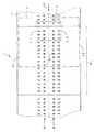
図2には、案内面17の平面図が示されている。ここではさらに、くわえづめ装置9の図示を省略して、くわえづめ装置9によって案内面17上を引かれていく処理可能な最大判の枚葉紙3と、また、ずっと小さい判の相応するそれぞれ1枚の枚葉紙3’が、案内面17に向かい合った任意の位置で示されている。この場合、それぞれの枚葉紙3,3’は、方向矢印24によって表される走行方向に案内面上で引っ張られる。案内面17には、ノズル25が通じていて、該ノズルを通って案内面17とそれぞれの枚葉紙3,3’との間に空気クッションを適切に形成するように空気が流される。ノズル25は、案内面17を構成する案内板にポンチ加工およびスタンピング加工を施すことによって形成されていることが好ましく、この案内板の下側には、ノズル25に吹き付け空気を供給するために設けられた(ここでは図示せず)吹き付け空気チャンバと前述の冷却剤容器23が配置されていることが好ましい。この案内板の有利な構成については、本出願人はすでにドイツ特許出願第19951894.7号に記載しており、その内容をここに引用する。
【0021】
有利な構成としては、枚葉紙3,3’の走行方向(方向矢印24で表す)に相前後してそれぞれ案内面17の一部を構成するモジュールが配列されている。該モジュールは、上述のように、冷却のための、および、ノズル25の各部分に吹き付け空気を供給するための各装置を備えている。前述のモジュールの1つはMiで表されている。
【0022】
図1で示された案内装置10を構成するために、特に案内面17の平坦な部分を有するモジュールと、枚葉紙3,3’の走行方向に湾曲された案内面17の部分を有するモジュールとが設けられている。ノズル25の配置は、ここでは枚葉紙の形態で存在している被印刷材料の、最終的には印刷ユニット2内で処理可能な様々な判に適合されている。この適合は次の点にある。すなわち、各被印刷材料の、走行方向に関して側方の各縁部が、(本例では枚葉紙3の縁部3.1,3.2、もしくは枚葉紙3’の縁部3’.1,3’.2)が、案内面17に沿う被印刷材料の経路上で常にノズル25の開口範囲の外側にあり、換言すれば、これらのノズルは、ノズルが存在しない回廊部に囲まれているマトリクスを形成し、該マトリクスは、案内面17の長手方向の長さに沿って延びている。したがって、この回廊部は、案内面17が閉じた表面を有する領域を案内面17上に形成している。
【0023】
処理される被印刷材料の判に適合した段階付けをする場合には、これらのノズル25が、複数の適当な回廊部を案内面17の長手方向中央部のこちら側および向こう側に備えるマトリクスを構成するようなノズルの配置が可能である。
【0024】
図2に示されている態様の場合には、ノズル25はマトリクスを構成し、該マトリクスは、枚葉紙3の処理可能な最大判よりも小さい判を有する枚葉紙3’の、走行方向に対して横方向に与えられた広がりの範囲内にある。この場合、ノズル25は、機械の動作時にこのノズル25を通って空気が流れる際に、側方向縁部3’.1,3’.2の各々に方向が合わされた気流を生成するように方向付けされている。
【0025】
図示されている実施形態では、ノズル25は、案内面17に沿って配置された2つのノズル列26.1,26.2を構成し、この場合、この2つのノズル列26.1,26.2のうちそれぞれ1つは、機械の動作時において気流が流通する際に、側部の各縁部3.1, 3.2もしくは3’.1,3’,2に垂直に向けられた気流を生成する。
【0026】
このようにしてマトリクスを2つのノズル列に減少させたことによって、また、縁部3.1,3.2もしくは3’.1,3’.2に対して垂直に向きを合わされた気流によって、それに対応してノズル列26.1,26.2の相互の距離を短く選択した場合には、これによって、処理可能な最大判寸法から、走行方向に対して横方向にノズル列26.1,26.2の広がりによって決定される最小判寸法にいたる全ての寸法の被印刷材料を、その被印刷材料の側方向縁部がノズル25の開口領域の勢力範囲に入ることなく走行面上を案内することができるという点で好ましい構成を生じる。
【0027】
それぞれのノズル列26.1,26.2のノズル25は、このノズル列内で、互いの距離ができるだけ短いことが好ましい。
【0028】
しかし、これらのノズルが上述のようなマトリクスの種類の1つでも構成する限り、また、装置の動作時に気流が通過する際に全ての処理可能な判寸法の枚葉紙の下側で空気クッションを形成するために適している限り、図2とは異なるノズルの構成および配置もまた本発明の範囲内にある。
【0029】
特にモジュールMiのような、モジュールにそれぞれ扇状に広がる気流を生成する個別ノズル25から構成されたノズル列26.1,26.2の代わりに、他の実施態様においては、このノズル列26.1,26.2のそれぞれを、側部の縁部3.1,3.2もしくは3’.1,3’.2に対して向きを揃えられた気流を生成する1つまたは複数の気流放出間隙に置き換えることができる。
【0030】
他の変形例では、全てのノズル25は、案内面17の長手方向中央に配置され、また、相前後して並ぶノズルが、走行方向に対して横方向に向いていて逆方向に向けられた気流を放出するように方向付けされることもできる。
【図面の簡単な説明】
【図1】 平坦状の被印刷材料処理機械の、排紙装置を含む部分を示す概略図である。
【図2】一実施形態にしたがって構成された案内面の、図1の矢印IIの方向にみた断面図である。
【符号の説明】
1 排紙装置
2 印刷ユニット
2.1 圧胴
2.2 ゴムブランケット胴
3,3’ 枚葉紙
3.1;3.2 枚葉紙3の側方の縁部
3’.1;3’.2 枚葉紙3の側方の縁部
4 チェーン搬送装置
5 回転方向矢印
6 搬送チェーン
7 駆動スプロケットホイール
8 ガイドスプロケットホイール
9 くわえづめ装置
9.1 くわえづめ
10 案内装置
11 枚葉紙制動装置
12 前縁ストッパ
13 後縁ストッパ
14 パイル
15 紙載せ台
16 昇降チェーン
17 案内面
18 接続管
19 乾燥機
20 粉かけ装置
21 入口管
22 出口管
23 冷却剤容器
24 方向矢印
25 ノズル
26.1;26.2 ノズル列
Mi 案内装置10のモジュール[0001]
BACKGROUND OF THE INVENTION
The present invention provides a guide surface for placing and guiding a sheet, and the sheet is forcibly guided and pulled by the edge of the sheet that precedes the running direction when the machine operates. A flat cover having a sliding guide surface and a nozzle that opens to the guide surface and that circulates an airflow to form an air cushion during operation of the machine between the guide surface and each sheet of paper. The present invention relates to a machine for processing a printing material, in particular to a guide device for a sheet processing printing machine, and also relates to a processing machine for a flat printing material provided with this kind of guide device.
[0002]
[Prior art]
A guide device of the kind described above is known, for example, from DE4209067C2. This publication deals with the problem that the sheet of paper drawn between the air cushion and the guide surface on the air cushion occupies an insufficient floating height in the hazardous area. This dangerous area includes the side edge of the sheet in the running direction of the sheet.
[0003]
In the aforementioned publication, in order to ensure a sufficient floating height in the region of the side edge of the sheet, according to the first embodiment, a braking rod on the guide surface along the side edge of the sheet It has been proposed to arrange. In the second embodiment, a side air blower that blows the outer edge of each sheet from the outside to the bottom is provided. With these embodiments, air stagnation occurs on the underside of the sheet of paper, which increases the flying height.
[0004]
In both of the above cases, an adjustment process is required to adapt to the size of the printed material being processed.
[0005]
[Problems to be solved by the invention]
The object of the present invention is to use the above-mentioned guiding device (described in “Technical field to which the invention belongs”) in order to guide a flat printing material of various sizes on a guiding surface. The construction is such that no auxiliary means have to be adjusted to fit the dimensions.
[0006]
[Means for Solving the Problems]
In order to achieve this object, in the guide device of the present invention, each edge of one of the printable materials of different sizes, which can be processed in different sizes, on the path of the print material along the guide surface. In addition, regions having closed surfaces are opposite on the guide surface.
[0007]
This solution starts with the following findings. That is, a negative pressure is formed in the opening region of the nozzle that opens in the guide surface and circulates the airflow in order to form an air cushion between the guide surface and the sheet of paper drawn on the guide surface. And, starting from the knowledge that the positive pressure required to guide the sheet in a floating state is first formed at some distance from each open area. The solution according to the invention prevents the edges of any printable material with various sizes, which are lateral in the running direction, from entering the negative pressure working area in the nozzle opening area. .
[0008]
In order to achieve this, it is possible to position these nozzles as follows. That is, when processing small can determine dimension than the outermost large format size, some of these nozzles are arranged on the inner side of the side edge portion of the smaller-size dimensions.
[0009]
In a preferred embodiment, the nozzle generates an air flow that is aligned with the lateral edges of the printed material as the air flows in conformity with the machine operating specifications during machine operation, and the nozzle is Limited to a region having a breadth in the transverse direction with respect to the running direction (direction arrow 24), the breadth having a printing material having a size smaller than the printing material having the largest size that can be processed, It exists in the range of the width | variety extended in a horizontal direction with respect to a running direction.
[0010]
In another preferred embodiment, the nozzle produces an air flow that is oriented perpendicularly to the lateral edges as the air flow conforms to the operating specifications of the machine.
[0011]
In another preferred configuration, the nozzles are within the width of the printing material having the smallest possible dimensions adapted to the process and extending transversely to the direction of travel.
[0012]
These embodiments combine some of the manufacturing technology and partly functional advantages over solutions for this purpose.
[0013]
The preferred embodiment of limiting these nozzles to only two nozzle rows arranged within a minimum size range is a conventional nozzle distributed over a large area of the guide surface to supply air to the nozzles. Compared with the case where it supplies, it requires less construction cost. By aligning the nozzles in this way, especially when the nozzles are closely adjacent to each other in the nozzle row as a preferred embodiment, this also results in an almost constant pressure transition in the running direction of each sheet. A functional advantage is obtained in that it occurs on the underside. As a result, the pressure profile generated on the underside of each sheet produces the desired effect by itself in the direction transverse to the direction of travel, and each sheet is reinforced in the direction of travel. Produces an effect. This has the effect of stabilizing the running of the sheet along the guide surface.
[0014]
DETAILED DESCRIPTION OF THE INVENTION
Hereinafter, the present invention will be described in detail according to an example of a guide device in a paper discharge device of a flat printing material processing machine based on the attached drawings.
[0015]
Hereinafter, the form of the sheet processing rotary press will be described based on a flat printing material processing machine.
[0016]
Here, as schematically shown in FIG. 1, the
[0017]
The transport chain 6 is guided by a chain guide rail along the path between the drive sprocket wheel 7 on the one hand and the redirecting
[0018]
In order to prevent the
[0019]
In order to prevent the
[0020]
FIG. 2 shows a plan view of the
[0021]
As an advantageous configuration, modules each constituting a part of the
[0022]
In order to construct the
[0023]
In the case of staging suitable for the size of the printing material to be processed, these
[0024]
In the case of the embodiment shown in FIG. 2, the
[0025]
In the illustrated embodiment, the
[0026]
By reducing the matrix to two nozzle rows in this way, the edges 3.1, 3.2 or 3 '. 1, 3 '. When the distance between the nozzle arrays 26.1 and 26.2 is selected to be short according to the airflow that is oriented perpendicularly to the direction 2, the traveling distance is increased from the maximum size that can be processed. The printing material of all dimensions up to the minimum size determined by the expansion of the nozzle rows 26.1, 26.2 in the direction transverse to the direction, the side edges of the printing material being the openings of the nozzles 25 A preferable configuration is obtained in that the vehicle can be guided on the running surface without entering the area of influence of the region.
[0027]
The
[0028]
However, as long as these nozzles are also configured in one of the matrix types as described above, and the air cushion underneath all processable size sheets when airflow passes during operation of the apparatus As long as it is suitable to form the nozzle configuration and arrangement different from FIG. 2 are also within the scope of the present invention.
[0029]
Instead of the nozzle row 26.1, 26.2, which consists of
[0030]
In another modification, all the
[Brief description of the drawings]
FIG. 1 is a schematic view showing a portion including a paper discharge device of a flat printing material processing machine.
2 is a cross-sectional view of the guide surface constructed in accordance with one embodiment, as viewed in the direction of arrow II in FIG.
[Explanation of symbols]
DESCRIPTION OF
Claims (3)
前記案内面に開口し、前記案内面と各枚葉紙との間に、機械の駆動時に空気クッションを形成するために気流を流通させるノズルと、
を有する、枚葉紙を処理する印刷機の案内装置において、
前記案内面(17)に沿う前記枚葉紙の経路上で、前記枚葉紙の前記走行方向(方向矢印24)に対して側方にある各縁部(3.1,3.2;3’.1,3’.2)に、前記案内面上で、前記ノズルの存在しない領域が相対し、前記ノズル(25)は第1及び第2のノズル列(26.1,26.2)の、前記走行方向(方向矢印24)に延びる2つのノズル列だけを構成し、前記第1のノズル列(26.1)は前記案内面(17)の前記走行方向に延びる中央線の一方の側に、前記第2のノズル列(26.2)は前記中央線の他方の側に位置し、前記第1及び第2のノズル列(26.1,26.2)からなる前記ノズル(25)が、前記処理に適合可能な最小の判寸法を有する枚葉紙の、前記走行方向(方向矢印24)に対して側方に延びる幅の範囲内にあるように使用されることを特徴とする案内装置。A guide surface for guiding put the sheet, with the guide on the inner surface, respective sheet is pulled preceding edge of Te leaf paper running direction odor during driving of the machine is forcibly guided And a guide to go
A nozzle that opens in the guide surface and circulates an airflow to form an air cushion when the machine is driven between the guide surface and each sheet;
In the guide device of a printing machine having, for processing the sheet, and
Wherein the guidance surfaces on the path of the sheet along the (17), the traveling direction (the direction of arrow 24) each edge in pairs to laterally of the sheet (3.1, 3.2; 3'.1, 3'.2) is opposed to the area where the nozzle does not exist on the guide surface, and the nozzle (25) is arranged in the first and second nozzle rows (26.1, 26.2). Only two nozzle rows extending in the running direction (direction arrow 24), and the first nozzle row (26.1) is one of the center lines of the guide surface (17) extending in the running direction. The second nozzle row (26.2) is located on the other side of the central line, and the nozzles (16.1, 26.2) are the nozzles (26.1, 26.2). 25), the sheet having the minimum determine dimensions adaptable to the process, width extending laterally with respect to the running direction (arrow 24) Guide device, characterized in that it is used to be within the scope.
Applications Claiming Priority (2)
| Application Number | Priority Date | Filing Date | Title |
|---|---|---|---|
| DE19960680.3 | 1999-12-15 | ||
| DE19960680 | 1999-12-15 |
Publications (3)
| Publication Number | Publication Date |
|---|---|
| JP2001206591A JP2001206591A (en) | 2001-07-31 |
| JP2001206591A5 JP2001206591A5 (en) | 2007-11-29 |
| JP5010066B2 true JP5010066B2 (en) | 2012-08-29 |
Family
ID=7932872
Family Applications (1)
| Application Number | Title | Priority Date | Filing Date |
|---|---|---|---|
| JP2000380126A Expired - Fee Related JP5010066B2 (en) | 1999-12-15 | 2000-12-14 | Printing machine guide apparatus for processing sheets and sheet processing machine equipped with the guide apparatus |
Country Status (3)
| Country | Link |
|---|---|
| US (1) | US6543765B2 (en) |
| JP (1) | JP5010066B2 (en) |
| DE (1) | DE10057570B4 (en) |
Families Citing this family (12)
| Publication number | Priority date | Publication date | Assignee | Title |
|---|---|---|---|---|
| JP2004137054A (en) * | 2002-10-18 | 2004-05-13 | Toshiba Corp | Paper sheets detecting device |
| DE10344715A1 (en) | 2003-09-26 | 2005-04-21 | Heidelberger Druckmasch Ag | Device for guiding a printing material |
| US7431290B2 (en) | 2003-09-26 | 2008-10-07 | Heidelberger Druckmaschinen Ag | Device for guiding a print carrier, method for producing a print carrier guiding device and machine for processing a print carrier |
| US7513499B2 (en) * | 2004-05-04 | 2009-04-07 | Heidelberger Druckmaschinen Ag | Sheet brake using a partitioned blower nozzle array |
| US7938764B2 (en) * | 2007-12-05 | 2011-05-10 | Greg Gale | Continuous feeder for paper folding machine and paper folding machine incorporating the same |
| US8083895B2 (en) * | 2008-04-18 | 2011-12-27 | Honeywell Asca Inc. | Sheet stabilization with dual opposing cross direction air clamps |
| US7892399B2 (en) * | 2008-05-29 | 2011-02-22 | Honeywell Asca Inc. | Local tension generating air stabilization system for web products |
| DE102012000952A1 (en) * | 2011-02-15 | 2012-08-16 | Heidelberger Druckmaschinen Ag | Apparatus for drying and dusting or powdering of printed or painted sheet in sheet-processing machine, is provided with dryer nozzles that are spaced apart in rows transversely to sheet transport direction |
| DE102012003270A1 (en) * | 2012-02-16 | 2013-08-22 | Heidelberger Druckmaschinen Ag | Device for transporting and / or aligning a sheet |
| CN103600579B (en) * | 2013-10-24 | 2017-01-04 | 沈阳达尔科技开发有限公司 | Air fluid type paper feeder in printer |
| US9670616B2 (en) | 2014-12-11 | 2017-06-06 | Georgia-Pacific Consumer Products Lp | Active web spreading and stabilization shower |
| FI126243B (en) * | 2015-01-14 | 2016-08-31 | Takso-Ohjelmistot Oy | Fiber web manipulation device and method |
Family Cites Families (13)
| Publication number | Priority date | Publication date | Assignee | Title |
|---|---|---|---|---|
| US3299535A (en) * | 1964-11-10 | 1967-01-24 | Ealing Corp | Frictionless track and gliders having air bearing surfaces for demonstrating mechanical principles |
| SE310117B (en) * | 1965-07-08 | 1969-04-14 | Svenska Flaektfabriken Ab | |
| DE3411029A1 (en) | 1984-03-24 | 1985-10-03 | M.A.N.- Roland Druckmaschinen AG, 6050 Offenbach | DEVICE FOR GUIDING SHEETS PRINTED ON SIDE AND BOTH SIDES |
| JPH0327394U (en) * | 1989-07-27 | 1991-03-19 | ||
| JPH04211943A (en) * | 1990-07-13 | 1992-08-03 | Sumitomo Heavy Ind Ltd | Paper discharge apparatus for sheet-fed press |
| DE4209067C2 (en) * | 1992-03-20 | 1997-03-13 | Kba Planeta Ag | Sheet guiding device |
| JPH07196197A (en) * | 1994-01-10 | 1995-08-01 | Ishikawajima Harima Heavy Ind Co Ltd | Sheet material floating conveying method and device |
| DE4406848C2 (en) * | 1994-03-03 | 1997-11-06 | Koenig & Bauer Albert Ag | Blow box for floating guiding of sheets or sheets |
| DE4433644B4 (en) * | 1994-09-21 | 2005-03-03 | Heidelberger Druckmaschinen Ag | Method and device for guiding a sheet |
| DE19607397A1 (en) * | 1996-02-28 | 1997-09-04 | Heidelberger Druckmasch Ag | Device and method for guiding sheet material in a printing press, in particular in a sheet-fed offset printing press |
| JP3238332B2 (en) * | 1996-10-04 | 2001-12-10 | 三菱重工業株式会社 | Sheet guide for sheet-fed printing press |
| EP0899228B1 (en) * | 1997-08-28 | 2004-04-14 | Heidelberger Druckmaschinen Aktiengesellschaft | Air cushion guiding device |
| JP3556816B2 (en) * | 1997-11-05 | 2004-08-25 | 三菱重工業株式会社 | Sheet guide device for sheet-fed printing press |
-
2000
- 2000-11-21 DE DE10057570A patent/DE10057570B4/en not_active Expired - Fee Related
- 2000-12-14 JP JP2000380126A patent/JP5010066B2/en not_active Expired - Fee Related
- 2000-12-15 US US09/739,542 patent/US6543765B2/en not_active Expired - Fee Related
Also Published As
| Publication number | Publication date |
|---|---|
| DE10057570B4 (en) | 2005-11-24 |
| US6543765B2 (en) | 2003-04-08 |
| JP2001206591A (en) | 2001-07-31 |
| US20010006276A1 (en) | 2001-07-05 |
| DE10057570A1 (en) | 2001-06-21 |
Similar Documents
| Publication | Publication Date | Title |
|---|---|---|
| JPH0558281U (en) | Sheet ejection device for printing machine | |
| JP5010066B2 (en) | Printing machine guide apparatus for processing sheets and sheet processing machine equipped with the guide apparatus | |
| JPH04226358A (en) | Sheet guide apparatus used at delivery of sheet-feed rotary printing machine | |
| JP3068519B2 (en) | Pneumatic sheet guide device installed in printing press | |
| JP4772370B2 (en) | Conveyor table | |
| JP2000053303A (en) | Paper discharge device and paper sheet printing machine having the same | |
| JP2899544B2 (en) | Paper processing machine paper ejection device | |
| JP2003334926A (en) | Sheet-fed rotary press | |
| JPH11227161A (en) | Sheet guiding device for printer | |
| JP2002096444A (en) | Paper delivery apparatus and machine provided with it to process plane printing body | |
| JP2000289184A (en) | Sheet delivering device for sheet-fed printer | |
| US6729233B2 (en) | Sheet guide device in a rotary printing machine | |
| JP3703803B2 (en) | Device for guiding the web material or sheet material while floating in the processing machine | |
| JP2001213545A (en) | Delivery of machine handling flat object to be printed | |
| JP2005320166A (en) | Device for conveying sheet by passing through printing technology machine | |
| US6702283B2 (en) | Device for decurling flat printing materials | |
| JP3621866B2 (en) | Sheet guide device for sheet-fed printing press | |
| JP4954439B2 (en) | Sheet processing machine with pneumatic sheet guide device | |
| JP3703796B2 (en) | Sheet paper guide device having a guide surface in a printing press | |
| JP3964304B2 (en) | Sheet material guide device | |
| US6726203B1 (en) | Sheet guide arrangement in a printing machine | |
| JP4169223B2 (en) | Suction device in sheet-fed rotary printing press | |
| JPH11138752A (en) | Sheet guiding apparatus for sheet-feed printer | |
| JP2003118072A (en) | Sheet guide device for sheet-feed press and method for controlling sheet guide device | |
| JP4406264B2 (en) | A rotary printing machine for processing sheets with a composite sheet guide device |
Legal Events
| Date | Code | Title | Description |
|---|---|---|---|
| A521 | Request for written amendment filed |
Free format text: JAPANESE INTERMEDIATE CODE: A523 Effective date: 20071015 |
|
| A621 | Written request for application examination |
Free format text: JAPANESE INTERMEDIATE CODE: A621 Effective date: 20071015 |
|
| RD03 | Notification of appointment of power of attorney |
Free format text: JAPANESE INTERMEDIATE CODE: A7423 Effective date: 20071015 |
|
| A977 | Report on retrieval |
Free format text: JAPANESE INTERMEDIATE CODE: A971007 Effective date: 20100729 |
|
| A131 | Notification of reasons for refusal |
Free format text: JAPANESE INTERMEDIATE CODE: A131 Effective date: 20100811 |
|
| A521 | Request for written amendment filed |
Free format text: JAPANESE INTERMEDIATE CODE: A523 Effective date: 20101020 |
|
| A02 | Decision of refusal |
Free format text: JAPANESE INTERMEDIATE CODE: A02 Effective date: 20110426 |
|
| A521 | Request for written amendment filed |
Free format text: JAPANESE INTERMEDIATE CODE: A523 Effective date: 20110629 |
|
| A911 | Transfer to examiner for re-examination before appeal (zenchi) |
Free format text: JAPANESE INTERMEDIATE CODE: A911 Effective date: 20110725 |
|
| A912 | Re-examination (zenchi) completed and case transferred to appeal board |
Free format text: JAPANESE INTERMEDIATE CODE: A912 Effective date: 20110930 |
|
| A521 | Request for written amendment filed |
Free format text: JAPANESE INTERMEDIATE CODE: A523 Effective date: 20120327 |
|
| A01 | Written decision to grant a patent or to grant a registration (utility model) |
Free format text: JAPANESE INTERMEDIATE CODE: A01 |
|
| A61 | First payment of annual fees (during grant procedure) |
Free format text: JAPANESE INTERMEDIATE CODE: A61 Effective date: 20120601 |
|
| R150 | Certificate of patent or registration of utility model |
Free format text: JAPANESE INTERMEDIATE CODE: R150 |
|
| FPAY | Renewal fee payment (event date is renewal date of database) |
Free format text: PAYMENT UNTIL: 20150608 Year of fee payment: 3 |
|
| LAPS | Cancellation because of no payment of annual fees |