EP2260817A2 - Rampe occultable pour l'accès à des véhicules de transport public - Google Patents
Rampe occultable pour l'accès à des véhicules de transport public Download PDFInfo
- Publication number
- EP2260817A2 EP2260817A2 EP10382158A EP10382158A EP2260817A2 EP 2260817 A2 EP2260817 A2 EP 2260817A2 EP 10382158 A EP10382158 A EP 10382158A EP 10382158 A EP10382158 A EP 10382158A EP 2260817 A2 EP2260817 A2 EP 2260817A2
- Authority
- EP
- European Patent Office
- Prior art keywords
- ramp
- box
- vehicle
- platforms
- platform
- Prior art date
- Legal status (The legal status is an assumption and is not a legal conclusion. Google has not performed a legal analysis and makes no representation as to the accuracy of the status listed.)
- Withdrawn
Links
Images


Classifications
-
- A—HUMAN NECESSITIES
- A61—MEDICAL OR VETERINARY SCIENCE; HYGIENE
- A61G—TRANSPORT, PERSONAL CONVEYANCES, OR ACCOMMODATION SPECIALLY ADAPTED FOR PATIENTS OR DISABLED PERSONS; OPERATING TABLES OR CHAIRS; CHAIRS FOR DENTISTRY; FUNERAL DEVICES
- A61G3/00—Ambulance aspects of vehicles; Vehicles with special provisions for transporting patients or disabled persons, or their personal conveyances, e.g. for facilitating access of, or for loading, wheelchairs
- A61G3/02—Loading or unloading personal conveyances; Facilitating access of patients or disabled persons to, or exit from, vehicles
- A61G3/06—Transfer using ramps, lifts or the like
- A61G3/061—Transfer using ramps, lifts or the like using ramps
-
- A—HUMAN NECESSITIES
- A61—MEDICAL OR VETERINARY SCIENCE; HYGIENE
- A61G—TRANSPORT, PERSONAL CONVEYANCES, OR ACCOMMODATION SPECIALLY ADAPTED FOR PATIENTS OR DISABLED PERSONS; OPERATING TABLES OR CHAIRS; CHAIRS FOR DENTISTRY; FUNERAL DEVICES
- A61G3/00—Ambulance aspects of vehicles; Vehicles with special provisions for transporting patients or disabled persons, or their personal conveyances, e.g. for facilitating access of, or for loading, wheelchairs
- A61G3/02—Loading or unloading personal conveyances; Facilitating access of patients or disabled persons to, or exit from, vehicles
- A61G3/06—Transfer using ramps, lifts or the like
- A61G3/067—Transfer using ramps, lifts or the like with compartment for horizontally storing the ramp or lift
-
- B—PERFORMING OPERATIONS; TRANSPORTING
- B60—VEHICLES IN GENERAL
- B60P—VEHICLES ADAPTED FOR LOAD TRANSPORTATION OR TO TRANSPORT, TO CARRY, OR TO COMPRISE SPECIAL LOADS OR OBJECTS
- B60P1/00—Vehicles predominantly for transporting loads and modified to facilitate loading, consolidating the load, or unloading
- B60P1/43—Vehicles predominantly for transporting loads and modified to facilitate loading, consolidating the load, or unloading using a loading ramp mounted on the vehicle
- B60P1/431—Vehicles predominantly for transporting loads and modified to facilitate loading, consolidating the load, or unloading using a loading ramp mounted on the vehicle the ramp being stored under the loading floor when not in use
Definitions
- the present invention relates to a concealable ramp for access to vehicles, particularly to public transport vehicles, suitable for being assembled in the floor of a door of the vehicle and capable of adopting two end positions, a first rest position, in which the ramp is folded in the vehicle, and a second operative position, in which the ramp is extended in a slanted plane from the floor of the vehicle to the surface of the ground on which the vehicle is located.
- ramps the structure of which is assembled under the chassis of a public transport vehicle having a low floor in order to cover the vertical distance between the floor and the ground or the bus stop platform, if any.
- the placement of ramps of this type makes the mechanisms causing the unfolding and withdrawal of the ramp deteriorate over time since they are exposed to the dirt and particles which are usually swept up by the bottom part of the chassis of the vehicle.
- Patent EP1166739 discloses a foldaway ramp comprising a supporting structure embedded within a recess located under the floor of a vehicle, a platform displaceable between a retracted position and an extracted position with respect to the supporting structure, parallel to the floor of the vehicle, electric actuator control means for moving said platform between the two positions and cam means for controlling the slant of said platform during the final phase of the displacement towards the extracted position, from a position parallel to said floor to a downwardly slanted position, in which the front edge of the platform rests on the ground, and the return to said retracted position by effect respectively of raising and lowering the rear side of said platform operated by said cam means.
- the mentioned cam means include upwardly slanted sliding surfaces located near the front edge of the supporting structure and having an arched profile, complementary elements having an arched shape with respect to the arched profile of the sliding surfaces, articulated to the rear edge of the platform and cooperating with said sliding surfaces by friction contact.
- the mentioned sliding surfaces and the complementary elements are located at the height of the ends of the front side of the supporting structure and of the rear side of said platform, respectively.
- the ramp and its mechanisms are arranged in a recess integrated in the floor of the vehicle to protect it from external agents, the length thereof is conditioned to the available inner space and for this reason, most of the ramps of this type formed by a platform housed inside the floor are highly slanted when the end thereof rests on the ground in the extracted position.
- a foldable ramp for use in the floor of a vehicle, comprising: a power source, a base, a first platform proximal the base and a second platform distal the base, a top and a bottom surface being distinguished in each of the platforms in an unfolded position, a linking device operatively connecting the first platform to the power source and provided with a fold facilitating arm, comprising a cable, connected to the second platform.
- the mentioned arm causes the second platform to pivot with respect to the first platform, and in the folded configuration the bottom surface of the first platform faces the bottom surface of the second platform and is parallel to the floor of the vehicle, the top surface of the second platform being coplanar with said floor.
- the ramp comprises a first platform capable of sloping downwards forming part of the actual floor of the vehicle, a second platform extensible and retractable with respect to the first platform beyond the end thereof, and fluid pressure force actuating means suitable for causing, under fluid pressure, the second platform to extend or retract along a first line of action, the actuating means being arranged to act along a second line of action which is transverse to the first line of action.
- the concealable ramp for access to vehicles object of the present invention eliminates all the mentioned drawbacks and at the same time presents an assembly solution which is easier and quicker and more comfortable to operate.
- the ramp in question is essentially characterized in that it is formed by two platforms which are laterally and telescopically coupled by means of an assembly of guides and bearings.
- both platforms are superimposed inside a box integral with the floor of the vehicle, such that the upper base of the box forms part of the floor itself, while in the second operative position both platforms protrude from the box in a slanted plane outside the vehicle and the upper one rests, in an articulated manner, at the ends of its rear edge on the side guides of the box, in the door of the vehicle in which the ramp is assembled, whereas the lower platform is arranged in a coplanar manner with respect to the upper platform, with its rear edge juxtaposed to the front edge of the upper platform and with its front edge resting on the ground.
- the assembly of both platforms is provided with drive means longitudinally arranged in the platforms and suitable for providing them with respective alternate folding and unfolding movements.
- the drive means comprise at least one first drive chain, assembled in a frame integral with the box of the ramp and associated with the upper platform; at least one second drive chain, associated with the lower platform and with the upper platform; and a single drive motor capable of operating the first drive chain, all of this arranged such that, when the two platforms of the ramp are introduced in the box in the rest position of the ramp, upon starting the drive motor both of them come out of the box simultaneously, the lower one being displaced at twice the speed of the upper one until both of them reach their position of outward maximum extension from the box, such that both platforms are arranged in a coplanar manner upon reaching said point of maximum extension.
- the first drive chain is linked to a drive bridge, integral with the upper platform, and to the shaft of the rear pulley of the second drive chain.
- the second drive chain is fixed at one of its points to a point of the box of the ramp and at another of its points to a point of the lower platform.
- the second drive chain is formed by a cable inextensible under traction.
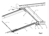
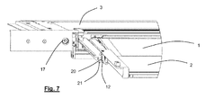
- the ramp object of the invention is essentially formed by an upper platform 1 and a lower platform 2, which are laterally and telescopically coupled by means of an assembly of guides 21 and bearings (see detail of Figure 7 ) and introduced, in the rest position of the ramp, in a box 3 suitably for being arranged integral with the floor of the vehicle, as can be seen in Figure 1 .
- the lower platform 2 is juxtaposed contiguous to the upper platform 1 and under it, both platforms are introduced, as has already been mentioned, inside the box 3 and the upper base 4 of the box 3 forms part of the actual floor of the vehicle and is preferably flush therewith.
- the ramp can be unfolded and adopt a second operative position, in which both platforms 1 and 2 protrude from the box 3 at the outer edge 6 of the latter and extend one after the other, forming a slanted plane from the floor of the vehicle to the ground on which the vehicle is located.
- this second position depicted in Figures 3 and 6
- the upper platform 1 rests in an articulated manner at the ends of its rear edge 5 on the side guides of the box 3, in the door of the vehicle in which the ramp is assembled, and the lower platform 2 is coplanar with the upper one and has its front edge 9 resting on the ground, not depicted.
- the ramp is provided with drive means longitudinally arranged in the sides of the platforms 1 and 2.
- such drive means comprise in each side of the box 3 a first drive chain 10 circulating around two shafts fixed to the box 3 and provided with respective pulleys 18 and 19.
- Each chain 10 is linked to a drive bridge 13, integral with the lower face of the upper platform 1.
- the drive means are provided in each side of the first platform 1 with a second drive chain 12, circulating around two shafts fixed to the platform 1 and provided with respective pulleys 14 and 20, said second chain 12 being fixed at one of its points to a point of the box 3 and at another of its points to a point of the lower platform 2.
- Said second chain 12 is preferably formed by a cable inextensible under traction.
- the drive means are preferably provided with a single drive motor, not depicted, engageable with the pulleys 18 of the first drive chain 10 through a clutch, which is known and not depicted in the drawings, operable by means of the key 16 which is introduced in the hole 17.
- both platforms 1 and 2 Upon starting the motor when the platforms 1 and 2 are withdrawn inside the box 3 in their rest position, both platforms 1 and 2 simultaneously start exiting outside the box 3, the upper platform 1 being displaced on the sides of the box 3, by means of a known and non-depicted system of guides and wheels, and the lower platform 2 being displaced on the sides of the upper platform 1, also by means of a known system of guides and wheels partially depicted in Figure 7 , which shows a track 21 over which the rear pulley 14 and the front pulley 20 of the second chain 12 move, causing the movement of the lower platform 2.
- the motor stops when the two platforms 1 and 2 also simultaneously reach their respective positions of maximum extension ( Figures 3 and 6 ) and, when the ramp is to be returned to its initial position, the drive chains rotate in a reverse direction to that of the operation of extension.
- the drive bridge 13 is provided at both ends with respective pivoting means 15 ( Figure 5 ) that facilitates said rotation.
Landscapes
- Health & Medical Sciences (AREA)
- Public Health (AREA)
- Life Sciences & Earth Sciences (AREA)
- Animal Behavior & Ethology (AREA)
- General Health & Medical Sciences (AREA)
- Veterinary Medicine (AREA)
- Engineering & Computer Science (AREA)
- Transportation (AREA)
- Mechanical Engineering (AREA)
- Vehicle Step Arrangements And Article Storage (AREA)
- Body Structure For Vehicles (AREA)
Applications Claiming Priority (1)
| Application Number | Priority Date | Filing Date | Title |
|---|---|---|---|
| ES200901400A ES2362294A1 (es) | 2009-06-10 | 2009-06-10 | "rampa ocultable para acceso a vehículos de transporte público". |
Publications (2)
| Publication Number | Publication Date |
|---|---|
| EP2260817A2 true EP2260817A2 (fr) | 2010-12-15 |
| EP2260817A3 EP2260817A3 (fr) | 2011-03-09 |
Family
ID=42668771
Family Applications (1)
| Application Number | Title | Priority Date | Filing Date |
|---|---|---|---|
| EP10382158A Withdrawn EP2260817A3 (fr) | 2009-06-10 | 2010-06-02 | Rampe occultable pour l'accès à des véhicules de transport public |
Country Status (2)
| Country | Link |
|---|---|
| EP (1) | EP2260817A3 (fr) |
| ES (1) | ES2362294A1 (fr) |
Cited By (8)
| Publication number | Priority date | Publication date | Assignee | Title |
|---|---|---|---|---|
| ITBS20110077A1 (it) * | 2011-05-26 | 2012-11-27 | Marco Rolfi Srl S | Metodo per il controllo dello scorrimento automatico di una pedana telescopica, pedana telescopica e veicolo che comprende tale pedana |
| EP2489568A3 (fr) * | 2011-02-21 | 2013-04-10 | Siemens Aktiengesellschaft | Rampe dotée d'une fixation mécanique variable |
| EP2730715A1 (fr) * | 2012-11-07 | 2014-05-14 | PMR Solutions | Dispositif d'acces a plateau coulissant |
| FR3019036A1 (fr) * | 2014-03-25 | 2015-10-02 | Gruau Laval | Dispositif d'embarquement d'une personne sur son fauteuil roulant a l'aide d'une rampe d'acces coulissante |
| GB2539624A (en) * | 2015-04-02 | 2016-12-28 | P S V Transp Systems Ltd | An access ramp |
| US9603758B1 (en) * | 2014-01-31 | 2017-03-28 | Vantage Mobility International, Llc | In-floor vehicle ramp |
| EP3542768A1 (fr) * | 2018-03-21 | 2019-09-25 | Masats, S.A. | Ensemble de rampe rétractable pour l'accès de personnes à des véhicules |
| EP3834793A1 (fr) * | 2019-12-09 | 2021-06-16 | The Braun Corporation | Assemblage de rampe à engrenage avec position de rampe et rails latéraux surélevés et procédé d'utilisation |
Citations (3)
| Publication number | Priority date | Publication date | Assignee | Title |
|---|---|---|---|---|
| EP1107720A1 (fr) | 1998-08-28 | 2001-06-20 | Passenger Lift Services Ltd. | Rampe d'acces |
| EP1166739A2 (fr) | 2000-06-21 | 2002-01-02 | ROLLON S.p.A. | Rampe escamotable pour fauteuils roulants d'handicapés et pour poussettes d'enfants adaptée aux véhicules à planchers bas |
| EP1704070A2 (fr) | 2004-01-08 | 2006-09-27 | Ricon Corp. | Rampe pliable |
Family Cites Families (4)
| Publication number | Priority date | Publication date | Assignee | Title |
|---|---|---|---|---|
| GB0100514D0 (en) * | 2001-01-09 | 2001-02-21 | Truck Align Company Ltd | Ramp asembly |
| US6484344B1 (en) * | 2001-08-10 | 2002-11-26 | Simon M. Cooper | Retractable access ramp |
| GB2405852A (en) * | 2003-09-13 | 2005-03-16 | Manganese Bronze Components Lt | Ramp assembly |
| US8926254B2 (en) * | 2005-11-08 | 2015-01-06 | Mobility Ventures Llc | Automotive vehicle having a power-actuated ramp |
-
2009
- 2009-06-10 ES ES200901400A patent/ES2362294A1/es active Pending
-
2010
- 2010-06-02 EP EP10382158A patent/EP2260817A3/fr not_active Withdrawn
Patent Citations (3)
| Publication number | Priority date | Publication date | Assignee | Title |
|---|---|---|---|---|
| EP1107720A1 (fr) | 1998-08-28 | 2001-06-20 | Passenger Lift Services Ltd. | Rampe d'acces |
| EP1166739A2 (fr) | 2000-06-21 | 2002-01-02 | ROLLON S.p.A. | Rampe escamotable pour fauteuils roulants d'handicapés et pour poussettes d'enfants adaptée aux véhicules à planchers bas |
| EP1704070A2 (fr) | 2004-01-08 | 2006-09-27 | Ricon Corp. | Rampe pliable |
Cited By (12)
| Publication number | Priority date | Publication date | Assignee | Title |
|---|---|---|---|---|
| EP2489568A3 (fr) * | 2011-02-21 | 2013-04-10 | Siemens Aktiengesellschaft | Rampe dotée d'une fixation mécanique variable |
| ITBS20110077A1 (it) * | 2011-05-26 | 2012-11-27 | Marco Rolfi Srl S | Metodo per il controllo dello scorrimento automatico di una pedana telescopica, pedana telescopica e veicolo che comprende tale pedana |
| WO2012160545A1 (fr) * | 2011-05-26 | 2012-11-29 | S. Marco-Rolfi S.R.L. | Procédé pour commander le coulissement automatique d'une rampe télescopique, rampe télescopique et véhicule comprenant une telle rampe |
| EP2730715A1 (fr) * | 2012-11-07 | 2014-05-14 | PMR Solutions | Dispositif d'acces a plateau coulissant |
| US9603758B1 (en) * | 2014-01-31 | 2017-03-28 | Vantage Mobility International, Llc | In-floor vehicle ramp |
| FR3019036A1 (fr) * | 2014-03-25 | 2015-10-02 | Gruau Laval | Dispositif d'embarquement d'une personne sur son fauteuil roulant a l'aide d'une rampe d'acces coulissante |
| GB2539624A (en) * | 2015-04-02 | 2016-12-28 | P S V Transp Systems Ltd | An access ramp |
| GB2539624B (en) * | 2015-04-02 | 2018-06-06 | P S V Transp Systems Limited | An access ramp |
| EP3542768A1 (fr) * | 2018-03-21 | 2019-09-25 | Masats, S.A. | Ensemble de rampe rétractable pour l'accès de personnes à des véhicules |
| WO2019180294A1 (fr) * | 2018-03-21 | 2019-09-26 | Masats, S.A. | Ensemble rampe escamotable pour permettre l'accès de personnes à des véhicules |
| US11918522B2 (en) | 2018-03-21 | 2024-03-05 | Masats, S.A. | Retractable ramp assembly for allowing people to enter vehicles |
| EP3834793A1 (fr) * | 2019-12-09 | 2021-06-16 | The Braun Corporation | Assemblage de rampe à engrenage avec position de rampe et rails latéraux surélevés et procédé d'utilisation |
Also Published As
| Publication number | Publication date |
|---|---|
| ES2362294A1 (es) | 2011-07-01 |
| EP2260817A3 (fr) | 2011-03-09 |
Similar Documents
| Publication | Publication Date | Title |
|---|---|---|
| EP2260817A2 (fr) | Rampe occultable pour l'accès à des véhicules de transport public | |
| US8359691B2 (en) | Compact folding slide-out ramp assembly | |
| JP4344816B2 (ja) | 折りたたみ式乗降台を備える車椅子リフト | |
| US6213486B1 (en) | Step assembly with concealed lower tread | |
| JP4703553B2 (ja) | 重ね式プラットフォームを有する車椅子アクセス装置 | |
| US6435804B1 (en) | Lifting apparatus | |
| US6086314A (en) | Foldable platform wheelchair lift | |
| US7326024B2 (en) | Wheelchair lift assembly having a compact stowed profile | |
| CN211765908U (zh) | 车辆 | |
| US7878519B2 (en) | Electric slide step for recreational vehicle | |
| US5224723A (en) | Vehicle step and platform apparatus | |
| US20090155037A1 (en) | Wheelchair lift apparatus | |
| US8438683B1 (en) | Sliding fold out ramp | |
| JP3382952B2 (ja) | 車体側壁 | |
| US20230391171A1 (en) | Vehicle with a platform unit on a bodywork opening | |
| EP1166739A2 (fr) | Rampe escamotable pour fauteuils roulants d'handicapés et pour poussettes d'enfants adaptée aux véhicules à planchers bas | |
| CN111483439A (zh) | 带有防洪,掉头,平行停车及摆脱深陷功能的自升式车辆 | |
| JP2010075567A (ja) | 車両用昇降装置 | |
| CA2174382A1 (fr) | Elevateur/rampe escamotable | |
| EP1121920A2 (fr) | Rampe rétractable pour véhicules à moteurs | |
| EP2165690A2 (fr) | Elévateur pour véhicules de transport de passagers | |
| JPH01106743A (ja) | 車両テールリフト | |
| RU194530U1 (ru) | Складная электрическая аппарель | |
| EP2631118A1 (fr) | Appareil de levage pour véhicule | |
| JP4128320B2 (ja) | 車椅子昇降装置 |
Legal Events
| Date | Code | Title | Description |
|---|---|---|---|
| PUAI | Public reference made under article 153(3) epc to a published international application that has entered the european phase |
Free format text: ORIGINAL CODE: 0009012 |
|
| AK | Designated contracting states |
Kind code of ref document: A2 Designated state(s): AL AT BE BG CH CY CZ DE DK EE ES FI FR GB GR HR HU IE IS IT LI LT LU LV MC MK MT NL NO PL PT RO SE SI SK SM TR |
|
| AX | Request for extension of the european patent |
Extension state: BA ME RS |
|
| PUAL | Search report despatched |
Free format text: ORIGINAL CODE: 0009013 |
|
| AK | Designated contracting states |
Kind code of ref document: A3 Designated state(s): AL AT BE BG CH CY CZ DE DK EE ES FI FR GB GR HR HU IE IS IT LI LT LU LV MC MK MT NL NO PL PT RO SE SI SK SM TR |
|
| AX | Request for extension of the european patent |
Extension state: BA ME RS |
|
| STAA | Information on the status of an ep patent application or granted ep patent |
Free format text: STATUS: THE APPLICATION IS DEEMED TO BE WITHDRAWN |
|
| 18D | Application deemed to be withdrawn |
Effective date: 20110910 |