EP2259957B1 - Steering column for a motor vehicle - Google Patents
Steering column for a motor vehicle Download PDFInfo
- Publication number
- EP2259957B1 EP2259957B1 EP08873726A EP08873726A EP2259957B1 EP 2259957 B1 EP2259957 B1 EP 2259957B1 EP 08873726 A EP08873726 A EP 08873726A EP 08873726 A EP08873726 A EP 08873726A EP 2259957 B1 EP2259957 B1 EP 2259957B1
- Authority
- EP
- European Patent Office
- Prior art keywords
- steering column
- counter
- securing part
- setting unit
- unit
- Prior art date
- Legal status (The legal status is an assumption and is not a legal conclusion. Google has not performed a legal analysis and makes no representation as to the accuracy of the status listed.)
- Active
Links
- 230000007246 mechanism Effects 0.000 claims description 52
- 238000006073 displacement reaction Methods 0.000 claims description 29
- 238000005452 bending Methods 0.000 claims description 12
- 230000015572 biosynthetic process Effects 0.000 claims description 2
- 238000010521 absorption reaction Methods 0.000 description 22
- 238000005265 energy consumption Methods 0.000 description 5
- 239000002184 metal Substances 0.000 description 5
- 230000003313 weakening effect Effects 0.000 description 5
- 238000010276 construction Methods 0.000 description 2
- 239000000463 material Substances 0.000 description 2
- 230000021715 photosynthesis, light harvesting Effects 0.000 description 2
- 238000000926 separation method Methods 0.000 description 2
- 208000027418 Wounds and injury Diseases 0.000 description 1
- 238000000418 atomic force spectrum Methods 0.000 description 1
- 230000000903 blocking effect Effects 0.000 description 1
- 238000005520 cutting process Methods 0.000 description 1
- 230000006378 damage Effects 0.000 description 1
- 238000007373 indentation Methods 0.000 description 1
- 208000014674 injury Diseases 0.000 description 1
- 238000005457 optimization Methods 0.000 description 1
- 238000003825 pressing Methods 0.000 description 1
- 230000000750 progressive effect Effects 0.000 description 1
- 238000005096 rolling process Methods 0.000 description 1
- 230000009466 transformation Effects 0.000 description 1
- 238000000844 transformation Methods 0.000 description 1
- 238000003466 welding Methods 0.000 description 1
Images


Classifications
-
- B—PERFORMING OPERATIONS; TRANSPORTING
- B62—LAND VEHICLES FOR TRAVELLING OTHERWISE THAN ON RAILS
- B62D—MOTOR VEHICLES; TRAILERS
- B62D1/00—Steering controls, i.e. means for initiating a change of direction of the vehicle
- B62D1/02—Steering controls, i.e. means for initiating a change of direction of the vehicle vehicle-mounted
- B62D1/16—Steering columns
- B62D1/18—Steering columns yieldable or adjustable, e.g. tiltable
- B62D1/19—Steering columns yieldable or adjustable, e.g. tiltable incorporating energy-absorbing arrangements, e.g. by being yieldable or collapsible
- B62D1/195—Yieldable supports for the steering column
-
- B—PERFORMING OPERATIONS; TRANSPORTING
- B62—LAND VEHICLES FOR TRAVELLING OTHERWISE THAN ON RAILS
- B62D—MOTOR VEHICLES; TRAILERS
- B62D1/00—Steering controls, i.e. means for initiating a change of direction of the vehicle
- B62D1/02—Steering controls, i.e. means for initiating a change of direction of the vehicle vehicle-mounted
- B62D1/16—Steering columns
- B62D1/18—Steering columns yieldable or adjustable, e.g. tiltable
- B62D1/184—Mechanisms for locking columns at selected positions
-
- B—PERFORMING OPERATIONS; TRANSPORTING
- B62—LAND VEHICLES FOR TRAVELLING OTHERWISE THAN ON RAILS
- B62D—MOTOR VEHICLES; TRAILERS
- B62D1/00—Steering controls, i.e. means for initiating a change of direction of the vehicle
- B62D1/02—Steering controls, i.e. means for initiating a change of direction of the vehicle vehicle-mounted
- B62D1/16—Steering columns
- B62D1/18—Steering columns yieldable or adjustable, e.g. tiltable
- B62D1/185—Steering columns yieldable or adjustable, e.g. tiltable adjustable by axial displacement, e.g. telescopically
-
- B—PERFORMING OPERATIONS; TRANSPORTING
- B62—LAND VEHICLES FOR TRAVELLING OTHERWISE THAN ON RAILS
- B62D—MOTOR VEHICLES; TRAILERS
- B62D1/00—Steering controls, i.e. means for initiating a change of direction of the vehicle
- B62D1/02—Steering controls, i.e. means for initiating a change of direction of the vehicle vehicle-mounted
- B62D1/16—Steering columns
- B62D1/18—Steering columns yieldable or adjustable, e.g. tiltable
- B62D1/187—Steering columns yieldable or adjustable, e.g. tiltable with tilt adjustment; with tilt and axial adjustment
Definitions
- the invention relates to a steering column for a motor vehicle, which is adjustable at least in its longitudinal direction, comprising a support unit which is connectable to the chassis of the motor vehicle, an actuating unit which is arranged between side cheeks of the support unit, and a clamping mechanism in the open State, the actuator relative to the support unit at least in the longitudinal direction of the steering column is adjustable and in the closed state, the adjusted position of the actuator relative to the support unit is detected and which comprises a clamping bolt which passes through openings in the side walls of the support unit and the opening and closing of the clamping mechanism is rotated about its axis, wherein at least one arranged between the side walls of the support unit and adjusted by the rotation of the clamping bolt when opening and closing the clamping mechanism locking part is present, which in the closed state of the Clamping mechanism engages in a connected to the actuator Gegenfestitatiil or at least in a case of a vehicle crash incipient displacement of the actuator relative to the support unit with the counter-locking part engages and which is distanced in the open state
- Adjustable steering columns are used to adjust the position of the steering wheel to the driver's seating position and are known in various embodiments.
- adjustable steering columns which are adjustable only in the length or height or inclination direction
- adjustable in both the length and height or inclination steering columns are known.
- such an adjustable steering column goes out of the EP 0 802 104 A1 out.
- the clamping mechanism In the open state of the clamping mechanism is an adjusting unit which rotatably supports the steering spindle, relative to a chassis-fixed support unit both in the direction of a length adjustment and in the direction of a height or tilt adjustment of the steering column adjustable.
- the clamping mechanism comprises in the manner of a multi-plate clutch cooperating intersecting plate packs.
- an energy absorption device of the steering column consists for example in that the support unit is designed as a kind of slide, which is displaceably mounted on a rigidly mounted on the chassis chassis unit, wherein between the chassis unit and the support unit an energy absorption device is formed, for example, a bending strip.
- a clamping wedge which is inserted in the event of a crash in a gap between the actuator and the support unit.
- the clamping wedge is connected to the clamping bolt or a moving axially with this part and is moved axially when closing the clamping mechanism together with the clamping bolt so that a contact surface of the clamping wedge is applied to a contact surface of the actuator to the clamping wedge in case of a crash incipient displacement of the actuator of this take.
- an energy absorption device for absorbing energy in the event of a crash in which a locking element attached to the adjusting unit, with which a counter-locking element is engaged in the closed state of the locking device used to determine the adjusted position of the steering column, is connected to the setting unit such that it is displaceable in the longitudinal direction of the steering column in the event of a crash with energy absorption relative to the actuator.
- Another with respect to the adjusting unit with energy absorption sliding locking element of a locking device is from the EP 1 464 560 A2 known.
- an analog device is present.
- the required space of the steering column is increased and the tooth widths of the cooperating teeth can be formed only relatively small, whereby the additional holding force of the crash-locking device is limited.
- the GB 2291840 A discloses a steering column of the type mentioned, in which the counter-fixing part is fixedly attached to the adjusting unit.
- the object of the invention is to provide a steering column of the type mentioned, which allows for a training with a relatively small space in the event of a crash reliable engagement of the locking part in the counter-locking part. According to the invention, this is achieved by a steering column with the features of claim 1.
- the counter-locking part is arranged on a plane parallel to the axis of the clamping bolt wall, in particular the upper or lower side wall of the actuator or is formed by this, with a space-saving design of the steering column yet a relatively large engagement width between the locking part and the counter-locking part be formed.
- the locking part engages in the Gegenfest scholaril after closing the clamping mechanism either directly form-fitting or is the locking part initially only frictionally in contact with the Gegenfestberichtil. In the latter case, however, is brought by the resilient contact the locking member at an incipient displacement of the actuator relative to the support unit, as it can be done when exceeding the holding force of the clamping mechanism, for example in the event of a vehicle crash, in a positive engagement with the counter-locking part. In this case, the maximum value of the possible displacement can be defined until the positive engagement is achieved.
- a plurality of engagement elements are introduced into the counter-locking part, in which a shaped element, for example a nose, of the locking part can engage.
- the distance of the recesses defines the maximum possible displacement to the positive engagement between the locking and counter-locking part.
- the advantage here is that a variety of known in the art possibilities for forming the clamping and clamping mechanism or the clamping mechanism with which the support unit is locked relative to the actuating unit, are used.
- the locking can be done both via a positive connection, for example via a toothing, as well as a frictional connection.
- the control of the clamping mechanism can be done via the known combination of wedge disk and cam member or via rolling elements that roll along predetermined paths and allow appropriate clamping of the clamping system.
- a clamping bolt is provided, which is aligned transversely to the direction of displacement of the actuator relative to the support unit and when changing from the position in which the displacement of the support unit relative to the actuating unit is possible, in the position in which the displacement of the support unit the actuator is blocked, performs a rotational movement about its own axis. This rotational movement is used to adjust the locking part in the ready position or out of the ready position out.
- the counter-fixing part in the event of a vehicle crash, is displaceable with respect to the adjusting unit while consuming energy. So there is a displaceable under energy absorption connection of the counter-locking part with the actuator.
- the displacement counteracting force is much larger, preferably more than an order of magnitude greater than the usual force required for longitudinal adjustment of the actuator relative to the support unit in the open state of the clamping mechanism. If in the event of a crash, the holding force of the clamping mechanism is overcome and acts on the counter-locking part, a force which exceeds the force, which counteracts the displacement of the counter-locking part, the counter-locking part can be moved with energy consumption relative to the actuator.
- the Schmidtberichtberichtil and the actuator are thus separate parts.
- the displaceable under energy absorption connection of the counter-locking part is designed with the actuator such that the displacement of the actuator relative to the chassis-fixed support unit or the vehicle chassis counteracting forces are in the range of 500N to 10000N.
- the actuator may also be overcome. If the forces are of this magnitude, the risk of injury to the driver is minimized.
- special predetermined or adjustable force profiles over the displacement path are desired, which in the ideal case can even be adjustable during the crash.
- the counter-fixing part is designed as a U-shaped bent sheet metal element with two legs.
- the sheet metal element is aligned in the installed position so that the arcuate portion of the sheet metal element is arranged in the direction of the driver, or to the steering wheel end of the steering shaft.
- a first leg also referred to as a tab, is designed as a sheet-metal strip and comprises a plurality of engagement elements.
- a second leg is connected to the actuator which rotatably supports the steering spindle directly or indirectly, and has two weakening lines parallel to one another and to the other leg, for example indentations between which a tear-open tab is formed.
- the tab is displaced by the positive connection between an engagement element and the form-fitting element, so that the arc section also shifts and the tear tab is torn out of the second leg. Due to the large number of engagement elements, the force path profile and the total path available for the energy consumption are always the same regardless of the adjustment position of the actuating unit relative to the support unit. Instead of a tear tab could also be provided a pure bending tab or a combination thereof. A number of advantages are associated with this preferred embodiment. So little additional space is needed. In particular, the clamping bolt does not have to be extended and the steering column should not be made wider.
- the engagement in the clamping system is minimal and the assembly is easy.
- This feature combines two functions.
- a carriage is provided between the actuator and the support unit.
- the setting unit is adjusted relative to the carriage.
- the carriage is moved relative to the support unit via intermediate energy absorption means. It must be ensured that during the energy absorption no uncontrolled displacement of the actuator relative to the carriage takes place.
- both functions are combined in one element, the U-shaped bent sheet metal element.
- Next is a slide, at least for purely length-adjustable steering columns, not required.
- a steering column according to the invention can only be adjustable in length or in addition to the longitudinal adjustability in height or inclination.
- the clamping bolt for this purpose pass through slots in the side walls of the support unit, which extend in the direction of the height or inclination adjustment.
- an intermediate unit is provided, which is adjustable relative to the support unit in the direction of the height or inclination adjustment, wherein the actuating unit relative to the intermediate unit in the longitudinal direction of the steering column or steering spindle is adjustable.
- the intermediate unit can be omitted and the side cheeks of the support unit can be clamped in the closed state of the clamping mechanism directly to the actuator, as is also already known.
- the support unit is fixed in a possible embodiment rigidly on the chassis of the motor vehicle.
- energy-absorbing means for example at least one bending strip, can advantageously be provided between the support unit and the chassis unit.
- Such constructions are known.
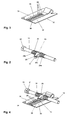
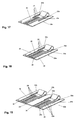
- a first embodiment of a steering column according to the invention is in the Fig. 1 to 6 shown, wherein the FIGS. 2 and 4 Variants of the clamping bolt 12 illustrate this embodiment.
- the steering column comprises a support unit 1, which is fastened to the chassis of a motor vehicle.
- a steering shaft 2, at the steering wheel side end 3, a steering wheel is attached, is rotatably supported by a shell unit or actuator 4, which is supported by the support unit 1.
- the adjusting unit 4 relative to the support unit 1 in the longitudinal direction 6 and in the direction 7 of the height or tilt adjustment is adjustable.
- the adjusting unit 4 is arranged between side cheeks 8, 9 of the support unit 1, in openings 10, 11 are arranged, which are in the form of in the direction 7 of the height or inclination adjustment extending slots and which passes through a clamping bolt 12 of the clamping mechanism 5 become.
- the clamping bolt 12 passes through further in the form of elongated holes extending in the longitudinal direction 6 holes 13, 14 in side cheeks 15, 16 of the adjusting unit. 4
- the clamping bolt 12 is held by the edges of the interspersed through him openings 10, 11 in the side walls 8, 9 of the support unit 1 in a respective set height or inclination position of the steering column in the longitudinal direction of the steering column immovably.
- an intermediate unit 40 is arranged in the illustrated embodiment.
- This has side cheeks 41, 42, which are arranged between the respective side cheek 8, 9 of the support unit 1 and the setting unit 4.
- the clamping bolt 12 passes through round holes in the side walls 41, 42.
- the intermediate unit 40 is pivotable relative to the support unit 1 about a pivot axis 30 in the direction 7 of the height or inclination adjustment.
- the side cheeks 41, 42 are guided relative to the setting unit 4 by projecting webs which engage in longitudinal grooves 43 on the side surfaces of the setting unit 4.
- the locking elements of the clamping mechanism 5 are thus brought together by an axial displacement of the clamping bolt 12 or by an axial displacement relative to the clamping bolt 12 with each other.
- the actuating lever 18 is by means of a formed as a polygonal surface approach 21 of the clamping bolt 12, as in FIG. 4 is illustrated, rotatably connected to the clamping bolt 12.
- the actuating lever 18 for non-rotatable connection with the clamping bolt 12 for example, engage over the bolt head 22 of the clamping bolt 12, be welded to the clamping bolt 12 or be connected via a roller or a knurl on the clamping bolt 12 by a press fit with this.
- a corresponding clamping bolt 12 without additionally formed surface projection 21 is in FIG. 2 illustrated.
- a locking part 23 is arranged on the clamping bolt 12. This is located in the region between the side walls 8, 9 of the support unit 1.
- the locking member 23 is pivotally mounted relative to the clamping bolt 12 about its axis on the clamping bolt 12, conveniently as shown by the clamping bolt 12 passes through an opening in the locking part 23.
- a spring element 24 is further arranged on both sides of the locking part 23, the clamping bolt 12 helical spring-like surrounding portions 24a, 24b and a connecting this bracket portion 24c, wherein the sections 24a, 24b, 24c consist of a continuous spring wire.
- the portions 24a, 24b are non-rotatably connected to the clamping bolt 12, for example by clamping, by positive engagement or by material bond, e.g. Bonding or spot welding.
- the bracket portion 24c extends through a groove 25 in the locking part 23rd
- the locking member 23 is held without acting external force in a certain angular position relative to the clamping bolt 12 and is against the restoring force of the spring element 24 deflected from this.
- a counter-locking part 26 is held, on the parallel to the axis of the clamping bolt 12 lying upper side wall 27 of the actuator 4.
- the Schmidtfest scholaril 26 has a tab with a plurality of longitudinally 6 of the steering column or steering shaft 2 with respective Distance successive engagement elements 29 on these engagement elements 29 are provided for the positive engagement of the locking part 23.
- these engagement elements 29 are formed by slot-shaped recesses extending through the material of the tab into which a protruding nose 31 of the locking part 23 can be inserted.
- the recesses could for example also be in the form of groove-like depressions or simply punched holes.
- the locking part 23 In the open state of the clamping mechanism 5, the locking part 23 is lifted from the counter-locking part 26, see. Fig. 6 , By the rotation of the clamping bolt 12 when closing the clamping mechanism 5, the locking part 23 is pressed against the counter-locking part 26.
- two cases may occur: On the one hand, the mutual position between the locking part 23 and counter-locking part 26 (due to the current setting position of the steering column in the longitudinal direction) be just so that the locking member 23 in one of the engagement elements 29 engages, so immediately a positive engagement between the locking part 23 and counter-locking part 26 is formed.
- the nose 31 can come to rest on a web between two successive engagement elements 29.
- the locking part 23 is pressed by the spring force of the spring element 24 to the counter-locking part 26.
- a displacement of the actuator 4 relative to the support unit 1 would be used until the Nose 31 passes into the region above an engagement element 29, whereupon it is brought by the spring force of the spring element 24 into engagement with the engagement element 29.
- the lug-shaped counter-locking part 26 is connected to the setting unit 4 such that it is displaceable in the longitudinal direction 6 of the steering column or steering spindle 2 with energy consumption relative to the setting unit 4.
- a leg of the U-shaped counter-locking part 26 is connected via a bend with a tear plate 32, which in turn is rigidly connected to the side wall 27 of the actuator 4.
- the tear plate 32 could also form a portion of the sidewall 27 of the actuator.
- the tear plate 32 has, for example, formed by stamping lines of weakness 33, 34, in 3 and 4 are indicated by dashed lines. As a result, a tear tab 28 is delimited. By a sufficiently strong train on the tab-shaped counter-locking part 26, the tear tab 28 along the lines of weakness 33, 34 under energy dissipation more and more are demolished, forming a tab-like Gegenfestberichtil 26 continuing tab. Another part of energy dissipation is the bending work done in shifting the point of the bend.
- the tab 28a may be at least partially formed as a bending tab, which is separated from the base plate 32a by slots or slots 33a, 34a in a designated bending area (see. Fig. 17 ).
- such energy absorbing elements can also be arranged in parallel on a base plate, wherein each energy absorbing element pure bending or bending transformations with subsequent cutting / tearing operations or pure tearing operations can be provided and the same or different energy absorption mechanisms can be used in the individual energy absorbing elements. It is possible to provide two energy absorption elements or more energy absorbing elements in parallel on a single Aufr Employplatt 32 or base plate 32a or provided on separate juxtaposed tear or base plates.
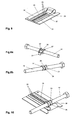
- a second embodiment of the invention is in the Fig. 7 to 12 shown.
- the difference from the embodiment described above is mainly in the nature of the connection of the locking member 23 with the clamping bolt 12.
- the locking member 23 is in turn pivotally mounted on the clamping bolt 12.
- the clamping bolt is provided with an externally radially projecting pin 35 which engages in a slot 36 in the locking part 23 and at a pivoting of the locking member 23 relative to the clamping bolt 12 moves in this.
- a spring element 37 in the form of a bow spring is attached to the clamping bolt 12, wherein ends of the spring wire protrude into radial bores of the clamping bolt 12.
- the spring element 37 extending over the locking part 23 presses the locking part 23 against the counter-locking part 26 (cf. Fig. 10 and 11 ).
- the pin 35 is pivoted and pivots to one end of the slot 36 (located in FIG Fig. 8b slightly below the pin 35), whereupon the locking part 23 is pivoted and lifted off the counter-locking part 26.
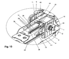
- FIG. 13 shows by way of example an embodiment in which on the side facing away from the locking part 23 side of the counter-locking part 26, a bolt 38 is mounted, which extends into an extending in the longitudinal direction 6 slot 39 in the side wall 27 of the actuator 4.
- the bolt 38 is in the initial state in an enlarged region of the slot 39. With a displacement of the bolt 38 relative to the slot 39, there is a widening of the slot 39, whereby energy is consumed.
- Fig. 20 joins the slot 39, a strip area 39a, which is separated when retracting the bolt 38.
- a first energy absorption level can be set in a targeted manner by widening the slot 39 and in a second section a second energy absorption level can be set by means of the separation of the strip area 39a.
- the width of the slot by the displacement of the bolt according to the desired course of energy absorption. For example, the width may be continuously reduced towards the end of the crash path to achieve progressive energy absorption.
- the strip area 39a can also be represented as a slot with a very narrow width, for example less than half the diameter, or the thickness of the bolt 38.
- a longitudinal groove is arranged on the upper side and / or lower side of the strip area 39a.
- the groove is dimensioned according to its depth and / or width.
- the U-shaped counter-locking member 26 surrounds the locking part 23.
- the engaging elements 29 having the portion abuts against the upper side wall of the actuating unit 4.
- the tear plate with the tear tab 28 is attached to the side facing away from the steering shaft side of the clamping bolt 12 on the adjusting unit 4.
- a tear tab 28 for example, a bending tab or a combination of a bending and tear tab could be provided.
- the counter-locking part 26 is disposed respectively on the upper side wall 27 of the actuator 4.
- the counter-locking part could also be arranged on another parallel to the axis of the clamping bolt 12 lying wall of the adjusting unit 4, for example, from the lower side wall.
- the engagement elements 29 of the counter-locking part 26 could also be designed differently than in the form of recesses, wherein the locking part has a matched engagement element to a respect to the longitudinal direction 6 of the steering column or steering shaft 2 immovable engagement, in particular positive engagement, between the locking member 23 and To allow counter-locking part 26.
- a longitudinal extent of the counter-locking part 26 running in the longitudinal direction 6 would again be a plurality of engagement positions for the locking part 23.
- the engagement elements 29 of the counter-locking part 26 could also be formed by teeth of a toothing and the locking part 23 could be formed with a corresponding counter-toothing.
- intermediate unit 40 could also be omitted.
- the side cheeks 8, 9 of the support unit 1 could then be pressed on both sides in the closed state of the clamping mechanism 5 directly to the control unit 4.
- the pivot axis between the actuator 4 and the support unit 1 could be formed in this case, for example, by a universal joint, via which the steering shaft 2 is connected to a further portion of the steering shaft.
- this pivot axis could also be formed by a mounted on the support unit 1 pivot pin, which passes through an extending in the longitudinal direction 6 slot in the actuator 4.
- the invention can also be used with steering columns, which are adjustable only in the longitudinal direction 6.
- the clamping bolt 12 could then in the form of round holes formed openings 10, 11 in the side walls 8, 9 of the support unit 1 prevail.
- the locking member 23 is pivotally connected to the clamping bolt 12 and, for example, itself is designed resiliently.
- a design could be provided in which a locking member 23 is pivotally connected to the clamping bolt 12 and when opening and closing the clamping mechanism 5, a drive element, such as the actuating lever 18, directly on a clamping member, such as the wedge or cam 20 acts and this twisted.
- the clamping bolt 12 could be taken by the rotation of the clamping part of this, with the interposition of a spring element, so that the locking member 23 is pressed in the closed state of the clamping mechanism 5 of this spring element to the counter-locking part 26.
- the displaceability of the counter-locking part relative to the actuating unit has a defined, predetermined or adjustable force-displacement curve.
- the size of the force acting on the actuator in the longitudinal direction of the steering column in the direction of the vehicle front, from which there is a displacement of the counter-locking part relative to the actuator is preferably less than 10000N, for example, may be less than 5000N.
Description
Die Erfindung bezieht sich auf eine Lenksäule für ein Kraftfahrzeug, die zumindest in ihrer Längsrichtung verstellbar ist, umfassend eine Trageinheit , die mit dem Chassis des Kraftfahrzeugs verbindbar ist, eine Stelleinheit, die zwischen Seitenwangen der Trageinheit angeordnet ist, und einen Spannmechanismus, in dessen geöffnetem Zustand die Stelleinheit gegenüber der Trageinheit zumindest in die Längsrichtung der Lenksäule verstellbar ist und in dessen geschlossenem Zustand die eingestellte Position der Stelleinheit gegenüber der Trageinheit festgestellt ist und die einen Spannbolzen umfasst, welcher Öffnungen in den Seitenwangen der Trageinheit durchsetzt und beim Öffnen und Schließen des Spannmechanismus um seine Achse gedreht wird, wobei mindestens ein zwischen den Seitenwangen der Trageinheit angeordnetes und durch die Drehung des Spannbolzens beim Öffnen und Schließen des Spannmechanismus verstelltes Feststellteil vorhanden ist, welches im geschlossenen Zustand des Spannmechanismus in ein mit der Stelleinheit verbundenes Gegenfeststellteil eingreift oder zumindest bei einer im Falle eines Fahrzeugcrashes einsetzenden Verschiebung der Stelleinheit gegenüber der Trageinheit mit dem Gegenfeststellteil in Eingriff gelangt und welches im geöffneten Zustand des Spannmechanismus vom Gegenfeststellteil distanziert ist.The invention relates to a steering column for a motor vehicle, which is adjustable at least in its longitudinal direction, comprising a support unit which is connectable to the chassis of the motor vehicle, an actuating unit which is arranged between side cheeks of the support unit, and a clamping mechanism in the open State, the actuator relative to the support unit at least in the longitudinal direction of the steering column is adjustable and in the closed state, the adjusted position of the actuator relative to the support unit is detected and which comprises a clamping bolt which passes through openings in the side walls of the support unit and the opening and closing of the clamping mechanism is rotated about its axis, wherein at least one arranged between the side walls of the support unit and adjusted by the rotation of the clamping bolt when opening and closing the clamping mechanism locking part is present, which in the closed state of the Clamping mechanism engages in a connected to the actuator Gegenfeststellteil or at least in a case of a vehicle crash incipient displacement of the actuator relative to the support unit with the counter-locking part engages and which is distanced in the open state of the clamping mechanism of the counter-locking part.
Verstellbare Lenksäulen dienen zur Anpassung der Position des Lenkrades an die Sitzposition des Fahrers und sind in unterschiedlichen Ausführungsformen bekannt. Neben verstellbaren Lenksäulen, die nur in die Längen- oder Höhen- bzw. Neigungsrichtung verstellbar sind, sind sowohl in die Längen- als auch Höhen- bzw. Neigungsrichtung verstellbare Lenksäulen bekannt. Beispielsweise geht eine derartige verstellbare Lenksäule aus der
Für verstellbare Lenksäulen sind bereits verschiedene Vorrichtungen vorgeschlagen worden, um im Falle eines Fahrzeugcrashes eine zusätzliche Haltekraft gegen eine Verschiebung der Stelleinheit gegenüber der Trageinheit zu bewirken, damit eine unkontrollierte Verstellung der Lenksäule verhindert wird, wodurch auch eine kontrollierte Energieabsorption durch eine Energieabsorptionseinrichtung der Lenksäule ermöglicht wird. Eine solche Energieabsorptionseinrichtung besteht beispielsweise darin, dass die Trageinheit als Art Schlitten ausgebildet ist, der verschiebbar an einer starr am Fahrzeugchassis angebrachten Chassiseinheit verschiebbar gelagert ist, wobei zwischen der Chassiseinheit und der Trageinheit eine Energieabsorptionseinrichtung ausgebildet ist, beispielsweise ein Biegestreifen.For adjustable steering columns various devices have already been proposed to provide an additional holding force against displacement of the vehicle in the event of a vehicle crash Actuate against the support unit to cause uncontrolled adjustment of the steering column is prevented, whereby a controlled energy absorption is made possible by an energy absorption device of the steering column. Such an energy absorption device consists for example in that the support unit is designed as a kind of slide, which is displaceably mounted on a rigidly mounted on the chassis chassis unit, wherein between the chassis unit and the support unit an energy absorption device is formed, for example, a bending strip.
Eine derartige Ausbildung geht aus der
Aus der
Aus der
Aus der
Die
Aufgabe der Erfindung ist es, eine Lenksäule der eingangs genannten Art bereitzustellen, die bei einer Ausbildung mit einem relativ geringen Bauraum im Crashfall einen zuverlässigen Eingriff des Feststellteils in das Gegenfeststellteil ermöglicht. Erfindungsgemäß gelingt dies durch eine Lenksäule mit den Merkmalen des Anspruchs 1.The object of the invention is to provide a steering column of the type mentioned, which allows for a training with a relatively small space in the event of a crash reliable engagement of the locking part in the counter-locking part. According to the invention, this is achieved by a steering column with the features of
Dadurch, dass das Gegenfeststellteil an einer parallel zur Achse des Spannbolzens liegenden Wand, insbesondere der oberen oder unteren Seitenwand, der Stelleinheit angeordnet ist oder von dieser gebildet wird, kann bei einer platzsparenden Ausbildung der Lenksäule dennoch eine relativ große Eingriffsbreite zwischen dem Feststellteil und dem Gegenfeststellteil ausgebildet werden. Beim Öffnen und Schließen des Spannmechanismus, der im geschlossenen Zustand einer Verstellung der Stelleinheit gegenüber der Trageinheit entgegenwirkt, wird der Spannbolzen um seine Achse verdreht und mit ihm das, vorzugsweise auf oder am Spannbolzen angeordnete, Feststellteil. Im geöffneten Zustand ist das Feststellteil vom Gegenfeststellteil distanziert, also außer Eingriff gebracht. Im geschlossenen Zustand des Spannmechanismus wird das Feststellteil, vorzugsweise federnd, in Kontakt mit dem Gegenfeststellteil gebracht.The fact that the counter-locking part is arranged on a plane parallel to the axis of the clamping bolt wall, in particular the upper or lower side wall of the actuator or is formed by this, with a space-saving design of the steering column yet a relatively large engagement width between the locking part and the counter-locking part be formed. When opening and closing the clamping mechanism, which counteracts in the closed state an adjustment of the actuator relative to the support unit, the clamping bolt is rotated about its axis and with it the, preferably arranged on or on the clamping bolt, locking part. In the open state, the locking part of the counter-fixing part is distanced, that is disengaged. When closed the clamping mechanism, the locking part, preferably resilient, brought into contact with the counter-locking part.
In einer bevorzugten Ausführungsform greift das Feststellteil in das Gegenfeststellteil nach dem Schließen des Spannmechanismus entweder direkt formschlüssig ein oder steht das Feststellteil zunächst nur reibschlüssig in Kontakt mit dem Gegenfeststellteil. Im letzteren Fall wird jedoch durch den federnden Kontakt das Feststellteil bei einer beginnenden Verschiebung der Stelleinheit gegenüber der Trageinheit, wie sie bei Überschreitung der Haltekraft des Spannmechanismus, beispielsweise im Falles eines Fahrzeugcrashs erfolgen kann, in einen formschlüssigen Eingriff mit dem Gegenfeststellteil gebracht. Dabei kann der maximale Wert der möglichen Verschiebung bis zum Erreichen des formschlüssigen Eingriffs definiert werden.In a preferred embodiment, the locking part engages in the Gegenfeststellteil after closing the clamping mechanism either directly form-fitting or is the locking part initially only frictionally in contact with the Gegenfeststellteil. In the latter case, however, is brought by the resilient contact the locking member at an incipient displacement of the actuator relative to the support unit, as it can be done when exceeding the holding force of the clamping mechanism, for example in the event of a vehicle crash, in a positive engagement with the counter-locking part. In this case, the maximum value of the possible displacement can be defined until the positive engagement is achieved.
Hierzu werden mit Vorteil in das Gegenfeststellteil mehrere Eingriffselemente, im einfachsten Fall Aussparungen, eingebracht, in die ein Formelement, beispielweise eine Nase, des Feststellteils eingreifen kann. Der Abstand der Aussparungen definiert den maximal möglichen Verschiebeweg bis zum formschlüssigen Eingriff zwischen Feststell- und Gegenfeststellteil.For this purpose, a plurality of engagement elements, in the simplest case recesses, are introduced into the counter-locking part, in which a shaped element, for example a nose, of the locking part can engage. The distance of the recesses defines the maximum possible displacement to the positive engagement between the locking and counter-locking part.
Von Vorteil ist dabei, dass eine Vielzahl von im Stand der Technik bekannter Möglichkeiten zur Ausbildung des Spann- und Klemmechanismus bzw. des Spannmechanismus, mit dem die Trageinheit gegenüber der Stelleinheit verriegelt wird, einsetzbar sind. Die Verriegelung kann dabei sowohl über einen Formschluss, beispielsweise über eine Verzahnung, als auch über einen Reibschluss erfolgen. Auch die Ansteuerung des Spannmechanismus kann über die bekannte Kombination aus Keilscheibe und Nockenteil erfolgen oder auch über Wälzkörper, die entlang vorgegebener Bahnen rollen und eine entsprechende Verspannung des Spannsystems ermöglichen. Entscheidend ist, dass ein Spannbolzen vorhanden ist, der quer zur Verschieberichtung der Stelleinheit gegenüber der Trageinheit ausgerichtet ist und beim Wechsel von der Stellung, in der die Verschiebung der Trageinheit gegenüber der Stelleinheit ermöglicht ist, in die Stellung, in der die Verschiebung der Trageinheit gegenüber der Stelleinheit blockiert ist, eine Drehbewegung um seine eigene Achse ausführt. Diese Drehbewegung wird dazu genutzt, das Feststellteil in die Bereitschaftsstellung oder aus der Bereitschaftsstellung heraus zu verstellen.The advantage here is that a variety of known in the art possibilities for forming the clamping and clamping mechanism or the clamping mechanism with which the support unit is locked relative to the actuating unit, are used. The locking can be done both via a positive connection, for example via a toothing, as well as a frictional connection. Also, the control of the clamping mechanism can be done via the known combination of wedge disk and cam member or via rolling elements that roll along predetermined paths and allow appropriate clamping of the clamping system. It is crucial that a clamping bolt is provided, which is aligned transversely to the direction of displacement of the actuator relative to the support unit and when changing from the position in which the displacement of the support unit relative to the actuating unit is possible, in the position in which the displacement of the support unit the actuator is blocked, performs a rotational movement about its own axis. This rotational movement is used to adjust the locking part in the ready position or out of the ready position out.
Gemäß der Erfindung ist vorgesehen, dass das Gegenfeststellteil im Falle eines Fahrzeugcrashes unter Energieaufzehrung gegenüber der Stelleinheit verschiebbar ist. Es liegt also eine unter Energieaufnahme verschiebbare Verbindung des Gegenfeststellteils mit der Stelleinheit vor. Dabei ist die der Verschiebung entgegenwirkende Kraft viel größer, vorzugsweise mehr als eine Größenordnung größer, als die übliche zur Längsverstellung der Stelleinheit gegenüber der Trageinheit im geöffneten Zustand des Spannmechanismus erforderliche Kraft. Wenn im Crash-Fall die Haltekraft des Spannmechanismus überwunden wird und auf das Gegenfeststellteil eine Kraft einwirkt, die die Kraft überschreitet, weiche der Verschiebung des Gegenfeststellteils entgegenwirkt, so kann das Gegenfeststellteil unter Energieaufzehrung gegenüber der Stelleinheit verschoben werden. Das Gegenfeststellteil und die Stelleinheit sind somit separate Teile.According to the invention, it is provided that, in the event of a vehicle crash, the counter-fixing part is displaceable with respect to the adjusting unit while consuming energy. So there is a displaceable under energy absorption connection of the counter-locking part with the actuator. The displacement counteracting force is much larger, preferably more than an order of magnitude greater than the usual force required for longitudinal adjustment of the actuator relative to the support unit in the open state of the clamping mechanism. If in the event of a crash, the holding force of the clamping mechanism is overcome and acts on the counter-locking part, a force which exceeds the force, which counteracts the displacement of the counter-locking part, the counter-locking part can be moved with energy consumption relative to the actuator. The Gegenfeststellteil and the actuator are thus separate parts.
Vorzugsweise ist die unter Energieaufnahme verschiebbare Verbindung des Gegenfeststellteils mit der Stelleinheit derart ausgelegt, dass die einer Verschiebung der Stelleinheit gegenüber der chassisfesten Trageinheit bzw. dem Fahrzeugchassis entgegenwirkenden Kräfte im Bereich von 500N bis 10000N liegen. Durch diese Kräfte werden auch gegebenenfalls weitere vorhandene -insbesonders reibschlüssig wirkende - Haltekräfte des Spannmechanismus überwunden. Sind die Kräfte in dieser Größenordnung, so ist die Verletzungsgefahr für den Fahrer minimiert. Zur Optimierung sind dabei spezielle vorgegebene oder einstellbare Kraftverläufe über den Verschiebeweg gewünscht, die im Idealfall sogar während des Crashs einstellbar sein können.Preferably, the displaceable under energy absorption connection of the counter-locking part is designed with the actuator such that the displacement of the actuator relative to the chassis-fixed support unit or the vehicle chassis counteracting forces are in the range of 500N to 10000N. As a result of these forces, further existing holding forces of the clamping mechanism, which are in particular frictionally engaged, may also be overcome. If the forces are of this magnitude, the risk of injury to the driver is minimized. For optimization, special predetermined or adjustable force profiles over the displacement path are desired, which in the ideal case can even be adjustable during the crash.
In einer vorteilhaften Ausbildung ist das Gegenfeststellteil als etwa U-förmig gebogenes Blechelement mit zwei Schenkeln ausgebildet. Das Blechelement ist in Einbaulage so ausgerichtet, dass der bogenförmige Abschnitt des Blechelements ist in Richtung zum Fahrer, bzw. zum lenkradseitigen Ende der Lenkspindel hin angeordnet ist. Ein erster Schenkel, auch als Lasche bezeichnet, ist als Blechstreifen ausgebildet und umfasst mehrere Eingriffselemente. Ein zweiter Schenkel ist mit der Stelleinheit, die direkt oder indirekt die Lenkspindel drehbar lagert, verbunden und weist zwei zueinander und zum anderen Schenkel parallele Schwächungslinien, beispielsweise Einkerbungen, zwischen denen eine Aufreißlasche gebildet ist, auf. Im Fall, dass das Spannsystem geschlossen ist und eine Verschiebung der Stelleinheit gegenüber der Trageinheit erfolgt, wird durch den Formschluss zwischen einem Eingriffselement und dem Formschlusselement die Lasche verschoben, so dass der der Bogenabschnitt sich ebenfalls verschiebt und die Aufreißlasche aus dem zweiten Schenkel herausgerissen wird. Durch die Vielzahl von Eingriffselementen ist der Kraft-Wegverlauf und der gesamte für die Energieaufzehrung zur Verfügung stehende Weg immer gleich, unabhängig von der Verstellposition der Stelleinheit gegenüber der Trageinheit. Anstelle einer Aufreißlasche könnte auch eine reine Biegelasche oder eine Kombination hiervon vorgesehen sein. Mit dieser bevorzugten Ausführungsform sind eine Reihe von Vorteilen verbunden. So wird kaum zusätzlicher Bauraum benötigt. Insbesondere muss der Spannbolzen nicht verlängert werden und die Lenksäule nicht breiter gebaut werden. Auch ist der Eingriff in das Spannsystem minimal und die Montage einfach. Mit Hilfe dieser Ausführung sind zwei Funktionen kombiniert. Beim Stand der Technik, beispielsweise der
Eine erfindungsgemäße Lenksäule kann nur längsverstellbar oder zusätzlich zur Längsverstellbarkeit auch in der Höhe bzw. Neigung verstellbar sein. Beispielsweise kann der Spannbolzen zu diesem Zweck Langlöcher in den Seitenwangen der Trageinheit durchsetzen, welche sich in Richtung der Höhen- bzw. Neigungsverstellung erstrecken. Denkbar und möglich ist es, dass eine Zwischeneinheit vorgesehen ist, welche gegenüber der Trageinheit in Richtung der Höhen- bzw. Neigungsverstellung verstellbar ist, wobei die Stelleinheit gegenüber der Zwischeneinheit in Längsrichtung der Lenksäule bzw. Lenkspindel verstellbar ist. Derartige Konstruktionen sind bekannt. In einer anderen Ausführungsform kann die Zwischeneinheit entfallen und die Seitenwangen der Trageinheit können im geschlossenen Zustand des Spannmechanismus direkt mit der Stelleinheit verspannt sein, wie dies ebenfalls bereits bekannt ist.A steering column according to the invention can only be adjustable in length or in addition to the longitudinal adjustability in height or inclination. For example, the clamping bolt for this purpose pass through slots in the side walls of the support unit, which extend in the direction of the height or inclination adjustment. It is conceivable and possible that an intermediate unit is provided, which is adjustable relative to the support unit in the direction of the height or inclination adjustment, wherein the actuating unit relative to the intermediate unit in the longitudinal direction of the steering column or steering spindle is adjustable. Such constructions are known. In another embodiment, the intermediate unit can be omitted and the side cheeks of the support unit can be clamped in the closed state of the clamping mechanism directly to the actuator, as is also already known.
Die Trageinheit wird in einer möglichen Ausführungsform starr am Chassis des Kraftfahrzeugs befestigt. In einer anderen Ausführungsform ist die Trageinheit an einer Chassiseinheit, welche wiederum starr am Chassis des Kraftfahrzeugs befestigbar ist, gehalten, wobei sie im Normalbetrieb gegenüber der Chassiseinheit unverschiebbar ist und im Crashfall (=bei Überschreiten eines Schwellenwerts der einwirkenden Kraft) gegenüber der Chassiseinheit in Richtung zur Fahrzeugfront verschiebbar ist. Hierbei können vorteilhafterweise energieaufzehrende Mittel, beispielsweise mindestens ein Biegestreifen, zwischen der Trageinheit und der Chassiseinheit vorgesehen sein. Derartige Konstruktionen sind bekannt.The support unit is fixed in a possible embodiment rigidly on the chassis of the motor vehicle. In another embodiment, the support unit is held on a chassis unit, which in turn is rigidly attachable to the chassis of the motor vehicle, being immovable in normal operation relative to the chassis unit and in the event of a crash (= when a threshold value of the applied force) with respect to the chassis unit in the direction is displaceable to the front of the vehicle. In this case, energy-absorbing means, for example at least one bending strip, can advantageously be provided between the support unit and the chassis unit. Such constructions are known.
Weitere Vorteile und Einzelheiten der Erfindung werden im Folgenden anhand der beiliegenden Zeichnung erläutert. In dieser zeigen:
-
Fig. 1 ein erstes Ausführungsbeispiel einer Lenksäule gemäß der Erfindung in Schrägsicht; -
Fig. 2 eine Schrägsicht eines spannbolzens mit dem darauf angeordneten Feststellteil; -
Fig. 3 eine Schrägsicht des Gegenfeststellteils; -
Fig. 4 das auf einem Spannbolzen angeordnete Feststellteil im Eingriff mit dem Gegenfeststellteil; -
Fig. 5 einen Teil der Lenksäule in Seitenansicht, teilweise aufgeschnitten, in der Schließstellung des Betätigungshebels; -
Fig. 6 eine Ansicht entsprechendFig. 5 , aber in der Offenstellung des Betätigungshebels; -
Fig. 7 eine Schrägsicht einer Lenksäule gemäß einem zweiten Ausführungsbeispiel der Erfindung; -
Fig. 8a und b Schrägsichten des Spannbolzens mit dem Feststellteil gemäß dieser zweiten Ausführungsform der Erfindung; -
Fig. 9 eine Schrägsicht des Gegenfeststellteils; -
Fig. 10 das auf dem Spannbolzen angeordnete Feststellteil in Eingriff mit dem Gegenfeststellteil; -
Fig. Seitenansichten von Teilen der Lenksäule gemäß der zweiten Ausführungsform, teilweise aufgeschnitten, in der Schließstellung und Offenstellung des Betätigungshebels;11und 12 -
Fig. 13 einen Teil einer Schrägsicht einer Lenksäule gemäß einer dritten Ausführungsform, ein Teil der Stelleinheit der Übersichtlichkeit halber entfernt und das Gegenfeststellteil in der Längsmitte aufgeschnitten; -
Fig. 14 eine Schrägsicht einer Lenksäule gemäß einer vierten Ausführungsform; -
Fig. 15 einen Teil einer Seitenansicht der Lenksäule gemäß dieser vierten Ausführungsform, teilweise aufgeschnitten; -
Fig. 16 eine Draufsicht auf die Lenksäule gemäß der vierten Ausführungsform; -
Fig. 17 eine Schrägsicht eines Gegenfeststellteils gemäß einer modifizierten Ausführungsform; -
Fig. 18 eine Schrägsicht eines Gegenfeststellteils gemäß einer weiteren modifizierten Ausführungsform; -
Fig. 19 eine Schrägsicht eines Gegenfeststellteils gemäß einer weiteren modifizierten Ausführungsform; -
Fig. 20 ein Teil einer Schrägsicht einer Lenksäule gemäß einer Variante der dritten Ausführungsform, ein Teil der Stelleinheit der Übersichtlichkeit halber entfernt und das Gegenfeststellteil in der Längsmitte aufgeschnitten.
-
Fig. 1 a first embodiment of a steering column according to the invention in oblique view; -
Fig. 2 an oblique view of a clamping bolt with the locking part arranged thereon; -
Fig. 3 an oblique view of the Gegenfeststellteils; -
Fig. 4 arranged on a clamping bolt locking part in engagement with the Gegenfeststellteil; -
Fig. 5 a part of the steering column in side view, partially cut, in the closed position of the actuating lever; -
Fig. 6 a view accordinglyFig. 5 but in the open position of the operating lever; -
Fig. 7 an oblique view of a steering column according to a second embodiment of the invention; -
Fig. 8a and b Oblique views of the clamping bolt with the locking part according to this second embodiment of the invention; -
Fig. 9 an oblique view of the Gegenfeststellteils; -
Fig. 10 arranged on the clamping bolt locking part in engagement with the Gegenfeststellteil; -
FIGS. 11 and 12 Side views of parts of the steering column according to the second embodiment, partially cut away, in the closed position and open position of the actuating lever; -
Fig. 13 a part of an oblique view of a steering column according to a third embodiment, a part of the adjusting unit for clarity removed and cut the Gegenfeststellteil in the longitudinal center; -
Fig. 14 an oblique view of a steering column according to a fourth embodiment; -
Fig. 15 a part of a side view of the steering column according to this fourth embodiment, partially cut away; -
Fig. 16 a plan view of the steering column according to the fourth embodiment; -
Fig. 17 an oblique view of a Gegenfeststellteils according to a modified embodiment; -
Fig. 18 an oblique view of a Gegenfeststellteils according to another modified embodiment; -
Fig. 19 an oblique view of a Gegenfeststellteils according to another modified embodiment; -
Fig. 20 a part of an oblique view of a steering column according to a variant of the third embodiment, a part of the adjusting unit for clarity removed and cut the Gegenfeststellteil in the longitudinal center.
Ein erstes Ausführungsbeispiel einer Lenksäule gemäß der Erfindung ist in den
Die Lenksäule umfasst eine Trageinheit 1, die am Chassis eines Kraftfahrzeugs befestigbar ist. Eine Lenkspindel 2, an deren lenkradseitigen Ende 3 ein Lenkrad anbringbar ist, ist von einer Manteleinheit bzw. Stelleinheit 4 drehbar gelagert, welche von der Trageinheit 1 getragen wird. Im geöffneten Zustand eines Spannmechanismus 5 ist die Lenksäule in ihrer Längsrichtung 6 (= achsiale Richtung der Lenkspindel 2) und in Richtung 7 der Höhe bzw. Neigung verstellbar. Hierbei ist die Stelleinheit 4 gegenüber der Trageinheit 1 in die Längsrichtung 6 und in die Richtung 7 der Höhen- bzw. Neigungsverstellung verstellbar.The steering column comprises a
Die Stelleinheit 4 ist zwischen Seitenwangen 8, 9 der Trageinheit 1 angeordnet, in Öffnungen 10, 11 angeordnet sind, welche in Form von in Richtung 7 der Höhen- bzw. Neigungsverstellung sich erstreckenden Langlöchern ausgebildet sind und welche von einem Spannbolzen 12 des Spannmechanismus 5 durchsetzt werden. Der Spannbolzen 12 durchsetzt weiters in Form von in die Längsrichtung 6 sich erstreckenden Langlöchern ausgebildete Öffnungen 13, 14 in Seitenwangen 15, 16 der Stelleinheit 4.The adjusting
Der Spannbolzen 12 wird durch die Ränder der von ihm durchsetzten Öffnungen 10, 11 in den Seitenwangen 8, 9 der Trageinheit 1 in einer jeweiligen eingestellten Höhen- bzw. Neigungsposition der Lenksäule in Längsrichtung der Lenksäule unverschiebbar gehalten.The clamping
Zwischen der Trageinheit 1 und der Stelleinheit 4 ist im gezeigten Ausführungsbeispiel eine Zwischeneinheit 40 angeordnet. Diese weist Seitenwangen 41, 42 auf, die zwischen der jeweiligen Seitenwange 8, 9 der Trageinheit 1 und der Stelleinheit 4 angeordnet sind. Der Spannbolzen 12 durchsetzt Rundlöcher in den Seitenwangen 41, 42. Die Zwischeneinheit 40 ist gegenüber der Trageinheit 1 um eine Schwenkachse 30 in die Richtung 7 der Höhen- bzw. Neigungsverstellung verschwenkbar. In Längsrichtung 6 der Lenksäule sind die Seitenwangen 41, 42 gegenüber der Stelleinheit 4 durch vorspringende Stege geführt, die in Längsnuten 43 an den Seitenflächen der Stelleinheit 4 eingreifen.Between the carrying
Im geschlossenen Zustand des Spannmechanismus werden die Seitenwangen 8, 9 der Trageinheit 1 beidseitig gegen die Seitenwangen 41, 42 der Zwischeneinheit 40 und diese gegen die Stelleinheit 4 verspannt, wobei die zusammenwirkenden Reibflächen reibschlüssig wirkende Arretierelemente des spannmechanismus darstellen. Auf dem Spannbolzen angeordnete, gegen die Außenseiten der Seitenwangen 8, 9 angedrückte Andruckteile 17 bilden weitere mit den Seitenwangen 8, 9 zusammenwirkende Reibflächen aus, wodurch weitere reibschlüssig wirkende Arretierelemente der Spanneinrichtung gebildet werden. Prinzipiell denkbar und möglich wäre es, weitere Reibflächen durch zusammenwirkende Lamellen auszubilden, wie dies bekannt ist.In the closed state of the clamping mechanism, the
Zum Öffnen und Schließen des Spannmechanismus dient ein Betätigungshebel 18, durch dessen Verschwenkung in bekannter Weise eine mit einer Gegenscheibe 19 (=Keilscheibe) zusammenwirkende Nockenscheibe 20 verdreht wird, wobei beim Schließen des Spannmechanismus die beiden Scheiben 19, 20 auseinandergespreizt werden.To open and close the clamping mechanism is an actuating
Die Arretierelemente des Spannmechanismus 5 werden somit durch eine achsiale Verschiebung des Spannbolzens 12 bzw. durch eine achsiale Verschiebung gegenüber dem Spannbolzen 12 miteinander in Eingriff gebracht.The locking elements of the
Anstelle eines Betätigungshebels 18 könnte auch eine andere Betätigung, beispielsweise elektrische Betätigung des Spannmechanismus vorgesehen sein. Anstelle einer Keil- oder Nockenscheibe 20 könnte auch ein anderer Mechanismus zur achsialen Verschiebung des Spannbolzens 12 bzw. zur achsialen Verschiebung von Arretierelementen gegenüber dem Spannbolzen 12 vorgesehen sein.Instead of an
Der Betätigungshebel 18 ist mittels eines als Mehrkant ausgebildeten Flächenansatzes 21 des Spannbolzens 12, wie er in
Durch die drehfeste Verbindung des Betätigungshebels 18 mit dem Spannbolzen 12 wird dieser beim Öffnen und Schließen des Spannmechanismus um seine Achse gedreht.Due to the rotationally fixed connection of the actuating
Auf dem Spannbolzen 12 ist ein Feststellteil 23 angeordnet. Dieses befindet sich im Bereich zwischen den Seitenwangen 8, 9 der Trageinheit 1. Das Feststellteil 23 ist gegenüber dem Spannbolzen 12 um dessen Achse verschwenkbar auf dem Spannbolzen 12 angeordnet, günstigerweise indem wie dargestellt der Spannbolzen 12 eine Öffnung im Feststellteil 23 durchsetzt.On the clamping
Auf dem Spannbolzen 12 ist weiters ein Federelement 24 angeordnet. Dieses weist beidseitig des Feststellteils 23 den Spannbolzen 12 schraubenfederartig umgebende Abschnitte 24a, 24b und einen diese verbindenden Bügelabschnitt 24c auf, wobei die Abschnitte 24a, 24b, 24c aus einem durchgehenden Federdraht bestehen. Die Abschnitte 24a, 24b sind unverdrehbar mit dem Spannbolzen 12 verbunden, beispielsweise klemmend, durch Formschluss oder durch Stoffschluss, z.B. Verklebung oder Punktverschweißung. Der Bügelabschnitt 24c erstreckt sich durch eine Nut 25 im Feststellteil 23.On the clamping
Dadurch wird das Feststellteil 23 ohne einwirkende äußere Kraft in einer bestimmten Winkellage gegenüber dem Spannbolzen 12 gehalten und ist gegen die Rückstellkraft des Federelements 24 aus dieser auslenkbar.As a result, the locking
An der Stelleinheit 4 ist weiters ein Gegenfeststellteil 26 gehalten, und zwar an der parallel zur Achse des Spannbolzens 12 liegenden oberen Seitenwand 27 der Stelleinheit 4. Das Gegenfeststellteil 26 weist eine Lasche mit einer Mehrzahl von in Längsrichtung 6 der Lenksäule bzw. Lenkspindel 2 mit jeweiligem Abstand aufeinanderfolgenden Eingriffselementen 29 auf diese Eingriffselemente 29 sind zum formschlüssigen Eingriff des Feststellteils 23 vorgesehen. Im gezeigten Ausführungsbeispiel werden diese Eingriffselemente 29 von durch das Material der Lasche durchgehenden, schlitzförmigen Ausnehmungen gebildet, in welche eine vorspringende Nase 31 des Feststellteils 23 einführbar ist. Die Ausnehmungen könnten beispielsweise auch in Form von nutartigen Vertiefungen oder einfach als gestanzte Löcher ausgeführt sein.On the
Im geöffneten Zustand des Spannmechanismus 5 ist das Feststellteil 23 vom Gegenfeststellteil 26 abgehoben, vgl.
Entweder gleich nach dem Schließen des Spannmechanismus 5 oder zumindest nach einer anfänglichen geringen Verschiebung der Stelleinheit 4 gegenüber der Trageinheit 1, welche kleiner als der Abstand von zwei aufeinanderfolgenden Eingriffselementen 29 ist, kommt es somit im Crashfall zu einem formschlüssigen Eingriff des Feststellteils 23 mit dem Gegenfeststellteil 26.Either immediately after closing the
Im Ausführungsbeispiel gemäß den
Die Aufreißplatte 32 weist, beispielsweise durch Einstanzungen gebildete Schwächungslinien 33, 34 auf, die in
Anstelle der Ausbildung von Schwächungslinien 33, 34 kann die Lasche 28a zumindest teilweise als Biegelasche ausgebildet sein, die von der Grundplatte 32a durch Schlitze bzw. Langlöcher 33a, 34a in einem vorgesehenen Biegebereich getrennt ist (vgl.
Darüber hinaus ist es denkbar und möglich, die beiden Energieabsorptionsmechanismen zu kombinieren und im Anschluss an die Langlöcher 33a, 34a entsprechende Schwächungslinien 33, 34 vorzusehen, die ein kontrolliertes Aufreißen der Aufreißlasche 28 nach Beendigung der reinen Biegeoperation der Lasche 28a zu ermöglichen (
Wie in
Ein zweites Ausführungsbeispiel der Erfindung ist in den
Auch andere Verbindungen des Gegenfeststellteils 26 mit der Stelleinheit 4, durch welche das Gegenfeststellteil 26 im Falle eines Fahrzeugcrashes unter Energieaufzehrung gegenüber der Stelleinheit 4 verschiebbar ist, sind denkbar und möglich.
In eine Variante zu dieser Ausführungsform, die in
Alternativ kann der Streifenbereich 39a auch als Langloch mit sehr schmaler Breite, beispielsweise weniger als die Hälfte des Durchmessers, bzw. der Dicke des Bolzens 38, dargestellt sein.Alternatively, the
Es ist auch denkbar und möglich, auf die Aufweitung eines Langlochs 39 völlig zu verzichten und die Energieabsorption ausschliesslich durch die Auftrennung eines Streifenbereichs 39a darzustellen. Mit Vorteil ist auf der Ober- oder/und Unterseite des Streifenbereichs 39a eine Längsrille angeordnet. Zur Einstellung des Energieabsorptionsniveaus ist die Rille in ihrer Tiefe und/oder Breite entsprechend dimensioniert.It is also conceivable and possible to completely dispense with the widening of a
Beim in den
Anstelle einer Aufreißlasche 28 könnte wiederum beispielsweise eine Biegelasche oder eine Kombination aus einer Biege- und Aufreißlasche vorgesehen sein.Instead of a
In den verschiedenen zuvor beschriebenen Ausführungsformen ist das Gegenfeststellteil 26 jeweils an der oberen Seitenwand 27 der Stelleinheit 4 angeordnet. Stattdessen könnte das Gegenfeststellteil auch an einer anderen parallel zur Achse des Spannbolzens 12 liegenden Wand der Stelleinheit 4 angeordnet sein, beispielsweise von der unteren Seitenwand.In the various embodiments described above, the
Die Eingriffselemente 29 des Gegenfeststellteils 26 könnten auch anders als in Form von Ausnehmungen ausgebildet sein, wobei das Feststellteil ein angepasstes Eingriffselement aufweist, um einen bezogen auf die Längsrichtung 6 der Lenksäule bzw. Lenkspindel 2 unverschiebbaren Eingriff, insbesondere formschlüssigen Eingriff, zwischen dem Feststellteil 23 und Gegenfeststellteil 26 zu ermöglichen. Hierbei wäre wieder eine über die in die Längsrichtung 6 verlaufende Längserstreckung des Gegenfeststellteils 26 eine Mehrzahl von Eingriffspositionen für das Feststellteil 23 vorhanden. Beispielsweise könnten die Eingriffselemente 29 des Gegenfeststellteils 26 auch von Zähnen einer Verzahnung gebildet werden und das Feststellteil 23 mit einer entsprechenden Gegenverzahnung ausgebildet sein.The
Die zwischen der Trageinheit 1 und der Stelleinheit 4 in den dargestellten Ausführungsbeispielen vorhandene Zwischeneinheit 40 könnte auch entfallen. Die Seitenwangen 8, 9 der Trageinheit 1 könnten dann im geschlossenen Zustand des Spannmechanismus 5 direkt an die Stelleinheit 4 beidseitig angedrückt sein. Die Schwenkachse zwischen der Stelleinheit 4 und der Trageinheit 1 könnte in diesem Fall beispielsweise auch von einem Kardangelenk gebildet werden, über welches die Lenkspindel 2 mit einem weiteren Abschnitt der Lenkspindel verbunden ist. Weiters könnte diese Schwenkachse auch von einem an der Trageinheit 1 angebrachten Schwenkbolzen gebildet werden, der ein sich in die Längsrichtung 6 erstreckendes Langloch in der Stelleinheit 4 durchsetzt.The existing between the
Die Erfindung ist auch bei Lenksäulen einsetzbar, die nur in Längsrichtung 6 verstellbar sind. Der Spannbolzen 12 könnte dann in Form von Rundlöchern ausgebildete Öffnungen 10, 11 in den Seitenwangen 8, 9 der Trageinheit 1 durchsetzen.The invention can also be used with steering columns, which are adjustable only in the
Die über die obere Seitenwand 27 vorstehenden Abschnitte der Seitenwangen 15, 16 der Stelleinheit 4 könnten auch entfallen, sodass der Spannbolzen 12 keine Öffnungen 13, 14 in der Stelleinheit 4 durchsetzt.The over the
Denkbar und möglich wäre es auch, dass das Feststellteil 23 unverschwenkbar mit dem Spannbolzen 12 verbunden ist und beispielsweise selbst federelastisch ausgebildet ist. Weiters könnte beispielsweise eine Ausführung vorgesehen sein, bei der ein Feststellteil 23 unverschwenkbar mit dem Spannbolzen 12 verbunden ist und beim Öffnen und Schließen des Spannmechanismus 5 ein Antriebselement, beispielsweise der Betätigungshebel 18, direkt auf ein Spannteil, beispielsweise die Keil- oder Nockenscheibe 20, einwirkt und dieses verdreht. Der Spannbolzen 12 könnte durch die Drehung des Spannteils von diesem mitgenommen werden und zwar unter Zwischenschaltung eines Federelements, sodass das Feststellteil 23 im geschlossenen Zustand des Spannmechanismus 5 von diesem Federelement an das Gegenfeststellteil 26 angedrückt wird.Conceivable and possible it would also be that the locking
Weiter wäre es auch denkbar und möglich die Eingriffselemente an einem langgestreckten Teil des Feststellteils 23 vorzusehen und am Gegenfeststellteil eine Nase vorzusehen, die in die Eingriffselemente eingreift.Furthermore, it would also be conceivable and possible to provide the engagement elements on an elongated part of the locking
In allen beschriebenen Ausführungsformen, in denen eine energiedissipierende Verschiebbarkeit des Gegenfeststellteils gegenüber der Stelleinheit vorgesehen ist, besitzt die Verschiebbarkeit des Gegenfeststellteils gegenüber der Stelleinheit einen definierten, vorgegebenen oder einstellbaren Kraft-Weg-Verlauf. Bei einer in axialer Richtung der Lenksäule wirkenden Kraft, die so groß ist, dass es zu einer Verschiebung des Gegenfeststellteils gegenüber der Stelleinheit kommt, verschiebt sich die Stelleinheit hierbei günstigerweise in axialer Richtung der Lenksäule.In all the described embodiments, in which an energy-dissipating displaceability of the counter-fixing part relative to the actuating unit is provided, the displaceability of the counter-locking part relative to the actuating unit has a defined, predetermined or adjustable force-displacement curve. In a force acting in the axial direction of the steering column force, which is so large that it comes to a displacement of the counter-locking part relative to the actuating unit, the actuator displaced in this case conveniently in the axial direction of the steering column.
Die Größe der auf die Stelleinheit in Längsrichtung der Lenksäule in Richtung zur Fahrzeugfront einwirkenden Kraft, ab der es zu einer Verschiebung des Gegenfeststellteils gegenüber der Stelleinheit kommt, ist vorzugsweise kleiner als 10000N, kann beispielsweise auch kleiner als 5000N sein.The size of the force acting on the actuator in the longitudinal direction of the steering column in the direction of the vehicle front, from which there is a displacement of the counter-locking part relative to the actuator, is preferably less than 10000N, for example, may be less than 5000N.
- 11
- Trageinheitsupport unit
- 22
- Lenkspindelsteering shaft
- 33
- lenkradseitiges EndeSteering wheel end
- 44
- Stelleinheitactuator
- 55
- Spannmechanismustensioning mechanism
- 66
- Längsrichtunglongitudinal direction
- 77
- Richtungdirection
- 88th
- Seitenwangeside cheek
- 99
- Seitenwangeside cheek
- 1010
- Öffnungopening
- 1111
- Öffnungopening
- 1212
- Spannbolzenclamping bolt
- 1313
- Öffnungopening
- 1414
- Öffnungopening
- 1515
- Seitenwangeside cheek
- 1616
- Seitenwangeside cheek
- 1717
- Andrückteilpresser
- 1818
- Betätigungshebelactuating lever
- 1919
- Gegenscheibecounter-disk
- 2020
- Nockenscheibecam
- 2121
- Flächenansatzsurface approach
- 2222
- Bolzenkopfbolt head
- 2323
- FeststellteilFixing part
- 2424
- Federelementspring element
- 24a24a
- Abschnittsection
- 24b24b
- Abschnittsection
- 24c24c
- Bügelabschnittbow section
- 2525
- Nutgroove
- 2626
- GegenfeststellteilSecurement counterpart
- 2727
- SeitenwandSide wall
- 28, 28a28, 28a
- Lascheflap
- 2929
- Eingriffselementengaging member
- 3030
- Schwenkachseswivel axis
- 3131
- Nasenose
- 3232
- AufreißplatteAufreißplatte
- 32a32a
- Grundplattebaseplate
- 3333
- Schwächungslinieweakening line
- 33a33a
- LanglochLong hole
- 33b33b
- LanglochLong hole
- 3434
- Schwächungslinieweakening line
- 3535
- Stiftpen
- 3636
- Schlitzslot
- 3737
- Federelementspring element
- 3838
- Bolzenbolt
- 3939
- LanglochLong hole
- 39a39a
- Streifenbereichstrip area
- 4040
- Zwischeneinheitintermediate unit
- 4141
- Seitenwangeside cheek
- 4242
- Seitenwangeside cheek
- 4343
- Längsnutlongitudinal groove
Claims (12)
- Steering column for a motor vehicle, which is adjustable at least in its longitudinal direction (6), comprising a supporting unit (1) connectable with the chassis of the motor vehicle, a setting unit (4) disposed between side cheeks (8, 9) of the supporting unit (1), and a clamping mechanism (5), in the opened state of which the setting unit (4) is adjustable with respect to the supporting unit (1) at least in the longitudinal direction (6) of the steering column and in the closed state of which the set position of the setting unit (4) is secured with respect to the supporting unit (1), and which comprises a clamping bolt (12) which penetrates openings (10, 11) in the side cheeks (8, 9) of the supporting unit (1) and during the opening and closing of the clamping mechanism (5) is rotated about its axis, there being provided at least one securing part (23) disposed between the side cheeks (8, 9) of the supporting unit (1) and displaced through the rotation of the clamping bolt (12) during the opening and closing of the clamping mechanism (5), which in the closed state of the clamping mechanism (5) engages into a counter-securing part (26) connected with the setting unit (4), or at least during a displacement, beginning in the event of a motor vehicle crash, of the setting unit (4) with respect to the supporting unit (1) comes into engagement with the counter-securing part (26) and which, in the opened state of the clamping mechanism (5), is spaced apart from the counter-securing part (26), characterised in that the counter-securing part (26) is disposed on a wall (27), parallel zo the axis of the clamping bolt (12) of the setting unit (4) or is formed by it, and in the event of a motor vehicle crash, the counter-securing part (26) is displaceable with respect to the setting unit (4) with the consumption of energy.
- Steering column according to Claim 1, characterised in that the counter-securing part (26) is disposed on the lower or the upper side wall (27) of the setting unit (4) or is formed by it.
- Steering column according to one of the preceding claims, characterised in that the counter-securing part (26) comprises a plurality of engaging elements (29) one succeeding the other in the longitudinal direction (6) of the steering column.
- Steering column according to Claim 3, characterised in that the engaging elements (29) are formed by cutouts into which, for the formation of a form-closure engagement acting in the longitudinal direction (6) of the steering column, a projecting nose (31) of the securing part (23) can be inserted.
- Steering column according to one of the preceding claims, characterised in that the securing part (23) is disposed at or on the clamping bolt (12).
- Steering column according to one of the preceding claims, characterised in that in the closed state of the clamping mechanism (5) the securing part (23) is spring-elastically pressed onto the counter-securing part (26).
- Steering column according to Claim 6, characterised in that the securing part (23) is swivellable with respect to the clamping bolt (12), a spring element (24) acting between the clamping bolt (12) and the securing part (23)_
- Steering column according to one of Claims 1 to 7, characterised in that the counter-securing part (26) is connected with the setting unit (4) via a bending and/or tear strap (28).
- Steering column according to one of the preceding claims, characterised in that the counter-securing part (26) is connected with the setting unit (4) via at least one bolt (38) which engages into an elongated hole (39), whose hole width is at least partially narrower than the outer diameter of the bolt (38), the bolt (38), in the event of a motor vehicle crash, being displaceable in the elongated hole (39) with the consumption of energy.
- Steering column according to one of Claims 1 to 9, characterised in that in the closed state of the clamping mechanism (5) the side cheeks (8, 9) of the supporting unit (1) are pressed bilaterally onto the setting unit (4) or onto side cheeks of an intermediate unit (40), disposed between the side cheeks (8, 9) of the supporting unit (1) and the setting unit (4), which, in turn, are pressed bilaterally onto the setting unit (4).
- Steering column according to one of Claims 1 to 10, characterised in that the clamping bolt (12) is held non-displaceably in the longitudinal direction (6) of the steering column by the edges of the openings (10, 11) penetrated by it in the side cheeks (8, 9) of the supporting unit (1).
- Steering column according to one of Claims 1 to 11, characterised in that the displacement of the counter-securing part (26) with respect to the setting unit (4) begins at a force, acting on the setting unit (4) in the longitudinal direction of the steering column, which is less than 10,000 N.
Priority Applications (1)
| Application Number | Priority Date | Filing Date | Title |
|---|---|---|---|
| PL08873726T PL2259957T3 (en) | 2008-03-31 | 2008-11-20 | Steering column for a motor vehicle |
Applications Claiming Priority (2)
| Application Number | Priority Date | Filing Date | Title |
|---|---|---|---|
| DE102008016742A DE102008016742B4 (en) | 2008-03-31 | 2008-03-31 | Steering column for a motor vehicle |
| PCT/EP2008/009794 WO2009121386A1 (en) | 2008-03-31 | 2008-11-20 | Steering column for a motor vehicle |
Publications (2)
| Publication Number | Publication Date |
|---|---|
| EP2259957A1 EP2259957A1 (en) | 2010-12-15 |
| EP2259957B1 true EP2259957B1 (en) | 2012-10-03 |
Family
ID=40328706
Family Applications (1)
| Application Number | Title | Priority Date | Filing Date |
|---|---|---|---|
| EP08873726A Active EP2259957B1 (en) | 2008-03-31 | 2008-11-20 | Steering column for a motor vehicle |
Country Status (10)
| Country | Link |
|---|---|
| US (2) | US9399481B2 (en) |
| EP (1) | EP2259957B1 (en) |
| JP (1) | JP2011516323A (en) |
| CN (1) | CN102015414B (en) |
| BR (1) | BRPI0822425B1 (en) |
| DE (2) | DE102008016742B4 (en) |
| ES (1) | ES2396576T3 (en) |
| PL (1) | PL2259957T3 (en) |
| RU (1) | RU2488507C2 (en) |
| WO (1) | WO2009121386A1 (en) |
Cited By (1)
| Publication number | Priority date | Publication date | Assignee | Title |
|---|---|---|---|---|
| US9327755B2 (en) | 2014-03-24 | 2016-05-03 | Jtekt Corporation | Steering device |
Families Citing this family (77)
| Publication number | Priority date | Publication date | Assignee | Title |
|---|---|---|---|---|
| FR2932143B1 (en) * | 2008-06-04 | 2011-09-02 | Zf Systemes De Direction Nacam Sas | ENHANCED ADJUSTABLE STEERING COLUMN FOR MOTOR VEHICLES |
| CN102131515B (en) * | 2008-06-26 | 2017-06-27 | 阿塞勒隆制药公司 | The antagonist of activin A CTRII and the purposes in hematocrit level is improved |
| DE102008034807B3 (en) | 2008-07-24 | 2009-10-01 | Thyssenkrupp Presta Ag | Steering column for a motor vehicle |
| DE102009009577B3 (en) * | 2009-02-19 | 2010-05-27 | Thyssenkrupp Presta Ag | Steering column for a motor vehicle |
| DE102009059159B3 (en) | 2009-12-16 | 2011-01-27 | Thyssenkrupp Presta Ag | Steering column for motor vehicle, has casing unit that is pretensioned by bending wire with respect to support part when unit is moved parallel to longitudinal axis of steering shaft toward vehicle front |
| DE102010036894A1 (en) | 2010-05-25 | 2011-12-01 | Thyssenkrupp Presta Ag | spring body |
| DE102010024353B4 (en) * | 2010-06-18 | 2013-06-06 | Thyssenkrupp Presta Ag | Steering system for a motor vehicle with electric power assistance |
| DE102010036891A1 (en) * | 2010-06-28 | 2011-12-29 | Thyssenkrupp Presta Ag | Adjustable steering column for a motor vehicle |
| JP5513282B2 (en) * | 2010-06-29 | 2014-06-04 | 富士機工株式会社 | Electric telescopic steering device |
| DE102010044795A1 (en) * | 2010-09-09 | 2012-03-15 | Zf Lenksysteme Nacam Gmbh | Adjustable motor car steering column, has energy absorbing element coupled to adjusting unit by coupling unit in non-engaging position with detent structure and engaging position corresponding to closing position of adjusting unit |
| JP5327202B2 (en) * | 2010-11-12 | 2013-10-30 | 日本精工株式会社 | Steering column support device |
| JP5327203B2 (en) * | 2010-11-19 | 2013-10-30 | 日本精工株式会社 | Steering column support device |
| JP5327212B2 (en) * | 2010-11-16 | 2013-10-30 | 日本精工株式会社 | Steering column support device |
| JP5327208B2 (en) * | 2010-11-26 | 2013-10-30 | 日本精工株式会社 | Steering column support device |
| WO2012063609A1 (en) * | 2010-11-12 | 2012-05-18 | 日本精工株式会社 | Support device for steering column |
| JP5375806B2 (en) * | 2010-11-29 | 2013-12-25 | 日本精工株式会社 | Steering column support device and method for manufacturing locking capsule for steering column support device |
| JP5375870B2 (en) * | 2010-11-15 | 2013-12-25 | 日本精工株式会社 | Steering column support device |
| US8783717B2 (en) * | 2010-11-23 | 2014-07-22 | Steering Solutions Ip Holding Corporation | Steering column telescope lock |
| US8438944B2 (en) * | 2010-11-23 | 2013-05-14 | Steering Solutions Ip Holding Corporation | Telescope positive lock for steering column |
| DE102010061268A1 (en) | 2010-12-15 | 2012-06-21 | Thyssenkrupp Presta Ag | Steering column for a motor vehicle |
| DE102011054598B3 (en) | 2011-10-19 | 2013-01-17 | Thyssenkrupp Presta Ag | Steering spindle bearing unit for rotatably supporting a steering spindle |
| DE102011054597A1 (en) | 2011-10-19 | 2013-04-25 | Thyssenkrupp Presta Aktiengesellschaft | Steering shaft bearing unit |
| DE102011054606B3 (en) | 2011-10-19 | 2013-02-28 | Thyssenkrupp Presta Aktiengesellschaft | Steering spindle bearing unit for rotatably supporting a steering spindle |
| DE102011056674B3 (en) | 2011-10-19 | 2012-12-06 | Thyssenkrupp Presta Aktiengesellschaft | Steering column for motor car, has clamping bolt penetrating through side walls of bracket part, and penetrating bearing part into bearing part bead and steering shaft bearing unit in steering shaft bearing unit bead |
| DE102012100626B3 (en) | 2012-01-25 | 2013-02-21 | Thyssenkrupp Presta Aktiengesellschaft | Steering column for a motor vehicle |
| CN103879438B (en) * | 2012-12-20 | 2016-05-04 | 北汽福田汽车股份有限公司 | Steering column, steering control mechanism, steering and vehicle |
| GB2511565B (en) * | 2013-03-08 | 2015-04-01 | Nsk Deutschland Gmbh | Apparatus and method for a steering column |
| DE102013103328A1 (en) * | 2013-04-03 | 2014-10-09 | Thyssenkrupp Presta Aktiengesellschaft | Method for producing a steering spindle bearing unit |
| JP2015044507A (en) | 2013-07-31 | 2015-03-12 | 株式会社ジェイテクト | Steering device |
| CN105452088B (en) * | 2013-11-20 | 2017-09-22 | 日本精工株式会社 | The supporting arrangement and transfer of steering support |
| JP6270141B2 (en) | 2014-03-24 | 2018-01-31 | 株式会社ジェイテクト | Steering device |
| JP6283241B2 (en) | 2014-03-24 | 2018-02-21 | 株式会社ジェイテクト | Steering device |
| JP6270140B2 (en) * | 2014-03-24 | 2018-01-31 | 株式会社ジェイテクト | Steering device |
| KR102113015B1 (en) * | 2015-04-17 | 2020-05-21 | 남양넥스모 주식회사 | Steering column |
| JP6390185B2 (en) * | 2014-06-13 | 2018-09-19 | 株式会社ジェイテクト | Steering column device |
| DE102014108321A1 (en) | 2014-06-13 | 2015-12-17 | Thyssenkrupp Presta Ag | Steering column for a motor vehicle |
| DE102014108577B3 (en) * | 2014-06-18 | 2015-09-10 | Thyssenkrupp Presta Ag | Steering column for a motor vehicle |
| US9545943B2 (en) * | 2014-09-17 | 2017-01-17 | Jtekt Corporation | Steering device |
| JP6508512B2 (en) * | 2014-12-12 | 2019-05-08 | 株式会社ジェイテクト | Steering device |
| JP6429077B2 (en) * | 2015-01-26 | 2018-11-28 | 株式会社ジェイテクト | Steering device |
| JP6536876B2 (en) * | 2015-01-26 | 2019-07-03 | 株式会社ジェイテクト | Steering device |
| JP6410644B2 (en) * | 2015-03-09 | 2018-10-24 | 株式会社ジェイテクト | Steering device |
| JP6440536B2 (en) * | 2015-03-10 | 2018-12-19 | 富士機工株式会社 | Steering device |
| DE102015204894A1 (en) | 2015-03-18 | 2016-09-22 | Thyssenkrupp Ag | Steering column for a motor vehicle |
| US9849906B2 (en) | 2015-03-27 | 2017-12-26 | Fuji Kiko Co., Ltd. | Steering column device |
| JP2016187983A (en) | 2015-03-30 | 2016-11-04 | 富士機工株式会社 | Steering column device |
| DE102015207230B3 (en) * | 2015-04-21 | 2016-03-24 | Thyssenkrupp Ag | Steering column for a motor vehicle |
| CN104960564B (en) * | 2015-06-12 | 2017-12-12 | 东莞市联洲知识产权运营管理有限公司 | A kind of latching device of position of vehicle steering wheel adjusting means |
| DE102015007784B4 (en) | 2015-06-19 | 2020-02-13 | Thyssenkrupp Ag | Steering column with electro-mechanical fixing device |
| DE102015212688A1 (en) | 2015-07-07 | 2017-01-12 | Thyssenkrupp Ag | Locking device for an adjustable steering column of a motor vehicle |
| GB201514096D0 (en) | 2015-08-10 | 2015-09-23 | Trw Ltd | A Steering Column Assembly |
| DE102015215433A1 (en) * | 2015-08-13 | 2017-02-16 | Thyssenkrupp Ag | Clamping device of an adjustable steering column for motor vehicles |
| DE102015216536B3 (en) | 2015-08-28 | 2017-02-16 | Thyssenkrupp Ag | Clamping device of an adjustable steering column for motor vehicles |
| DE102015115923A1 (en) * | 2015-09-21 | 2017-03-23 | Trw Automotive Gmbh | Adjustable steering column for a motor vehicle |
| DE102015219086B3 (en) * | 2015-10-02 | 2017-03-16 | Thyssenkrupp Ag | Energy absorption element for a steering column of a motor vehicle and steering column for a motor vehicle |
| DE102015225488B3 (en) * | 2015-12-16 | 2016-12-22 | Thyssenkrupp Ag | Adjustable steering column for motor vehicles with energy absorption device |
| DE102015225907A1 (en) * | 2015-12-18 | 2017-06-22 | Thyssenkrupp Ag | Steering column for a motor vehicle |
| GB201604972D0 (en) * | 2016-03-23 | 2016-05-04 | Trw Das A S | A steering column assembly |
| US10023223B2 (en) * | 2016-06-03 | 2018-07-17 | Steering Solutions Ip Holding Corporation | Steering column assembly |
| JP6810889B2 (en) * | 2016-07-05 | 2021-01-13 | 株式会社ジェイテクト | Steering device |
| US10220872B2 (en) | 2016-07-05 | 2019-03-05 | Jtekt Corporation | Steering system |
| DE112017002484B4 (en) * | 2016-08-01 | 2021-04-22 | Robert Bosch Automotive Steering Llc | STEERING COLUMN CRASH DEVICE WITH LOW INITIAL RESISTANCE |
| DE102016214709B4 (en) * | 2016-08-09 | 2020-12-31 | Thyssenkrupp Ag | Steering column for a motor vehicle |
| JP6988899B2 (en) * | 2016-09-27 | 2022-01-05 | 日本精工株式会社 | Steering assembly with positive lock, energy absorption, and ignition actuators |
| US10604171B2 (en) * | 2017-01-26 | 2020-03-31 | Mando Corporation | Steering column |
| DE102017213895A1 (en) | 2017-08-09 | 2019-02-14 | Thyssenkrupp Ag | Steering column for a motor vehicle |
| US10703403B2 (en) * | 2017-12-18 | 2020-07-07 | Steering Solutions Ip Holding Corporation | Energy absorption strap assembly for steering column |
| KR102045990B1 (en) * | 2018-01-04 | 2019-11-18 | 주식회사 만도 | Steering column for vehicle |
| KR102003364B1 (en) * | 2018-01-26 | 2019-07-24 | 이래에이엠에스 주식회사 | Collapsible steering column assembly |
| FR3079197B1 (en) * | 2018-03-26 | 2020-05-01 | Robert Bosch Automotive Steering Vendome | GEAR PLATE OF A STEERING COLUMN ENERGY ABSORPTION DEVICE |
| KR102076014B1 (en) * | 2018-03-30 | 2020-02-12 | 남양넥스모 주식회사 | Tilt and tele-scopic steering apparatus |
| US10807630B2 (en) | 2018-11-29 | 2020-10-20 | Steering Solutions Ip Holding Corporation | Steering column having an energy absorption assembly |
| DE102018131918A1 (en) * | 2018-12-12 | 2020-06-18 | Thyssenkrupp Ag | Steering column for a motor vehicle and a method for mounting |
| JP2021037817A (en) * | 2019-09-02 | 2021-03-11 | 富士機工株式会社 | Steering column unit |
| GB2595840B (en) * | 2019-09-30 | 2023-12-13 | Zf Steering Systems Poland Sp Z O O | Steering column assembly |
| KR102282125B1 (en) | 2020-04-21 | 2021-07-28 | 이래에이엠에스 주식회사 | Steering column assembling having impact absorption structure |
| WO2023076892A1 (en) * | 2021-10-28 | 2023-05-04 | Atieva, Inc. | Energy absorbing device and steering column assembly having same |
Family Cites Families (80)
| Publication number | Priority date | Publication date | Assignee | Title |
|---|---|---|---|---|
| GB1296527A (en) | 1968-12-12 | 1972-11-15 | ||
| GB1584984A (en) | 1977-05-18 | 1981-02-18 | Accles & Pollock Ltd | Energy-absorbing steering columns |
| SU867753A1 (en) * | 1979-04-02 | 1981-09-30 | Предприятие П/Я Р-6194 | Adjustable sreering wheel column |
| FR2571011B1 (en) | 1984-10-01 | 1987-01-09 | Nacam | STEERING COLUMN ADJUSTING DEVICE FOR MOTOR VEHICLE |
| JPS62161081A (en) | 1986-01-09 | 1987-07-17 | 株式会社東芝 | Nuclear reactor core structure |
| JPS62161081U (en) * | 1986-03-31 | 1987-10-13 | ||
| US4793204A (en) * | 1987-11-25 | 1988-12-27 | Douglas Components Corporation | Tilt and telescope steering column having a single control |
| FR2625538B1 (en) | 1987-12-31 | 1991-08-16 | Nacam | COUPLING DEVICE AND ITS APPLICATION IN PARTICULAR TO AN AUTOMOTIVE STEERING |
| DE3914608C1 (en) * | 1989-05-03 | 1990-10-31 | Lemfoerder Metallwaren Ag, 2844 Lemfoerde, De | |
| US4989898A (en) | 1989-09-07 | 1991-02-05 | Nippon Seiko Kabushiki Kaisha | Energy absorption type steering apparatus |
| DE4133960C2 (en) | 1991-10-14 | 1996-08-01 | Reiche & Co | Safety device for motor vehicle steering columns |
| GB2281539A (en) * | 1993-09-01 | 1995-03-08 | Torrington Co | Adjustable vehicle steering column assembly |
| JPH07117685A (en) * | 1993-10-29 | 1995-05-09 | Fuji Kiko Co Ltd | Steering device for vehicle |
| JPH07257400A (en) | 1994-03-25 | 1995-10-09 | Nippon Seiko Kk | Energy absorbing member for collapsible type steering column device |
| GB2291840A (en) * | 1994-07-29 | 1996-02-07 | Torrington Co | Vehicle steering column reach adjustment and energy absorbing mechanism |
| EP0715997B1 (en) * | 1994-10-13 | 2000-04-26 | Takata, Inc. | Energy management device for use with safety belt retractors |
| US5606892A (en) | 1995-03-31 | 1997-03-04 | Ford Motor Company | Modular steering column assembly |
| JPH092294A (en) * | 1995-06-21 | 1997-01-07 | Nippon Seiko Kk | Position adjusting type steering gear |
| GB2311839A (en) * | 1996-04-02 | 1997-10-08 | Nastech Europ Ltd | A reach and rake adjustable steering column device |
| US6095012A (en) * | 1996-04-18 | 2000-08-01 | Etablissement Supervis | Steering column for a motor vehicle |
| FR2781748B1 (en) | 1998-07-31 | 2000-11-24 | Lemforder Nacam Sa | POSITIVE HOLDING DEVICE IN POSITION OF A TIGHTENING SYSTEM OF TWO ELEMENTS |
| DE19839527C2 (en) * | 1998-08-29 | 2000-07-27 | Daimler Chrysler Ag | Steering column for a motor vehicle |
| US6139057A (en) * | 1999-02-04 | 2000-10-31 | Delphi Technologies, Inc. | Position control apparatus for steering column |
| JP3468711B2 (en) | 1999-02-18 | 2003-11-17 | 株式会社山田製作所 | Steering column shock absorber |
| US6394241B1 (en) * | 1999-10-21 | 2002-05-28 | Simula, Inc. | Energy absorbing shear strip bender |
| DE60133331T3 (en) | 2000-02-15 | 2012-12-06 | Nsk Ltd. | Steering for an automobile |
| FR2812262B1 (en) | 2000-07-26 | 2003-01-10 | Nacam | MODULAR POWER ABSORBING DEVICE WITH PYROTECHNIC CHARGES FOLLOWING THE AXIS OF A STEERING COLUMN OF A MOTOR VEHICLE |
| JP3738200B2 (en) * | 2001-06-27 | 2006-01-25 | 光洋精工株式会社 | Shock absorbing steering device |
| US6592148B2 (en) | 2001-07-03 | 2003-07-15 | Delphi Technologies, Inc. | Steering column lower bracket |
| FR2840869B1 (en) | 2002-06-17 | 2004-09-17 | Faurecia Ind | SHOCK ABSORBING STEERING ASSEMBLY, AND MOTOR VEHICLE PROVIDED WITH SUCH AN ASSEMBLY |
| JP4147862B2 (en) * | 2002-08-08 | 2008-09-10 | 日本精工株式会社 | Collapsible shaft for steering |
| JP4060223B2 (en) * | 2003-03-31 | 2008-03-12 | 株式会社ジェイテクト | Shock absorbing steering device |
| DE602004009678T2 (en) | 2003-05-14 | 2008-08-07 | Toyota Jidosha Kabushiki Kaisha, Toyota | SHOCK DAMPER STEERING DEVICE |
| FR2855140B1 (en) | 2003-05-19 | 2006-05-26 | Nacam | MODULAR ENERGY ABSORPTION DEVICE WITH PYROTECHNIC CHARGES OF A MOTOR VEHICLE STEERING COLUMN |
| JP2005075250A (en) | 2003-09-03 | 2005-03-24 | Nsk Ltd | Shock absorbing type steering column device with telescopic mechanism |
| JP4449600B2 (en) | 2004-06-28 | 2010-04-14 | アイシン精機株式会社 | Shock absorbing steering device |
| DE102004042283B4 (en) | 2004-09-01 | 2009-03-19 | Daimler Ag | A steering column assembly |
| JP2006096120A (en) * | 2004-09-29 | 2006-04-13 | Fuji Kiko Co Ltd | Variable energy absorption type steering column |
| HU0402073D0 (en) | 2004-10-13 | 2004-12-28 | Budahazy Arpad | Advertising pillar and method for using thereof |
| DE102004051060B3 (en) | 2004-10-19 | 2006-01-26 | Thyssenkrupp Presta Ag | Adjustable steering column of a motor vehicle |
| KR100599483B1 (en) * | 2004-11-03 | 2006-07-12 | 현대모비스 주식회사 | Structure for prevention steering culumn being pop-up |
| FR2881707B1 (en) | 2005-02-08 | 2007-04-06 | Nacam France Sas | INSTANT ABSORPTION DEVICE FOR ENERGY OF A STEERING COLUMN OF A MOTOR VEHICLE |
| US20060243089A1 (en) | 2005-04-28 | 2006-11-02 | Cymbal William D | Telescoping steering shaft |
| US7264274B2 (en) | 2005-06-22 | 2007-09-04 | Delphi Technologies, Inc. | Tuneable energy absorbing mounting structure for steering column |
| US7393014B2 (en) | 2005-07-13 | 2008-07-01 | Chrysler Llc | Energy absorbing support for a vehicle steering assembly |
| DE102005052123B3 (en) * | 2005-10-28 | 2007-01-11 | Thyssenkrupp Presta Ag | Steering column for a vehicle comprises a support unit having side parts lying on both sides of an adjusting unit |
| DE102005056308B3 (en) | 2005-11-24 | 2007-03-29 | Thyssenkrupp Presta Ag | Adjustable steering column for motor vehicle, has adjusting unit adjustable opposite to retaining unit to adjust position of column in opened condition of fixing device, and blocking unit connected with retaining unit |
| US7631898B2 (en) | 2006-01-25 | 2009-12-15 | Chrysler Group Llc | Power release and locking adjustable steering column apparatus and method |
| US7455321B2 (en) | 2006-02-23 | 2008-11-25 | Delphi Technologies, Inc. | Collapsible steering column assembly |
| JP4932388B2 (en) | 2006-08-30 | 2012-05-16 | 株式会社ジェイテクト | Movable steering device |
| WO2008071306A1 (en) | 2006-12-11 | 2008-06-19 | Schaeffler Kg | Decoupler arrangement |
| DE102007002091B4 (en) | 2007-01-09 | 2010-09-09 | Thyssenkrupp Technologies Ag | Steering column with crash device |
| DE102007003091B3 (en) | 2007-01-16 | 2008-08-07 | Thyssenkrupp Presta Ag | Adjustable steering column for a motor vehicle |
| US7735868B2 (en) * | 2007-02-09 | 2010-06-15 | Gm Global Technology Operations, Inc. | Adjustable steering column assembly for a vehicle |
| US8047096B2 (en) | 2007-03-30 | 2011-11-01 | Nexteer (Beijing) Technology Co., Ltd. | Lock mechanism for an adjustable steering column assembly |
| FR2915950B1 (en) | 2007-05-11 | 2009-07-03 | Zf Systemes De Direction Nacam Sas | DEVICE FOR HOLDING IN THE ENERGY ABSORPTION POSITION OF A STEERING COLUMN OF A MOTOR VEHICLE |
| JP5092880B2 (en) | 2007-05-17 | 2012-12-05 | 日本精工株式会社 | Steering device |
| GB2451506B (en) | 2007-08-02 | 2011-12-28 | Ford Global Tech Llc | An adjustable steering column assembly for a motor vehicle |
| GB0719971D0 (en) | 2007-10-12 | 2007-11-21 | Trw Ltd | Clamp assembly for a steering column assembly |
| GB0721238D0 (en) | 2007-10-30 | 2007-12-05 | Trw Ltd | Steering column assembly |
| KR101204541B1 (en) | 2007-11-12 | 2012-11-23 | 주식회사 만도 | A telescopic device and tilt device of the steering column for a vehicle |
| GB0723485D0 (en) | 2007-11-30 | 2008-01-09 | Trw Das A S | Adjustable steering column assembly |
| US7703804B2 (en) | 2007-12-27 | 2010-04-27 | Gm Global Technology Operations, Inc. | Telescopically adjustable steering column assembly including an adjustment stop having minimal effect on impact loads |
| DE102008007094B4 (en) | 2008-01-31 | 2009-11-19 | Zf Lenksysteme Nacam Gmbh | Locking device for a longitudinally and / or tilt-adjustable steering column of a motor vehicle |
| DE102008007093C5 (en) | 2008-01-31 | 2016-03-03 | Robert Bosch Automotive Steering Bremen Gmbh | Steering column assembly for a motor vehicle |
| US7685903B2 (en) | 2008-05-19 | 2010-03-30 | Gm Global Technology Operations, Inc. | Dual on-center column lock mechanism |
| FR2932143B1 (en) | 2008-06-04 | 2011-09-02 | Zf Systemes De Direction Nacam Sas | ENHANCED ADJUSTABLE STEERING COLUMN FOR MOTOR VEHICLES |
| FR2933058B1 (en) | 2008-06-30 | 2010-08-27 | Zf Systemes De Direction Nacam Sas | LOCKING ASSISTANCE DEVICE FOR A STEERING COLUMN |
| DE102008034807B3 (en) | 2008-07-24 | 2009-10-01 | Thyssenkrupp Presta Ag | Steering column for a motor vehicle |
| US7896395B2 (en) | 2008-08-05 | 2011-03-01 | Nexteer (Beijing) Technology Co., Ltd. | Steering column having an actuator for applying a resultant force |
| JP5369537B2 (en) | 2008-08-08 | 2013-12-18 | アイシン精機株式会社 | Energy absorbing steering column |
| DE102009009577B3 (en) | 2009-02-19 | 2010-05-27 | Thyssenkrupp Presta Ag | Steering column for a motor vehicle |
| US8979128B2 (en) | 2009-05-29 | 2015-03-17 | Steering Solutions Ip Holding Corporation | Collapsible steering column assembly |
| CN102009684B (en) | 2009-05-29 | 2013-06-19 | 通用汽车环球科技运作公司 | Energy absorbing device for a collapsible steering column assembly |
| DE102009059159B3 (en) | 2009-12-16 | 2011-01-27 | Thyssenkrupp Presta Ag | Steering column for motor vehicle, has casing unit that is pretensioned by bending wire with respect to support part when unit is moved parallel to longitudinal axis of steering shaft toward vehicle front |
| JP5466969B2 (en) | 2010-02-26 | 2014-04-09 | 富士機工株式会社 | Steering column device |
| DE102010036894A1 (en) | 2010-05-25 | 2011-12-01 | Thyssenkrupp Presta Ag | spring body |
| DE102010036891A1 (en) | 2010-06-28 | 2011-12-29 | Thyssenkrupp Presta Ag | Adjustable steering column for a motor vehicle |
| US8783717B2 (en) | 2010-11-23 | 2014-07-22 | Steering Solutions Ip Holding Corporation | Steering column telescope lock |
| DE102013109931A1 (en) | 2013-09-10 | 2015-03-12 | Thyssenkrupp Presta Aktiengesellschaft | Arrangement with at least one spring body and at least one separately formed locking part |
-
2008
- 2008-03-31 DE DE102008016742A patent/DE102008016742B4/en not_active Expired - Fee Related
- 2008-11-20 BR BRPI0822425A patent/BRPI0822425B1/en active IP Right Grant
- 2008-11-20 CN CN200880128417.9A patent/CN102015414B/en active Active
- 2008-11-20 JP JP2011501108A patent/JP2011516323A/en active Pending
- 2008-11-20 EP EP08873726A patent/EP2259957B1/en active Active
- 2008-11-20 PL PL08873726T patent/PL2259957T3/en unknown
- 2008-11-20 WO PCT/EP2008/009794 patent/WO2009121386A1/en active Application Filing
- 2008-11-20 ES ES08873726T patent/ES2396576T3/en active Active
- 2008-11-20 DE DE202008015444U patent/DE202008015444U1/en not_active Expired - Lifetime
- 2008-11-20 RU RU2010143477/11A patent/RU2488507C2/en active
-
2010
- 2010-06-22 US US12/820,319 patent/US9399481B2/en active Active
-
2016
- 2016-06-23 US US15/190,915 patent/US9610969B2/en active Active
Cited By (1)
| Publication number | Priority date | Publication date | Assignee | Title |
|---|---|---|---|---|
| US9327755B2 (en) | 2014-03-24 | 2016-05-03 | Jtekt Corporation | Steering device |
Also Published As
| Publication number | Publication date |
|---|---|
| BRPI0822425B1 (en) | 2020-05-19 |
| US9399481B2 (en) | 2016-07-26 |
| EP2259957A1 (en) | 2010-12-15 |
| DE102008016742A1 (en) | 2009-11-05 |
| US20100282016A1 (en) | 2010-11-11 |
| RU2488507C2 (en) | 2013-07-27 |
| CN102015414A (en) | 2011-04-13 |
| US20160304114A1 (en) | 2016-10-20 |
| JP2011516323A (en) | 2011-05-26 |
| CN102015414B (en) | 2015-07-29 |
| ES2396576T3 (en) | 2013-02-22 |
| RU2010143477A (en) | 2012-05-10 |
| BRPI0822425A2 (en) | 2015-11-17 |
| WO2009121386A1 (en) | 2009-10-08 |
| DE102008016742B4 (en) | 2010-01-14 |
| US9610969B2 (en) | 2017-04-04 |
| DE202008015444U1 (en) | 2009-02-19 |
| PL2259957T3 (en) | 2013-03-29 |
Similar Documents
| Publication | Publication Date | Title |
|---|---|---|
| EP2259957B1 (en) | Steering column for a motor vehicle | |
| EP2398688B1 (en) | Steering column for a motor vehicle | |
| DE102008045143B4 (en) | Adjustable steering column for a motor vehicle | |
| EP2996924B1 (en) | Energy absorption device for a steering column | |
| DE102007003091B3 (en) | Adjustable steering column for a motor vehicle | |
| EP2512899B1 (en) | Steering column for a motor vehicle | |
| EP1735203B1 (en) | Device for fixing an at least height-adjustable steering column | |
| EP1802510A1 (en) | Adjustable steering column pertaining to a motor vehicle | |
| EP1433687B1 (en) | Steering column | |
| EP2358577B1 (en) | Steering column for a motor vehicle | |
| DE102008034807B3 (en) | Steering column for a motor vehicle | |
| EP3529129B1 (en) | Steering column comprising an energy absorption device for a motor vehicle | |
| EP2928754A1 (en) | Steering column for a motor vehicle | |
| EP2467289A1 (en) | Adjustable steering column for a motor vehicle | |
| EP1984227B1 (en) | Adjustable steering column for a motor vehicle | |
| DE102012100626B3 (en) | Steering column for a motor vehicle | |
| EP2429876B1 (en) | Steering column for a motor vehicle | |
| EP3700800B1 (en) | Steering column for a motor vehicle |
Legal Events
| Date | Code | Title | Description |
|---|---|---|---|
| PUAI | Public reference made under article 153(3) epc to a published international application that has entered the european phase |
Free format text: ORIGINAL CODE: 0009012 |
|
| 17P | Request for examination filed |
Effective date: 20100927 |
|
| AK | Designated contracting states |
Kind code of ref document: A1 Designated state(s): AT BE BG CH CY CZ DE DK EE ES FI FR GB GR HR HU IE IS IT LI LT LU LV MC MT NL NO PL PT RO SE SI SK TR |
|
| AX | Request for extension of the european patent |
Extension state: AL BA MK RS |
|
| DAX | Request for extension of the european patent (deleted) | ||
| 17Q | First examination report despatched |
Effective date: 20120216 |
|
| GRAP | Despatch of communication of intention to grant a patent |
Free format text: ORIGINAL CODE: EPIDOSNIGR1 |
|
| GRAS | Grant fee paid |
Free format text: ORIGINAL CODE: EPIDOSNIGR3 |
|
| GRAA | (expected) grant |
Free format text: ORIGINAL CODE: 0009210 |
|
| AK | Designated contracting states |
Kind code of ref document: B1 Designated state(s): AT BE BG CH CY CZ DE DK EE ES FI FR GB GR HR HU IE IS IT LI LT LU LV MC MT NL NO PL PT RO SE SI SK TR |
|
| REG | Reference to a national code |
Ref country code: GB Ref legal event code: FG4D Free format text: NOT ENGLISH |
|
| REG | Reference to a national code |
Ref country code: CH Ref legal event code: EP Ref country code: AT Ref legal event code: REF Ref document number: 577837 Country of ref document: AT Kind code of ref document: T Effective date: 20121015 |
|
| REG | Reference to a national code |
Ref country code: IE Ref legal event code: FG4D Free format text: LANGUAGE OF EP DOCUMENT: GERMAN |
|
| REG | Reference to a national code |
Ref country code: DE Ref legal event code: R096 Ref document number: 502008008333 Country of ref document: DE Effective date: 20121206 |
|
| REG | Reference to a national code |
Ref country code: ES Ref legal event code: FG2A Ref document number: 2396576 Country of ref document: ES Kind code of ref document: T3 Effective date: 20130222 |
|
| PG25 | Lapsed in a contracting state [announced via postgrant information from national office to epo] |
Ref country code: SI Free format text: LAPSE BECAUSE OF FAILURE TO SUBMIT A TRANSLATION OF THE DESCRIPTION OR TO PAY THE FEE WITHIN THE PRESCRIBED TIME-LIMIT Effective date: 20121003 |
|
| REG | Reference to a national code |
Ref country code: SK Ref legal event code: T3 Ref document number: E 13045 Country of ref document: SK |
|
| REG | Reference to a national code |
Ref country code: NL Ref legal event code: VDEP Effective date: 20121003 |
|
| REG | Reference to a national code |
Ref country code: LT Ref legal event code: MG4D |
|
| REG | Reference to a national code |
Ref country code: PL Ref legal event code: T3 |
|
| PG25 | Lapsed in a contracting state [announced via postgrant information from national office to epo] |
Ref country code: HR Free format text: LAPSE BECAUSE OF FAILURE TO SUBMIT A TRANSLATION OF THE DESCRIPTION OR TO PAY THE FEE WITHIN THE PRESCRIBED TIME-LIMIT Effective date: 20121003 Ref country code: LT Free format text: LAPSE BECAUSE OF FAILURE TO SUBMIT A TRANSLATION OF THE DESCRIPTION OR TO PAY THE FEE WITHIN THE PRESCRIBED TIME-LIMIT Effective date: 20121003 Ref country code: NL Free format text: LAPSE BECAUSE OF FAILURE TO SUBMIT A TRANSLATION OF THE DESCRIPTION OR TO PAY THE FEE WITHIN THE PRESCRIBED TIME-LIMIT Effective date: 20121003 Ref country code: NO Free format text: LAPSE BECAUSE OF FAILURE TO SUBMIT A TRANSLATION OF THE DESCRIPTION OR TO PAY THE FEE WITHIN THE PRESCRIBED TIME-LIMIT Effective date: 20130103 Ref country code: IS Free format text: LAPSE BECAUSE OF FAILURE TO SUBMIT A TRANSLATION OF THE DESCRIPTION OR TO PAY THE FEE WITHIN THE PRESCRIBED TIME-LIMIT Effective date: 20130203 Ref country code: FI Free format text: LAPSE BECAUSE OF FAILURE TO SUBMIT A TRANSLATION OF THE DESCRIPTION OR TO PAY THE FEE WITHIN THE PRESCRIBED TIME-LIMIT Effective date: 20121003 Ref country code: SE Free format text: LAPSE BECAUSE OF FAILURE TO SUBMIT A TRANSLATION OF THE DESCRIPTION OR TO PAY THE FEE WITHIN THE PRESCRIBED TIME-LIMIT Effective date: 20121003 |
|
| BERE | Be: lapsed |
Owner name: THYSSENKRUPP PRESTA AKTIENGESELLSCHAFT Effective date: 20121130 |
|
| PG25 | Lapsed in a contracting state [announced via postgrant information from national office to epo] |
Ref country code: LV Free format text: LAPSE BECAUSE OF FAILURE TO SUBMIT A TRANSLATION OF THE DESCRIPTION OR TO PAY THE FEE WITHIN THE PRESCRIBED TIME-LIMIT Effective date: 20121003 Ref country code: PT Free format text: LAPSE BECAUSE OF FAILURE TO SUBMIT A TRANSLATION OF THE DESCRIPTION OR TO PAY THE FEE WITHIN THE PRESCRIBED TIME-LIMIT Effective date: 20130204 Ref country code: GR Free format text: LAPSE BECAUSE OF FAILURE TO SUBMIT A TRANSLATION OF THE DESCRIPTION OR TO PAY THE FEE WITHIN THE PRESCRIBED TIME-LIMIT Effective date: 20130104 |
|
| REG | Reference to a national code |
Ref country code: CH Ref legal event code: PL |
|
| PG25 | Lapsed in a contracting state [announced via postgrant information from national office to epo] |
Ref country code: DK Free format text: LAPSE BECAUSE OF FAILURE TO SUBMIT A TRANSLATION OF THE DESCRIPTION OR TO PAY THE FEE WITHIN THE PRESCRIBED TIME-LIMIT Effective date: 20121003 Ref country code: BG Free format text: LAPSE BECAUSE OF FAILURE TO SUBMIT A TRANSLATION OF THE DESCRIPTION OR TO PAY THE FEE WITHIN THE PRESCRIBED TIME-LIMIT Effective date: 20130103 Ref country code: EE Free format text: LAPSE BECAUSE OF FAILURE TO SUBMIT A TRANSLATION OF THE DESCRIPTION OR TO PAY THE FEE WITHIN THE PRESCRIBED TIME-LIMIT Effective date: 20121003 Ref country code: CH Free format text: LAPSE BECAUSE OF NON-PAYMENT OF DUE FEES Effective date: 20121130 Ref country code: LI Free format text: LAPSE BECAUSE OF NON-PAYMENT OF DUE FEES Effective date: 20121130 |
|
| PLBE | No opposition filed within time limit |
Free format text: ORIGINAL CODE: 0009261 |
|
| STAA | Information on the status of an ep patent application or granted ep patent |
Free format text: STATUS: NO OPPOSITION FILED WITHIN TIME LIMIT |
|
| REG | Reference to a national code |
Ref country code: IE Ref legal event code: MM4A |
|
| PG25 | Lapsed in a contracting state [announced via postgrant information from national office to epo] |
Ref country code: RO Free format text: LAPSE BECAUSE OF FAILURE TO SUBMIT A TRANSLATION OF THE DESCRIPTION OR TO PAY THE FEE WITHIN THE PRESCRIBED TIME-LIMIT Effective date: 20121003 Ref country code: BE Free format text: LAPSE BECAUSE OF NON-PAYMENT OF DUE FEES Effective date: 20121130 |
|
| 26N | No opposition filed |
Effective date: 20130704 |
|
| PG25 | Lapsed in a contracting state [announced via postgrant information from national office to epo] |
Ref country code: IE Free format text: LAPSE BECAUSE OF NON-PAYMENT OF DUE FEES Effective date: 20121120 |
|
| REG | Reference to a national code |
Ref country code: DE Ref legal event code: R097 Ref document number: 502008008333 Country of ref document: DE Effective date: 20130704 |
|
| PG25 | Lapsed in a contracting state [announced via postgrant information from national office to epo] |
Ref country code: MT Free format text: LAPSE BECAUSE OF FAILURE TO SUBMIT A TRANSLATION OF THE DESCRIPTION OR TO PAY THE FEE WITHIN THE PRESCRIBED TIME-LIMIT Effective date: 20121003 Ref country code: CY Free format text: LAPSE BECAUSE OF FAILURE TO SUBMIT A TRANSLATION OF THE DESCRIPTION OR TO PAY THE FEE WITHIN THE PRESCRIBED TIME-LIMIT Effective date: 20121003 |
|
| PG25 | Lapsed in a contracting state [announced via postgrant information from national office to epo] |
Ref country code: MC Free format text: LAPSE BECAUSE OF NON-PAYMENT OF DUE FEES Effective date: 20121130 Ref country code: TR Free format text: LAPSE BECAUSE OF FAILURE TO SUBMIT A TRANSLATION OF THE DESCRIPTION OR TO PAY THE FEE WITHIN THE PRESCRIBED TIME-LIMIT Effective date: 20121003 |
|
| PG25 | Lapsed in a contracting state [announced via postgrant information from national office to epo] |
Ref country code: LU Free format text: LAPSE BECAUSE OF NON-PAYMENT OF DUE FEES Effective date: 20121120 |
|
| PG25 | Lapsed in a contracting state [announced via postgrant information from national office to epo] |
Ref country code: HU Free format text: LAPSE BECAUSE OF FAILURE TO SUBMIT A TRANSLATION OF THE DESCRIPTION OR TO PAY THE FEE WITHIN THE PRESCRIBED TIME-LIMIT Effective date: 20081120 |
|
| REG | Reference to a national code |
Ref country code: AT Ref legal event code: MM01 Ref document number: 577837 Country of ref document: AT Kind code of ref document: T Effective date: 20131120 |
|
| PG25 | Lapsed in a contracting state [announced via postgrant information from national office to epo] |
Ref country code: AT Free format text: LAPSE BECAUSE OF NON-PAYMENT OF DUE FEES Effective date: 20131120 |
|
| REG | Reference to a national code |
Ref country code: FR Ref legal event code: PLFP Year of fee payment: 8 |
|
| REG | Reference to a national code |
Ref country code: FR Ref legal event code: PLFP Year of fee payment: 9 |
|
| REG | Reference to a national code |
Ref country code: FR Ref legal event code: PLFP Year of fee payment: 10 |
|
| PGFP | Annual fee paid to national office [announced via postgrant information from national office to epo] |
Ref country code: IT Payment date: 20201124 Year of fee payment: 13 |
|
| PGFP | Annual fee paid to national office [announced via postgrant information from national office to epo] |
Ref country code: PL Payment date: 20201117 Year of fee payment: 13 Ref country code: SK Payment date: 20201118 Year of fee payment: 13 |
|
| REG | Reference to a national code |
Ref country code: DE Ref legal event code: R081 Ref document number: 502008008333 Country of ref document: DE Owner name: THYSSENKRUPP PRESTA AKTIENGESELLSCHAFT, LI Free format text: FORMER OWNER: THYSSENKRUPP PRESTA AKTIENGESELLSCHAFT, ESCHEN, LI |
|
| PGFP | Annual fee paid to national office [announced via postgrant information from national office to epo] |
Ref country code: CZ Payment date: 20211122 Year of fee payment: 14 |
|
| PGFP | Annual fee paid to national office [announced via postgrant information from national office to epo] |
Ref country code: ES Payment date: 20220121 Year of fee payment: 14 |
|
| PG25 | Lapsed in a contracting state [announced via postgrant information from national office to epo] |
Ref country code: SK Free format text: LAPSE BECAUSE OF NON-PAYMENT OF DUE FEES Effective date: 20211120 |
|
| REG | Reference to a national code |
Ref country code: DE Ref legal event code: R084 Ref document number: 502008008333 Country of ref document: DE |
|
| PG25 | Lapsed in a contracting state [announced via postgrant information from national office to epo] |
Ref country code: IT Free format text: LAPSE BECAUSE OF NON-PAYMENT OF DUE FEES Effective date: 20211120 |
|
| PG25 | Lapsed in a contracting state [announced via postgrant information from national office to epo] |
Ref country code: PL Free format text: LAPSE BECAUSE OF NON-PAYMENT OF DUE FEES Effective date: 20211120 |
|
| PG25 | Lapsed in a contracting state [announced via postgrant information from national office to epo] |
Ref country code: CZ Free format text: LAPSE BECAUSE OF NON-PAYMENT OF DUE FEES Effective date: 20221120 |
|
| REG | Reference to a national code |
Ref country code: ES Ref legal event code: FD2A Effective date: 20240102 |
|
| PGFP | Annual fee paid to national office [announced via postgrant information from national office to epo] |
Ref country code: GB Payment date: 20231123 Year of fee payment: 16 |
|
| PG25 | Lapsed in a contracting state [announced via postgrant information from national office to epo] |
Ref country code: ES Free format text: LAPSE BECAUSE OF NON-PAYMENT OF DUE FEES Effective date: 20221121 |
|
| PG25 | Lapsed in a contracting state [announced via postgrant information from national office to epo] |
Ref country code: ES Free format text: LAPSE BECAUSE OF NON-PAYMENT OF DUE FEES Effective date: 20221121 |
|
| PGFP | Annual fee paid to national office [announced via postgrant information from national office to epo] |
Ref country code: FR Payment date: 20231120 Year of fee payment: 16 Ref country code: DE Payment date: 20231121 Year of fee payment: 16 |