EP2259718B1 - Locating blood vessels - Google Patents
Locating blood vessels Download PDFInfo
- Publication number
- EP2259718B1 EP2259718B1 EP09727440.1A EP09727440A EP2259718B1 EP 2259718 B1 EP2259718 B1 EP 2259718B1 EP 09727440 A EP09727440 A EP 09727440A EP 2259718 B1 EP2259718 B1 EP 2259718B1
- Authority
- EP
- European Patent Office
- Prior art keywords
- image
- light
- skin
- blood vessel
- light source
- Prior art date
- Legal status (The legal status is an assumption and is not a legal conclusion. Google has not performed a legal analysis and makes no representation as to the accuracy of the status listed.)
- Not-in-force
Links
- 210000004204 blood vessel Anatomy 0.000 title claims description 80
- 238000012545 processing Methods 0.000 claims description 34
- 238000000034 method Methods 0.000 claims description 31
- 239000000872 buffer Substances 0.000 claims description 18
- 238000001914 filtration Methods 0.000 claims description 17
- 238000001228 spectrum Methods 0.000 claims description 16
- 238000001429 visible spectrum Methods 0.000 claims description 8
- 230000002708 enhancing effect Effects 0.000 claims description 5
- 238000002329 infrared spectrum Methods 0.000 claims description 4
- 238000005286 illumination Methods 0.000 description 8
- QVGXLLKOCUKJST-UHFFFAOYSA-N atomic oxygen Chemical compound [O] QVGXLLKOCUKJST-UHFFFAOYSA-N 0.000 description 7
- 229910052760 oxygen Inorganic materials 0.000 description 7
- 239000001301 oxygen Substances 0.000 description 7
- 230000008569 process Effects 0.000 description 7
- 239000008280 blood Substances 0.000 description 6
- 210000004369 blood Anatomy 0.000 description 6
- 238000010586 diagram Methods 0.000 description 6
- 230000007246 mechanism Effects 0.000 description 5
- INGWEZCOABYORO-UHFFFAOYSA-N 2-(furan-2-yl)-7-methyl-1h-1,8-naphthyridin-4-one Chemical group N=1C2=NC(C)=CC=C2C(O)=CC=1C1=CC=CO1 INGWEZCOABYORO-UHFFFAOYSA-N 0.000 description 4
- 108010064719 Oxyhemoglobins Proteins 0.000 description 4
- 238000003384 imaging method Methods 0.000 description 4
- 238000007920 subcutaneous administration Methods 0.000 description 4
- 210000003462 vein Anatomy 0.000 description 4
- 108010002255 deoxyhemoglobin Proteins 0.000 description 3
- 230000031700 light absorption Effects 0.000 description 3
- 108010054147 Hemoglobins Proteins 0.000 description 2
- 102000001554 Hemoglobins Human genes 0.000 description 2
- 241000282412 Homo Species 0.000 description 2
- 241001465754 Metazoa Species 0.000 description 2
- 239000003086 colorant Substances 0.000 description 2
- 238000013461 design Methods 0.000 description 2
- 238000001514 detection method Methods 0.000 description 2
- 230000006870 function Effects 0.000 description 2
- 238000009499 grossing Methods 0.000 description 2
- 210000004072 lung Anatomy 0.000 description 2
- 230000002792 vascular Effects 0.000 description 2
- 206010014970 Ephelides Diseases 0.000 description 1
- 108010089792 Hemeproteins Proteins 0.000 description 1
- 102000008015 Hemeproteins Human genes 0.000 description 1
- 208000003351 Melanosis Diseases 0.000 description 1
- 208000012641 Pigmentation disease Diseases 0.000 description 1
- 238000010521 absorption reaction Methods 0.000 description 1
- 230000006399 behavior Effects 0.000 description 1
- 230000005540 biological transmission Effects 0.000 description 1
- 230000000295 complement effect Effects 0.000 description 1
- 230000002596 correlated effect Effects 0.000 description 1
- 230000000875 corresponding effect Effects 0.000 description 1
- 238000013479 data entry Methods 0.000 description 1
- 238000011161 development Methods 0.000 description 1
- 239000003814 drug Substances 0.000 description 1
- 230000000694 effects Effects 0.000 description 1
- 229910044991 metal oxide Inorganic materials 0.000 description 1
- 150000004706 metal oxides Chemical class 0.000 description 1
- 238000012986 modification Methods 0.000 description 1
- 230000004048 modification Effects 0.000 description 1
- 230000002980 postoperative effect Effects 0.000 description 1
- 238000001454 recorded image Methods 0.000 description 1
- 238000002310 reflectometry Methods 0.000 description 1
- 238000009877 rendering Methods 0.000 description 1
- 230000029058 respiratory gaseous exchange Effects 0.000 description 1
- 239000004065 semiconductor Substances 0.000 description 1
Images

Classifications
-
- A—HUMAN NECESSITIES
- A61—MEDICAL OR VETERINARY SCIENCE; HYGIENE
- A61B—DIAGNOSIS; SURGERY; IDENTIFICATION
- A61B5/00—Measuring for diagnostic purposes; Identification of persons
- A61B5/0059—Measuring for diagnostic purposes; Identification of persons using light, e.g. diagnosis by transillumination, diascopy, fluorescence
-
- A—HUMAN NECESSITIES
- A61—MEDICAL OR VETERINARY SCIENCE; HYGIENE
- A61B—DIAGNOSIS; SURGERY; IDENTIFICATION
- A61B5/00—Measuring for diagnostic purposes; Identification of persons
- A61B5/48—Other medical applications
- A61B5/4887—Locating particular structures in or on the body
- A61B5/489—Blood vessels
Definitions
- the present disclosure generally relates to locating blood vessels. More particularly, the present disclosure relates to illuminating the surface of a portion of the skin with certain types of light in order to locate the position of blood vessels under the skin.
- blood vessels of a patient are often accessed for the purpose of drawing samples of blood, administering medicine through an IV inserted in a vein, inserting a catheter, etc.
- medical professionals In order to access the blood vessels, medical professionals usually locate blood vessels by simply inspecting the surface of the skin of the patient under normal lights. Unfortunately, many attempts may be required to properly insert a needle or other instrument into blood vessels in this manner, which can cause unnecessary discomfort, and even sometimes pain, for the patient.
- US 2006/079750 A discloses a system is provided utilizing dynamic imaging protocol to localize vascular architecture, and to evaluate and monitor functional behavior of the vascular architecture for pre-operative, post-operative and diagnostic purposes.
- This system includes, among other things, a scanner having within its objective portion an assembly for capturing a photon beam emitted from an object being monitored.
- the known system is also provided with a detection network designed to convert, into electronic signals, data correlated from the beam.
- WO 2007/115570 A discloses an imaging device designed with the intent of visualizing subcutaneous structures in a body of a recipient, comprising at least one light emitting source illuminating a selected area of body surface, hereunder lying tissue and subcutaneous structures, at least one camera enabled detection system recording an image of said illuminated subcutaneous structures, and at least one display means rendering a recorded image of the illuminated subcutaneous structures, wherein said device being adapted to be placed directly upon the recipient.
- EP 1 834 581 A1 and JP 2006 098340 A disclose devices as described in the preamble of claim 1.
- Another device referred to as a vein locator, uses an imagining technique to locate veins. The device then projects an image representing the veins on the outside surface of the subject's skin.
- Another solution includes emitting an infrared light on the surface of the skin. The light in this device is reflected by the tissues, but absorbed by the blood vessels. By illuminating the skin in this way, the blood vessels can be more easily detected.
- a blood vessel locating system comprises an image capture device and processing circuitry.
- the image capture device is configured to capture a first image of a region of the skin of a subject when the region is illuminated by a first light.
- the image capture device is also configured to capture a second image of the region of the skin when the region is illuminated by a second light.
- the processing circuitry is configured to calculate a difference between the first image and the second image to obtain a differential image.
- the processing circuitry is further configured to enhance the differential image to obtain an enhanced image of blood vessels located under the surface of the skin of the subject.
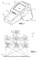
- FIG. 1 is a diagram illustrating a blood vessel locating device according to one embodiment.
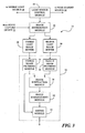
- FIG. 2 is a block diagram illustrating blood vessel locating circuitry according to one embodiment.
- FIG. 3 is a block diagram illustrating the control device shown in FIG. 2 according to one embodiment.
- FIG. 4 is a flow chart illustrating a method for locating blood vessels according to one embodiment.
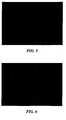
- FIG. 5 is an image of a portion of a subject's skin illuminated with light in the visible spectrum, according to one embodiment.
- FIG. 6 is an image of a portion of a subject's skin illuminated with light in the near IR spectrum, according to one embodiment.
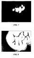
- FIG. 7 is a differential image processed by calculating a difference between the image of FIG. 5 and the image of FIG. 6 , according to one embodiment.
- FIG. 8 is an image processed by enhancing the differential image of FIG. 7 , according to one embodiment.
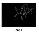
- FIG. 9 is an image processed by adding the enhanced image of FIG. 8 with the image of FIG. 5 , according to one embodiment.
- hemoglobin In the blood of humans and animals, hemoglobin carries oxygen from the lungs to other parts of the body. The oxygen is then released from the blood to the body tissues as needed, and the oxygen-depleted blood travels back to the lungs, where the blood is replenished with oxygen. During respiration, oxygen binds with the heme protein to form oxy-hemoglobin, which is the oxygen-loaded form of hemoglobin. When the oxygen is released, the deoxy-hemoglobin form is produced.
- Oxy-hemoglobin naturally contains specific light absorption and light reflection characteristics depending on the wavelength of light.
- Deoxy-hemoglobin also contains its own specific light absorption and reflectivity characteristics with respect to light wavelength. It is noted, however, that when light at a wavelength of approximately 880 nm is emitted, the light absorption and reflection characteristics of both oxy-hemoglobin and deoxy-hemoglobin are about the same. At this wavelength, though, light does not experience absorption but experiences either transmission or reflection from other body tissue, such as the tissue in the vicinity of the blood vessels. Light that is transmitted through some layers of tissue is reflected by deeper tissue. The reflection characteristics of body tissue at 880 nm are about the same as its reflection characteristics under regular light in the visible spectrum.
- the tissue By illuminating the skin with infrared light at approximately 880 nm, the tissue will normally reflect the light, while the blood vessels, containing either oxy-hemoglobin or deoxy-hemoglobin, absorb the light, thereby making the location of the blood vessels appear darker. Since 880 nm is in the infrared range, it cannot be seen by the human eye. However, many image sensors, such as charge coupled devices (CCDs) or complementary metal-oxide semiconductor (CMOS) imaging devices, are responsive to infrared light. Thus, the procedure of illuminating skin with infrared light can be used to make the blood vessels visually stand out with respect to the surrounding tissue.
- CCDs charge coupled devices
- CMOS complementary metal-oxide semiconductor
- an infrared light is emitted onto the skin and an image of the skin is taken.
- This image taken under the infrared light slightly distinguishes the blood vessels from the surrounding tissues.
- Imaging techniques such as contrast enhancement, brightness leveling, and edge sharpening, may be used to optimize this image for subsequent processing.
- a second image is captured using light within the visible light spectrum.
- the visible light may be in the blue-green region, for example, and may have a wavelength of approximately 470 nm. Since light in the visible spectrum, particularly bluish light, tends to be reflected by tissue and blood vessels, the visibility of the blood vessels in an image captured under this light is greatly reduced.
- This second image may also be optimized for subsequent processing, such as by smoothing or blurring to remove skin surface features that may be more apparent under the visible light.
- visible light Although the terms “visible light”, “visible spectrum”, etc. are used throughout the present disclosure, it should be noted that the type or frequency range of these lights may actually include any suitable wavelength or range that is different from the infrared light spectrum and does not necessarily require light that is visible to humans. However, for the sake of simplicity and consistency, the terms visible light, visible spectrum, etc. are used herein.
- an image processing device of the present disclosure subtracts one image from the other to obtain a differential image, which tends to highlight the location of the blood vessels and substantially eliminate the image of the skin and tissues.
- This differential image is then enhanced to make the image even more distinctive.
- one enhancement technique may include colorizing the differential image. After enhancement of the differential image, the enhanced image is added to the original image captured under regular or visible light. The resulting image is therefore an even greater representation of the location of blood vessels. Knowing the location of blood vessels, a medical professional is better able to access the blood vessels to draw blood, insert an IV, insert a catheter, etc.
- FIG. 1 is a diagram illustrating an embodiment of a blood vessel locating device 10.
- blood vessel locating device 10 includes a housing 12 that supports electrical circuitry therein (not shown in FIG. 1 ).
- a portion of housing 12 includes a handle 14 allowing blood vessel locating device 10 to be held within a user's hand. In this sense, blood vessel locating device 10 is easily transportable and easy to manipulate.
- Blood vessel locating device 10 also includes an open-ended enclosure 16, which in this implementation includes a circular cross-section forming a cylindrical tube.
- enclosure 16 may have any reasonable shape or cross-section and may be located in other positions and orientations relative to handle 14.
- enclosure 16 contains light sources, which can be supported along the interior surface of enclosure 16.
- At least a first set of light sources in enclosure 16 is capable of emitting light having a shorter wavelength than infrared light, such as light within a spectrum that is normally visible to a human eye.
- a second set of light sources is capable of emitting light within a near infrared (near IR) spectrum, which includes a wavelength range from 700 nm to 1.4 ⁇ m.
- Enclosure 16 may include one or more diffusing mechanisms configured to diffuse the light from the light sources in order to eliminate bright spots and to create a substantially uniform illumination pattern on the skin.
- enclosure 16 Also residing within enclosure 16 is an image capture device, such as, for example, a camera, one or more CCDs or CMOS devices, or other suitable device for detecting an image. Enclosure 16 may serve to maintain a minimum distance from the image capture device to the skin to accommodate the focal length of the image capture device. Enclosure 16 also serves to reduce the ambient light from external light sources. In addition to the embodiment of FIG. 1 , housing 12 and enclosure 16 may include any design or configuration as desired. For example, blood vessel locating device 10 may be configured as a pocket scanner, a pen-shaped detecting device, etc.
- Blood vessel locating device 10 also includes input devices 18 and a display screen 20.
- input devices 18 are shown as toggle switches, but in other embodiment, input devices 18 may include other suitable types of data entry or selection devices as well.
- input devices 18 may function to allow a user to enter information regarding the wavelength of light that is emitted from the light sources.
- the four switches shown in FIG. 1 may include, for example, one switch for selecting white light, one for selecting blue light, one for red light, and another for infrared.
- Input devices 18 may also allow entry of other information and/or selections as needed.
- Display screen 20 is configured to display a final image, as described in more detail below, representing the location of blood vessels. Images shown on display screen 20 are presented in real time or after a reasonably short delay. Images can be processed and displayed at about 30 frames per second or at any other suitable rate.
- blood vessel locating device 10 is placed near a portion of a subject's skin where embedded blood vessels are to be located.
- the subject may be a human patient in a clinical or medical setting. In other embodiments, the subject may be an animal or pet under the care of a veterinarian. For proper operation in a veterinary setting, modifications to blood vessel locating device 10 may be made if necessary.
- Blood vessel locating device 10 is held such that the open end of enclosure 16 is directed toward the section of the subject's skin that is to be observed.
- a small stand may be used in conjunction with or incorporated with blood vessel locating device 10 such that the user can access the skin while blood vessel locating device 10 is positioned a short distance from the skin.
- blood vessel locating device 10 emits a first light in the visible spectrum and captures a first image of the skin when illuminated with the first light. Blood vessel locating device 10 also emits a second light in the near IR spectrum and captures a second image of the skin when illuminated with the second light. It should be noted that the order of illumination of the different lights can be reversed.
- Processing circuitry within blood vessel locating device 10 processes the images individually and then obtains a differential image by calculating the difference between the first image associated with the visible light and the second image associated with the near IR light. This differential image is then enhanced, such as by colorizing the image, increasing the contrast of the image, darkening the image, and/or other suitable enhancement procedures. The processing circuitry then superimposes the enhanced image on the first image, which is associated with the visible light, to obtain a final image. This final image is then displayed on display screen 20. It should be understood that the operation of blood vessel locating device 10 can include any order of steps and may differ from the sequence discussed above. For instance, emission of the two different lights can occur in the reverse order. Also, the order of the image processing actions involving individual processing, calculating differences, subtraction, enhancement, and superimposing can be altered depending on the particular design.
- FIG. 2 is a block diagram illustrating an embodiment of blood vessel locating circuitry 24.
- Blood vessel locating circuitry 24 can be associated with or incorporated within blood vessel locating device 10 of FIG. 1 or other device for locating blood vessels embedded under a portion of skin 26 of a subject or patient.
- blood vessel locating circuitry 24 includes a visible light source 28, near IR light source 30, image capture device 32, control device 34, input devices 36, output devices 38, and power source 40.
- Visible light source 28 is adapted to provide light to illuminate a portion of skin 26 of the subject.
- the light emitted from visible light source 28 is contained within a wavelength spectrum encompassing light waves that are visible to the human eye.
- the visible light spectrum may include wavelengths ranging from 380 nm to 750 nm.
- visible light source 28 comprises one or more light emitting diodes (LEDs) capable of emitting light within a narrow wavelength range. Some LEDs, for instance, can be categorized as having a single wavelength, such as 470 nm for emitting a bluish colored light, 660 nm for emitting a reddish colored light, etc.
- visible light source 28 comprises one or more incandescent bulbs that are capable of providing white light making up a wide spectrum of frequencies.
- Visible light source 28 may include any suitable number and any suitable type of device or devices for emitting light in the visible spectrum.
- Near IR light source 30 is adapted to provide light to illuminate substantially the same portion of skin 26 of the subject that is illuminated by visible light source 26.
- the light emitted from near IR light source 30 is contained within a wavelength spectrum encompassing light waves in the near IR range, which includes infrared light from 700 nm to 1.4 ⁇ m.
- near IR light source 30 may be configured using one or more LEDs capable of emitting a light having a narrow wavelength band within the near IR range.
- near IR light source 30 may be LEDs configured to emit 880 nm infrared light.
- near IR light source 30 may include one or more devices that emit a wide spectrum of frequencies within the near IR range.
- Image capture device 32 is arranged in an orientation that allow it to capture at least an area of skin 26 illuminated by the two light sources.
- Image capture device 32 may include a digital camera, digital video camera, array of CCDs, CMOS devices, or other suitable devices for capturing images of skin 26.
- image capture device 32 may include one or more lenses, filters, etc., as needed.
- Control device 34 manages when visible light source 28 emits light and when near IR light source 30 emits light.
- control device 34 may cause visible light source 28 and near IR light source 30 to turn on at alternating times.
- skin 26 is illuminated with visible light for a first time period, illuminated with near IR light for a second time period, illuminated with visible light for a third time period, and so on.
- Control device 34 is further configured to instruct image capture device 32 to capture images of the same portion of skin 26 during the first time period, second time period, third time period, etc., to synchronize the light emission times with the image capturing times.
- the rate at which the light sources alternate correlates to the number of frames per second that are processed and displayed, which may be based on the processing speed of control device 34 and/or a time required for the light sources to reach a steady or predictable illumination state from an off state.
- Images from image capture device 32 are transmitted to control device 34, which then processes the images to locate blood vessels. Particularly, control device 34 individually filters the two different images to prepare the image for further processing. Control device 34 obtains a differential image showing the difference between the two images and then enhances the differential image. The enhanced image is then superimposed on one of the images for display on output device 38.
- Control device 34 may be a general-purpose or specific-purpose processor or microcontroller. Control device 34 may be associated with memory, which can include internally fixed storage and/or removable storage media for storing information, data, and/or instructions. Memory can also store one or more software programs that enable control device 34 to execute blood vessel locating programs and procedures as discussed in the present disclosure.
- Various logical instructions or commands may be included in the one or more software programs for locating blood vessels.
- the blood vessel locating programs executed by control device 34 can be implemented in hardware, software, firmware, or a combination thereof. When implemented in software or firmware, the programs can be stored in the memory and executed by control device 34.
- Blood vessel locating programs or software and any other programs or software code including executable logical instructions as described herein can be embodied in any suitable computer-readable medium for execution by any suitable processing device.
- the computer-readable medium can include any physical medium that can store the programs or software code for a measurable length of time.
- the blood vessel locating programs can be implemented, for example, using discrete logic circuitry, an application specific integrated circuit (ASIC), a programmable gate array (PGA), a field programmable gate array (FPGA), etc., or any combination thereof.
- ASIC application specific integrated circuit
- PGA programmable gate array
- FPGA field programmable gate array
- Input devices 36 may include any combination of keys, keypads, cursor control devices, switches, buttons, touch screen sensing mechanisms, etc., and/or may include any other suitable mechanisms allowing a user to enter data, instructions, information, etc.
- Output devices 38 may include any combination of display screens, such as display screen 20, indicator lights, audio mechanisms, etc., and/or may include any other suitable mechanisms for communicating information to the user.
- Input devices 36 and/or output devices 38 may be on the same physical device as image capture device 32 or alternatively may be separate, as desired.
- Power source 40 may include any suitable type of battery or batteries, battery related circuitry, rechargeable batteries, regulators, AC adapters, etc., and/or may include any other suitable device for providing electrical power to the components of blood vessel locating circuitry 24.
- FIG. 3 is a block diagram illustrating an embodiment of control device 34 shown in FIG. 2 .
- control device 34 includes a light source control module 44, image distribution module 46, visible light image buffer 48, near IR light image buffer 50, and image processing module 52.
- Image processing module 52 includes a visible image filtering module 54, a near IR image filtering module 56, an image subtraction module 58, an image enhancement module 60, and a mixing module 62.
- the elements of control device 34 may be embodied in software and/or hardware.
- Light source control module 44 may be configured to receive user inputs regarding information with respect to light source usage and times and other input for adjusting timing or clocking characteristics. Based on a predetermined or adjusted timing control pattern, light source control module 44 sends a signal to visible light source 28 as an instruction to emit light for a first period of time. Light source control module 44 also sends another signal to near IR light source 30 as an instruction to emit light for a second period of time. In some embodiments, the first and second periods of time can be the same, but in alternative embodiment, the time periods may be different if desired. These or other output signals from light source control module 44 are also sent to image capture device 32 as instructions to capture images of a portion of a subject's skin when illuminated by visible light source 28 or near IR light source 30. Light source control module 44 sends the signals to the light sources and image capture device 32 to coordinate or synchronize the illumination characteristics with the image capturing functions of image capture device 32. Thus, images of the subject's skin can be adequately obtained when illuminated by the two different light emissions.
- Image distribution module 46 is configured to receive images that are captured by image capture device 32. When an image is captured during the time that the subject's skin is illuminated with visible light, image distribution module 46 stores the image in visible light image buffer 48. On the other hand, when an image is captured during the time that the subject's skin is illuminated with near IR light, image distribution module 46 stores the image in near IR light image buffer 50. Buffers 48 and 50 may be configured to store a single image at a time. Therefore, a new image to be stored in a respective buffer replaces or writes over an old image. In other embodiments, buffers 48 and 50 may be configured to stored more than one image. With at least one image in each buffer 48 and 50, image processing module 52 can retrieve the latest images from the two buffers in order to process them according to the image processing description herein.
- Image processing module 52 includes visible image filtering module 54, which receives an image from visible light image buffer 48.
- Visible image filtering module 54 filters the visible image using any suitable filtering or processing techniques to prepare the visible image for further processing.
- the visible image can be processed to more clearly show features of the subject's skin that may not be as noticeable under other lights. Filtering may include smoothing effects to reduce the view of certain features of the skin, such as hair, freckles, changes in skin pigmentation, etc., the images of which are not necessarily needed for processing so as to help determine blood vessel location.
- Near IR filtering module 56 receives an image from near IR light image buffer 50 and filters the image using any suitable filtering or processing techniques to prepare the near IR image for further processing. Filtering in this respect may include enhancing contrast, altering brightness levels, sharpening the edges of the image, etc. Near IR image may be processed to more clearly show features that may not be as apparent under other lights and/or to reduce the view of certain features that are not necessarily needed for processing so as to help determine blood vessel location.
- Image subtraction module 58 receives image data relating to a first image from visible image filtering module 54 and simultaneously receives image data relating to a second image from near IR image filtering module 56. Image subtraction module 58 then calculates the differences between the two images, captured at approximately the same time, where each image represents illumination by one of the two sources of different lights. The differences between the two images can be calculated, for example, by subtracting the pixel values of the visible light image from the pixel values of the near IR light image. In other embodiments, image subtraction module 58 may subtract the near IR light image from the visible light image. The resulting image calculated by the difference between the two images is referred to herein as a differential image.
- Image enhancement module 60 receives the differential image from image subtraction module 58 and enhances the differential image. Enhancement in this respect may include any suitable processing algorithms or procedures to more greatly distinguish the differences between the two original images.
- image enhancement module 60 may comprise a colorization procedure to add colors, such as brighter or more noticeable colors, to the differential image.
- Other examples of enhancement may include adjusting the contrast or brightness of the image. These and other procedures may be run to enhance the differential image.
- the enhanced image is then sent to mixing module 62.
- Mixing module 62 combines the enhanced image with the visible light image from visible light image buffer 48. Mixing module 62 combines the images by superimposing one image on the other, using a mixing algorithm, or using any other suitable image combining procedures. At its output, mixing module 62 can provide the final image to an output device, such as, for instance, display screen 20.
- FIG. 4 is a flow chart showing an embodiment of a method for locating blood vessels.
- a first image of a subject's or patient's skin is captured.
- the image is captured when the skin is illuminated with light having at least one wavelength in the visible light spectrum.
- a second image of the subject's skin is captured.
- the capture image in this case is associated with the condition that the skin is illuminated with a light emission within the near IR spectrum.
- the image capture procedures of blocks 70 and 72 may further be associated with procedures for storing the images as needed.
- blocks 70 and 72 may be reversed such that when a current near IR light illuminated image is already stored, the next image to be captured may be a visible light illuminated image.
- each of the first and second images is individually filtered. Filtering may include any suitable procedure or procedures for enhancing or reducing certain features of the images.
- a difference is calculated between the first image associated with visible light illumination and the second image associated with near IR light illumination, as indicated in block 76. This subtraction process is performed in order to obtain a differential image.
- the differential image is enhanced using any suitable enhancement technique.
- the enhanced image is added or mixed with the first image associated with visible light illumination to obtain a final image showing an enhanced view of the location of blood vessels.
- steps, processes, or operations described herein may represent any module or code sequence that can be implemented in software or firmware.
- these modules and code sequences can include commands or instructions for executing specific logical steps, processes, or operations within physical components.
- one or more of the steps, processes, and/or operations described herein may be executed substantially simultaneously or in a different order than explicitly described, as would be understood by one of ordinary skill in the art.
- FIGS. 5-8 show examples of captured images of a portion of a subject's skin.
- FIG. 5 shows an image of the subject's skin when illuminated with light emission in the visible light spectrum.
- FIG. 6 shows an image of the subject's skin when illuminated with light emission in the near IR light spectrum. From these two captured images, image processing techniques are used to enhance an image that can be displayed for the user to see.
- FIG. 7 shows a differential image calculated from the difference between the images of FIGS. 5 and 6 . In some embodiments, one image, such as the visible light image, is subtracted from the other image, such as the near IR light image. The differential image of FIG. 7 is enhanced to more clearly distinguish the blood vessels from surrounding tissue. The enhanced image is illustrated in FIG. 8 .
- FIG. 8 shows an image of the blood vessels from surrounding tissue.
- FIG. 9 shows the final image when the enhanced differential image is added back with the visible light image.
- This final image can be displayed on a display screen for clearly showing the location of blood vessels embedded under the skin.
Landscapes
- Health & Medical Sciences (AREA)
- Life Sciences & Earth Sciences (AREA)
- Heart & Thoracic Surgery (AREA)
- Medical Informatics (AREA)
- Biophysics (AREA)
- Pathology (AREA)
- Engineering & Computer Science (AREA)
- Biomedical Technology (AREA)
- Veterinary Medicine (AREA)
- Physics & Mathematics (AREA)
- Molecular Biology (AREA)
- Surgery (AREA)
- Animal Behavior & Ethology (AREA)
- General Health & Medical Sciences (AREA)
- Public Health (AREA)
- Vascular Medicine (AREA)
- Measuring And Recording Apparatus For Diagnosis (AREA)
- Measurement Of The Respiration, Hearing Ability, Form, And Blood Characteristics Of Living Organisms (AREA)
Applications Claiming Priority (2)
| Application Number | Priority Date | Filing Date | Title |
|---|---|---|---|
| US12/059,132 US7792334B2 (en) | 2008-03-31 | 2008-03-31 | Locating blood vessels |
| PCT/US2009/000975 WO2009123670A1 (en) | 2008-03-31 | 2009-02-17 | Locating blood vessels |
Publications (2)
| Publication Number | Publication Date |
|---|---|
| EP2259718A1 EP2259718A1 (en) | 2010-12-15 |
| EP2259718B1 true EP2259718B1 (en) | 2013-10-16 |
Family
ID=40580630
Family Applications (1)
| Application Number | Title | Priority Date | Filing Date |
|---|---|---|---|
| EP09727440.1A Not-in-force EP2259718B1 (en) | 2008-03-31 | 2009-02-17 | Locating blood vessels |
Country Status (4)
| Country | Link |
|---|---|
| US (1) | US7792334B2 (enExample) |
| EP (1) | EP2259718B1 (enExample) |
| JP (1) | JP5528425B2 (enExample) |
| WO (1) | WO2009123670A1 (enExample) |
Families Citing this family (93)
| Publication number | Priority date | Publication date | Assignee | Title |
|---|---|---|---|---|
| WO2007009063A2 (en) | 2005-07-13 | 2007-01-18 | Branch Thomas P | Apparatus and method for evaluating ligaments |
| US8478386B2 (en) | 2006-01-10 | 2013-07-02 | Accuvein Inc. | Practitioner-mounted micro vein enhancer |
| US10238294B2 (en) | 2006-06-29 | 2019-03-26 | Accuvein, Inc. | Scanned laser vein contrast enhancer using one laser |
| US11253198B2 (en) | 2006-01-10 | 2022-02-22 | Accuvein, Inc. | Stand-mounted scanned laser vein contrast enhancer |
| US9854977B2 (en) | 2006-01-10 | 2018-01-02 | Accuvein, Inc. | Scanned laser vein contrast enhancer using a single laser, and modulation circuitry |
| US8489178B2 (en) | 2006-06-29 | 2013-07-16 | Accuvein Inc. | Enhanced laser vein contrast enhancer with projection of analyzed vein data |
| US12471844B2 (en) | 2006-06-29 | 2025-11-18 | Accuvein, Inc. | Scanned laser vein contrast enhancer with full stopping of scanner movement during scan line reversals |
| US12089951B2 (en) | 2006-01-10 | 2024-09-17 | AccuVeiw, Inc. | Scanned laser vein contrast enhancer with scanning correlated to target distance |
| US12408865B2 (en) | 2006-01-10 | 2025-09-09 | Accuvein Inc. | Vein imaging device with differential image resolution at the center and the extremities of the vein image |
| US8838210B2 (en) * | 2006-06-29 | 2014-09-16 | AccuView, Inc. | Scanned laser vein contrast enhancer using a single laser |
| US12295744B2 (en) | 2006-01-10 | 2025-05-13 | Accuvein, Inc. | Micro vein enhancer with two lasers and two optical detectors configured for removing surface topology |
| US10813588B2 (en) | 2006-01-10 | 2020-10-27 | Accuvein, Inc. | Micro vein enhancer |
| US11278240B2 (en) | 2006-01-10 | 2022-03-22 | Accuvein, Inc. | Trigger-actuated laser vein contrast enhancer |
| US9492117B2 (en) | 2006-01-10 | 2016-11-15 | Accuvein, Inc. | Practitioner-mounted micro vein enhancer |
| US8594770B2 (en) | 2006-06-29 | 2013-11-26 | Accuvein, Inc. | Multispectral detection and presentation of an object's characteristics |
| US8730321B2 (en) | 2007-06-28 | 2014-05-20 | Accuvein, Inc. | Automatic alignment of a contrast enhancement system |
| US8463364B2 (en) | 2009-07-22 | 2013-06-11 | Accuvein Inc. | Vein scanner |
| US9968256B2 (en) | 2007-03-08 | 2018-05-15 | Sync-Rx Ltd. | Automatic identification of a tool |
| US9629571B2 (en) | 2007-03-08 | 2017-04-25 | Sync-Rx, Ltd. | Co-use of endoluminal data and extraluminal imaging |
| US9305334B2 (en) | 2007-03-08 | 2016-04-05 | Sync-Rx, Ltd. | Luminal background cleaning |
| US10716528B2 (en) | 2007-03-08 | 2020-07-21 | Sync-Rx, Ltd. | Automatic display of previously-acquired endoluminal images |
| US11064964B2 (en) | 2007-03-08 | 2021-07-20 | Sync-Rx, Ltd | Determining a characteristic of a lumen by measuring velocity of a contrast agent |
| JP5639764B2 (ja) | 2007-03-08 | 2014-12-10 | シンク−アールエックス,リミティド | 運動する器官と共に使用するイメージング及びツール |
| US8781193B2 (en) | 2007-03-08 | 2014-07-15 | Sync-Rx, Ltd. | Automatic quantitative vessel analysis |
| US11197651B2 (en) | 2007-03-08 | 2021-12-14 | Sync-Rx, Ltd. | Identification and presentation of device-to-vessel relative motion |
| US9375164B2 (en) | 2007-03-08 | 2016-06-28 | Sync-Rx, Ltd. | Co-use of endoluminal data and extraluminal imaging |
| US7995816B2 (en) * | 2007-09-24 | 2011-08-09 | Baxter International Inc. | Detecting access disconnect by pattern recognition |
| CA2711620A1 (en) | 2008-01-08 | 2009-07-16 | Bluesky Medical Group Inc. | Sustained variable negative pressure wound treatment and method of controlling same |
| EP2257320A2 (en) | 2008-03-12 | 2010-12-08 | Bluesky Medical Group Inc. | Negative pressure dressing and method of using same |
| US9107697B2 (en) * | 2008-06-04 | 2015-08-18 | Restoration Robotics, Inc. | System and method for selecting follicular units for harvesting |
| US8652186B2 (en) * | 2008-06-04 | 2014-02-18 | Restoration Robotics, Inc. | System and method for selecting follicular units for harvesting |
| US20110301500A1 (en) | 2008-10-29 | 2011-12-08 | Tim Maguire | Automated vessel puncture device using three-dimensional(3d) near infrared (nir) imaging and a robotically driven needle |
| US10362962B2 (en) | 2008-11-18 | 2019-07-30 | Synx-Rx, Ltd. | Accounting for skipped imaging locations during movement of an endoluminal imaging probe |
| US9974509B2 (en) | 2008-11-18 | 2018-05-22 | Sync-Rx Ltd. | Image super enhancement |
| US11064903B2 (en) | 2008-11-18 | 2021-07-20 | Sync-Rx, Ltd | Apparatus and methods for mapping a sequence of images to a roadmap image |
| US9061109B2 (en) | 2009-07-22 | 2015-06-23 | Accuvein, Inc. | Vein scanner with user interface |
| WO2011116347A1 (en) * | 2010-03-19 | 2011-09-22 | Quickvein, Inc. | Apparatus and methods for imaging blood vessels |
| WO2012123869A2 (en) * | 2011-03-15 | 2012-09-20 | Koninklijke Philips Electronics N.V. | Device for optical nerve localization and optical nerve stimulation |
| JP6134789B2 (ja) | 2012-06-26 | 2017-05-24 | シンク−アールエックス,リミティド | 管腔器官における流れに関連する画像処理 |
| US9072426B2 (en) | 2012-08-02 | 2015-07-07 | AccuVein, Inc | Device for detecting and illuminating vasculature using an FPGA |
| US10517483B2 (en) | 2012-12-05 | 2019-12-31 | Accuvein, Inc. | System for detecting fluorescence and projecting a representative image |
| GB201317746D0 (en) | 2013-10-08 | 2013-11-20 | Smith & Nephew | PH indicator |
| US20190212311A1 (en) | 2013-01-11 | 2019-07-11 | Smith & Nephew Plc | Ph and moisture indicator devices and formulations |
| US8983157B2 (en) | 2013-03-13 | 2015-03-17 | Restoration Robotics, Inc. | System and method for determining the position of a hair tail on a body surface |
| WO2014160804A2 (en) | 2013-03-26 | 2014-10-02 | The Trustees Of Columbia University In The City Of New York | Fluid extraction and drug delivery system and methods using microneedles |
| CN203289635U (zh) | 2013-05-10 | 2013-11-13 | 瑞声声学科技(深圳)有限公司 | 弹簧板及应用该弹簧板的多功能发声器 |
| US10939869B2 (en) * | 2013-06-18 | 2021-03-09 | Lawrence Livermore National Security, Llc | Imaging system and method for enhanced visualization of near surface vascular structures |
| ITFI20130255A1 (it) * | 2013-10-23 | 2015-04-24 | Insono S R L | "dispositivo per la rilevazione non invasiva di predeterminate strutture biologiche" |
| US20170032523A1 (en) * | 2014-04-10 | 2017-02-02 | Sync-Rx, Ltd | Image Analysis in the Presence of a Medical Device |
| WO2015173821A1 (en) | 2014-05-14 | 2015-11-19 | Sync-Rx, Ltd. | Object identification |
| US9968285B2 (en) * | 2014-07-25 | 2018-05-15 | Christie Digital Systems Usa, Inc. | Multispectral medical imaging devices and methods thereof |
| US10613629B2 (en) | 2015-03-27 | 2020-04-07 | Chad Laurendeau | System and method for force feedback interface devices |
| US9830495B2 (en) * | 2015-07-17 | 2017-11-28 | Motorola Mobility Llc | Biometric authentication system with proximity sensor |
| JP6671946B2 (ja) * | 2015-12-11 | 2020-03-25 | キヤノン株式会社 | 情報取得装置、撮像装置及び情報取得方法 |
| CA3023772A1 (en) | 2016-05-13 | 2017-11-16 | Smith & Nephew Plc | Sensor enabled wound monitoring and therapy apparatus |
| EP3592230A1 (en) | 2017-03-09 | 2020-01-15 | Smith & Nephew PLC | Apparatus and method for imaging blood in a target region of tissue |
| EP3592219B1 (en) | 2017-03-09 | 2023-05-10 | Smith & Nephew plc | Device and apparatus of determining skin perfusion pressure |
| GB201703769D0 (en) * | 2017-03-09 | 2017-04-26 | Smith & Nephew | Imaging apparatus and method of imaging |
| US11690570B2 (en) | 2017-03-09 | 2023-07-04 | Smith & Nephew Plc | Wound dressing, patch member and method of sensing one or more wound parameters |
| US11883262B2 (en) | 2017-04-11 | 2024-01-30 | Smith & Nephew Plc | Component positioning and stress relief for sensor enabled wound dressings |
| US11791030B2 (en) | 2017-05-15 | 2023-10-17 | Smith & Nephew Plc | Wound analysis device and method |
| WO2018210693A1 (en) | 2017-05-15 | 2018-11-22 | Smith & Nephew Plc | Negative pressure wound therapy system using eulerian video magnification |
| JP7189159B2 (ja) | 2017-06-23 | 2022-12-13 | スミス アンド ネフュー ピーエルシー | センサを有効化した創傷モニタリングまたは治療のためのセンサの配置 |
| CN109247910B (zh) * | 2017-07-12 | 2020-12-15 | 京东方科技集团股份有限公司 | 血管显示设备以及血管显示方法 |
| GB201809007D0 (en) | 2018-06-01 | 2018-07-18 | Smith & Nephew | Restriction of sensor-monitored region for sensor-enabled wound dressings |
| GB201804502D0 (en) | 2018-03-21 | 2018-05-02 | Smith & Nephew | Biocompatible encapsulation and component stress relief for sensor enabled negative pressure wound therapy dressings |
| AU2018312883B2 (en) | 2017-08-10 | 2024-06-13 | Smith & Nephew Plc | Positioning of sensors for sensor enabled wound monitoring or therapy |
| GB201804971D0 (en) | 2018-03-28 | 2018-05-09 | Smith & Nephew | Electrostatic discharge protection for sensors in wound therapy |
| GB201718870D0 (en) | 2017-11-15 | 2017-12-27 | Smith & Nephew Inc | Sensor enabled wound therapy dressings and systems |
| JP7653254B2 (ja) | 2017-09-10 | 2025-03-28 | スミス アンド ネフュー ピーエルシー | 封入を検査するためのシステムおよび方法、ならびにセンサを装備した創傷被覆材内の構成要素 |
| GB201718859D0 (en) | 2017-11-15 | 2017-12-27 | Smith & Nephew | Sensor positioning for sensor enabled wound therapy dressings and systems |
| JP7282079B2 (ja) | 2017-09-27 | 2023-05-26 | スミス アンド ネフュー ピーエルシー | センサが使用可能な陰圧創傷監視および療法装置のph感知 |
| WO2019072531A1 (en) | 2017-09-28 | 2019-04-18 | Smith & Nephew Plc | NEUROSTIMULATION AND MONITORING USING A SENSOR ACTIVATED WOUND SURVEILLANCE AND TREATMENT APPARATUS |
| WO2019096828A1 (en) | 2017-11-15 | 2019-05-23 | Smith & Nephew Plc | Integrated sensor enabled wound monitoring and/or therapy dressings and systems |
| GB201814011D0 (en) | 2018-08-29 | 2018-10-10 | Smith & Nephew | Componet positioning and encapsulation for sensor enabled wound dressings |
| GB2592508B (en) | 2018-09-12 | 2022-08-31 | Smith & Nephew | Device, apparatus and method of determining skin perfusion pressure |
| EP3856104B1 (en) | 2018-09-28 | 2025-08-06 | T.J.Smith And Nephew, Limited | Optical fibers for optically sensing through wound dressings |
| GB201816838D0 (en) | 2018-10-16 | 2018-11-28 | Smith & Nephew | Systems and method for applying biocompatible encapsulation to sensor enabled wound monitoring and therapy dressings |
| CN111248855A (zh) * | 2018-11-30 | 2020-06-09 | 财团法人金属工业研究发展中心 | 光学显影装置以及光学显影方法 |
| GB201820927D0 (en) | 2018-12-21 | 2019-02-06 | Smith & Nephew | Wound therapy systems and methods with supercapacitors |
| WO2020157103A1 (en) | 2019-01-30 | 2020-08-06 | Smith & Nephew Plc | Sensor integrated dressings and systems |
| GB201901242D0 (en) | 2019-01-30 | 2019-03-20 | Smith & Nephew | Optical sensing systems and methods for sensing enabled wound dressings and systems |
| GB2597148B (en) | 2019-03-18 | 2022-12-21 | Smith & Nephew | Design rules for sensor integrated substrates |
| EP3941346B1 (en) | 2019-03-19 | 2026-05-06 | Smith & Nephew PLC | Systems and methods for measuring tissue impedance |
| GB201914443D0 (en) | 2019-10-07 | 2019-11-20 | Smith & Nephew | Sensor enabled negative pressure wound monitoring apparatus with different impedances inks |
| US12232869B2 (en) * | 2019-10-18 | 2025-02-25 | Viavi Solutions Inc. | Sensor device |
| EP3820138A1 (en) * | 2019-11-06 | 2021-05-12 | Koninklijke Philips N.V. | A system for performing image motion compensation |
| GB201918856D0 (en) | 2019-12-19 | 2020-02-05 | Smith & Nephew | Sensor integrated dressings and systems |
| GB202003203D0 (en) | 2020-03-05 | 2020-04-22 | Smith & Nephew | Sensor integrated dressings and systems |
| EP4139904A1 (en) | 2020-04-21 | 2023-03-01 | T.J. Smith and Nephew, Limited | Wound treatment management using augmented reality overlay |
| GB202007391D0 (en) | 2020-05-19 | 2020-07-01 | Smith & Nephew | Patient protection from unsafe electric current in sensor integrated dressings and systems |
| GB202103265D0 (en) * | 2021-03-09 | 2021-04-21 | Univ Oxford Innovation Ltd | Vascular imaging tool |
| US20230421679A1 (en) * | 2023-01-27 | 2023-12-28 | Apple Inc. | Handheld electronic device |
Citations (3)
| Publication number | Priority date | Publication date | Assignee | Title |
|---|---|---|---|---|
| US5787185A (en) * | 1993-04-01 | 1998-07-28 | British Technology Group Ltd. | Biometric identification of individuals by use of subcutaneous vein patterns |
| JP2006098340A (ja) * | 2004-09-30 | 2006-04-13 | Sharp Corp | 内部検出装置 |
| EP1834581A1 (en) * | 2004-11-15 | 2007-09-19 | NEC Corporation | Living body feature innput device |
Family Cites Families (15)
| Publication number | Priority date | Publication date | Assignee | Title |
|---|---|---|---|---|
| JP3664541B2 (ja) | 1996-04-30 | 2005-06-29 | 富士写真フイルム株式会社 | 蛍光診断装置 |
| JP3567651B2 (ja) * | 1996-11-06 | 2004-09-22 | 株式会社日立製作所 | 生体識別装置 |
| KR100259475B1 (ko) * | 1997-04-14 | 2000-06-15 | 최환수 | 정맥분포패턴을 이용한 개인식별방법 |
| US6353753B1 (en) | 1998-05-05 | 2002-03-05 | Stephen Thomas Flock | Optical imaging of deep anatomic structures |
| US6447460B1 (en) | 1998-12-09 | 2002-09-10 | Kci Licensing, Inc. | Method for automated exclusion of deep venous thrombosis |
| AU2001259435A1 (en) | 2000-05-03 | 2001-11-12 | Stephen T Flock | Optical imaging of subsurface anatomical structures and biomolecules |
| US20030018271A1 (en) | 2001-07-02 | 2003-01-23 | Kimble Allan Wayne | Simplified and lightweight system for enhanced visualization of subcutaneous hemoglobin-containing structures |
| US7158660B2 (en) * | 2002-05-08 | 2007-01-02 | Gee Jr James W | Method and apparatus for detecting structures of interest |
| JP4487183B2 (ja) * | 2004-04-01 | 2010-06-23 | ソニー株式会社 | 撮像装置及び情報処理システム |
| WO2006014334A2 (en) | 2004-07-06 | 2006-02-09 | Advanced Biophotonics, Inc. | Systems and methods for localizing vascular architecture, and evaluation and monitoring of functional behavior of same |
| US20060020212A1 (en) | 2004-07-26 | 2006-01-26 | Tianning Xu | Portable vein locating device |
| JP2006102360A (ja) * | 2004-10-08 | 2006-04-20 | Matsushita Electric Ind Co Ltd | 生体情報提示装置 |
| JP2007054483A (ja) * | 2005-08-26 | 2007-03-08 | Olympus Corp | 装着型顕微鏡システム |
| WO2007115570A1 (en) | 2006-04-07 | 2007-10-18 | Novarix Ltd | Vein navigation device |
| WO2008010604A1 (en) * | 2006-07-19 | 2008-01-24 | School Juridical Person Kitasato Gakuen | Blood vessel imaging device and system for analyzing blood vessel distribution |
-
2008
- 2008-03-31 US US12/059,132 patent/US7792334B2/en not_active Expired - Fee Related
-
2009
- 2009-02-17 JP JP2011502930A patent/JP5528425B2/ja not_active Expired - Fee Related
- 2009-02-17 EP EP09727440.1A patent/EP2259718B1/en not_active Not-in-force
- 2009-02-17 WO PCT/US2009/000975 patent/WO2009123670A1/en not_active Ceased
Patent Citations (3)
| Publication number | Priority date | Publication date | Assignee | Title |
|---|---|---|---|---|
| US5787185A (en) * | 1993-04-01 | 1998-07-28 | British Technology Group Ltd. | Biometric identification of individuals by use of subcutaneous vein patterns |
| JP2006098340A (ja) * | 2004-09-30 | 2006-04-13 | Sharp Corp | 内部検出装置 |
| EP1834581A1 (en) * | 2004-11-15 | 2007-09-19 | NEC Corporation | Living body feature innput device |
Also Published As
| Publication number | Publication date |
|---|---|
| JP5528425B2 (ja) | 2014-06-25 |
| EP2259718A1 (en) | 2010-12-15 |
| WO2009123670A1 (en) | 2009-10-08 |
| JP2011516151A (ja) | 2011-05-26 |
| US20090245601A1 (en) | 2009-10-01 |
| US7792334B2 (en) | 2010-09-07 |
Similar Documents
| Publication | Publication Date | Title |
|---|---|---|
| EP2259718B1 (en) | Locating blood vessels | |
| US8996086B2 (en) | Digital mapping system and method | |
| JP5634755B2 (ja) | 電子内視鏡システム、電子内視鏡用のプロセッサ装置、及び電子内視鏡システムの作動方法 | |
| JP7135082B2 (ja) | 内視鏡装置、内視鏡装置の作動方法、及びプログラム | |
| JP6581984B2 (ja) | 内視鏡システム | |
| JP5914496B2 (ja) | 内視鏡システム及びプロセッサ装置並びに内視鏡システムの作動方法 | |
| JP7337073B2 (ja) | 医用画像処理装置及び内視鏡システム並びに医用画像処理装置の作動方法 | |
| JP7374280B2 (ja) | 内視鏡装置、内視鏡プロセッサ、及び内視鏡装置の作動方法 | |
| CN112584741B (zh) | 医疗图像处理系统 | |
| US20150272422A1 (en) | Endoscope system, processor device, and method for operating endoscope system | |
| JP2017158670A (ja) | 血管情報取得装置、内視鏡システム及び血管情報取得方法 | |
| CN112752535B (zh) | 医用图像处理装置和内窥镜系统以及医用图像处理装置的工作方法 | |
| WO2015049962A1 (ja) | 内視鏡システム | |
| JPWO2013035531A1 (ja) | 内視鏡システム及びその作動方法 | |
| CN112584742B (zh) | 医疗图像处理系统 | |
| CN105748029A (zh) | 一种内窥镜成像系统 | |
| JP2022179746A (ja) | 医療用制御装置、医療用観察システム、制御装置及び観察システム | |
| JP7335399B2 (ja) | 医用画像処理装置及び内視鏡システム並びに医用画像処理装置の作動方法 | |
| JPWO2019092948A1 (ja) | 内視鏡システム、内視鏡画像の生成方法及びプロセッサ | |
| JPWO2019163540A1 (ja) | 内視鏡システム | |
| JP5809850B2 (ja) | 画像処理装置 | |
| CN115361898A (zh) | 医疗图像处理装置、内窥镜系统及医疗图像处理装置的工作方法、以及医疗图像处理装置用程序 | |
| JP7130043B2 (ja) | 医用画像処理装置及び内視鏡システム並びに医用画像処理装置の作動方法 | |
| EP4445827A1 (en) | Processor device, operation method therefor, and endoscope system | |
| JP2003126015A (ja) | 内視鏡装置 |
Legal Events
| Date | Code | Title | Description |
|---|---|---|---|
| PUAI | Public reference made under article 153(3) epc to a published international application that has entered the european phase |
Free format text: ORIGINAL CODE: 0009012 |
|
| 17P | Request for examination filed |
Effective date: 20101008 |
|
| AK | Designated contracting states |
Kind code of ref document: A1 Designated state(s): AT BE BG CH CY CZ DE DK EE ES FI FR GB GR HR HU IE IS IT LI LT LU LV MC MK MT NL NO PL PT RO SE SI SK TR |
|
| AX | Request for extension of the european patent |
Extension state: AL BA RS |
|
| DAX | Request for extension of the european patent (deleted) | ||
| 17Q | First examination report despatched |
Effective date: 20110729 |
|
| GRAP | Despatch of communication of intention to grant a patent |
Free format text: ORIGINAL CODE: EPIDOSNIGR1 |
|
| INTG | Intention to grant announced |
Effective date: 20130426 |
|
| GRAS | Grant fee paid |
Free format text: ORIGINAL CODE: EPIDOSNIGR3 |
|
| GRAA | (expected) grant |
Free format text: ORIGINAL CODE: 0009210 |
|
| RAP1 | Party data changed (applicant data changed or rights of an application transferred) |
Owner name: IMMERSION CORPORATION |
|
| AK | Designated contracting states |
Kind code of ref document: B1 Designated state(s): AT BE BG CH CY CZ DE DK EE ES FI FR GB GR HR HU IE IS IT LI LT LU LV MC MK MT NL NO PL PT RO SE SI SK TR |
|
| REG | Reference to a national code |
Ref country code: GB Ref legal event code: FG4D |
|
| REG | Reference to a national code |
Ref country code: CH Ref legal event code: EP |
|
| REG | Reference to a national code |
Ref country code: IE Ref legal event code: FG4D |
|
| REG | Reference to a national code |
Ref country code: AT Ref legal event code: REF Ref document number: 636055 Country of ref document: AT Kind code of ref document: T Effective date: 20131115 |
|
| REG | Reference to a national code |
Ref country code: DE Ref legal event code: R096 Ref document number: 602009019476 Country of ref document: DE Effective date: 20131212 |
|
| REG | Reference to a national code |
Ref country code: NL Ref legal event code: VDEP Effective date: 20131016 |
|
| REG | Reference to a national code |
Ref country code: AT Ref legal event code: MK05 Ref document number: 636055 Country of ref document: AT Kind code of ref document: T Effective date: 20131016 |
|
| REG | Reference to a national code |
Ref country code: LT Ref legal event code: MG4D |
|
| PG25 | Lapsed in a contracting state [announced via postgrant information from national office to epo] |
Ref country code: IS Free format text: LAPSE BECAUSE OF FAILURE TO SUBMIT A TRANSLATION OF THE DESCRIPTION OR TO PAY THE FEE WITHIN THE PRESCRIBED TIME-LIMIT Effective date: 20140216 Ref country code: BE Free format text: LAPSE BECAUSE OF FAILURE TO SUBMIT A TRANSLATION OF THE DESCRIPTION OR TO PAY THE FEE WITHIN THE PRESCRIBED TIME-LIMIT Effective date: 20131016 Ref country code: FI Free format text: LAPSE BECAUSE OF FAILURE TO SUBMIT A TRANSLATION OF THE DESCRIPTION OR TO PAY THE FEE WITHIN THE PRESCRIBED TIME-LIMIT Effective date: 20131016 Ref country code: LT Free format text: LAPSE BECAUSE OF FAILURE TO SUBMIT A TRANSLATION OF THE DESCRIPTION OR TO PAY THE FEE WITHIN THE PRESCRIBED TIME-LIMIT Effective date: 20131016 Ref country code: SE Free format text: LAPSE BECAUSE OF FAILURE TO SUBMIT A TRANSLATION OF THE DESCRIPTION OR TO PAY THE FEE WITHIN THE PRESCRIBED TIME-LIMIT Effective date: 20131016 Ref country code: HR Free format text: LAPSE BECAUSE OF FAILURE TO SUBMIT A TRANSLATION OF THE DESCRIPTION OR TO PAY THE FEE WITHIN THE PRESCRIBED TIME-LIMIT Effective date: 20131016 Ref country code: NO Free format text: LAPSE BECAUSE OF FAILURE TO SUBMIT A TRANSLATION OF THE DESCRIPTION OR TO PAY THE FEE WITHIN THE PRESCRIBED TIME-LIMIT Effective date: 20140116 Ref country code: NL Free format text: LAPSE BECAUSE OF FAILURE TO SUBMIT A TRANSLATION OF THE DESCRIPTION OR TO PAY THE FEE WITHIN THE PRESCRIBED TIME-LIMIT Effective date: 20131016 |
|
| PG25 | Lapsed in a contracting state [announced via postgrant information from national office to epo] |
Ref country code: ES Free format text: LAPSE BECAUSE OF FAILURE TO SUBMIT A TRANSLATION OF THE DESCRIPTION OR TO PAY THE FEE WITHIN THE PRESCRIBED TIME-LIMIT Effective date: 20131016 Ref country code: CY Free format text: LAPSE BECAUSE OF FAILURE TO SUBMIT A TRANSLATION OF THE DESCRIPTION OR TO PAY THE FEE WITHIN THE PRESCRIBED TIME-LIMIT Effective date: 20131016 Ref country code: AT Free format text: LAPSE BECAUSE OF FAILURE TO SUBMIT A TRANSLATION OF THE DESCRIPTION OR TO PAY THE FEE WITHIN THE PRESCRIBED TIME-LIMIT Effective date: 20131016 Ref country code: LV Free format text: LAPSE BECAUSE OF FAILURE TO SUBMIT A TRANSLATION OF THE DESCRIPTION OR TO PAY THE FEE WITHIN THE PRESCRIBED TIME-LIMIT Effective date: 20131016 |
|
| PG25 | Lapsed in a contracting state [announced via postgrant information from national office to epo] |
Ref country code: PT Free format text: LAPSE BECAUSE OF FAILURE TO SUBMIT A TRANSLATION OF THE DESCRIPTION OR TO PAY THE FEE WITHIN THE PRESCRIBED TIME-LIMIT Effective date: 20140217 |
|
| REG | Reference to a national code |
Ref country code: DE Ref legal event code: R097 Ref document number: 602009019476 Country of ref document: DE |
|
| PG25 | Lapsed in a contracting state [announced via postgrant information from national office to epo] |
Ref country code: EE Free format text: LAPSE BECAUSE OF FAILURE TO SUBMIT A TRANSLATION OF THE DESCRIPTION OR TO PAY THE FEE WITHIN THE PRESCRIBED TIME-LIMIT Effective date: 20131016 |
|
| PLBE | No opposition filed within time limit |
Free format text: ORIGINAL CODE: 0009261 |
|
| STAA | Information on the status of an ep patent application or granted ep patent |
Free format text: STATUS: NO OPPOSITION FILED WITHIN TIME LIMIT |
|
| PG25 | Lapsed in a contracting state [announced via postgrant information from national office to epo] |
Ref country code: SK Free format text: LAPSE BECAUSE OF FAILURE TO SUBMIT A TRANSLATION OF THE DESCRIPTION OR TO PAY THE FEE WITHIN THE PRESCRIBED TIME-LIMIT Effective date: 20131016 Ref country code: RO Free format text: LAPSE BECAUSE OF FAILURE TO SUBMIT A TRANSLATION OF THE DESCRIPTION OR TO PAY THE FEE WITHIN THE PRESCRIBED TIME-LIMIT Effective date: 20131016 Ref country code: CZ Free format text: LAPSE BECAUSE OF FAILURE TO SUBMIT A TRANSLATION OF THE DESCRIPTION OR TO PAY THE FEE WITHIN THE PRESCRIBED TIME-LIMIT Effective date: 20131016 Ref country code: IT Free format text: LAPSE BECAUSE OF FAILURE TO SUBMIT A TRANSLATION OF THE DESCRIPTION OR TO PAY THE FEE WITHIN THE PRESCRIBED TIME-LIMIT Effective date: 20131016 Ref country code: PL Free format text: LAPSE BECAUSE OF FAILURE TO SUBMIT A TRANSLATION OF THE DESCRIPTION OR TO PAY THE FEE WITHIN THE PRESCRIBED TIME-LIMIT Effective date: 20131016 |
|
| 26N | No opposition filed |
Effective date: 20140717 |
|
| PG25 | Lapsed in a contracting state [announced via postgrant information from national office to epo] |
Ref country code: MC Free format text: LAPSE BECAUSE OF FAILURE TO SUBMIT A TRANSLATION OF THE DESCRIPTION OR TO PAY THE FEE WITHIN THE PRESCRIBED TIME-LIMIT Effective date: 20131016 Ref country code: LU Free format text: LAPSE BECAUSE OF FAILURE TO SUBMIT A TRANSLATION OF THE DESCRIPTION OR TO PAY THE FEE WITHIN THE PRESCRIBED TIME-LIMIT Effective date: 20140217 Ref country code: DK Free format text: LAPSE BECAUSE OF FAILURE TO SUBMIT A TRANSLATION OF THE DESCRIPTION OR TO PAY THE FEE WITHIN THE PRESCRIBED TIME-LIMIT Effective date: 20131016 |
|
| REG | Reference to a national code |
Ref country code: CH Ref legal event code: PL |
|
| REG | Reference to a national code |
Ref country code: DE Ref legal event code: R097 Ref document number: 602009019476 Country of ref document: DE Effective date: 20140717 |
|
| PG25 | Lapsed in a contracting state [announced via postgrant information from national office to epo] |
Ref country code: CH Free format text: LAPSE BECAUSE OF NON-PAYMENT OF DUE FEES Effective date: 20140228 Ref country code: LI Free format text: LAPSE BECAUSE OF NON-PAYMENT OF DUE FEES Effective date: 20140228 |
|
| REG | Reference to a national code |
Ref country code: IE Ref legal event code: MM4A |
|
| PG25 | Lapsed in a contracting state [announced via postgrant information from national office to epo] |
Ref country code: IE Free format text: LAPSE BECAUSE OF NON-PAYMENT OF DUE FEES Effective date: 20140217 |
|
| PG25 | Lapsed in a contracting state [announced via postgrant information from national office to epo] |
Ref country code: SI Free format text: LAPSE BECAUSE OF FAILURE TO SUBMIT A TRANSLATION OF THE DESCRIPTION OR TO PAY THE FEE WITHIN THE PRESCRIBED TIME-LIMIT Effective date: 20131016 |
|
| REG | Reference to a national code |
Ref country code: FR Ref legal event code: PLFP Year of fee payment: 8 |
|
| PG25 | Lapsed in a contracting state [announced via postgrant information from national office to epo] |
Ref country code: MT Free format text: LAPSE BECAUSE OF FAILURE TO SUBMIT A TRANSLATION OF THE DESCRIPTION OR TO PAY THE FEE WITHIN THE PRESCRIBED TIME-LIMIT Effective date: 20131016 |
|
| PG25 | Lapsed in a contracting state [announced via postgrant information from national office to epo] |
Ref country code: BG Free format text: LAPSE BECAUSE OF FAILURE TO SUBMIT A TRANSLATION OF THE DESCRIPTION OR TO PAY THE FEE WITHIN THE PRESCRIBED TIME-LIMIT Effective date: 20131016 |
|
| PG25 | Lapsed in a contracting state [announced via postgrant information from national office to epo] |
Ref country code: GR Free format text: LAPSE BECAUSE OF FAILURE TO SUBMIT A TRANSLATION OF THE DESCRIPTION OR TO PAY THE FEE WITHIN THE PRESCRIBED TIME-LIMIT Effective date: 20140117 |
|
| PG25 | Lapsed in a contracting state [announced via postgrant information from national office to epo] |
Ref country code: HU Free format text: LAPSE BECAUSE OF FAILURE TO SUBMIT A TRANSLATION OF THE DESCRIPTION OR TO PAY THE FEE WITHIN THE PRESCRIBED TIME-LIMIT; INVALID AB INITIO Effective date: 20090217 Ref country code: TR Free format text: LAPSE BECAUSE OF FAILURE TO SUBMIT A TRANSLATION OF THE DESCRIPTION OR TO PAY THE FEE WITHIN THE PRESCRIBED TIME-LIMIT Effective date: 20131016 |
|
| REG | Reference to a national code |
Ref country code: FR Ref legal event code: PLFP Year of fee payment: 9 |
|
| REG | Reference to a national code |
Ref country code: FR Ref legal event code: PLFP Year of fee payment: 10 |
|
| PG25 | Lapsed in a contracting state [announced via postgrant information from national office to epo] |
Ref country code: MK Free format text: LAPSE BECAUSE OF FAILURE TO SUBMIT A TRANSLATION OF THE DESCRIPTION OR TO PAY THE FEE WITHIN THE PRESCRIBED TIME-LIMIT Effective date: 20131016 |
|
| PGFP | Annual fee paid to national office [announced via postgrant information from national office to epo] |
Ref country code: GB Payment date: 20190227 Year of fee payment: 11 Ref country code: DE Payment date: 20190227 Year of fee payment: 11 |
|
| PGFP | Annual fee paid to national office [announced via postgrant information from national office to epo] |
Ref country code: FR Payment date: 20190225 Year of fee payment: 11 |
|
| REG | Reference to a national code |
Ref country code: DE Ref legal event code: R119 Ref document number: 602009019476 Country of ref document: DE |
|
| GBPC | Gb: european patent ceased through non-payment of renewal fee |
Effective date: 20200217 |
|
| PG25 | Lapsed in a contracting state [announced via postgrant information from national office to epo] |
Ref country code: DE Free format text: LAPSE BECAUSE OF NON-PAYMENT OF DUE FEES Effective date: 20200901 Ref country code: FR Free format text: LAPSE BECAUSE OF NON-PAYMENT OF DUE FEES Effective date: 20200229 Ref country code: GB Free format text: LAPSE BECAUSE OF NON-PAYMENT OF DUE FEES Effective date: 20200217 |