EP2258902A2 - Compacteur pouvant être connecté à un excavateur - Google Patents
Compacteur pouvant être connecté à un excavateur Download PDFInfo
- Publication number
- EP2258902A2 EP2258902A2 EP10180527A EP10180527A EP2258902A2 EP 2258902 A2 EP2258902 A2 EP 2258902A2 EP 10180527 A EP10180527 A EP 10180527A EP 10180527 A EP10180527 A EP 10180527A EP 2258902 A2 EP2258902 A2 EP 2258902A2
- Authority
- EP
- European Patent Office
- Prior art keywords
- compressor
- coupling
- compressor device
- excavator
- coupling device
- Prior art date
- Legal status (The legal status is an assumption and is not a legal conclusion. Google has not performed a legal analysis and makes no representation as to the accuracy of the status listed.)
- Withdrawn
Links
- 230000008878 coupling Effects 0.000 claims abstract description 36
- 238000010168 coupling process Methods 0.000 claims abstract description 36
- 238000005859 coupling reaction Methods 0.000 claims abstract description 36
- 239000000872 buffer Substances 0.000 claims abstract description 19
- 238000010521 absorption reaction Methods 0.000 claims abstract 2
- 230000006835 compression Effects 0.000 claims description 19
- 238000007906 compression Methods 0.000 claims description 19
- 239000002184 metal Substances 0.000 claims description 6
- 238000013016 damping Methods 0.000 claims description 5
- 239000012530 fluid Substances 0.000 claims description 5
- 238000005056 compaction Methods 0.000 description 12
- 230000003068 static effect Effects 0.000 description 12
- 239000002689 soil Substances 0.000 description 6
- 238000010276 construction Methods 0.000 description 5
- 230000000694 effects Effects 0.000 description 5
- 238000006073 displacement reaction Methods 0.000 description 2
- 238000005516 engineering process Methods 0.000 description 2
- 241001494479 Pecora Species 0.000 description 1
- 230000002730 additional effect Effects 0.000 description 1
- 230000003139 buffering effect Effects 0.000 description 1
- 238000007596 consolidation process Methods 0.000 description 1
- 238000007667 floating Methods 0.000 description 1
- 238000002955 isolation Methods 0.000 description 1
- 238000000034 method Methods 0.000 description 1
- 230000000704 physical effect Effects 0.000 description 1
- 239000011435 rock Substances 0.000 description 1
- 239000000725 suspension Substances 0.000 description 1
Images


Classifications
-
- E—FIXED CONSTRUCTIONS
- E02—HYDRAULIC ENGINEERING; FOUNDATIONS; SOIL SHIFTING
- E02D—FOUNDATIONS; EXCAVATIONS; EMBANKMENTS; UNDERGROUND OR UNDERWATER STRUCTURES
- E02D3/00—Improving or preserving soil or rock, e.g. preserving permafrost soil
- E02D3/02—Improving by compacting
- E02D3/046—Improving by compacting by tamping or vibrating, e.g. with auxiliary watering of the soil
- E02D3/074—Vibrating apparatus operating with systems involving rotary unbalanced masses
Definitions
- the invention relates to a compressor device according to the preamble of claim 1.
- Compressor devices use an unbalance generator for dynamic compression that drives a compactor plate.
- the unbalance generator is in the Usually driven by a hydraulic motor.
- Known compressor devices have a lower part and a upper part, between which damping devices, such as rubber-metal buffers, are arranged.
- the rubber-metal buffers are necessary to use the energy generated by the unbalance generator for compaction.
- they also serve to reduce the vibrations up to the excavator or the excavator. This usually does not succeed completely, so that vibrations are transmitted to the excavator at a coupled compressor device via the excavator, which have a negative effect on the life of bearings, bolts and the like.
- Compressor devices are coupled centrally in the prior art to the excavator. With a point compression, such a device can be controlled without problems. However, if the compactor device is pulled or pushed, the problem arises that the compactor device can not be guided.
- Coupled compressor devices are usually driven by the hydraulics of the excavator.
- Excavators that are suitable for use with compressor devices have only certain options for adjusting the amount of hydraulic. In general, the set hydraulic amount is much higher than actually required for driving the imbalance. As a result, disproportionately large hydraulic motors having a high displacement are used.
- the excavator must perform different functions simultaneously during compaction. In particular, the compressor device must be driven, the superstructure must be swiveled and the excavator handle and excavator arm must be moved. Due to these additional activities, the
- the drive of compressor devices is usually via the so-called "hammer line" of the excavator.
- a pre-pressure of approx. 150 to 250 l / min is generated with a working pressure of approx. 150 to 250 bar.
- the return line of this hammer line is fed directly to the hydraulic tank, which has a back pressure of max. 15 bar generated.
- standard gear pumps are used to drive the imbalance. Due to their design, they can only withstand a certain backpressure. Often, however, the hammer line is combined with a scissors line. In the "shear" function mode, the hydraulic direction can be mutually defined.
- Application examples are all attachments for an excavator that work in two directions, eg.
- Object of the present invention is therefore to develop a compressor device for an excavator such that the above-mentioned disadvantages are avoided.
- the axial piston motor or the gear motor generally has a small displacement. If instead of a standard gear hydraulic motor, an axial piston motor or a reinforced gear motor with leakage oil connection is used, the compressor device is used up to a back pressure of about 250 bar. This means that the excavator no longer needs to be switched from the "scissors" to the "hammer” mode when coupling a compressor unit.
- the Compressor device can be used in both modes of operation.
- a change system can be provided which simplifies the replacement of the compressor plates.
- different plate sizes can be easily attached to the compactor device.
- narrow trenches narrow plates can be mounted and for wide trenches wide plates can be mounted.
- different compressor plates can be used.
- slabs with a smooth surface can be replaced by slabs with a "sheep's foot”.
- Schaffußplatten have in cross-section trapezoidal blocks, which are for the compaction of, for example loamy soils of advantage. This means that at a construction site no longer different compressor devices, but only different compressor plates must be maintained.
- the first development provides for a storage-gentle additional buffering, in addition to the damping devices which are arranged between the upper part and the lower part or connect upper part and lower part with each other.
- the upper part has a Ankuppelabrough and a central portion, between which the at least one buffer means, in particular a plurality of rubber-metal buffers, is arranged.
- the at least one buffer means in particular a plurality of rubber-metal buffers.
- a coupling device may be provided, which is arranged off-center. This measure creates a caster, similar to a shopping cart.
- the compressor device can be better coordinated and guided. Another advantage is the longer reach when compacting.
- the compactor device can be introduced during compression under overhanging obstacles. This is particularly advantageous in exposed lines in sewer construction.
- the coupling device comprises a rotating device.
- the rotating device can be designed mechanically, in particular rotatable by 180 °, or hydraulically rotatable.
- a hydraulically rotatable rotary device an endless rotation can take place.
- the compressor device can be guided by the excavator to virtually any point.
- the coupling device is formed at least in one section, in particular axially, variable in length.
- the coupling device is telescopic.
- the coupling device further comprises an elastic pressure element, in particular a compression spring, which preferably acts between two telescopic sections.
- the compressor device be used both for static and for dynamic compression. In a floating position, ie with extended variable-length coupling device or relaxed compression spring, a dynamic compression can take place. Additional static pressure is not exerted by the excavator arm on the compactor device. However, when the excavator arm is moved down, the elastic pressure member is compressed, and the coupling device is shortened.
- a particularly fast connection of the compressor device to an excavator arm can take place if the coupling device comprises a coupling system, with which a mechanical and hydraulic connection to the excavator arm during coupling is produced simultaneously.
- This measure has the advantage that hydraulic connections do not have to be coupled separately.
- a flow control valve is used to control the amount of hydraulic fluid supplied to the axial piston motor or the reinforced gear motor with leakage oil connection.
- the superfluous hydraulic fluid can be discharged by the flow control valve controlled in front of the engine. Power fluctuations are compensated, and it is achieved a constant speed of the axial piston motor.
- the flow control valve is adjustable. By this measure, the speed for the imbalance can be adjusted.
- the physical properties of the soils to be compacted are very different.
- the speed of the unbalance therefore has a considerable influence on the compaction property.
- the speed can be easily adjusted.
- the same compressor device can be easily coupled to different excavators and operated at the same speed.
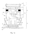
- Fig. 1a and 1b each show a compressor device 1, 30 in section, wherein like elements are provided with the same reference numerals.
- the compressor device 1, 30 comprises an upper part 2 and a lower part 3, wherein between the upper part 2 and the lower part 3 designed as a rubber-metal buffer damping means 4 are provided.
- an unbalance generator 5 is arranged, which sits on a plate 6, to which a removable system 7 is mounted on an exchangeable compressor plate 8.
- the unbalance generator 5 comprises an axial piston motor 9 or a geared motor, the hydraulic fluid controlled via an adjustable flow control valve 10 is supplied.
- the upper part 2 of the compressor device 1 is divided into an Ankuppelabites 11 and a central portion 12.
- the Ankuppelabites 11 and the central portion 12 are coupled via buffer means 13 which are formed as a rubber-metal buffer. Vibrations generated by the unbalance generator 5 are not or only slightly transmitted to the Ankuppelabites 11 by this measure.
- the coupling section 11 comprises a coupling system 14, with which a mechanical and hydraulic connection with an excavator arm can be made simultaneously.
- the coupling section 11 also has a turning device 15, so that the compressor plate 8 can be rotated relative to the coupling system 14.
- a suspension 31 is provided adjacent to the rotating device 15, which is connected via the buffer means 13 with one or more connecting parts 32.
- the connecting parts 32 have the buffer device 13 at their upper end and the damping devices 4 at their lower end. This two-stage vibration isolation protects the excavator against vibrations.
- the buffer means 13 are arranged outside the rotator 15.
- FIG. 2a a side view of the compressor device 1 is shown.
- an excavator arm 17 is shown, which is connected to the coupling system 14.
- the Fig. 1 is a sectional view taken along the line II of Fig. 2a , The section line II also represents the center line through the compactor device 1.
- the coupling device comprising the coupling system 14, the rotator 15 and the buffer devices 13 is arranged off-center. This means that the compressor device 1 can be pushed with its left half in the drawing under overhanging obstacles and can also compress below.
- the compressor plate 8 is in the Fig. 2a formed with a smooth bottom.
- FIG. 2b an alternative compressor plate 18 is shown, which has trapezoidal projections 19 on its underside in cross-section and is therefore particularly suitable for compacting loamy soils.
- the in the Fig. 2b shown compressor plate 18 can against the compressor plate 8 of Fig. 2a be replaced due to the change system.
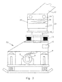
- a compactor device 20 In the Fig. 3 an alternative embodiment of a compactor device 20 is shown.
- an excavator arm 17 is also connected to the compressor device 20 via the hitching system 14.
- the coupling device 21 has a first telescopic section 22 and a second telescopic section 23, which are telescopic to each other.
- the coupling device is designed variable in length.
- an elastic pressure device 24 which is designed as a compression spring, is provided.
- the compression spring endeavors to push apart the telescopic parts 22, 23. If the compactor device 20 is not or only slightly acted upon by the excavator arm 17 with a force from above, the compacting device 20 acts essentially by its own weight on the soil to be compacted with a compaction force. This results in a dynamic compression. If the pressure element 24 is completely compressed, a static force is additionally exerted on the compressor device 20, resulting in a static compression.
Landscapes
- Engineering & Computer Science (AREA)
- Structural Engineering (AREA)
- Life Sciences & Earth Sciences (AREA)
- General Life Sciences & Earth Sciences (AREA)
- Soil Sciences (AREA)
- Environmental & Geological Engineering (AREA)
- Agronomy & Crop Science (AREA)
- Mining & Mineral Resources (AREA)
- Paleontology (AREA)
- Civil Engineering (AREA)
- General Engineering & Computer Science (AREA)
- Investigation Of Foundation Soil And Reinforcement Of Foundation Soil By Compacting Or Drainage (AREA)
- Earth Drilling (AREA)
- Shovels (AREA)
- Placing Or Removing Of Piles Or Sheet Piles, Or Accessories Thereof (AREA)
Applications Claiming Priority (2)
| Application Number | Priority Date | Filing Date | Title |
|---|---|---|---|
| DE10355172A DE10355172B3 (de) | 2003-11-26 | 2003-11-26 | Verdichtervorrichtung eines Baggers |
| EP04026634A EP1536068B1 (fr) | 2003-11-26 | 2004-11-10 | Compacteur pouvant être connecté à un excavateur |
Related Parent Applications (1)
| Application Number | Title | Priority Date | Filing Date |
|---|---|---|---|
| EP04026634.8 Division | 2004-11-10 |
Publications (2)
| Publication Number | Publication Date |
|---|---|
| EP2258902A2 true EP2258902A2 (fr) | 2010-12-08 |
| EP2258902A3 EP2258902A3 (fr) | 2011-11-09 |
Family
ID=34442291
Family Applications (2)
| Application Number | Title | Priority Date | Filing Date |
|---|---|---|---|
| EP10180527A Withdrawn EP2258902A3 (fr) | 2003-11-26 | 2004-11-10 | Compacteur pouvant être connecté à un excavateur |
| EP04026634A Expired - Lifetime EP1536068B1 (fr) | 2003-11-26 | 2004-11-10 | Compacteur pouvant être connecté à un excavateur |
Family Applications After (1)
| Application Number | Title | Priority Date | Filing Date |
|---|---|---|---|
| EP04026634A Expired - Lifetime EP1536068B1 (fr) | 2003-11-26 | 2004-11-10 | Compacteur pouvant être connecté à un excavateur |
Country Status (3)
| Country | Link |
|---|---|
| EP (2) | EP2258902A3 (fr) |
| AT (1) | ATE529572T1 (fr) |
| DE (1) | DE10355172B3 (fr) |
Cited By (4)
| Publication number | Priority date | Publication date | Assignee | Title |
|---|---|---|---|---|
| CN104261024A (zh) * | 2014-09-09 | 2015-01-07 | 衢州市依科达节能技术有限公司 | 一种垃圾收集挤压装袋机 |
| US9926677B1 (en) | 2016-09-26 | 2018-03-27 | Caterpillar Inc. | Constant down force vibratory compactor |
| US9945081B1 (en) | 2016-10-19 | 2018-04-17 | Caterpillar Inc. | Automatic shut-off for a vibratory plate compactor |
| DE102024119615A1 (de) * | 2024-07-10 | 2026-01-15 | Mts Schrode Ag | Anbauverdichter |
Families Citing this family (13)
| Publication number | Priority date | Publication date | Assignee | Title |
|---|---|---|---|---|
| US7805865B2 (en) | 2006-01-13 | 2010-10-05 | M-B-W, Inc. | Vibratory exciter unit for interchangeable connection to various vibratory tools |
| DE102006061398A1 (de) * | 2006-12-23 | 2008-06-26 | MTS Gesellschaft für Maschinentechnik und Sonderbauten mbH | Anbauverdichter |
| DE102008006211B4 (de) * | 2008-01-26 | 2012-11-29 | MTS Gesellschaft für Maschinentechnik und Sonderbauten mbH | Anbauverdichter |
| DE102008006889C5 (de) | 2008-01-31 | 2018-09-13 | Mts Maschinentechnik Schrode Ag | Verdichtervorrichtung |
| DE102008025026A1 (de) | 2008-05-24 | 2009-11-26 | MTS Gesellschaft für Maschinentechnik und Sonderbauten mbH | Bagger-Zusatzgerät |
| DE102009018490B4 (de) * | 2009-04-18 | 2015-05-28 | Mts Maschinentechnik Schrode Ag | Anbauverdichter, der an einen Bagger ankuppelbar ist, mit einem Unwuchterzeuger |
| DE102012200908B4 (de) * | 2012-01-23 | 2015-07-23 | Ammann Verdichtung Gmbh | Bodenverdichter und Verfahren zum Besohlen eines Bodenverdichters |
| DE102012210373A1 (de) | 2012-06-20 | 2013-12-24 | Mts Maschinentechnik Schrode Ag | Anbauverdichter |
| DE102013222122B4 (de) | 2013-10-30 | 2020-10-15 | Mts Maschinentechnik Schrode Ag | Verfahren zum Betreiben eines Bodenverdichtungs- oder Bodenprüfgeräts, sowie Bodenverdichtungs- oder Verdichtungsprüfgerät |
| DE102014011179A1 (de) * | 2014-07-31 | 2016-02-04 | Wacker Neuson Produktion GmbH & Co. KG | Bodenverdichtungsvorrichtung mit Abfederung und Führung |
| DE102016105872A1 (de) | 2016-03-31 | 2017-10-05 | Mts Maschinentechnik Schrode Ag | Verfahren zum Betreiben eines Anbauverdichters, sowie Speichermedium und Anbauverdichter |
| US9988770B1 (en) | 2016-12-02 | 2018-06-05 | Caterpillar Inc. | Impact wear plates for vibratory plate compactor |
| DE102018110465A1 (de) * | 2018-05-02 | 2019-11-07 | Mts Maschinentechnik Schrode Ag | Anbauwerkzeugeinrichtung |
Citations (2)
| Publication number | Priority date | Publication date | Assignee | Title |
|---|---|---|---|---|
| FR2415168A1 (fr) * | 1978-01-21 | 1979-08-17 | Weber Gunther | Plateau dameur vibrant a inversion de sens de marche |
| EP0220373A2 (fr) * | 1985-10-29 | 1987-05-06 | Hitachi Construction Machinery Co., Ltd. | Dispositif de compaction par vibration |
Family Cites Families (8)
| Publication number | Priority date | Publication date | Assignee | Title |
|---|---|---|---|---|
| AT34004B (de) * | 1907-05-22 | 1908-08-10 | Josef Winkowitsch | Schirmständer. |
| DE1264958B (de) * | 1960-10-08 | 1968-03-28 | Bosch Gmbh Robert | Zahnradpumpe oder -motor |
| DE3611191A1 (de) * | 1986-04-03 | 1987-10-15 | Kaeppeler Hans Joerg | Vorrichtung zum bodenverdichten |
| DE3827365A1 (de) * | 1988-08-12 | 1990-04-12 | Eckehart Schulze | Hydraulischer axialkolbenmotor |
| DE29500811U1 (de) * | 1995-01-19 | 1995-03-02 | Humme, Thomas, 52385 Nideggen | Erdverdichter |
| DE19844313A1 (de) * | 1998-09-28 | 2000-04-06 | Peitz Hermann | Hydraulisches Gerät wie Bagger, Rad- oder Kompaktlader |
| DE20215843U1 (de) * | 2002-10-15 | 2003-01-16 | Rammax Maschinenbau GmbH, 72555 Metzingen | Bodenverdichtungsvorrichtung |
| DE20310008U1 (de) * | 2003-06-28 | 2003-09-11 | Rammax Maschinenbau GmbH, 72555 Metzingen | Bodenverdichtungsvorrichtung |
-
2003
- 2003-11-26 DE DE10355172A patent/DE10355172B3/de not_active Expired - Fee Related
-
2004
- 2004-11-10 EP EP10180527A patent/EP2258902A3/fr not_active Withdrawn
- 2004-11-10 EP EP04026634A patent/EP1536068B1/fr not_active Expired - Lifetime
- 2004-11-10 AT AT04026634T patent/ATE529572T1/de active
Patent Citations (2)
| Publication number | Priority date | Publication date | Assignee | Title |
|---|---|---|---|---|
| FR2415168A1 (fr) * | 1978-01-21 | 1979-08-17 | Weber Gunther | Plateau dameur vibrant a inversion de sens de marche |
| EP0220373A2 (fr) * | 1985-10-29 | 1987-05-06 | Hitachi Construction Machinery Co., Ltd. | Dispositif de compaction par vibration |
Cited By (4)
| Publication number | Priority date | Publication date | Assignee | Title |
|---|---|---|---|---|
| CN104261024A (zh) * | 2014-09-09 | 2015-01-07 | 衢州市依科达节能技术有限公司 | 一种垃圾收集挤压装袋机 |
| US9926677B1 (en) | 2016-09-26 | 2018-03-27 | Caterpillar Inc. | Constant down force vibratory compactor |
| US9945081B1 (en) | 2016-10-19 | 2018-04-17 | Caterpillar Inc. | Automatic shut-off for a vibratory plate compactor |
| DE102024119615A1 (de) * | 2024-07-10 | 2026-01-15 | Mts Schrode Ag | Anbauverdichter |
Also Published As
| Publication number | Publication date |
|---|---|
| EP1536068B1 (fr) | 2011-10-19 |
| EP2258902A3 (fr) | 2011-11-09 |
| EP1536068A3 (fr) | 2006-09-13 |
| ATE529572T1 (de) | 2011-11-15 |
| DE10355172B3 (de) | 2005-06-02 |
| EP1536068A2 (fr) | 2005-06-01 |
Similar Documents
| Publication | Publication Date | Title |
|---|---|---|
| EP1536068B1 (fr) | Compacteur pouvant être connecté à un excavateur | |
| DE2930168C2 (de) | Vorrichtung zum Ausheben eines Grabens unter einer Unterwasser-Rohrleitung | |
| EP1068402B1 (fr) | Appareillage pour l'introduction d'un matériau étranger dans le sol et/ou pour le compactage du sol et méthode de production d'une colonne de matériau dans le sol | |
| WO1996024725A1 (fr) | Engin pour travaux routiers | |
| DE102009018490B4 (de) | Anbauverdichter, der an einen Bagger ankuppelbar ist, mit einem Unwuchterzeuger | |
| DE7240019U (de) | Bodenverdichtungswalze | |
| DE102008025026A1 (de) | Bagger-Zusatzgerät | |
| DE2058038A1 (de) | Stampfgeraet zum Verdichten von Erdreich,Beton od.dgl. | |
| EP0812377B1 (fr) | Machine hydraulique de tubage a accoler a un appareil mobile de forage rotatif | |
| EP1632637B1 (fr) | Outil de travail du sol et procédé pour introduire un élément de travail dans le sol | |
| DE1954867A1 (de) | Vibrator-Einheit | |
| DE102017112418B4 (de) | Arbeitsmaschine mit einem Anbaugerät, insbesondere einer Schlitzwandfräse, sowie Anbaugerät, insbesondere Schlitzwandfräse | |
| DE10248525A1 (de) | Verdichtungswalze für eine Arbeitsmaschine | |
| DE102023111162A1 (de) | Pfahlramme für die vertikale errichtung von pfählen | |
| EP1212148B1 (fr) | Generateurs de vibrations pour appareils de compactage du sol | |
| EP1328687B1 (fr) | Dispositif et procédé de production de columnes de materiaux au fond des eaux | |
| DE202010017629U1 (de) | Verbaueinrichtung | |
| EP3578273B1 (fr) | Compacteur adaptable | |
| EP1411175B1 (fr) | Dispositif pour compacter le sol | |
| DE20215843U1 (de) | Bodenverdichtungsvorrichtung | |
| EP0716190A1 (fr) | Fraise par le creusage de tranchées | |
| DE202007004595U1 (de) | Anbauverdichter | |
| EP2162239A2 (fr) | Dispositif pour générateur d'oscillations | |
| WO1985000762A1 (fr) | Procede et dispositif pour le fonctionnement a vibration d'un piston moteur, en particulier pour outils actifs | |
| DE102024119615A1 (de) | Anbauverdichter |
Legal Events
| Date | Code | Title | Description |
|---|---|---|---|
| PUAI | Public reference made under article 153(3) epc to a published international application that has entered the european phase |
Free format text: ORIGINAL CODE: 0009012 |
|
| AC | Divisional application: reference to earlier application |
Ref document number: 1536068 Country of ref document: EP Kind code of ref document: P |
|
| AK | Designated contracting states |
Kind code of ref document: A2 Designated state(s): AT BE BG CH CY CZ DE DK EE ES FI FR GB GR HU IE IS IT LI LU MC NL PL PT RO SE SI SK TR |
|
| PUAL | Search report despatched |
Free format text: ORIGINAL CODE: 0009013 |
|
| AK | Designated contracting states |
Kind code of ref document: A3 Designated state(s): AT BE BG CH CY CZ DE DK EE ES FI FR GB GR HU IE IS IT LI LU MC NL PL PT RO SE SI SK TR |
|
| RIC1 | Information provided on ipc code assigned before grant |
Ipc: E02D 3/074 20060101AFI20110930BHEP |
|
| 17P | Request for examination filed |
Effective date: 20120508 |
|
| RAP1 | Party data changed (applicant data changed or rights of an application transferred) |
Owner name: MTS MASCHINENTECHNIK SCHRODE AG |
|
| 17Q | First examination report despatched |
Effective date: 20140818 |
|
| STAA | Information on the status of an ep patent application or granted ep patent |
Free format text: STATUS: THE APPLICATION IS DEEMED TO BE WITHDRAWN |
|
| 18D | Application deemed to be withdrawn |
Effective date: 20160216 |