EP2258331B1 - Device for propping up a person - Google Patents
Device for propping up a person Download PDFInfo
- Publication number
- EP2258331B1 EP2258331B1 EP10164025A EP10164025A EP2258331B1 EP 2258331 B1 EP2258331 B1 EP 2258331B1 EP 10164025 A EP10164025 A EP 10164025A EP 10164025 A EP10164025 A EP 10164025A EP 2258331 B1 EP2258331 B1 EP 2258331B1
- Authority
- EP
- European Patent Office
- Prior art keywords
- support
- person
- swivelling
- frame
- unit
- Prior art date
- Legal status (The legal status is an assumption and is not a legal conclusion. Google has not performed a legal analysis and makes no representation as to the accuracy of the status listed.)
- Active
Links
Images


Classifications
-
- A—HUMAN NECESSITIES
- A61—MEDICAL OR VETERINARY SCIENCE; HYGIENE
- A61G—TRANSPORT, PERSONAL CONVEYANCES, OR ACCOMMODATION SPECIALLY ADAPTED FOR PATIENTS OR DISABLED PERSONS; OPERATING TABLES OR CHAIRS; CHAIRS FOR DENTISTRY; FUNERAL DEVICES
- A61G5/00—Chairs or personal conveyances specially adapted for patients or disabled persons, e.g. wheelchairs
- A61G5/10—Parts, details or accessories
- A61G5/14—Standing-up or sitting-down aids
-
- A—HUMAN NECESSITIES
- A61—MEDICAL OR VETERINARY SCIENCE; HYGIENE
- A61G—TRANSPORT, PERSONAL CONVEYANCES, OR ACCOMMODATION SPECIALLY ADAPTED FOR PATIENTS OR DISABLED PERSONS; OPERATING TABLES OR CHAIRS; CHAIRS FOR DENTISTRY; FUNERAL DEVICES
- A61G5/00—Chairs or personal conveyances specially adapted for patients or disabled persons, e.g. wheelchairs
- A61G5/10—Parts, details or accessories
- A61G5/1089—Anti-tip devices
-
- A—HUMAN NECESSITIES
- A61—MEDICAL OR VETERINARY SCIENCE; HYGIENE
- A61G—TRANSPORT, PERSONAL CONVEYANCES, OR ACCOMMODATION SPECIALLY ADAPTED FOR PATIENTS OR DISABLED PERSONS; OPERATING TABLES OR CHAIRS; CHAIRS FOR DENTISTRY; FUNERAL DEVICES
- A61G7/00—Beds specially adapted for nursing; Devices for lifting patients or disabled persons
- A61G7/10—Devices for lifting patients or disabled persons, e.g. special adaptations of hoists thereto
- A61G7/1013—Lifting of patients by
- A61G7/1015—Cables, chains or cords
-
- A—HUMAN NECESSITIES
- A61—MEDICAL OR VETERINARY SCIENCE; HYGIENE
- A61G—TRANSPORT, PERSONAL CONVEYANCES, OR ACCOMMODATION SPECIALLY ADAPTED FOR PATIENTS OR DISABLED PERSONS; OPERATING TABLES OR CHAIRS; CHAIRS FOR DENTISTRY; FUNERAL DEVICES
- A61G7/00—Beds specially adapted for nursing; Devices for lifting patients or disabled persons
- A61G7/10—Devices for lifting patients or disabled persons, e.g. special adaptations of hoists thereto
- A61G7/104—Devices carried or supported by
- A61G7/1046—Mobile bases, e.g. having wheels
-
- A—HUMAN NECESSITIES
- A61—MEDICAL OR VETERINARY SCIENCE; HYGIENE
- A61G—TRANSPORT, PERSONAL CONVEYANCES, OR ACCOMMODATION SPECIALLY ADAPTED FOR PATIENTS OR DISABLED PERSONS; OPERATING TABLES OR CHAIRS; CHAIRS FOR DENTISTRY; FUNERAL DEVICES
- A61G7/00—Beds specially adapted for nursing; Devices for lifting patients or disabled persons
- A61G7/10—Devices for lifting patients or disabled persons, e.g. special adaptations of hoists thereto
- A61G7/1049—Attachment, suspending or supporting means for patients
- A61G7/1051—Flexible harnesses or slings
-
- A—HUMAN NECESSITIES
- A61—MEDICAL OR VETERINARY SCIENCE; HYGIENE
- A61G—TRANSPORT, PERSONAL CONVEYANCES, OR ACCOMMODATION SPECIALLY ADAPTED FOR PATIENTS OR DISABLED PERSONS; OPERATING TABLES OR CHAIRS; CHAIRS FOR DENTISTRY; FUNERAL DEVICES
- A61G7/00—Beds specially adapted for nursing; Devices for lifting patients or disabled persons
- A61G7/10—Devices for lifting patients or disabled persons, e.g. special adaptations of hoists thereto
- A61G7/1073—Parts, details or accessories
- A61G7/1082—Rests specially adapted for
- A61G7/109—Lower body, e.g. pelvis, buttocks
Definitions
- the invention relates to a device for erecting a person, in particular from a sitting position, comprising a footrest, a knee brace and a drive and a movable traction means comprising this lifting device.
- Such devices are also referred to as Cognitiverichtelifter.
- Such lifters are used for erecting a person restricted in terms of their freedom of movement, for example for transferring this person from a bed into a wheelchair or from a wheelchair to a toilet.
- Such Aufrichtelifter have a frame, which is supported on the bottom side typically four castors. Part of the frame is a vertically upwardly extending support column to which a provided foot for each foot and a knee or shin support is attached. Handrails are also connected to the support column, so that a person to be erected can hold on to it.
- the support column according to a previously known Fatrichtelifter has at its upper end, which is located above an upright person, via a pulley on which a traction device connected to an electric motor operated winch, is deflected. At the free end of such, serving as a traction cable a padded Aufrichtschale is attached, which is placed for erecting a person around the back of the same.
- a person from a sitting position can be placed in an inclined, backward inclined standing position. In this position, the feet are on the footrests and the knees and the shins are on the relevant support as an abutment. A raising a person in a normal standing position is not possible with such a lifter.
- the invention is therefore the object of developing a righting device of the type mentioned in such a way that can be maintained with this a person and basically without the necessary use of additional holding systems about to lower the pants before a toilet.
- the device has a thorax support for supporting the thorax of a person erected with the device, and the at least one thorax support, the knee brace and the footrest as a pivoting unit for pivoting one upright person in the direction of the erection movement are pivotable about a horizontal axis.
- This Aufrichte has a pivoting unit, which makes it possible to pivot the erect person so that after performing the pivoting the person is supported on the pivoting unit. For this reason, to keep the person after the Pivoting requires no additional holding or fixing.
- the weight of the person is absorbed via the footrest, knee and / or tibial support and chest support.
- the upright person only needs to be pivoted so far that they do not fall back due to gravity.
- a righting device which, as provided in a preferred embodiment, has a very low-lying pivot point, the pivoting amount does not need to be particularly large to bring a person after erecting the same in the support bearing after Verschwenkvorgang.
- the pivoting unit is pivoted during the process of pivoting about a dead center and thus this together with the person pivoted therewith in its pivoted position is in an over-center position. It is then not necessary to provide additional securing devices for holding the swivel unit in these positions in the end positions of the erecting device.
- Such an over-center position is typically limit stop.
- the center of gravity of the pivoting unit with a person connected to it is at the beginning of the pivoting operation for Erecting the person in a position seen in the pivoting direction in front of the pivot axis and after completion of the pivoting process behind the pivot axis.
- the pivoting unit is thus designed as a rocker in such a configuration.
- Such a pivot unit may be pivotally connected to a frame or a stand unit, wherein the pivoting operation manually, even by the person thereon, or by a drive, such as an electric motor drive can be performed.
- the frame itself is fixed in such a configuration relative to the pivoting unit.
- the frame itself can be pivoted via its base-side support, preferably overcoming a dead center.
- the pivot axis forms the lever bearing of a two-armed lever, of which the footrest forms the shorter lever arm and an angularly adjoining the footrest portion of the frame, which corresponds in prior art lifters of the support column, the longer lever arm.
- the bottom-side support can be made via a Wipplager, which is formed for example by two spaced apart rollers or their axis of rotation. Due to the above leverage pivoting even a heavy, connected to the swivel unit person after raising the same in the pivoted position for the nursing staff without much effort is possible.
- a stop is used in such a configuration, for example, one of the footrest with respect to the lever bearing opposite stop arm, which is supported on the bottom side in the pivoted position of the pivot unit. In the other position, however, this stop arm is not in contact with the ground.
- it is provided to equip the righting device with a Kipp Fernsmechanismus, so that when actuated, the righting device does not swing back unintentionally after pivoting back into the starting position.
- the lifting device is in such a configuration part of the pivot unit and is pivoted with this from one to the other position. Since a person to be upright is typically erected with a buttock or lumbar while the feet of the To be supported on the footrest and support the knees or shins on the relevant support, it is not necessary to have to use the typically used as a rope or belt traction over the height of the chest of a person to be raised. In the upright position, this may be outside the facial area of the erect person.
- a erecting device 1 for erecting a person from a sitting position in an erect standing position has a frame 2.
- the frame 2 is supported on the bottom side by two spaced-apart wheels 3, 3.1.
- the axis of rotation of the wheels 3, 3.1 is in FIG. 1 denoted by the reference numeral 4.
- To support the frame 2 in the in FIG. 1 two further positions of the wheels are used 3, 3.1 spaced, smaller castors 5, 5.1.
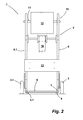
- the frame 2 consists essentially of two spaced-apart, in the illustrated embodiment, each made of a tube frame parts 6, 6.1 (see FIG. 2 ), which are connected in a manner not shown rigidly by transverse struts or other, the frame parts 6, 6.1 connecting elements together.
- the frame parts 6, 6.1 are designed largely L-shaped.
- the shorter leg 7 of each frame part 6, 6.1 serves as a holder of the frame parts 6, 6.1 connecting footrest 8.
- the longer legs 9 of the frame parts 6, 6.1 together form a support column unit.
- the longer legs 9 of the frame parts 6, 6.1 are formed in the region of their upper end to a support and handle member 10, which is designed in the illustrated embodiment as an open ring.
- the two frame parts 6, 6.1 are connected to an axle 11, to which in turn a padded supporting plate 12 serving as a thorax support is connected.
- a knee brace 13 At the height of the upper tibia of a person to be erected is a knee brace 13. At this support 13, the shins of a person can be supported.
- the knee brace 13 is in a manner not shown in the vertical direction relative to the frame parts 6, 6.1 set up.
- the erecting device 1 further has a generally designated by the reference numeral 14 lifting device comprising in the illustrated embodiment, an electric motor driven Gurtwinde 15 as a drive unit, a belt 16 as traction means and a seat belt 17 which is connected to the free end of the belt 16.
- the seat belt 17 serves as in FIG. 1 shown schematically, for grasping the buttocks of a person to be erected.
- To the frame 2 is further connected to each frame part 6, 6.1 associated support arm 18, with respect to its in FIG. 1 recognizable inclination 19 can be established by means of a longwall.
- connection holes 20 are in the frame parts 6, 6.1 introduced, it being provided that the strut 19 with its frame-side end according to the desired inclination in the respective connection opening 20 can be fixed.
- the strut 19 is hinged to the respective support arm 18.
- the pivot axis of the support arm 18 carries the reference numeral 21.
- An adjustment of Inclination of the support arm 18 can also be done by means of an electric motor drive or, for example, a manual spindle drive instead of the embodiment shown in the figures.
- the two support arms 18 are connected by a cross brace. This cross brace can also be designed as a tread.
- the erecting device 1 is for erecting a person 23, which is to be brought in the illustrated embodiment from a seated position to an upright position.
- the person 23 is raised by placing the feet of the same on the footrest 8 and placing the knees or the upper section of the shins against the knee brace 13.
- the seat belt 17 has been placed in a buttocks of the person 23 enclosing arrangement.
- the person 23 is not yet in the position provided for an erection.
- the person 23 will first move the feet further towards the front end of the device 1 until the knees and / or the upper portion of the lower legs contact the knee brace 13. If, starting from such a position, the lifting device 14 is actuated, the person 23 is due to the above-described support on the footrest 8 and the knee brace 13 in an upright position, as in FIG. 3 shown, brought. In this upright position, the rib cage is inserted between the support and grip elements 10 of the frame parts 6, 6.1, so that in this way the rib cage of the person 23 can experience a lateral guidance of the support. With his hands, not shown in the figures, the person 23 can grasp the end region of the support and grip elements 10 and hold on to it.
- the support plate 12 is either already in this erected position on the chest of the person 23 or is located at a small distance to this.
- the support plate 12 is, as in FIGS. 1 and 3 recognizable, on the axis 11 off-center hung up so that in FIG. 1 shown position is the typical rest position, which due to their articulated arrangement on the frame 2, the support plate adapts to the contour of the person to be supported in the region of her rib cage.
- the erecting device 1 is pivoted about the axis of rotation 4 of the wheels 3, 3.1 until the guide rollers 22 of the support arm 18 come into contact with the ground and thereby end the pivoting movement.
- Such a pivoting movement is exercised by gripping the support and gripping elements 10 by a caregiver or assistant, who typically places one foot against the strut connecting the two support arms 18 as an abutment.
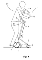
- This pivoted position of the erector 1 with the person 23 is in FIG. 4 shown. In this position, the center of gravity S of the person 23, including the pivoting unit formed by the frame 2 or erecting device 1 itself, is located behind the pivot axis 4 with respect to the executed pivoting direction.
- the weight of the person 23 as well as the pivoting unit acts on the support arms 18 and their swivel rollers 22.
- the swivel unit together with person 23 is in a stable over-center position.
- position of the seat belt 17 is no longer needed to hold the person 23, as this is securely held on the footrest 8, knee brace 13 and extending between the support and handle members 10 support plate 12. Consequently, the seat belt 17 can be loosened or removed in order to be able to loosen and lower the pants of the person 23, for example, for a toilet.
- the erecting device 1 without the body of the person 23 necessarily having to be held over additional train holding means.
- the in FIG. 4 shown tilting storage for the person 23 also not unpleasant.
- tilting storage of the person 23 can this, if desired, also be transported.
- the relatively large wheels 3, 3.1 ensure safe driving and the castors 22 a problem-free maneuvering.
- the support arm 18 may be relatively short, which facilitates driving with the erecting device 1, in particular the maneuvering.
- an electromotive drive can be used to drive the erecting device 1.
- the distance of the footrest 8 from the ground, despite the arranged thereon casters 5, 5.1 which can be basically designed as a glider, be low, since the support on these rollers 5, 5.1 ultimately only required for receiving the person 23.
- the low height of the footrest 8 ensures that it can be easily pushed with their bottom support under beds, chairs or the like. Furthermore, it is advantageous that the device can be designed with a short wheelbase, whereby a maneuvering the same, in particular with a person in their dumping person is possible.
- the device 1 can be designed as a self-propelled. In such a case, it is expedient if a tread is arranged abstützarm facility on which an assistant is able to stand in the pivoted position of the erecting device 1.
- the erecting device 1 is designed or adjusted in terms of Verschwenkbetrages that in the tilted storage position of the center of gravity is arranged sufficiently far behind the pivot axis 4 in order to avoid unintentional pivoting back.
- the amount of the executable pivoting movement is provided.
- the pivoting amount is less than 45 °. In most cases, a pivoting amount of 15-30 ° should be sufficient, without this having to be explained in detail in the context of these statements.
- FIG. 5 shows a further erecting device 1.1, which basically the erecting device 1 of FIGS. 1 to 4 equivalent. Therefore, the same parts are also identified by the same reference numerals.
- the erecting device 1.1 has in addition to the features of Aufrichteech 1 via a Kipp Klischsmechanismus 24.
- the anti-tilt mechanism 24 is used to prevent pivoting back of the erector 1.1, after this from its in FIG. 5 shown position in their in FIG. 6 shown pivoted position has been brought.
- the anti-tilt mechanism 24 is in the position of the erector 1.1 in FIG. 5 not activated.
- the anti-tilt mechanism 24 has a swivel foot 25 arranged below the footrest 8.
- the swivel foot 25 is pivotable about a pivot axis arranged parallel to the axis of rotation 4 of the wheel 3.
- the swivel foot 25 is adjustable by an adjusting lever 26, which in turn is connected to an actuating lever 27 articulated.
- the actuating lever 27 is designed in the illustrated embodiment as an angle and mounted in the region of the end of its longer leg 28 pivotally mounted on the strut 19. In the FIG. 5 shown end position of the actuating lever 27 is not stop limit in a manner not shown in detail.
- a tension spring 29 keeps the operating lever 7 pressed against the stop.
- the anti-tilt mechanism 24 can be actuated for pivoting the pivot foot 25.
- the operating lever 27 in the FIG. 5 adjusted arrow direction. In the course of this movement, this is moved over the defined by the tension spring 29 dead center and is located in the in FIG. 6 shown position against another stop acting and held by the tension spring 29 in this position.
- the swivel foot 25 is swung out and is supported on the ground. Consequently, a pivoting back of the erector 1.1 in the in FIG. 5 shown basic position not possible.
- the anti-tilt mechanism 24 must first be brought into its other position.
- the actuating lever 27 is manually operated in the illustrated embodiment by the erecting device 1.1 serving person.
- an actuator to arrange on the support and handle element, via which then the operating lever 27 is moved in one or the other position.
- Such a tilt lock is used to prevent inadvertent pivoting back of the erector 1.1, such as unintentional movements of the person supported thereon 23rd
- the anti-tilt mechanism 24 includes a swivel foot 25.
- the Kipp Klischsmechanismus with two pivoting feet, of which then each one under the respective, the leg 7 forming tube of the footrest is arranged.
- a righting device to design these gorgeneinrichtbar.
- Suchciteneinricht sadness is used to adjust the frame of the erector to different body sizes so people to be erected.
- the frame is telescopically extendable and lockable at different heights, preferably at a point above the arrangement of the lifting device and below the belt deflecting role.
Landscapes
- Health & Medical Sciences (AREA)
- Life Sciences & Earth Sciences (AREA)
- Animal Behavior & Ethology (AREA)
- General Health & Medical Sciences (AREA)
- Public Health (AREA)
- Veterinary Medicine (AREA)
- Nursing (AREA)
- Invalid Beds And Related Equipment (AREA)
Description
Die Erfindung betrifft eine Einrichtung zum Aufrichten einer Person, insbesondere aus einer sitzenden Stellung, umfassend eine Fußauflage, eine Kniestütze und eine einen Antrieb und ein von diesem bewegbares Zugmittel aufweisende Hebeeinrichtung.The invention relates to a device for erecting a person, in particular from a sitting position, comprising a footrest, a knee brace and a drive and a movable traction means comprising this lifting device.
Derartige Einrichtungen werden auch als Aufrichtelifter bezeichnet. Eingesetzt werden derartige Lifter zum Aufrichten einer bezüglich ihrer Bewegungsfreiheit eingeschränkten Person beispielsweise zum Umsetzen dieser Person von einem Bett in einen Rollstuhl oder von einem Rollstuhl auf eine Toilette. Derartige Aufrichtelifter verfügen über ein Gestell, welches bodenseitig typischerweise über vier Lenkrollen abgestützt ist. Teil des Gestells ist eine sich in vertikaler Richtung nach oben erstreckende Tragsäule, an der eine für jeden Fuß vorgesehene Fußauflage sowie eine Knie- bzw. Schienbeinstütze angebracht ist. An die Tragsäule sind zudem Haltegriffe angeschlossen, damit sich eine aufzurichtende Person hieran festhalten kann. Die Tragsäule gemäß einem vorbekannten Aufrichtelifter verfügt an ihrem oberen Abschluss, der sich oberhalb einer aufgerichteten Person befindet, über eine Umlenkrolle, an der ein Zugmittel, angeschlossen an eine elektromotorisch betriebene Seilwinde, umgelenkt ist. An dem freien Ende eines solchen, als Zugmittel dienenden Seiles ist eine gepolsterte Aufrichtschale befestigt, die zum Aufrichten einer Person um den Rücken derselben herum gelegt wird. Mit einem solchen vorbekannten Aufrichtelifter kann eine Person aus sitzender Position, in eine schräge, nach hinten geneigte Stehposition gebracht werden. In dieser Stellung stehen die Füße auf den Fußauflagen auf und die Knie bzw. die Schienbeine liegen an der diesbezüglichen Abstützung als Widerlager an. Ein Aufrichten einer Person in eine normale Stehposition ist mit einem solchen Lifter nicht möglich. Darüber hinaus kann ein solcher Lifter nur für solche Personen eingesetzt werden, die in der Lage sind, die den Rücken umgreifende und unter den Armen hindurchgeführte Aufrichtschale in dieser Stellung unter den Achseln halten zu können. Personen mit Muskelerkrankungen sind jedoch oftmals nicht in der Lage, diesen Gegendruck zum Halten der Aufrichteschale aufzubringen. In solchen Fällen werden Gesäßgurte verwendet. Der Einsatz eines Gesäßgurtes hat wiederum zum Nachteil, dass bei einem Toilettengang die Hose nicht, zumindest nicht ohne weiteres heruntergelassen werden kann.Such devices are also referred to as Aufrichtelifter. Such lifters are used for erecting a person restricted in terms of their freedom of movement, for example for transferring this person from a bed into a wheelchair or from a wheelchair to a toilet. Such Aufrichtelifter have a frame, which is supported on the bottom side typically four castors. Part of the frame is a vertically upwardly extending support column to which a provided foot for each foot and a knee or shin support is attached. Handrails are also connected to the support column, so that a person to be erected can hold on to it. The support column according to a previously known Aufrichtelifter has at its upper end, which is located above an upright person, via a pulley on which a traction device connected to an electric motor operated winch, is deflected. At the free end of such, serving as a traction cable a padded Aufrichtschale is attached, which is placed for erecting a person around the back of the same. With such a known Aufrichtelifter a person from a sitting position, can be placed in an inclined, backward inclined standing position. In this position, the feet are on the footrests and the knees and the shins are on the relevant support as an abutment. A raising a person in a normal standing position is not possible with such a lifter. In addition, such a lifter can be used only for those persons who are able to hold around the back and passing under the arms erecting dish in this position under the armpits can. However, individuals with muscle disorders often are unable to apply this back pressure to hold the erecting cup. In such cases, harness straps are used. The use of a seat belt in turn has the disadvantage that at a toilet the trousers not, at least not be lowered easily.
Neben derartigen aufgrund ihrer Rollen mobilen Aufrichteliftem werden auch Stehgeräte eingesetzt, mit denen eine Person mittels eines Gesäßgurtes in den Stand gebracht werden kann. Zum Umsetzen einer aufgerichteten Person ist die Tragsäule bei einem solchen Stehgerät drehbar.In addition to such due to their roles mobile Aufrichteliftem standing devices are used with which a person can be brought by means of a seat belt in the state. To implement an erect person, the support column is rotatable in such a standing device.
Um bei Verwendung eines Gesäßgurtes ein Lösen der Hose zu ermöglichen und gleichzeitig ein Zurückfallen der Person zu verhindern, ist es erforderlich, die aufgerichtete Person mit einem zusätzlichen Haltegurt zu fixieren. Auch wenn bei Verwendung eines Gesäßgurtes ein Umsetzen einer Person insbesondere auch für einen Toilettengang möglich ist, kann die Person mit dem zusätzlichen Haltegurt nur dann gehalten werden, wenn von dieser der notwendige Gegendruck aufgebaut werden kann. Personen beispielsweise mit Muskelerkrankungen sind hierzu nicht immer in der Lage.In order to enable loosening of the pants when using a seat belt and at the same time to prevent falling back of the person, it is necessary to fix the upright person with an additional tether. Even if using a buttock, a transfer of a person in particular for a toilet is possible, the person with the additional tether can be held only if the necessary back pressure can be built from this. People with muscle diseases, for example, are not always able to do this.
Ausgehend von diesem diskutierten Stand der Technik (Sehen auch die Dokumente
Diese Aufgabe wird gemäβ dem Anspruch 1 durch eine eingangs genannte, gattungsgemäße Einrichtung gelöst, bei der die Einrichtung über eine Brustkorbabstützung zum Abstützen des Brustkorbes einer mit der Einrichtung aufgerichteten Person verfügt und die zumindest eine Brustkorbabstützung, die Kniestütze sowie die Fußauflage als Schwenkeinheit zum Schwenken einer aufgerichteten Person in Richtung der Aufrichtebewegung um eine horizontal verlaufende Achse verschwenkbar sind.This object is achieved according to
Diese Aufrichteeinrichtung verfügt über eine Schwenkeinheit, die es ermöglicht, die aufgerichtete Person zu verschwenken, damit nach Durchführen des Verschwenkvorganges die Person an der Schwenkeinheit abgestützt ist. Aus diesem Grunde werden zum Halten der Person nach dem Verschwenken keine zusätzlichen Halte- oder Fixiermittel benötigt. Das Gewicht der Person wird über die Fußauflage, die Knie- und/oder Schienbeinstütze und eine Brustkorbabstützung aufgefangen. Verschwenkt zu werden braucht die aufgerichtete Person nur so weit, dass diese schwerkraftbedingt nicht wieder zurückfällt. Bei einer Aufrichteeinrichtung, die, wie in einem bevorzugten Ausführungsbeispiel vorgesehen, einen sehr tief liegenden Schwenkpunkt hat, braucht der Verschwenkbetrag nicht sonderlich groß zu sein, um eine Person nach Aufrichten derselben in die Abstützlagerung nach dem Verschwenkvorgang zu bringen. Da das Gewicht der aufgerichteten und zusammen mit der Schwenkeinheit verschwenkten Person über die Schwenkeinheit aufgefangen wird und aus diesem Grunde zusätzliche Haltesysteme grundsätzlich nicht benötigt werden, kann in dieser Position das zum Aufrichten der Person verwendete Zugmittel, beispielsweise ein Gesäßgurt, eine Gesäßschale oder auch eine Aufrichtschale gelöst werden. Vor allem bei der Verwendung eines Gesäßhebezeuges kann dieses gelöst und etwa für einen Toilettengang ohne Weiteres die Hose der Person heruntergelassen werden. Während dieser Zeit ist die Person durch die Schwenkeinheit abgestützt. Allein unterstützend kann, wenn benötigt, ein zusätzliches Haltesystem zum Halten der Person auch in dieser Lage eingesetzt werden. Bei Einsatz eines solchen zusätzlichen Haltesystems ist allerdings hervorzuheben, dass im Unterschied zu vorbekannten Aufrichteeinrichtungen von diesem zusätzlichen Haltesystem nur ein Bruchteil der zum Halten einer Person notwendigen Kraft auf die Person einwirkt und daher derartige zusätzliche Haltemittel auch bei solchen Personen eingesetzt werden können, die ansonsten mit derartigen Haltesystemen nicht gehalten werden können.This Aufrichteeinrichtung has a pivoting unit, which makes it possible to pivot the erect person so that after performing the pivoting the person is supported on the pivoting unit. For this reason, to keep the person after the Pivoting requires no additional holding or fixing. The weight of the person is absorbed via the footrest, knee and / or tibial support and chest support. The upright person only needs to be pivoted so far that they do not fall back due to gravity. In a righting device, which, as provided in a preferred embodiment, has a very low-lying pivot point, the pivoting amount does not need to be particularly large to bring a person after erecting the same in the support bearing after Verschwenkvorgang. Since the weight of the upright and pivoted together with the pivoting unit person is collected on the pivot unit and for this reason additional holding systems are not needed in principle, used in this position for erecting the person traction means, such as a seat belt, a buttocks or a Aufrichtschale be solved. Especially when using a buttocks lifting this can be solved and lowered for a toilet easily without the pants of the person. During this time the person is supported by the swivel unit. Alone supportive, if needed, an additional holding system for holding the person can be used even in this situation. When using such an additional holding system, however, it should be emphasized that, in contrast to previously known erecting devices of this additional holding system only a fraction of the force necessary to hold a person force acts on the person and therefore such additional holding means can be used even in such persons who otherwise with such holding systems can not be maintained.
Gemäß einem Ausführungsbeispiel ist vorgesehen, dass die Schwenkeinheit während des Vorganges des Verschwenkens über einen Totpunkt verschwenkt wird und somit diese zusammen mit der damit verschwenkten Person in ihrer verschwenkten Stellung sich in einer Übertotpunktstellung befindet. Es ist dann nicht notwendig, in den Endstellungen der Aufrichteeinrichtung zusätzliche Sicherungseinrichtungen zum Halten der Schwenkeinheit in diesen Stellungen vorzusehen. Eine solche Übertotpunktstellung ist typischerweise anschlagbegrenzt. Bei einer solchen Ausgestaltung befindet sich der Schwerpunkt der Schwenkeinheit mit einer daran angeschlossenen Person zu Beginn des Schwenkvorganges zum Aufrichten der Person in einer Position in Schwenkrichtung gesehen vor der Schwenkachse und nach Abschluss des Schwenkvorganges hinter der Schwenkachse. Die Schwenkeinheit ist bei einer solchen Ausgestaltung somit als Wippe konzipiert.According to one embodiment, it is provided that the pivoting unit is pivoted during the process of pivoting about a dead center and thus this together with the person pivoted therewith in its pivoted position is in an over-center position. It is then not necessary to provide additional securing devices for holding the swivel unit in these positions in the end positions of the erecting device. Such an over-center position is typically limit stop. In such an embodiment, the center of gravity of the pivoting unit with a person connected to it is at the beginning of the pivoting operation for Erecting the person in a position seen in the pivoting direction in front of the pivot axis and after completion of the pivoting process behind the pivot axis. The pivoting unit is thus designed as a rocker in such a configuration.
Eine solche Schwenkeinheit kann schwenkbar an ein Gestell oder eine Standeinheit angeschlossen sein, wobei der Verschwenkvorgang manuell, auch durch die darauf befindliche Person selbst, oder durch einen Antrieb, beispielsweise einen elektromotorischen Antrieb ausgeführt werden kann. Das Gestell selbst ist bei einer solchen Ausgestaltung gegenüber der Schwenkeinheit feststehend. Gemäß einem sich hiervon unterscheidenden Ausführungsbeispiel ist vorgesehen, dass das Gestell selbst über seine bodenseitige Abstützung, vorzugsweise einen Totpunkt überwindend, verschwenkt werden kann. Bei einer solchen Ausgestaltung bildet die Schwenkachse das Hebellager eines zweiarmigen Hebels, von dem die Fußauflage den kürzeren Hebelarm und ein sich winklig an die Fußauflage anschließender Abschnitt des Gestells, der bei vorbekannten Liftern der Tragsäule entspricht, den längeren Hebelarm bildet. Die bodenseitige Abstützung kann über ein Wipplager erfolgen, welches beispielsweise durch zwei voneinander beabstandete Rollen bzw. deren Drehachse gebildet wird. Aufgrund der vorbeschriebenen Hebelübersetzung ist ein Verschwenken selbst einer schweren, an die Schwenkeinheit angeschlossenen Person nach Aufrichten derselben in die verschwenkte Stellung für das Pflegepersonal ohne größere Kraftanstrengung möglich. Als Anschlag dient bei einer solchen Ausgestaltung beispielsweise ein der Fußauflage bezüglich des Hebellagers gegenüberliegender Anschlagarm, der sich in der verschwenkten Stellung der Schwenkeinheit bodenseitig abstützt. In der anderen Stellung befindet sich dieser Anschlagarm dagegen nicht in Bodenkontakt. In einer Weiterbildung ist vorgesehen, die Aufrichteeinrichtung mit einem Kippsicherungsmechanismus auszurüsten, damit, wenn betätigt, die Aufrichteeinrichtung nach dem Verschwenken nicht unbeabsichtigt wieder in die Ausgangsstellung zurückschwenkt.Such a pivot unit may be pivotally connected to a frame or a stand unit, wherein the pivoting operation manually, even by the person thereon, or by a drive, such as an electric motor drive can be performed. The frame itself is fixed in such a configuration relative to the pivoting unit. According to an embodiment which differs therefrom, it is provided that the frame itself can be pivoted via its base-side support, preferably overcoming a dead center. In such an embodiment, the pivot axis forms the lever bearing of a two-armed lever, of which the footrest forms the shorter lever arm and an angularly adjoining the footrest portion of the frame, which corresponds in prior art lifters of the support column, the longer lever arm. The bottom-side support can be made via a Wipplager, which is formed for example by two spaced apart rollers or their axis of rotation. Due to the above leverage pivoting even a heavy, connected to the swivel unit person after raising the same in the pivoted position for the nursing staff without much effort is possible. As a stop is used in such a configuration, for example, one of the footrest with respect to the lever bearing opposite stop arm, which is supported on the bottom side in the pivoted position of the pivot unit. In the other position, however, this stop arm is not in contact with the ground. In a further development, it is provided to equip the righting device with a Kippsicherungsmechanismus, so that when actuated, the righting device does not swing back unintentionally after pivoting back into the starting position.
Die Hebeeinrichtung ist bei einer solchen Ausgestaltung Teil der Schwenkeinheit und wird mit dieser aus der einen in die andere Stellung verschwenkt. Da eine aufzurichtende Person typischerweise mit einem Gesäß- oder Lendengurt aufgerichtet wird, während sich die Füße der aufzurichtenden Person auf der Fußauflage und die Knie bzw. Schienbeine an der diesbezüglichen Abstützung abstützen, ist es nicht erforderlich, das typischerweise als Seil oder Gurt eingesetzte Zugmittel über die Höhe des Brustkorbes einer aufzurichtenden Person führen zu müssen. In der aufgerichteten Stellung kann dieses sich außerhalb des Gesichtsbereiches der aufgerichteten Person befinden.The lifting device is in such a configuration part of the pivot unit and is pivoted with this from one to the other position. Since a person to be upright is typically erected with a buttock or lumbar while the feet of the To be supported on the footrest and support the knees or shins on the relevant support, it is not necessary to have to use the typically used as a rope or belt traction over the height of the chest of a person to be raised. In the upright position, this may be outside the facial area of the erect person.
Weitere Vorteile und weitere Ausgestaltungen der Erfindung ergeben sich auch aus der nachfolgenden Beschreibung eines Ausführungsbeispiels unter Bezugnahme auf die beigefügten Figuren. Es zeigen:
- Fig. 1:
- eine schematisierte Seitenansicht einer Aufrichteeinrichtung in einer ersten Stellung derselben mit einer daran angeschlosse- nen aufzurichtenden Person,
- Fig. 2:
- eine Stirnseitenansicht der Aufrichteeinrichtung der
Figur 1 - Fig. 3:
- die Aufrichteeinrichtung der
Figur 1 - Fig. 4:
- die Aufrichteeinrichtung der
Figur 3 - Fig. 5:
- die Aufrichteeinheit der
Figuren 1 bis 4 - Fig. 6:
- die Aufrichteeinheit der
Figur 5
- Fig. 1:
- 1 is a schematic side view of a straightening device in a first position thereof with a person to be strapped thereto,
- Fig. 2:
- an end view of the erector of the
FIG. 1 . - 3:
- the erecting device of
FIG. 1 with the person in an upright position, - 4:
- the erecting device of
FIG. 3 with the attached person standing in a second position of the institution, - Fig. 5:
- the erection unit of
FIGS. 1 to 4 with an additional anti-tilt device with non-actuated anti-tilt mechanism and - Fig. 6:
- the erection unit of
FIG. 5 after pivoting the same and pressing the Kippsicherungsmechanismusses.
Eine Aufrichteeinrichtung 1 zum Aufrichten einer Person aus einer sitzenden Stellung in eine aufgerichtete stehende Stellung verfügt über ein Gestell 2. Das Gestell 2 ist bodenseitig durch zwei voneinander beabstandete Räder 3, 3.1 abgestützt. Die Drehachse der Räder 3, 3.1 ist in
Die Aufrichteeinrichtung 1 verfügt des Weiteren über eine insgesamt mit dem Bezugszeichen 14 gekennzeichnete Hebeeinrichtung, umfassend bei dem dargestellten Ausführungsbeispiel eine elektromotorisch betriebene Gurtwinde 15 als Antriebseinheit, einen Gurt 16 als Zugmittel sowie einen Gesäßgurt 17, der an das freie Ende des Gurtes 16 angeschlossen ist. Der Gesäßgurt 17 dient, wie in
In der in
Um den Gesäßgurt 17 von der Person 23 lösen zu können, wird die Aufrichteeinrichtung 1 um die Drehachse 4 der Räder 3, 3.1 verschwenkt, bis die Lenkrollen 22 des Abstützarms 18 in Bodenkontakt gelangen und dadurch die Verschwenkbewegung beenden. Eine solche Verschwenkbewegung wird durch Ergreifen der Stütz- und Griffelemente 10 durch eine Pflege- oder Hilfsperson ausgeübt, die typischerweise einen Fuß gegen die die beiden Abstützarme 18 verbindenden Streb als Widerlager stellt. Diese verschwenkte Stellung der Aufrichteeinrichtung 1 mit der Person 23 ist in
Aus ihrer in
In der in
In Bezug auf die Ausübung der Verschwenkbewegung bilden die Schenkel 9 des Gestells 2 mit dem oberen, bei dem dargestellten Ausführungsbeispiel als Stütz- und Griffelement 10 ausgebildeten Ende den längeren Hebel eines zweiarmigen Hebels aus mit der Folge, dass das Verschwenken einer auch schwereren Person ohne großen Kraftaufwand für das Pflegepersonal oder auch eine Hilfsperson möglich ist.With regard to the exercise of the pivoting movement form the
Die Einrichtung 1 kann als Selbstfahrer konzipiert sein. In einem solchen Fall ist es zweckmäßig, wenn eine Trittstufe abstützarmseitig angeordnet ist, auf der eine Hilfsperson in der verschwenkten Stellung der Aufrichteeinrichtung 1 zu stehen vermag.The
Es versteht sich, dass die Aufrichteeinrichtung 1 hinsichtlich des Verschwenkbetrages so konzipiert ist oder eingestellt wird, dass in der Kipplagerungsstellung der Schwerpunkt hinreichend weit hinter der Schwenkachse 4 angeordnet ist, um ein unbeabsichtigtes Zurückschwenken zu vermeiden. Je nach Ausgestaltung ist daher der Betrag der ausführbaren Verschwenkbewegung vorgesehen. Typischerweise ist der Verschwenkbetrag kleiner als 45°. Zumeist dürfte ein Verschwenkbetrag von 15-30° hinreichend sein, ohne dass dieses im Rahmen dieser Ausführungen im einzelnen dargelegt werden müsste.It is understood that the erecting
Nachdem die Aufrichteeinrichtung 1.1 mit der Person 23 verschwenkt worden ist, kann der Kippsicherungsmechanismus 24 zum Ausschwenken des Schwenkfußes 25 betätigt werden. Zu diesem Zweck wird der Betätigungshebel 27 in der
Der Betätigungshebel 27 wird bei dem dargestellten Ausführungsbeispiel manuell durch die die Aufrichteeinrichtung 1.1 bedienende Person betätigbar. Selbstverständlich ist es ohne Weiteres möglich, eine Betätigungseinrichtung an dem Stütz- und Griffelement anzuordnen, über welches sodann der Betätigungshebel 27 in die eine oder andere Stellung bewegt wird.The actuating
Eine solche Kippsicherung dient zum Verhindern eines unbeabsichtigten Rückschwenkens der Aufrichteeinrichtung 1.1, etwa bei unbeabsichtigten Bewegungen der darauf abgestützten Person 23.Such a tilt lock is used to prevent inadvertent pivoting back of the erector 1.1, such as unintentional movements of the person supported thereon 23rd
Da die Aufrichteeinrichtung 1.1 der in
In einer in den Figuren nicht dargestellten Weiterbildung ist bei einer Aufrichteeinrichtung vorgesehen, diese höheneinrichtbar zu konzipieren. Eine solche Höheneinrichtbarkeit dient zum Anpassen des Gestells der Aufrichteeinrichtung an unterschiedliche Körpergrößen damit aufzurichtenden Personen. Zu diesem Zweck ist das Gestell teleskopartig verlängerbar und in unterschiedlichen Höhen verriegelbar, und zwar vorzugsweise an einer Stelle oberhalb der Anordnung der Hebeeinrichtung und unterhalb der den Gurt umlenkenden Rolle.In a further embodiment, not shown in the figures is provided at a righting device to design these höheneinrichtbar. Such Höheneinrichtbarkeit is used to adjust the frame of the erector to different body sizes so people to be erected. For this purpose, the frame is telescopically extendable and lockable at different heights, preferably at a point above the arrangement of the lifting device and below the belt deflecting role.
Die Beschreibung der Erfindung ist anhand von Ausführungsbeispielen beschrieben worden. Ohne den Umfang der Ansprüche zu verlassen, ergeben sich für einen Fachmann zahlreiche weitere Ausgestaltungen, die Erfindung verwirklichen zu können.The description of the invention has been described with reference to embodiments. Without departing from the scope of the claims, numerous further embodiments for a person skilled in the art will be able to realize the invention.
- 1, 1.11, 1.1
- AufrichteeinrichtungAufrichteeinrichtung
- 22
- Gestellframe
- 3,3.13,3.1
- Radwheel
- 44
- Drehachseaxis of rotation
- 5, 5.15, 5.1
- Lenkrollecastor
- 6, 6.16, 6.1
- Gestellteilframe part
- 77
- Schenkelleg
- 88th
- Fußauflagefootrest
- 99
- Schenkelleg
- 1010
- Stütz- und GriffelementSupport and grip element
- 1111
- Achseaxis
- 1212
- Stützplattesupport plate
- 1313
- Kniestützeknee brace
- 1414
- Hebeeinrichtunglifter
- 1515
- GurtwindeCord winch
- 1616
- Gurtbelt
- 1717
- GesäßgurtGesäßgurt
- 1818
- Abstützarmsupport arm
- 1919
- Strebface
- 2020
- Anschlussöffnungport opening
- 2121
- Schwenkachseswivel axis
- 2222
- Lenkrollecastor
- 2323
- Personperson
- 2424
- KippsicherungsmechanismusKippsicherungsmechanismus
- 2525
- Schwenkfußswivel
- 2626
- Stellhebellever
- 2727
- Betätigungshebelactuating lever
- 2828
- Schenkelleg
- 2929
- Zugfedermainspring
- SS
- Schwerpunktmain emphasis
Claims (14)
- A device for raising a person up, in particular out of a seated position, comprising a foot support (8), a knee support (13) and a lifting unit (14) exhibiting a drive (15) and a traction unit (16, 17) movable by said drive, the device (1, 1.1) being provided with a chest support (12) for supporting the chest of a person (23) being raised up by the device (1, 1.1), wherein the at least one chest support (12), the knee support (13) and the foot support (8) can be deflected as a swivelling unit for swivelling a raised person (23) about a horizontally aligned axis (4) in the direction of the raising motion.
- A device according to claim 1 wherein the swivel axis (4) exhibits a space coordinate such that the swivelling operation displaces the centre of gravity (S) of the swivelling unit with a person (23) supported on it out of a position that is in front of the swivel axis (4) in swivelling direction at the start of the swivelling operation and into a position that is behind the swivel axis (4) at the end of the swivelling operation.
- A device according to claim 1 or 2 wherein the swivelling motion of the swivelling unit is limited by a stop (18, 22).
- A device according to claim 3 wherein the position of the stop (18, 22) is adjustable for setting the executable swivelling amount of the swivelling unit.
- A device according to any one of claims 1 to 4 wherein the device (1, 1.1) comprises a frame (2) to which the foot support (8), the knee support (13), the chest support (12) and the lifting unit (14) are attached, and the frame (2) is supported at the floor end by a rocker bearing defining the swivel axis (4) of the swivelling unit formed by the frame (2).
- A device according to claim 5 wherein the foot support (8) forms the one arm of a two-armed lever supported in the rocker bearing and with its plane arranged an angle [sic] with a frame section (9) extending essentially parallel to a person (23) raised up with the device, this frame section (9) forming a second lever arm in relation to the bearing (4) of the lever.
- A device according to claim 6 wherein the frame (2) exhibits at least one support arm (18) for providing a stop limiting the swivelling motion by a support at the bottom which forms a second lever arm in relation to the foot support (8) and the rocker bearing (4).
- A device according to any one of claims 5 to 7 wherein the rocker bearing is formed by two rollers or wheels (3, 3.1) which are spaced apart from one another, are rotatably connected to the frame (2) and whose axis of rotation (4) is the swivel axis of the swivelling unit.
- A device according to claim 8 wherein the foot support (8) and/or the at least one support arm (18) has rollers (5, 5.1; 22) or slides providing floor support.
- A device according to any one of claims 1 to 9 wherein the frame (2) exhibits a preferably pivotably mounted support plate (12) for providing chest support.
- A device according to any one of claims 1 to 10 wherein the lifting unit (14) is provided with an electromotive belt winch or cable winch (15) as drive, and a belt (16) or a cable is provided as movable traction means in adaptation to the drive.
- A device according to claim 11 wherein a carrying and/or supporting element such as a bowl or cloth for supporting the person (23) to be raised, is attached to the traction means (16) for the raising operation.
- A device according to any one of claims 5 to 12 wherein the device (1.1) is provided with an adjustable anti-tilt mechanism (24) which when actuated prevents the device (1.1) tilting back into its initial position.
- A device according to claim 13 wherein the anti-tilt mechanism (24) is executed as a link chain having two stable end positions.
Applications Claiming Priority (1)
| Application Number | Priority Date | Filing Date | Title |
|---|---|---|---|
| DE202009004889U DE202009004889U1 (en) | 2009-06-04 | 2009-06-04 | Device for erecting a person |
Publications (2)
| Publication Number | Publication Date |
|---|---|
| EP2258331A1 EP2258331A1 (en) | 2010-12-08 |
| EP2258331B1 true EP2258331B1 (en) | 2012-06-20 |
Family
ID=41795434
Family Applications (1)
| Application Number | Title | Priority Date | Filing Date |
|---|---|---|---|
| EP10164025A Active EP2258331B1 (en) | 2009-06-04 | 2010-05-27 | Device for propping up a person |
Country Status (2)
| Country | Link |
|---|---|
| EP (1) | EP2258331B1 (en) |
| DE (1) | DE202009004889U1 (en) |
Cited By (1)
| Publication number | Priority date | Publication date | Assignee | Title |
|---|---|---|---|---|
| DE102022004008A1 (en) | 2022-10-26 | 2024-05-02 | Eckart Baum | Device for providing a single-person workstation for a physically disabled worker who is dependent on a wheelchair |
Families Citing this family (8)
| Publication number | Priority date | Publication date | Assignee | Title |
|---|---|---|---|---|
| JP5588271B2 (en) * | 2010-08-19 | 2014-09-10 | 国立大学法人茨城大学 | Assistance transfer device |
| DE102010041802A1 (en) | 2010-09-30 | 2012-04-05 | Siemens Aktiengesellschaft | Device for erecting patient with limited mobility from lying position by care personal, has coupling element introducing force application on device so that person erecting movement from dorsal position into sitting position is supported |
| DE202011100758U1 (en) | 2011-05-16 | 2011-09-05 | Leonair Gmbh | Patient lifting device |
| ITNA20110039A1 (en) * | 2011-09-15 | 2013-03-16 | Stefano Troncone | WHEELCHAIR FOR DISABLED PEOPLE CONVERTIBLE IN A SYSTEM THAT ALLOWS USERS TO STAY THE BALANCE OF TWO-WHEELED CARS ON THE BALANCE |
| DE102014108755B4 (en) | 2014-06-23 | 2017-03-23 | Leonair Gmbh | Patientenaufstehhilfe |
| JP6357932B2 (en) * | 2014-07-08 | 2018-07-18 | 株式会社ジェイテクト | Assistance support device |
| CN112353599B (en) * | 2020-11-09 | 2022-04-29 | 赵秋芬 | Operating room nursing device |
| DE102024204020A1 (en) * | 2024-04-29 | 2025-10-30 | Rehatec GmbH | Standing device for standing training of one person |
Family Cites Families (5)
| Publication number | Priority date | Publication date | Assignee | Title |
|---|---|---|---|---|
| US4290423A (en) * | 1980-04-25 | 1981-09-22 | Main-Tainer Corporation | Paraplegic stand having a lift mechanism |
| US4510633A (en) * | 1982-12-20 | 1985-04-16 | Thorne Mark W | Invalid transfer means |
| US5233708A (en) * | 1992-07-30 | 1993-08-10 | Cindylift Products, Inc. | Patient transfer apparatus |
| AU3673295A (en) * | 1994-10-14 | 1996-05-06 | Ikeda Mohando Co., Ltd. | Posture change system and posture change method |
| DE10133340A1 (en) * | 2001-07-12 | 2003-01-23 | Detlef Gausepohl | Raising, lowering physically handicapped persons involves fixing arms in position at about 90 degrees to vertical, applying traction force then vertical lifting force to raise to standing position |
-
2009
- 2009-06-04 DE DE202009004889U patent/DE202009004889U1/en not_active Expired - Lifetime
-
2010
- 2010-05-27 EP EP10164025A patent/EP2258331B1/en active Active
Cited By (1)
| Publication number | Priority date | Publication date | Assignee | Title |
|---|---|---|---|---|
| DE102022004008A1 (en) | 2022-10-26 | 2024-05-02 | Eckart Baum | Device for providing a single-person workstation for a physically disabled worker who is dependent on a wheelchair |
Also Published As
| Publication number | Publication date |
|---|---|
| DE202009004889U1 (en) | 2010-03-04 |
| EP2258331A1 (en) | 2010-12-08 |
Similar Documents
| Publication | Publication Date | Title |
|---|---|---|
| EP2258331B1 (en) | Device for propping up a person | |
| DE69529058T2 (en) | FOOT EXIT FOR SEAT BED | |
| DE3420342C2 (en) | ||
| DE3752081T2 (en) | Orthopedic carriage | |
| DE102011006359A1 (en) | Mobility device for physically handicapped persons | |
| DE1930886A1 (en) | Device for handling weakened patients or the physically handicapped | |
| CH541326A (en) | Lifting and transport device for a disabled person | |
| DE3635117A1 (en) | INVALID LIFTING DEVICE | |
| DE69933582T2 (en) | Lifting device with lateral supports | |
| DE1491264A1 (en) | Device for receiving sick or physically handicapped people | |
| EP0584121B1 (en) | Wheelchair, in particular for paraplegics | |
| EP3842021B1 (en) | Transfer system and method for repositioning persons | |
| DE1241558B (en) | Device for lifting a physically handicapped, seated person | |
| DE10133340A1 (en) | Raising, lowering physically handicapped persons involves fixing arms in position at about 90 degrees to vertical, applying traction force then vertical lifting force to raise to standing position | |
| EP2559412B1 (en) | Appareil de levage de personnes avec fonctions supplémentaires | |
| DE102011009899A1 (en) | Movable device for transfer of persons in need of care and for therapeutic purposes, has role-mounted chassis, on which vertical support is arranged, and support is arranged on chassis in rotatable manner | |
| DE2126257C3 (en) | Hospital elevator | |
| DE4424118C1 (en) | Bed, esp. hospital or treatment bed | |
| DE3019299C2 (en) | Orthopedic self-propelled bed | |
| DE20000380U1 (en) | Transfer device for wheelchair users, people with reduced mobility and the like. | |
| DE102008027793A1 (en) | Treatment chair i.e. arm chair, for use during e.g. dialysis treatment of patient in dialysis station, has leg support moved into seat surface in lowered deep position and unlockable during advancing movement in raised horizontal position | |
| DE20013730U1 (en) | Device for moving, in particular, disabled people | |
| DE102024000301A1 (en) | Wheelchair with fully retractable backrest | |
| DE102004034641B4 (en) | Footrest for wheelchairs or wheelchairs | |
| DE19643112A1 (en) | Gymnastic apparatus with rings for spatial movement |
Legal Events
| Date | Code | Title | Description |
|---|---|---|---|
| PUAI | Public reference made under article 153(3) epc to a published international application that has entered the european phase |
Free format text: ORIGINAL CODE: 0009012 |
|
| AK | Designated contracting states |
Kind code of ref document: A1 Designated state(s): AL AT BE BG CH CY CZ DE DK EE ES FI FR GB GR HR HU IE IS IT LI LT LU LV MC MK MT NL NO PL PT RO SE SI SK SM TR |
|
| AX | Request for extension of the european patent |
Extension state: BA ME RS |
|
| 17P | Request for examination filed |
Effective date: 20110411 |
|
| REG | Reference to a national code |
Ref country code: DE Ref legal event code: R079 Ref document number: 502010000901 Country of ref document: DE Free format text: PREVIOUS MAIN CLASS: A61G0007100000 Ipc: A61G0005140000 |
|
| RIC1 | Information provided on ipc code assigned before grant |
Ipc: A61G 7/10 20060101ALI20111025BHEP Ipc: A61G 5/14 20060101AFI20111025BHEP |
|
| GRAP | Despatch of communication of intention to grant a patent |
Free format text: ORIGINAL CODE: EPIDOSNIGR1 |
|
| GRAS | Grant fee paid |
Free format text: ORIGINAL CODE: EPIDOSNIGR3 |
|
| GRAA | (expected) grant |
Free format text: ORIGINAL CODE: 0009210 |
|
| AK | Designated contracting states |
Kind code of ref document: B1 Designated state(s): AL AT BE BG CH CY CZ DE DK EE ES FI FR GB GR HR HU IE IS IT LI LT LU LV MC MK MT NL NO PL PT RO SE SI SK SM TR |
|
| REG | Reference to a national code |
Ref country code: GB Ref legal event code: FG4D Free format text: NOT ENGLISH |
|
| REG | Reference to a national code |
Ref country code: CH Ref legal event code: EP |
|
| REG | Reference to a national code |
Ref country code: AT Ref legal event code: REF Ref document number: 562596 Country of ref document: AT Kind code of ref document: T Effective date: 20120715 |
|
| REG | Reference to a national code |
Ref country code: IE Ref legal event code: FG4D Free format text: LANGUAGE OF EP DOCUMENT: GERMAN |
|
| REG | Reference to a national code |
Ref country code: DE Ref legal event code: R096 Ref document number: 502010000901 Country of ref document: DE Effective date: 20120816 |
|
| REG | Reference to a national code |
Ref country code: NL Ref legal event code: T3 |
|
| PG25 | Lapsed in a contracting state [announced via postgrant information from national office to epo] |
Ref country code: SE Free format text: LAPSE BECAUSE OF FAILURE TO SUBMIT A TRANSLATION OF THE DESCRIPTION OR TO PAY THE FEE WITHIN THE PRESCRIBED TIME-LIMIT Effective date: 20120620 Ref country code: NO Free format text: LAPSE BECAUSE OF FAILURE TO SUBMIT A TRANSLATION OF THE DESCRIPTION OR TO PAY THE FEE WITHIN THE PRESCRIBED TIME-LIMIT Effective date: 20120920 Ref country code: FI Free format text: LAPSE BECAUSE OF FAILURE TO SUBMIT A TRANSLATION OF THE DESCRIPTION OR TO PAY THE FEE WITHIN THE PRESCRIBED TIME-LIMIT Effective date: 20120620 Ref country code: LT Free format text: LAPSE BECAUSE OF FAILURE TO SUBMIT A TRANSLATION OF THE DESCRIPTION OR TO PAY THE FEE WITHIN THE PRESCRIBED TIME-LIMIT Effective date: 20120620 |
|
| REG | Reference to a national code |
Ref country code: LT Ref legal event code: MG4D Effective date: 20120620 |
|
| PG25 | Lapsed in a contracting state [announced via postgrant information from national office to epo] |
Ref country code: GR Free format text: LAPSE BECAUSE OF FAILURE TO SUBMIT A TRANSLATION OF THE DESCRIPTION OR TO PAY THE FEE WITHIN THE PRESCRIBED TIME-LIMIT Effective date: 20120921 Ref country code: SI Free format text: LAPSE BECAUSE OF FAILURE TO SUBMIT A TRANSLATION OF THE DESCRIPTION OR TO PAY THE FEE WITHIN THE PRESCRIBED TIME-LIMIT Effective date: 20120620 Ref country code: HR Free format text: LAPSE BECAUSE OF FAILURE TO SUBMIT A TRANSLATION OF THE DESCRIPTION OR TO PAY THE FEE WITHIN THE PRESCRIBED TIME-LIMIT Effective date: 20120620 Ref country code: LV Free format text: LAPSE BECAUSE OF FAILURE TO SUBMIT A TRANSLATION OF THE DESCRIPTION OR TO PAY THE FEE WITHIN THE PRESCRIBED TIME-LIMIT Effective date: 20120620 |
|
| PG25 | Lapsed in a contracting state [announced via postgrant information from national office to epo] |
Ref country code: CZ Free format text: LAPSE BECAUSE OF FAILURE TO SUBMIT A TRANSLATION OF THE DESCRIPTION OR TO PAY THE FEE WITHIN THE PRESCRIBED TIME-LIMIT Effective date: 20120620 Ref country code: RO Free format text: LAPSE BECAUSE OF FAILURE TO SUBMIT A TRANSLATION OF THE DESCRIPTION OR TO PAY THE FEE WITHIN THE PRESCRIBED TIME-LIMIT Effective date: 20120620 Ref country code: EE Free format text: LAPSE BECAUSE OF FAILURE TO SUBMIT A TRANSLATION OF THE DESCRIPTION OR TO PAY THE FEE WITHIN THE PRESCRIBED TIME-LIMIT Effective date: 20120620 Ref country code: IS Free format text: LAPSE BECAUSE OF FAILURE TO SUBMIT A TRANSLATION OF THE DESCRIPTION OR TO PAY THE FEE WITHIN THE PRESCRIBED TIME-LIMIT Effective date: 20121020 Ref country code: SK Free format text: LAPSE BECAUSE OF FAILURE TO SUBMIT A TRANSLATION OF THE DESCRIPTION OR TO PAY THE FEE WITHIN THE PRESCRIBED TIME-LIMIT Effective date: 20120620 Ref country code: CY Free format text: LAPSE BECAUSE OF FAILURE TO SUBMIT A TRANSLATION OF THE DESCRIPTION OR TO PAY THE FEE WITHIN THE PRESCRIBED TIME-LIMIT Effective date: 20120620 |
|
| PG25 | Lapsed in a contracting state [announced via postgrant information from national office to epo] |
Ref country code: PL Free format text: LAPSE BECAUSE OF FAILURE TO SUBMIT A TRANSLATION OF THE DESCRIPTION OR TO PAY THE FEE WITHIN THE PRESCRIBED TIME-LIMIT Effective date: 20120620 Ref country code: IT Free format text: LAPSE BECAUSE OF FAILURE TO SUBMIT A TRANSLATION OF THE DESCRIPTION OR TO PAY THE FEE WITHIN THE PRESCRIBED TIME-LIMIT Effective date: 20120620 Ref country code: PT Free format text: LAPSE BECAUSE OF FAILURE TO SUBMIT A TRANSLATION OF THE DESCRIPTION OR TO PAY THE FEE WITHIN THE PRESCRIBED TIME-LIMIT Effective date: 20121022 |
|
| PLBE | No opposition filed within time limit |
Free format text: ORIGINAL CODE: 0009261 |
|
| STAA | Information on the status of an ep patent application or granted ep patent |
Free format text: STATUS: NO OPPOSITION FILED WITHIN TIME LIMIT |
|
| PG25 | Lapsed in a contracting state [announced via postgrant information from national office to epo] |
Ref country code: DK Free format text: LAPSE BECAUSE OF FAILURE TO SUBMIT A TRANSLATION OF THE DESCRIPTION OR TO PAY THE FEE WITHIN THE PRESCRIBED TIME-LIMIT Effective date: 20120620 Ref country code: ES Free format text: LAPSE BECAUSE OF FAILURE TO SUBMIT A TRANSLATION OF THE DESCRIPTION OR TO PAY THE FEE WITHIN THE PRESCRIBED TIME-LIMIT Effective date: 20121001 |
|
| 26N | No opposition filed |
Effective date: 20130321 |
|
| REG | Reference to a national code |
Ref country code: DE Ref legal event code: R097 Ref document number: 502010000901 Country of ref document: DE Effective date: 20130321 |
|
| PG25 | Lapsed in a contracting state [announced via postgrant information from national office to epo] |
Ref country code: BG Free format text: LAPSE BECAUSE OF FAILURE TO SUBMIT A TRANSLATION OF THE DESCRIPTION OR TO PAY THE FEE WITHIN THE PRESCRIBED TIME-LIMIT Effective date: 20120920 |
|
| PG25 | Lapsed in a contracting state [announced via postgrant information from national office to epo] |
Ref country code: MC Free format text: LAPSE BECAUSE OF FAILURE TO SUBMIT A TRANSLATION OF THE DESCRIPTION OR TO PAY THE FEE WITHIN THE PRESCRIBED TIME-LIMIT Effective date: 20120620 |
|
| REG | Reference to a national code |
Ref country code: IE Ref legal event code: MM4A |
|
| PG25 | Lapsed in a contracting state [announced via postgrant information from national office to epo] |
Ref country code: IE Free format text: LAPSE BECAUSE OF NON-PAYMENT OF DUE FEES Effective date: 20130527 |
|
| REG | Reference to a national code |
Ref country code: CH Ref legal event code: PL |
|
| PG25 | Lapsed in a contracting state [announced via postgrant information from national office to epo] |
Ref country code: LI Free format text: LAPSE BECAUSE OF NON-PAYMENT OF DUE FEES Effective date: 20140531 Ref country code: CH Free format text: LAPSE BECAUSE OF NON-PAYMENT OF DUE FEES Effective date: 20140531 |
|
| PG25 | Lapsed in a contracting state [announced via postgrant information from national office to epo] |
Ref country code: MT Free format text: LAPSE BECAUSE OF FAILURE TO SUBMIT A TRANSLATION OF THE DESCRIPTION OR TO PAY THE FEE WITHIN THE PRESCRIBED TIME-LIMIT Effective date: 20120620 |
|
| PG25 | Lapsed in a contracting state [announced via postgrant information from national office to epo] |
Ref country code: SM Free format text: LAPSE BECAUSE OF FAILURE TO SUBMIT A TRANSLATION OF THE DESCRIPTION OR TO PAY THE FEE WITHIN THE PRESCRIBED TIME-LIMIT Effective date: 20120620 |
|
| PG25 | Lapsed in a contracting state [announced via postgrant information from national office to epo] |
Ref country code: TR Free format text: LAPSE BECAUSE OF FAILURE TO SUBMIT A TRANSLATION OF THE DESCRIPTION OR TO PAY THE FEE WITHIN THE PRESCRIBED TIME-LIMIT Effective date: 20120620 |
|
| PG25 | Lapsed in a contracting state [announced via postgrant information from national office to epo] |
Ref country code: HU Free format text: LAPSE BECAUSE OF FAILURE TO SUBMIT A TRANSLATION OF THE DESCRIPTION OR TO PAY THE FEE WITHIN THE PRESCRIBED TIME-LIMIT; INVALID AB INITIO Effective date: 20100527 Ref country code: LU Free format text: LAPSE BECAUSE OF NON-PAYMENT OF DUE FEES Effective date: 20130527 Ref country code: MK Free format text: LAPSE BECAUSE OF FAILURE TO SUBMIT A TRANSLATION OF THE DESCRIPTION OR TO PAY THE FEE WITHIN THE PRESCRIBED TIME-LIMIT Effective date: 20120620 |
|
| REG | Reference to a national code |
Ref country code: FR Ref legal event code: PLFP Year of fee payment: 7 |
|
| PGFP | Annual fee paid to national office [announced via postgrant information from national office to epo] |
Ref country code: GB Payment date: 20160523 Year of fee payment: 7 |
|
| PGFP | Annual fee paid to national office [announced via postgrant information from national office to epo] |
Ref country code: BE Payment date: 20160523 Year of fee payment: 7 Ref country code: FR Payment date: 20160523 Year of fee payment: 7 Ref country code: AT Payment date: 20160519 Year of fee payment: 7 |
|
| REG | Reference to a national code |
Ref country code: AT Ref legal event code: MM01 Ref document number: 562596 Country of ref document: AT Kind code of ref document: T Effective date: 20170527 |
|
| GBPC | Gb: european patent ceased through non-payment of renewal fee |
Effective date: 20170527 |
|
| PG25 | Lapsed in a contracting state [announced via postgrant information from national office to epo] |
Ref country code: AT Free format text: LAPSE BECAUSE OF NON-PAYMENT OF DUE FEES Effective date: 20170527 |
|
| REG | Reference to a national code |
Ref country code: FR Ref legal event code: ST Effective date: 20180131 |
|
| REG | Reference to a national code |
Ref country code: BE Ref legal event code: MM Effective date: 20170531 |
|
| PG25 | Lapsed in a contracting state [announced via postgrant information from national office to epo] |
Ref country code: GB Free format text: LAPSE BECAUSE OF NON-PAYMENT OF DUE FEES Effective date: 20170527 |
|
| PG25 | Lapsed in a contracting state [announced via postgrant information from national office to epo] |
Ref country code: FR Free format text: LAPSE BECAUSE OF NON-PAYMENT OF DUE FEES Effective date: 20170531 |
|
| PG25 | Lapsed in a contracting state [announced via postgrant information from national office to epo] |
Ref country code: BE Free format text: LAPSE BECAUSE OF NON-PAYMENT OF DUE FEES Effective date: 20170531 |
|
| PG25 | Lapsed in a contracting state [announced via postgrant information from national office to epo] |
Ref country code: AL Free format text: LAPSE BECAUSE OF FAILURE TO SUBMIT A TRANSLATION OF THE DESCRIPTION OR TO PAY THE FEE WITHIN THE PRESCRIBED TIME-LIMIT Effective date: 20120620 |
|
| PGFP | Annual fee paid to national office [announced via postgrant information from national office to epo] |
Ref country code: NL Payment date: 20190521 Year of fee payment: 10 |
|
| REG | Reference to a national code |
Ref country code: NL Ref legal event code: MM Effective date: 20200601 |
|
| PG25 | Lapsed in a contracting state [announced via postgrant information from national office to epo] |
Ref country code: NL Free format text: LAPSE BECAUSE OF NON-PAYMENT OF DUE FEES Effective date: 20200601 |
|
| REG | Reference to a national code |
Ref country code: DE Ref legal event code: R082 Ref document number: 502010000901 Country of ref document: DE Representative=s name: HAVERKAMP PATENTANWAELTE PARTG MBB, DE |
|
| P01 | Opt-out of the competence of the unified patent court (upc) registered |
Effective date: 20230529 |
|
| PGFP | Annual fee paid to national office [announced via postgrant information from national office to epo] |
Ref country code: DE Payment date: 20250422 Year of fee payment: 16 |