EP2256385A2 - Einwegventil eines Verdichters mit variabler Leistung für Fahrzeuge - Google Patents
Einwegventil eines Verdichters mit variabler Leistung für Fahrzeuge Download PDFInfo
- Publication number
- EP2256385A2 EP2256385A2 EP20100163466 EP10163466A EP2256385A2 EP 2256385 A2 EP2256385 A2 EP 2256385A2 EP 20100163466 EP20100163466 EP 20100163466 EP 10163466 A EP10163466 A EP 10163466A EP 2256385 A2 EP2256385 A2 EP 2256385A2
- Authority
- EP
- European Patent Office
- Prior art keywords
- valve
- coolant
- variable capacity
- vehicle
- capacity compressor
- Prior art date
- Legal status (The legal status is an assumption and is not a legal conclusion. Google has not performed a legal analysis and makes no representation as to the accuracy of the status listed.)
- Granted
Links
- 239000002826 coolant Substances 0.000 claims abstract description 103
- 238000007599 discharging Methods 0.000 claims abstract description 67
- 235000014676 Phragmites communis Nutrition 0.000 description 2
- 230000006835 compression Effects 0.000 description 1
- 238000007906 compression Methods 0.000 description 1
- 230000003247 decreasing effect Effects 0.000 description 1
- 238000012986 modification Methods 0.000 description 1
- 230000004048 modification Effects 0.000 description 1
- 230000003252 repetitive effect Effects 0.000 description 1
Images


Classifications
-
- F—MECHANICAL ENGINEERING; LIGHTING; HEATING; WEAPONS; BLASTING
- F04—POSITIVE - DISPLACEMENT MACHINES FOR LIQUIDS; PUMPS FOR LIQUIDS OR ELASTIC FLUIDS
- F04B—POSITIVE-DISPLACEMENT MACHINES FOR LIQUIDS; PUMPS
- F04B27/00—Multi-cylinder pumps specially adapted for elastic fluids and characterised by number or arrangement of cylinders
- F04B27/08—Multi-cylinder pumps specially adapted for elastic fluids and characterised by number or arrangement of cylinders having cylinders coaxial with, or parallel or inclined to, main shaft axis
-
- F—MECHANICAL ENGINEERING; LIGHTING; HEATING; WEAPONS; BLASTING
- F16—ENGINEERING ELEMENTS AND UNITS; GENERAL MEASURES FOR PRODUCING AND MAINTAINING EFFECTIVE FUNCTIONING OF MACHINES OR INSTALLATIONS; THERMAL INSULATION IN GENERAL
- F16K—VALVES; TAPS; COCKS; ACTUATING-FLOATS; DEVICES FOR VENTING OR AERATING
- F16K15/00—Check valves
- F16K15/02—Check valves with guided rigid valve members
- F16K15/025—Check valves with guided rigid valve members the valve being loaded by a spring
- F16K15/026—Check valves with guided rigid valve members the valve being loaded by a spring the valve member being a movable body around which the medium flows when the valve is open
-
- F—MECHANICAL ENGINEERING; LIGHTING; HEATING; WEAPONS; BLASTING
- F04—POSITIVE - DISPLACEMENT MACHINES FOR LIQUIDS; PUMPS FOR LIQUIDS OR ELASTIC FLUIDS
- F04B—POSITIVE-DISPLACEMENT MACHINES FOR LIQUIDS; PUMPS
- F04B25/00—Multi-stage pumps
- F04B25/04—Multi-stage pumps having cylinders coaxial with, or parallel or inclined to, main shaft axis
-
- F—MECHANICAL ENGINEERING; LIGHTING; HEATING; WEAPONS; BLASTING
- F04—POSITIVE - DISPLACEMENT MACHINES FOR LIQUIDS; PUMPS FOR LIQUIDS OR ELASTIC FLUIDS
- F04B—POSITIVE-DISPLACEMENT MACHINES FOR LIQUIDS; PUMPS
- F04B49/00—Control, e.g. of pump delivery, or pump pressure of, or safety measures for, machines, pumps, or pumping installations, not otherwise provided for, or of interest apart from, groups F04B1/00 - F04B47/00
- F04B49/02—Stopping, starting, unloading or idling control
- F04B49/03—Stopping, starting, unloading or idling control by means of valves
-
- Y—GENERAL TAGGING OF NEW TECHNOLOGICAL DEVELOPMENTS; GENERAL TAGGING OF CROSS-SECTIONAL TECHNOLOGIES SPANNING OVER SEVERAL SECTIONS OF THE IPC; TECHNICAL SUBJECTS COVERED BY FORMER USPC CROSS-REFERENCE ART COLLECTIONS [XRACs] AND DIGESTS
- Y10—TECHNICAL SUBJECTS COVERED BY FORMER USPC
- Y10T—TECHNICAL SUBJECTS COVERED BY FORMER US CLASSIFICATION
- Y10T137/00—Fluid handling
- Y10T137/7722—Line condition change responsive valves
- Y10T137/7837—Direct response valves [i.e., check valve type]
- Y10T137/7866—Plural seating
-
- Y—GENERAL TAGGING OF NEW TECHNOLOGICAL DEVELOPMENTS; GENERAL TAGGING OF CROSS-SECTIONAL TECHNOLOGIES SPANNING OVER SEVERAL SECTIONS OF THE IPC; TECHNICAL SUBJECTS COVERED BY FORMER USPC CROSS-REFERENCE ART COLLECTIONS [XRACs] AND DIGESTS
- Y10—TECHNICAL SUBJECTS COVERED BY FORMER USPC
- Y10T—TECHNICAL SUBJECTS COVERED BY FORMER US CLASSIFICATION
- Y10T137/00—Fluid handling
- Y10T137/7722—Line condition change responsive valves
- Y10T137/7837—Direct response valves [i.e., check valve type]
- Y10T137/7904—Reciprocating valves
- Y10T137/7922—Spring biased
- Y10T137/7929—Spring coaxial with valve
- Y10T137/7937—Cage-type guide for stemless valves
Definitions
- the present invention is directed to a one-way valve of a variable capacity compressor for vehicle, and more particularly to a one-way valve of a variable capacity compressor for vehicle that may reduce noises created between a valve case and a spool valve.
- a compressor for vehicular air conditioner compresses a coolant gas supplied from an evaporator using a dynamic force and transfers the compressed coolant gas to a condenser.
- variable capacity compressors recently gain popularity, which control the inclined angle of a swash plate to change the discharging volume.
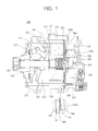
- a variable capacity swash plate-type compressor 100 generally includes a cylinder block 110 that includes a plurality of cylinder bores 112, a suction port 114, and a suction muffler chamber 116; a front housing that is coupled with the cylinder block 110 before the cylinder block 110 to form a crank chamber 122; and a rear housing 130 that is located behind the cylinder block 110 and includes a suction chamber 132, a discharging chamber 134, and a discharging path 136.
- a valve plate 140 is provided between the front housing 120 and the rear housing 130 and a coolant is introduced and discharged through the valve plate 140.
- the valve plate 140 is shaped as a circular plate and includes a plurality of coolant suction openings 140a that are arranged along an outer circular arc and a plurality of coolant discharging openings 140b that are arranged along an inner circular arc.
- a suction reed valve 142 is positioned in front of the valve plate 140 and a discharging reed valve 144 and a retainer 146 are sequentially positioned behind the valve plate 140.
- a one-way valve 150 is provided to prevent a coolant from flowing back to the front of the valve plate 140.
- the variable capacity swash plate-type compressor 100 further includes a driving shaft 160 rotatably provided at the central portion of the cylinder block 110 and the front housing 120; a swash plate 170 connected to a rotor 172 mounted at the driving shaft 160 through a hinge portion 174 in the crank chamber 122 so that its inclined angle varies with the pressure of the crank chamber 122; and a plurality of pistons 180, each interlocking with the swash plate 170 through a shoe 176 and travelling forth and back in the cylinder bore 112 according to the rotation of the swash plate 170, thus sucking and compressing the coolant.
- a compression coil spring 178 is provided between the swash plate 170 and the rotor 172 to return the swash plate 170 to the original position.
- the coolant compressed in the cylinder block 110 is discharged to a condenser through the discharging path 136 and the discharged volume of the coolant may be varied by adjusting the inclined angle of the swash plate 170.
- the swash plate 170 maintains the minimum inclined angle when the air conditioner of the vehicle is turned off, the angle does not become zero degree and thus the coolant is partially discharged from the variable capacity compressor 100 to the condenser even when the air conditioner is turned off.
- the one-way valve 150 is provided at the end of the valve plate 140.
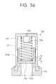
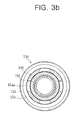
- the conventional one-way valve 150 includes a valve sheet 152 having a coolant inlet 152a formed at the center; a valve case 154 provided over the valve sheet 152 and having a plurality of coolant discharging ports 154a along the circumferential surface; a spool valve 156 selectively opening/closing the coolant inlet 152a and the coolant discharging port 154a in the valve case 154; and a resilient member 158 provided between the valve case 154 and the spool valve 156.
- the valve case 154 includes four coolant discharging ports 154a, one facing another with respect to the central vertical axis of the valve case 154, and a vent hole 154b at the center of the top surface of the valve case 154 to prevent occurrence of back pressure.
- the valve case 154 further includes a guide portion 154c that extends downward from the inner surface of the top portion to guide and support the resilient member 158.
- the spool valve 156 is shaped as a cylindrical structure whose bottom surface is closed and receives the resilient member 158 therein.
- the spool valve 156 is lifted up and down by pressure of the coolant in the valve case 154 to selectively open and close the coolant inlet 152a and the coolant discharging port 154a.
- the conventional one-way valve 150 has a structure in which back pressure exerted by the coolant discharging port 154 right after the coolant discharging port 154a is initially opened is difficult to release through the vent hole 164a provided at the center of the top portion. Furthermore, in the conventional one-way valve 150, a vortex flow generated while back pressure is released through the vent hole 154a caused a valve noise (high-frequency noise).
- a one-way valve of a variable capacity compressor for vehicle may reduce not only low-frequency noises but also high-frequency noises created in the valve when a spool valve initially opens coolant discharging ports.
- a one-way valve of a variable capacity compressor for vehicle including: a valve sheet having a coolant inlet formed at the center; a valve case provided over the valve sheet and having a plurality of coolant discharging ports along the circumferential surface; a spool valve selectively opening/closing the coolant inlet and the coolant discharging port in the valve case; and a resilient member provided between the valve case and the spool valve, wherein the plurality of coolant discharging ports are spaced from each other by a predetermined distance and one of the plurality of coolant discharging ports is closed so that the spool valve is brought in tight contact with an inner wall surface of the valve case when the coolant discharging ports are initially opened not to be swayed left and right.
- Each of the plurality of coolant discharging ports may be shaped as a triangle, a trapezoid, or a quadrangle whose top side is shorter than the bottom side.
- the spool valve may further include a strip portion that is formed along a lower circumferential surface and inclined at a predetermined angle.
- the strip portion of the spool valve may be formed to be adjacent to the Lower end of the coolant discharging port when the spool valve is at its initial position.
- the valve case may include a first vent hole formed at the center of the top surface and a plurality of second vent holes formed around the first vent hole.
- each second vent hole may be relatively larger than that of the first vent hole.
- the resilient member may have a spring constant of about 26gf/mm to about 40gf/mm.
- the spool valve is brought in tight contact with the coolant inlet of the valve case and accordingly not swayed left and right despite the back pressure of the coolant.
- the occurrence of low-frequency noises may be significantly reduced in the valve.
- the one-way valve of a variable capacity compressor for vehicle further includes the strip portion in the spool valve and the spring constant of the resilient member is adapted to be reduced, pressure may be stably maintained in the valve when the valve is opened and closed by the resilient member. Thus, it may be possible to reduce noises created in the valve.
- Fig. 1 is a cross section view illustrating a one-way valve of a variable capacity compressor for vehicle according to the prior art.
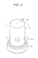
- Fig. 2 is a perspective view illustrating a one-way valve of a variable capacity compressor according to the prior art.
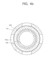
- Figs. 3A and 3B are cross section views taken along lines A-A' and B-B', respectively, of Fig. 2 .
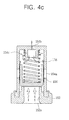
- Figs. 4A to 4C are views illustrating the operation of a spool valve included in a conventional one-way valve.
- Fig. 5 is a perspective view illustrating a one-way valve of a variable capacity compressor according to a first exemplary embodiment of the present invention.
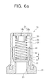
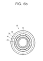
- Figs. 6A and 6B are cross section views taken along lines A-A' and B-B', respectively, of Fig. 4 .
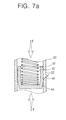
- Figs. 7A to 7C are views illustrating the operation of a spool valve included in the one-way valve according to the first exemplary embodiment of the present invention.
- Fig. 8 is a perspective view illustrating a one-way valve of a variable capacity compressor according to a second exemplary embodiment of the present invention.
- Fig. 9 is a cross section view taken along line A-A' of Fig. 8 .
- Fig. 5 is a perspective view illustrating a one-way valve according to a first exemplary embodiment of the present invention and Figs. 6A and 6B are cross section views taken along lines A-A' and B-B', respectively, of Fig. 4 .
- the one-way valve 10 includes a valve sheet 20 having a coolant inlet 22 formed at its center; a valve case 30 provided over the valve sheet 20 and having a plurality of coolant discharging ports 32 along the circumferential surface; a spool valve 40 selectively opening/closing the coolant inlet 22 and the coolant discharging port 32 in the valve case 30; and a resilient member 50 provided between the valve case 30 and the spool valve 40.
- the valve sheet 20 is provided at a discharging flow path 136 of the compressor 100 shown in Fig. 1 , and includes the coolant inlet 22 therein to allow for inflow of a coolant from the compressor 100.
- valve case 30 further includes a guide portion 36 that extends downward from the inner surface of the top portion to guide and support the resilient member 50. As going downward, the diameter of the guide portion 36 is decreased.
- the valve case 30 is shaped as a cylinder whose top surface is closed, and its lower end is coupled with the upper portion of the valve sheet 20.
- the valve case 30 includes a plurality of coolant discharging ports 32 along the circumferential surface of the valve case 30 and a first vent hole 34a formed at the center of the top surface and a plurality of second vent holes 34b formed around the first vent hole 34a.
- the plurality of coolant discharging ports 32 are spaced from each other by a predetermined distance in a non-uniform manner along the circumferential surface of the valve case 30.
- two of the plurality of coolant discharging ports 32 may face each other and the other may be positioned between the two facing coolant discharging ports 32.
- one coolant discharging port is closed. That is, the three coolant discharging ports 32 are arranged along the circumferential surface of the valve case 30 to be non-uniformly spaced from each other.
- coolant discharging port 32 is shown to be rectangular in Fig. 5 , the coolant discharging port 32 may be shaped as a triangle or a trapezoid whose top side is shorter than the bottom side.
- the reason why the plurality of coolant discharging ports 32 have been non-uniformly arranged on the circumferential surface of the valve case 30 is to prevent the spool valve 40 from being swayed left and right due to back pressure of the coolant immediately before the coolant discharging ports 32 are initially opened, that is, when the pressure P of the coolant is equal to the spring force F of the resilient member.
- Figs. 7A and 7B when lifted up and down, the spool valve 40 is brought in tight contact with the inner wall surface of the valve case 30 where the coolant discharging ports 32 are formed, thus being prevented from being swayed left and right.
- the first vent hole 34a is provided at the center of the top surface of the valve case 30.
- four second vent holes 34b are arranged around the first vent hole 34b and spaced from each other at a predetermined distance.
- the diameter of each second vent hole 34b is relatively larger than that of the first vent hole 34a.
- the second vent hole 34b may be larger in diameter than the first vent hole 34a by about two or three times.
- the first vent hole 34a and the second vent holes 34b as formed at the valve case 30 allow the back pressure generated at the coolant discharging ports 32 immediately after the coolant discharging ports 32 are initially opened to be easily released through the first vent hole 34a and the second vent holes 34b of the valve case 30. Accordingly, a vortex flow may be prevented from occurring and a consequence is a reduction in creation of high-frequency noises.
- the spool valve 40 is configured so that its bottom portion is closed as shown in Fig. 6A , and the resilient member 50 is adapted to be inserted into a receiving portion 42.
- the spool valve 40 includes a strip portion 46 that is formed along the lower circumferential surface and inclined at a predetermined angle.
- the strip portion of the spool valve may be formed to be adjacent to the lower end of the coolant discharging port when the spool valve is at its initial position. That is, the strip portion 46 serves to further reduce the distance l from the lower end of the coolant discharging portion 32 when the spool valve is at its initial position as shown in Fig. 6A than the distance L in the prior art as shown in Fig. 3A to stabilize initial opening pressure.
- the resilient member 50 is provided between the valve case 30 and the spool valve 40 and functions to return the spool valve 40 to its original position when the pressure of the coolant is released.
- the resilient member 50 may have a spring constant of about 26gf/mm to about 40gf/mm.
- a coolant is first introduced into the coolant inlet 22 of the valve sheet 20 and thus spring force F of the resilient member becomes identical to pressure P of the coolant as shown in Figs. 7A and 7B .
- the spool valve 40 is brought in tight contact with the inner wall surface of the valve case 30 where the coolant discharging port 32 is formed.
- the spool valve 40 is not swayed left and right irrespective of occurrence of back pressure of the coolant, thus preventing occurrence of low-frequency noises.
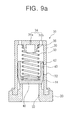
- Fig. 8 is a perspective view illustrating a one-way valve of a variable capacity compressor according to a second exemplary embodiment of the present invention and Fig. 9 is a cross section view taken along line A-A' of Fig. 8 .
- the one-way valve 10 includes a valve sheet 20 having a coolant inlet 22 formed at its center; a valve case 30 provided over the valve sheet 20 and having a plurality of coolant discharging ports 32 along the circumferential surface; a spool valve 40 selectively opening/closing the coolant inlet 22 and the coolant discharging port 32 in the valve case 30; and a resilient member 50 provided between the valve case 30 and the spool valve 40.
- valve sheet 20, the valve case 30, the spool valve 40, and the resilient member 50 are substantially identical to those in the first exemplary embodiment of the present invention except for the number and shape of the coolant discharging port and thus repetitive descriptions will be omitted.
- each coolant discharging port 32 formed at the valve case 30 is shaped as a trapezoid where the top side is shorter than the bottom side.
- the plurality of coolant discharging ports (in this embodiment, for example, five coolant discharging ports) are spaced from each other by a predetermined distance in a non-uniform manner along the circumferential surface of the valve case 30. Among those coolant discharging ports, one is configured to be closed.
- each coolant discharging port 32 is illustrative to have a trapezoidal shape, the shape is not limited, but may be shaped as a triangle or quadrangle whose top side is shorter than the bottom side.
Landscapes
- Engineering & Computer Science (AREA)
- General Engineering & Computer Science (AREA)
- Mechanical Engineering (AREA)
- Compressors, Vaccum Pumps And Other Relevant Systems (AREA)
- Rotary Pumps (AREA)
Applications Claiming Priority (1)
| Application Number | Priority Date | Filing Date | Title |
|---|---|---|---|
| KR1020090044453A KR100915713B1 (ko) | 2009-05-21 | 2009-05-21 | 차량용 가변용량 압축기의 원웨이밸브 |
Publications (3)
| Publication Number | Publication Date |
|---|---|
| EP2256385A2 true EP2256385A2 (de) | 2010-12-01 |
| EP2256385A3 EP2256385A3 (de) | 2013-07-10 |
| EP2256385B1 EP2256385B1 (de) | 2014-09-03 |
Family
ID=41355376
Family Applications (1)
| Application Number | Title | Priority Date | Filing Date |
|---|---|---|---|
| EP20100163466 Not-in-force EP2256385B1 (de) | 2009-05-21 | 2010-05-20 | Einwegventil eines Verdichters mit variabler Leistung für Fahrzeuge |
Country Status (4)
| Country | Link |
|---|---|
| US (1) | US8276613B2 (de) |
| EP (1) | EP2256385B1 (de) |
| KR (1) | KR100915713B1 (de) |
| PT (1) | PT2256385E (de) |
Cited By (3)
| Publication number | Priority date | Publication date | Assignee | Title |
|---|---|---|---|---|
| CN102748452A (zh) * | 2012-07-20 | 2012-10-24 | 广西柳工机械股份有限公司 | 压力保持阀 |
| EP3061969A1 (de) | 2015-02-26 | 2016-08-31 | Comet S.p.A. | Rückschlagventil |
| DE102015101224B4 (de) | 2014-01-30 | 2024-07-25 | Kabushiki Kaisha Toyota Jidoshokki | Sperrventil für einen Verdichter |
Families Citing this family (16)
| Publication number | Priority date | Publication date | Assignee | Title |
|---|---|---|---|---|
| KR100940820B1 (ko) | 2009-09-30 | 2010-02-04 | 동일기계공업 주식회사 | 차량용 가변용량 압축기의 석션밸브 |
| KR101178467B1 (ko) | 2010-12-23 | 2012-09-06 | 동일기계공업 주식회사 | 차량용 압축기의 석션밸브 |
| JP5505377B2 (ja) * | 2011-07-06 | 2014-05-28 | 株式会社デンソー | 正逆リリーフ付電動開閉弁 |
| KR101120841B1 (ko) * | 2012-01-05 | 2012-03-16 | 김기연 | 차량용 가변용량 압축기의 체크밸브 |
| DE102013200417A1 (de) * | 2013-01-14 | 2014-07-31 | Robert Bosch Gmbh | Ventilbaugruppe |
| US9360126B2 (en) * | 2014-04-29 | 2016-06-07 | National Synchrotron Radiation Research Center | Relief valve assembly with anti-frozen shielding hat |
| US10006456B2 (en) * | 2014-08-01 | 2018-06-26 | Murzan, Inc. | Fully-draining diaphragm pump and check valve assembly |
| US10591074B2 (en) * | 2016-07-21 | 2020-03-17 | Hanon Systems | Suction dampening device with internal dampening for vehicle air conditioning compressor |
| KR102671320B1 (ko) * | 2016-08-24 | 2024-06-03 | 한온시스템 주식회사 | 사판식 압축기의 흡입맥동 저감장치 |
| US10156293B1 (en) * | 2017-07-18 | 2018-12-18 | GM Global Technology Operations LLC | Fluid pump pressure relief valve |
| GB201713461D0 (en) * | 2017-08-22 | 2017-10-04 | Cummins Ltd | Valve system |
| CN109720327B (zh) * | 2017-10-20 | 2022-08-02 | 株式会社万都 | 止回阀 |
| DE102019133669B4 (de) * | 2019-12-10 | 2025-06-18 | Schaeffler Technologies AG & Co. KG | Vorrichtung mit einem Bauteil und einem Ventil mit einem Ventilgehäuse des Ventils |
| DE102019133667B4 (de) * | 2019-12-10 | 2025-08-28 | Schaeffler Technologies AG & Co. KG | Vorrichtung zur Regelung von Drücken eines Strömungsmittels mit einem Ventil |
| FR3123954B1 (fr) * | 2021-06-14 | 2026-03-06 | Danfoss Commercial Compressors | Un agencement de soupape de refoulement pour un compresseur frigorifique |
| US20260049655A1 (en) * | 2024-08-13 | 2026-02-19 | Superior Transmission Parts, Inc. | Multi-fit Encapsulated Oscillation Dampener for Automotive Automatic Transmissions |
Family Cites Families (11)
| Publication number | Priority date | Publication date | Assignee | Title |
|---|---|---|---|---|
| US1150743A (en) * | 1913-03-27 | 1915-08-17 | Luke M Johnson | Safety-valve. |
| JP2000055223A (ja) * | 1998-08-07 | 2000-02-22 | Toyota Autom Loom Works Ltd | 差圧制御弁及び圧縮機 |
| JP2000345967A (ja) * | 1999-06-07 | 2000-12-12 | Toyota Autom Loom Works Ltd | 容量可変型圧縮機 |
| JP2000346241A (ja) * | 1999-06-07 | 2000-12-15 | Toyota Autom Loom Works Ltd | 逆止弁 |
| DE20105191U1 (de) * | 2001-03-26 | 2002-05-02 | Honeywell Ag, 63067 Offenbach | Rückflußverhinderer |
| JP4066721B2 (ja) * | 2002-06-17 | 2008-03-26 | 株式会社アドヴィックス | チェック弁及びそのチェック弁を用いたブレーキアクチュエータ |
| JP4329645B2 (ja) * | 2004-08-18 | 2009-09-09 | 株式会社豊田自動織機 | 逆止弁 |
| JP4587778B2 (ja) * | 2004-11-01 | 2010-11-24 | カルソニックカンセイ株式会社 | 吐出側構造及びこれに用いる逆止弁、並びにこれらを用いた圧縮機 |
| JP4583908B2 (ja) * | 2004-12-20 | 2010-11-17 | カルソニックカンセイ株式会社 | 吐出側構造及びこれに用いる逆止弁 |
| JP4429931B2 (ja) * | 2005-02-07 | 2010-03-10 | サンデン株式会社 | 開度調整弁 |
| JP2009103336A (ja) | 2007-10-22 | 2009-05-14 | Tgk Co Ltd | 冷凍サイクル、可変容量圧縮機および吐出弁 |
-
2009
- 2009-05-21 KR KR1020090044453A patent/KR100915713B1/ko active Active
-
2010
- 2010-05-20 PT PT10163466T patent/PT2256385E/pt unknown
- 2010-05-20 EP EP20100163466 patent/EP2256385B1/de not_active Not-in-force
- 2010-05-20 US US12/784,108 patent/US8276613B2/en not_active Expired - Fee Related
Non-Patent Citations (1)
| Title |
|---|
| None |
Cited By (4)
| Publication number | Priority date | Publication date | Assignee | Title |
|---|---|---|---|---|
| CN102748452A (zh) * | 2012-07-20 | 2012-10-24 | 广西柳工机械股份有限公司 | 压力保持阀 |
| CN102748452B (zh) * | 2012-07-20 | 2015-11-11 | 广西柳工机械股份有限公司 | 压力保持阀 |
| DE102015101224B4 (de) | 2014-01-30 | 2024-07-25 | Kabushiki Kaisha Toyota Jidoshokki | Sperrventil für einen Verdichter |
| EP3061969A1 (de) | 2015-02-26 | 2016-08-31 | Comet S.p.A. | Rückschlagventil |
Also Published As
| Publication number | Publication date |
|---|---|
| US20100294972A1 (en) | 2010-11-25 |
| US8276613B2 (en) | 2012-10-02 |
| EP2256385A3 (de) | 2013-07-10 |
| PT2256385E (pt) | 2014-11-05 |
| EP2256385B1 (de) | 2014-09-03 |
| KR100915713B1 (ko) | 2009-09-04 |
Similar Documents
| Publication | Publication Date | Title |
|---|---|---|
| EP2256385A2 (de) | Einwegventil eines Verdichters mit variabler Leistung für Fahrzeuge | |
| EP2362097B1 (de) | Saugventil für Verdichter mit variabler Leistung von Fahrzeugen | |
| CN102124224B (zh) | 斜盘式压缩机的排出止回阀 | |
| EP1039136A3 (de) | Spiralmaschine mit Auslassventil | |
| EP1852607B1 (de) | Taumelscheibenkompressor mit veränderlicher Förderleistung | |
| KR101935805B1 (ko) | 흡입체크밸브 | |
| KR20020062678A (ko) | 용량가변형 압축기의 제어밸브 | |
| EP1298322B1 (de) | Kühlmittelkompressor | |
| US6419467B1 (en) | Structure for suction valve of piston type compressor | |
| US7232294B2 (en) | Compressor having a discharge valve mechanism including a valve retainer having a specially-designed curved surface | |
| EP1394410B1 (de) | Kompressor mit reduzierter Druck Pulsierung | |
| US6748971B2 (en) | Discharge valve assembly of fluid machinery | |
| US20050196291A1 (en) | Piston compressor | |
| JP2005265107A (ja) | 逆止弁 | |
| US20070065299A1 (en) | Compressor | |
| CN221374592U (zh) | 用于压缩机的排气阀组件和压缩机 | |
| JP7511702B2 (ja) | 斜板式コンプレッサー | |
| KR102312403B1 (ko) | 압축기의 흡입 맥동 저감장치 | |
| JP7160001B2 (ja) | ピストン式圧縮機 | |
| JP4642505B2 (ja) | 可変容量斜板式圧縮機の容量制御弁 | |
| JP2004239096A (ja) | 容量可変型圧縮機 | |
| KR101261136B1 (ko) | 압축기 | |
| JP2021032237A (ja) | ピストン式圧縮機 | |
| EP1041284A2 (de) | Einlassventil für Kompressor | |
| JP2009257149A (ja) | 吸入流路変更アダプター |
Legal Events
| Date | Code | Title | Description |
|---|---|---|---|
| PUAI | Public reference made under article 153(3) epc to a published international application that has entered the european phase |
Free format text: ORIGINAL CODE: 0009012 |
|
| 17P | Request for examination filed |
Effective date: 20100608 |
|
| AK | Designated contracting states |
Kind code of ref document: A2 Designated state(s): AL AT BE BG CH CY CZ DE DK EE ES FI FR GB GR HR HU IE IS IT LI LT LU LV MC MK MT NL NO PL PT RO SE SI SK SM TR |
|
| AX | Request for extension of the european patent |
Extension state: BA ME RS |
|
| PUAL | Search report despatched |
Free format text: ORIGINAL CODE: 0009013 |
|
| AK | Designated contracting states |
Kind code of ref document: A3 Designated state(s): AL AT BE BG CH CY CZ DE DK EE ES FI FR GB GR HR HU IE IS IT LI LT LU LV MC MK MT NL NO PL PT RO SE SI SK SM TR |
|
| AX | Request for extension of the european patent |
Extension state: BA ME RS |
|
| RIC1 | Information provided on ipc code assigned before grant |
Ipc: F16K 15/02 20060101AFI20130606BHEP |
|
| GRAP | Despatch of communication of intention to grant a patent |
Free format text: ORIGINAL CODE: EPIDOSNIGR1 |
|
| INTG | Intention to grant announced |
Effective date: 20140325 |
|
| GRAS | Grant fee paid |
Free format text: ORIGINAL CODE: EPIDOSNIGR3 |
|
| GRAA | (expected) grant |
Free format text: ORIGINAL CODE: 0009210 |
|
| AK | Designated contracting states |
Kind code of ref document: B1 Designated state(s): AL AT BE BG CH CY CZ DE DK EE ES FI FR GB GR HR HU IE IS IT LI LT LU LV MC MK MT NL NO PL PT RO SE SI SK SM TR |
|
| REG | Reference to a national code |
Ref country code: GB Ref legal event code: FG4D |
|
| REG | Reference to a national code |
Ref country code: AT Ref legal event code: REF Ref document number: 685805 Country of ref document: AT Kind code of ref document: T Effective date: 20140915 Ref country code: CH Ref legal event code: EP |
|
| REG | Reference to a national code |
Ref country code: IE Ref legal event code: FG4D |
|
| REG | Reference to a national code |
Ref country code: DE Ref legal event code: R096 Ref document number: 602010018659 Country of ref document: DE Effective date: 20141016 |
|
| REG | Reference to a national code |
Ref country code: PT Ref legal event code: SC4A Free format text: AVAILABILITY OF NATIONAL TRANSLATION Effective date: 20141029 |
|
| REG | Reference to a national code |
Ref country code: AT Ref legal event code: MK05 Ref document number: 685805 Country of ref document: AT Kind code of ref document: T Effective date: 20140903 |
|
| PG25 | Lapsed in a contracting state [announced via postgrant information from national office to epo] |
Ref country code: LT Free format text: LAPSE BECAUSE OF FAILURE TO SUBMIT A TRANSLATION OF THE DESCRIPTION OR TO PAY THE FEE WITHIN THE PRESCRIBED TIME-LIMIT Effective date: 20140903 Ref country code: ES Free format text: LAPSE BECAUSE OF FAILURE TO SUBMIT A TRANSLATION OF THE DESCRIPTION OR TO PAY THE FEE WITHIN THE PRESCRIBED TIME-LIMIT Effective date: 20140903 Ref country code: GR Free format text: LAPSE BECAUSE OF FAILURE TO SUBMIT A TRANSLATION OF THE DESCRIPTION OR TO PAY THE FEE WITHIN THE PRESCRIBED TIME-LIMIT Effective date: 20141204 Ref country code: NO Free format text: LAPSE BECAUSE OF FAILURE TO SUBMIT A TRANSLATION OF THE DESCRIPTION OR TO PAY THE FEE WITHIN THE PRESCRIBED TIME-LIMIT Effective date: 20141203 Ref country code: FI Free format text: LAPSE BECAUSE OF FAILURE TO SUBMIT A TRANSLATION OF THE DESCRIPTION OR TO PAY THE FEE WITHIN THE PRESCRIBED TIME-LIMIT Effective date: 20140903 Ref country code: SE Free format text: LAPSE BECAUSE OF FAILURE TO SUBMIT A TRANSLATION OF THE DESCRIPTION OR TO PAY THE FEE WITHIN THE PRESCRIBED TIME-LIMIT Effective date: 20140903 |
|
| REG | Reference to a national code |
Ref country code: NL Ref legal event code: VDEP Effective date: 20140903 |
|
| REG | Reference to a national code |
Ref country code: LT Ref legal event code: MG4D |
|
| PG25 | Lapsed in a contracting state [announced via postgrant information from national office to epo] |
Ref country code: CY Free format text: LAPSE BECAUSE OF FAILURE TO SUBMIT A TRANSLATION OF THE DESCRIPTION OR TO PAY THE FEE WITHIN THE PRESCRIBED TIME-LIMIT Effective date: 20140903 Ref country code: LV Free format text: LAPSE BECAUSE OF FAILURE TO SUBMIT A TRANSLATION OF THE DESCRIPTION OR TO PAY THE FEE WITHIN THE PRESCRIBED TIME-LIMIT Effective date: 20140903 Ref country code: HR Free format text: LAPSE BECAUSE OF FAILURE TO SUBMIT A TRANSLATION OF THE DESCRIPTION OR TO PAY THE FEE WITHIN THE PRESCRIBED TIME-LIMIT Effective date: 20140903 Ref country code: AT Free format text: LAPSE BECAUSE OF FAILURE TO SUBMIT A TRANSLATION OF THE DESCRIPTION OR TO PAY THE FEE WITHIN THE PRESCRIBED TIME-LIMIT Effective date: 20140903 |
|
| PG25 | Lapsed in a contracting state [announced via postgrant information from national office to epo] |
Ref country code: NL Free format text: LAPSE BECAUSE OF FAILURE TO SUBMIT A TRANSLATION OF THE DESCRIPTION OR TO PAY THE FEE WITHIN THE PRESCRIBED TIME-LIMIT Effective date: 20140903 |
|
| PG25 | Lapsed in a contracting state [announced via postgrant information from national office to epo] |
Ref country code: CZ Free format text: LAPSE BECAUSE OF FAILURE TO SUBMIT A TRANSLATION OF THE DESCRIPTION OR TO PAY THE FEE WITHIN THE PRESCRIBED TIME-LIMIT Effective date: 20140903 Ref country code: EE Free format text: LAPSE BECAUSE OF FAILURE TO SUBMIT A TRANSLATION OF THE DESCRIPTION OR TO PAY THE FEE WITHIN THE PRESCRIBED TIME-LIMIT Effective date: 20140903 Ref country code: SK Free format text: LAPSE BECAUSE OF FAILURE TO SUBMIT A TRANSLATION OF THE DESCRIPTION OR TO PAY THE FEE WITHIN THE PRESCRIBED TIME-LIMIT Effective date: 20140903 Ref country code: RO Free format text: LAPSE BECAUSE OF FAILURE TO SUBMIT A TRANSLATION OF THE DESCRIPTION OR TO PAY THE FEE WITHIN THE PRESCRIBED TIME-LIMIT Effective date: 20140903 Ref country code: IS Free format text: LAPSE BECAUSE OF FAILURE TO SUBMIT A TRANSLATION OF THE DESCRIPTION OR TO PAY THE FEE WITHIN THE PRESCRIBED TIME-LIMIT Effective date: 20150103 |
|
| PG25 | Lapsed in a contracting state [announced via postgrant information from national office to epo] |
Ref country code: PL Free format text: LAPSE BECAUSE OF FAILURE TO SUBMIT A TRANSLATION OF THE DESCRIPTION OR TO PAY THE FEE WITHIN THE PRESCRIBED TIME-LIMIT Effective date: 20140903 |
|
| REG | Reference to a national code |
Ref country code: DE Ref legal event code: R097 Ref document number: 602010018659 Country of ref document: DE |
|
| PLBE | No opposition filed within time limit |
Free format text: ORIGINAL CODE: 0009261 |
|
| STAA | Information on the status of an ep patent application or granted ep patent |
Free format text: STATUS: NO OPPOSITION FILED WITHIN TIME LIMIT |
|
| PG25 | Lapsed in a contracting state [announced via postgrant information from national office to epo] |
Ref country code: DK Free format text: LAPSE BECAUSE OF FAILURE TO SUBMIT A TRANSLATION OF THE DESCRIPTION OR TO PAY THE FEE WITHIN THE PRESCRIBED TIME-LIMIT Effective date: 20140903 |
|
| 26N | No opposition filed |
Effective date: 20150604 |
|
| PG25 | Lapsed in a contracting state [announced via postgrant information from national office to epo] |
Ref country code: IT Free format text: LAPSE BECAUSE OF FAILURE TO SUBMIT A TRANSLATION OF THE DESCRIPTION OR TO PAY THE FEE WITHIN THE PRESCRIBED TIME-LIMIT Effective date: 20140903 |
|
| PG25 | Lapsed in a contracting state [announced via postgrant information from national office to epo] |
Ref country code: SI Free format text: LAPSE BECAUSE OF FAILURE TO SUBMIT A TRANSLATION OF THE DESCRIPTION OR TO PAY THE FEE WITHIN THE PRESCRIBED TIME-LIMIT Effective date: 20140903 |
|
| REG | Reference to a national code |
Ref country code: HU Ref legal event code: AG4A Ref document number: E023874 Country of ref document: HU |
|
| REG | Reference to a national code |
Ref country code: DE Ref legal event code: R119 Ref document number: 602010018659 Country of ref document: DE |
|
| REG | Reference to a national code |
Ref country code: CH Ref legal event code: PL |
|
| GBPC | Gb: european patent ceased through non-payment of renewal fee |
Effective date: 20150520 |
|
| PG25 | Lapsed in a contracting state [announced via postgrant information from national office to epo] |
Ref country code: LI Free format text: LAPSE BECAUSE OF NON-PAYMENT OF DUE FEES Effective date: 20150531 Ref country code: LU Free format text: LAPSE BECAUSE OF FAILURE TO SUBMIT A TRANSLATION OF THE DESCRIPTION OR TO PAY THE FEE WITHIN THE PRESCRIBED TIME-LIMIT Effective date: 20150520 Ref country code: CH Free format text: LAPSE BECAUSE OF NON-PAYMENT OF DUE FEES Effective date: 20150531 Ref country code: MC Free format text: LAPSE BECAUSE OF FAILURE TO SUBMIT A TRANSLATION OF THE DESCRIPTION OR TO PAY THE FEE WITHIN THE PRESCRIBED TIME-LIMIT Effective date: 20140903 |
|
| REG | Reference to a national code |
Ref country code: IE Ref legal event code: MM4A |
|
| REG | Reference to a national code |
Ref country code: FR Ref legal event code: ST Effective date: 20160129 |
|
| PG25 | Lapsed in a contracting state [announced via postgrant information from national office to epo] |
Ref country code: IE Free format text: LAPSE BECAUSE OF NON-PAYMENT OF DUE FEES Effective date: 20150520 Ref country code: DE Free format text: LAPSE BECAUSE OF NON-PAYMENT OF DUE FEES Effective date: 20151201 Ref country code: GB Free format text: LAPSE BECAUSE OF NON-PAYMENT OF DUE FEES Effective date: 20150520 |
|
| PG25 | Lapsed in a contracting state [announced via postgrant information from national office to epo] |
Ref country code: FR Free format text: LAPSE BECAUSE OF NON-PAYMENT OF DUE FEES Effective date: 20150601 |
|
| PG25 | Lapsed in a contracting state [announced via postgrant information from national office to epo] |
Ref country code: BE Free format text: LAPSE BECAUSE OF FAILURE TO SUBMIT A TRANSLATION OF THE DESCRIPTION OR TO PAY THE FEE WITHIN THE PRESCRIBED TIME-LIMIT Effective date: 20140903 |
|
| PG25 | Lapsed in a contracting state [announced via postgrant information from national office to epo] |
Ref country code: MT Free format text: LAPSE BECAUSE OF FAILURE TO SUBMIT A TRANSLATION OF THE DESCRIPTION OR TO PAY THE FEE WITHIN THE PRESCRIBED TIME-LIMIT Effective date: 20140903 |
|
| PG25 | Lapsed in a contracting state [announced via postgrant information from national office to epo] |
Ref country code: BG Free format text: LAPSE BECAUSE OF FAILURE TO SUBMIT A TRANSLATION OF THE DESCRIPTION OR TO PAY THE FEE WITHIN THE PRESCRIBED TIME-LIMIT Effective date: 20140903 Ref country code: SM Free format text: LAPSE BECAUSE OF FAILURE TO SUBMIT A TRANSLATION OF THE DESCRIPTION OR TO PAY THE FEE WITHIN THE PRESCRIBED TIME-LIMIT Effective date: 20140903 |
|
| PG25 | Lapsed in a contracting state [announced via postgrant information from national office to epo] |
Ref country code: TR Free format text: LAPSE BECAUSE OF FAILURE TO SUBMIT A TRANSLATION OF THE DESCRIPTION OR TO PAY THE FEE WITHIN THE PRESCRIBED TIME-LIMIT Effective date: 20140903 |
|
| PG25 | Lapsed in a contracting state [announced via postgrant information from national office to epo] |
Ref country code: MK Free format text: LAPSE BECAUSE OF FAILURE TO SUBMIT A TRANSLATION OF THE DESCRIPTION OR TO PAY THE FEE WITHIN THE PRESCRIBED TIME-LIMIT Effective date: 20140903 |
|
| PG25 | Lapsed in a contracting state [announced via postgrant information from national office to epo] |
Ref country code: AL Free format text: LAPSE BECAUSE OF FAILURE TO SUBMIT A TRANSLATION OF THE DESCRIPTION OR TO PAY THE FEE WITHIN THE PRESCRIBED TIME-LIMIT Effective date: 20140903 |
|
| PGFP | Annual fee paid to national office [announced via postgrant information from national office to epo] |
Ref country code: HU Payment date: 20210511 Year of fee payment: 12 |
|
| PGFP | Annual fee paid to national office [announced via postgrant information from national office to epo] |
Ref country code: PT Payment date: 20220519 Year of fee payment: 13 |
|
| PG25 | Lapsed in a contracting state [announced via postgrant information from national office to epo] |
Ref country code: HU Free format text: LAPSE BECAUSE OF NON-PAYMENT OF DUE FEES Effective date: 20220521 |
|
| PG25 | Lapsed in a contracting state [announced via postgrant information from national office to epo] |
Ref country code: PT Free format text: LAPSE BECAUSE OF NON-PAYMENT OF DUE FEES Effective date: 20231120 |