EP1041284A2 - Einlassventil für Kompressor - Google Patents
Einlassventil für Kompressor Download PDFInfo
- Publication number
- EP1041284A2 EP1041284A2 EP00302135A EP00302135A EP1041284A2 EP 1041284 A2 EP1041284 A2 EP 1041284A2 EP 00302135 A EP00302135 A EP 00302135A EP 00302135 A EP00302135 A EP 00302135A EP 1041284 A2 EP1041284 A2 EP 1041284A2
- Authority
- EP
- European Patent Office
- Prior art keywords
- suction
- valve
- reciprocating compressor
- suction port
- discharge
- Prior art date
- Legal status (The legal status is an assumption and is not a legal conclusion. Google has not performed a legal analysis and makes no representation as to the accuracy of the status listed.)
- Withdrawn
Links
- 230000007423 decrease Effects 0.000 description 4
- 238000004378 air conditioning Methods 0.000 description 3
- 239000003507 refrigerant Substances 0.000 description 3
- 239000012530 fluid Substances 0.000 description 2
- 230000010349 pulsation Effects 0.000 description 2
- 238000005452 bending Methods 0.000 description 1
- 230000006835 compression Effects 0.000 description 1
- 238000007906 compression Methods 0.000 description 1
- 238000001816 cooling Methods 0.000 description 1
- 230000006866 deterioration Effects 0.000 description 1
- 239000002184 metal Substances 0.000 description 1
- 230000002093 peripheral effect Effects 0.000 description 1
Images

Classifications
-
- F—MECHANICAL ENGINEERING; LIGHTING; HEATING; WEAPONS; BLASTING
- F04—POSITIVE - DISPLACEMENT MACHINES FOR LIQUIDS; PUMPS FOR LIQUIDS OR ELASTIC FLUIDS
- F04B—POSITIVE-DISPLACEMENT MACHINES FOR LIQUIDS; PUMPS
- F04B39/00—Component parts, details, or accessories, of pumps or pumping systems specially adapted for elastic fluids, not otherwise provided for in, or of interest apart from, groups F04B25/00 - F04B37/00
- F04B39/10—Adaptations or arrangements of distribution members
- F04B39/1073—Adaptations or arrangements of distribution members the members being reed valves
Definitions
- the present invention relates to a reciprocating compressor for compressing a gaseous fluid.
- a conventional compressor for an air conditioning in a car such as a reciprocating compressor, is known (e.g., U.S. Patent No. 4,846,049).
- a discharge valve and a suction valve are disposed on a valve plate, which is held between a cylinder block with a plurality of cylinder bores arranged therein and a cylinder head for closing the outer end of the cylinder block.
- the valve plate has discharge and suction ports corresponding to each cylinder bore.
- the discharge and suction valves close the discharge and suction ports, respectively.
- a piston is inserted in each cylinder bore and driven to reciprocate along the cylinder bore. When the piston reciprocates, the corresponding discharge and suction valves perform opening/closing operations.
- the opening/closing operation of the suction valve is as follows.
- the gas pressure in the cylinder bore lowers.
- the valve opens.
- a cylinder block is provided with a notched step portion corresponding to a tip end of a suction valve.
- the notched step portion forms a stopper restricting the maximum open amount of the suction valve (e.g., JP-Y2 Nos. 35899/1991 and 32881/1978).
- Each of these reciprocating compressors may be used in a car's air conditioning, however, when the in-car cooling load decreases and the refrigerant suction amount decreases, the amount the suction valve opens decreases; thus the suction valve does not abut against the stopper. In such a case, self-exciting vibration is generated in the suction valve, the pulsation of suction gas is increased, and unwanted noise may be generated.
- a reciprocating compressor comprising: a suction port; a suction valve that is movable relative to said suction port for opening or closing said suction port; and a stopper coupled to said suction port for restricting movement of said suction valve, wherein said suction valve is abutted against said stopper to hold open said suction port even when said reciprocating compressor is in a stopped state.
- the reciprocating compressor of the present invention is generally called a swash-plate type variable capacity compressor and is preferably used in an air conditioning system for an automobile or other and other vehicles and similar systems.
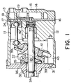
- the reciprocating compressor of the present invention includes a cylinder block 12 having a plurality of arranged cylinder bores (only one is shown) 11, a cylinder head defines a suction chamber 13 and a discharge chamber 14, a valve plate 16 held between the cylinder block 12 and the cylinder head 15, and a plurality of pistons (only one is shown) 17 are inserted in the cylinder bores 11 and reciprocate along the cylinder bores 11 to the left and right.
- the valve plate 16 has a suction port 18 and a discharge port 19 corresponding to each cylinder bore 11.
- the suction port 18 is connected to the suction chamber 13.
- the discharge port 19 is connected to the discharge chamber 14.
- the reciprocating compressor further includes a front housing 31 fixed to the front end surface of the cylinder block 12, a drive shaft 34 rotatably supported by a radial bearing 32 provided in the front housing 31 and by a radial bearing 33 provided in the cylinder block 12, a rotor 36 fixed to the drive shaft 34 and disposed opposite to the front housing 31 via a thrust bearing 35, a swash plate 38 connected to the rotor 36 via a hinge mechanism 37 so that it can be changed in its inclination, and a wobble plate 41 rotatably supported on the swash plate 38 via a bearing 39.
- the swash plate 38 rotates together with the rotor 36 through the hinge mechanism 37, and its inclined angle to the drive shaft 34 is variable.
- the piston 17 is connected to the peripheral part of the wobble plate 41 via a piston rod 42. Additionally, there is provided a guide 43 for preventing the wobble plate 41 from rotating.
- the valve plate 16 has a first surface 16a facing the rear end surface of the cylinder block 12 and a second surface 16b facing the front end surface of the cylinder head 15.
- a suction valve 21 is attached on the first surface 16a of the valve plate 16.
- the suction valve 21 is shown in Fig. 3 and is for opening and closing each suction port 18.
- a discharge valve 22 is attached on the second surface 16b of the valve plate 16.
- the discharge valve 22 has a shape known in the art and is for opening and closing each discharge port 19.
- the suction and the discharge valves 21 and 22 are made of metal plates having elasticity.
- the valve plate 16 is further provided with a retainer 23 for preventing excessive deflection of the discharge valve 22 in a manner known in the art.
- the cylinder block 12 further has a notch portion 24 extending from the rear end surface of the cylinder block 12 and continuous to each cylinder bore 11. A portion of the notch portion 24 forms a stopper 25 that restricts movement of the suction valve 21. Because of the stopper 25, the suction valve 21 is restricted from being opened its maximal amount.
- the suction valve 21 is formed to slightly bend toward the piston 17 beforehand. As a result, the suction valve 21 abuts against the stopper 25 when the compressor is not driven and is in a stop state. Specifically, when there is no force acting on the suction valve 21, the end tip of the suction valve 21 is detached from the first surface 16a of the valve plate 16 and engaged with the stopper 25. On the other hand, the discharge valve 22 extends along the second surface 16b of the valve plate 16 when the compressor is in the stop state.
- the piston 17 reciprocates in the cylinder bore 11.
- a gaseous fluid is compressed in the cylinder bore 11.
- the suction valve 21 is pressed onto the first surface 16a of the valve plate 16 by an increase of gas pressure in the cylinder bore 11 to close the suction port 18.
- the discharge valve 22 opens the discharge port 19 by the gas pressure.
- the discharge valve 22 When the piston 17 moves towards the left direction to carry out a suction stroke, the discharge valve 22 is pressed onto the second surface 16b of the valve plate 16 by gas pressure of the discharge chamber 14 to close the discharge port 19. In this event, the gas pressure lowers in the cylinder bore 11. Therefore, the suction valve 21 opens the suction chamber 18 by a restoring force thereof and negative pressure in the cylinder bore 11.
- the suction valve 21 holds the suction port 18 open during the stop state of the compressor. However, in the operation state of the compressor, the suction valve 21 opens the suction port 18 on the suction stroke and closes the suction port 18 on the discharge stroke. Because the suction valve 21 is slightly bent, while still rigid, and thus acts differently from to a conventional suction valve, the delay in opening the suction valve 21 is reduced. Additionally, even with a low load having a small amount of refrigerant flow, the suction valve 21 is completely opened because it is slightly bent and abuts against the stopper 25 so that self-exciting vibration is prevented.
Landscapes
- Engineering & Computer Science (AREA)
- Mechanical Engineering (AREA)
- General Engineering & Computer Science (AREA)
- Compressor (AREA)
- Compressors, Vaccum Pumps And Other Relevant Systems (AREA)
Applications Claiming Priority (2)
| Application Number | Priority Date | Filing Date | Title |
|---|---|---|---|
| JP11086705A JP2000283042A (ja) | 1999-03-29 | 1999-03-29 | 往復動型圧縮機 |
| JP8670599 | 1999-03-29 |
Publications (2)
| Publication Number | Publication Date |
|---|---|
| EP1041284A2 true EP1041284A2 (de) | 2000-10-04 |
| EP1041284A3 EP1041284A3 (de) | 2001-03-14 |
Family
ID=13894355
Family Applications (1)
| Application Number | Title | Priority Date | Filing Date |
|---|---|---|---|
| EP00302135A Withdrawn EP1041284A3 (de) | 1999-03-29 | 2000-03-16 | Einlassventil für Kompressor |
Country Status (2)
| Country | Link |
|---|---|
| EP (1) | EP1041284A3 (de) |
| JP (1) | JP2000283042A (de) |
Cited By (1)
| Publication number | Priority date | Publication date | Assignee | Title |
|---|---|---|---|---|
| EP1300590A1 (de) * | 2001-10-05 | 2003-04-09 | Carrier Corporation | Saugventil in Lamellenausführung |
Citations (3)
| Publication number | Priority date | Publication date | Assignee | Title |
|---|---|---|---|---|
| JPS5332881A (en) | 1976-09-09 | 1978-03-28 | Mitsubishi Heavy Ind Ltd | Decomposing method of nitrogen compounds |
| US4846049A (en) | 1985-10-11 | 1989-07-11 | Sanden Corporation | Wobble plate type compressor with variable displacement mechanism |
| JPH0335899A (ja) | 1989-06-30 | 1991-02-15 | Komatsu Ltd | 油圧プレスシリンダの同期制御装置 |
Family Cites Families (5)
| Publication number | Priority date | Publication date | Assignee | Title |
|---|---|---|---|---|
| DE3244003A1 (de) * | 1982-11-27 | 1984-05-30 | Robert Bosch Gmbh, 7000 Stuttgart | Verdichter |
| US4642037A (en) * | 1984-03-08 | 1987-02-10 | White Consolidated Industries, Inc. | Reed valve for refrigeration compressor |
| US4976284A (en) * | 1990-01-16 | 1990-12-11 | General Motors Corporation | Reed valve for piston machine |
| BR9002967A (pt) * | 1990-06-19 | 1991-12-24 | Brasil Compressores Sa | Valvula para compressor hermetico de refrigeracao |
| KR0170880B1 (ko) * | 1995-01-28 | 1999-03-30 | 김광호 | 왕복동형 압축기 |
-
1999
- 1999-03-29 JP JP11086705A patent/JP2000283042A/ja not_active Withdrawn
-
2000
- 2000-03-16 EP EP00302135A patent/EP1041284A3/de not_active Withdrawn
Patent Citations (3)
| Publication number | Priority date | Publication date | Assignee | Title |
|---|---|---|---|---|
| JPS5332881A (en) | 1976-09-09 | 1978-03-28 | Mitsubishi Heavy Ind Ltd | Decomposing method of nitrogen compounds |
| US4846049A (en) | 1985-10-11 | 1989-07-11 | Sanden Corporation | Wobble plate type compressor with variable displacement mechanism |
| JPH0335899A (ja) | 1989-06-30 | 1991-02-15 | Komatsu Ltd | 油圧プレスシリンダの同期制御装置 |
Cited By (1)
| Publication number | Priority date | Publication date | Assignee | Title |
|---|---|---|---|---|
| EP1300590A1 (de) * | 2001-10-05 | 2003-04-09 | Carrier Corporation | Saugventil in Lamellenausführung |
Also Published As
| Publication number | Publication date |
|---|---|
| JP2000283042A (ja) | 2000-10-10 |
| EP1041284A3 (de) | 2001-03-14 |
Similar Documents
| Publication | Publication Date | Title |
|---|---|---|
| US5632609A (en) | Valved discharge mechanism of a refrigerant compressor | |
| US5647395A (en) | Valved discharge mechanism of a fluid displacement apparatus | |
| US5607287A (en) | Reciprocating piston type compressor with an improved discharge valve mechanism | |
| US5533871A (en) | Single-headed-piston-type swash-plate compressor having pulsation damping system | |
| EP1586774A1 (de) | Verstellbarer taumelscheibenverdichter für überkritischen kältekreislauf | |
| US5988041A (en) | Piston for compressors | |
| US5562425A (en) | Gas suction structure in piston type compressor | |
| US5249939A (en) | Valved discharge mechanism of a refrigerant compressor | |
| EP0437314A1 (de) | Auslassventil-Mechanismus eines Kühlverdichters | |
| EP1298322B1 (de) | Kühlmittelkompressor | |
| JPH07324678A (ja) | 斜板型圧縮機 | |
| EP0881386B1 (de) | Schiebscheibenverdichter | |
| CA2221475C (en) | Variable displacement compressor | |
| US5842406A (en) | Piston for compressors including a restrictor to prevent the piston from rotating | |
| EP1041284A2 (de) | Einlassventil für Kompressor | |
| US6382939B2 (en) | Reciprocating compressor in which a suction valve is previously bent to open a suction port when the compressor is stopped | |
| EP1004769B1 (de) | Taumelscheibenkompressor mit veränderlicher Förderleistung | |
| CA2181850C (en) | Cylinder assembly for a reciprocating compressor | |
| JP2002070739A (ja) | 往復式冷媒圧縮機 | |
| EP1531266B1 (de) | Kompressor mit veränderlicher Verdrängung | |
| US6368073B1 (en) | Swash plate compressor | |
| US6912948B2 (en) | Swash plate compressor | |
| JP2002031058A (ja) | 往復式冷媒圧縮機 | |
| JP4128656B2 (ja) | 斜板式圧縮機 | |
| US20060222513A1 (en) | Swash plate type variable displacement compressor |
Legal Events
| Date | Code | Title | Description |
|---|---|---|---|
| PUAI | Public reference made under article 153(3) epc to a published international application that has entered the european phase |
Free format text: ORIGINAL CODE: 0009012 |
|
| AK | Designated contracting states |
Kind code of ref document: A2 Designated state(s): AT BE CH CY DE DK ES FI FR GB GR IE IT LI LU MC NL PT SE |
|
| AX | Request for extension of the european patent |
Free format text: AL;LT;LV;MK;RO;SI |
|
| PUAL | Search report despatched |
Free format text: ORIGINAL CODE: 0009013 |
|
| AK | Designated contracting states |
Kind code of ref document: A3 Designated state(s): AT BE CH CY DE DK ES FI FR GB GR IE IT LI LU MC NL PT SE |
|
| AX | Request for extension of the european patent |
Free format text: AL;LT;LV;MK;RO;SI |
|
| AKX | Designation fees paid | ||
| STAA | Information on the status of an ep patent application or granted ep patent |
Free format text: STATUS: THE APPLICATION IS DEEMED TO BE WITHDRAWN |
|
| 18D | Application deemed to be withdrawn |
Effective date: 20010915 |
|
| REG | Reference to a national code |
Ref country code: DE Ref legal event code: 8566 |