EP2256268B1 - Fall arrest safety net - Google Patents
Fall arrest safety net Download PDFInfo
- Publication number
- EP2256268B1 EP2256268B1 EP10250921.3A EP10250921A EP2256268B1 EP 2256268 B1 EP2256268 B1 EP 2256268B1 EP 10250921 A EP10250921 A EP 10250921A EP 2256268 B1 EP2256268 B1 EP 2256268B1
- Authority
- EP
- European Patent Office
- Prior art keywords
- line
- safety net
- eyes
- fall arrest
- mouth
- Prior art date
- Legal status (The legal status is an assumption and is not a legal conclusion. Google has not performed a legal analysis and makes no representation as to the accuracy of the status listed.)
- Active
Links
Images


Classifications
-
- E—FIXED CONSTRUCTIONS
- E04—BUILDING
- E04G—SCAFFOLDING; FORMS; SHUTTERING; BUILDING IMPLEMENTS OR AIDS, OR THEIR USE; HANDLING BUILDING MATERIALS ON THE SITE; REPAIRING, BREAKING-UP OR OTHER WORK ON EXISTING BUILDINGS
- E04G21/00—Preparing, conveying, or working-up building materials or building elements in situ; Other devices or measures for constructional work
- E04G21/32—Safety or protective measures for persons during the construction of buildings
- E04G21/3261—Safety-nets; Safety mattresses; Arrangements on buildings for connecting safety-lines
- E04G21/3266—Safety nets
-
- E—FIXED CONSTRUCTIONS
- E04—BUILDING
- E04G—SCAFFOLDING; FORMS; SHUTTERING; BUILDING IMPLEMENTS OR AIDS, OR THEIR USE; HANDLING BUILDING MATERIALS ON THE SITE; REPAIRING, BREAKING-UP OR OTHER WORK ON EXISTING BUILDINGS
- E04G21/00—Preparing, conveying, or working-up building materials or building elements in situ; Other devices or measures for constructional work
- E04G21/32—Safety or protective measures for persons during the construction of buildings
- E04G21/3261—Safety-nets; Safety mattresses; Arrangements on buildings for connecting safety-lines
- E04G21/3276—Arrangements on buildings for connecting safety-lines
- E04G21/329—Arrangements on buildings for connecting safety-lines with measures for dampening the fall
Definitions
- the present invention relates to a safety net having an attachment device for securing to a construction element particularly for use as a fall arrest apparatus.
- a safety apparatus When working at elevated positions, in order to protect anyone below the working position, a safety apparatus should be provided to arrest a fall of debris.
- a safety net may be suspended just below the working height and fastened, for example, to free standing columns or to end-securing fixtures mounted to a wall.
- US3527319 describes a rectangular safety net with a plurality of eyes integral with the net, and spaced about its periphery.
- a line has opposing first and second ends, first and second line portions of the line being disposed adjacent the first and second ends respectively, and an intermediate portion of the line is located between the first and second line portions.
- the line may extend through the eyes in a ring to support the periphery of the net.
- a safety net assembly comprising: a bag constructed of wire mesh, the bag having an open mouth, the bag including a plurality of eyes integral with the wire mesh and spaced circumferentially about the mouth; an elongate line having opposing first and second ends, first and second line portions of the line being disposed adjacent the first and second ends respectively, an intermediate portion of the line located between the first and second line portions, and a choker fitting having two faces; a plurality openings in the choker fitting which extend between the two faces, an end-securing fixture on the choker fitting, the first portion of the line extending through the eyes for drawing the mouth closed, and wherein either:
- the first portion of the line provides an elongate flexible member, and while the first portion of the line may be continuous, it may alternatively be interrupted by fasteners, links, or the like, connected to adjacent ends of the line and which can be separated so that the ring may be broken as needed in some installations of the net (which are discussed below).
- the intermediate portion extends through the openings in the choker fitting so that a loop in the line protrudes from each of the faces of the choker fitting, each loop spanning between two of the openings.
- two openings will be sufficient for connection in this manner, however most preferably the openings include three openings through which the line passes sequentially, the loops being connected through one of the openings.
- the line further comprises a terminal eye formed on the second end of the line.
- the assembly preferably further comprises a hook fastener received in the terminal eye.
- the two faces of the choker fitting comprise opposing faces of a planar part of the choker fitting
- the end-securing fixture comprising a line-receiving aperture having an axis disposed in the plane of the planar part and the first end of the line includes an end-securing fixture thereon, whereby the first portion is received in the line-receiving aperture and the end-securing fixture is sized so as not to pass through the line-receiving aperture.
- the wire mesh bag is formed from a length of wire with fastenings joining portions of the length of wire, the length of wire extending from the closed end toward the mouth and being turned back upon itself to form the eyes at the mouth and corresponding eyes at the closed end, each eye at the mouth being fixed by a respective one of said fastenings to the adjacent eye on either side thereof, and each eye at the closed end being fixed by a respective one of said fastenings to the adjacent eye on either side thereof to form the bag.
- the fastenings that join two portions of the length of wire and are preferably all of like type, most preferably being ferrules which are crimped or moulded in place.
- the fastenings joining the eyes at the closed end are more closely spaced along the length of wire than the fastenings joining the eyes at the mouth.
- the invention provides a method of securing apparatus mounted overhead upon a construction member, the method comprising:
- This invention provides a safety net assembly which is effective and efficient in operational use, providing for ready installation and removal as needed.
- the net has an overall simple design which minimizes manufacturing costs and maximizes performance.
- a fall arrest net can be required to absorb significant energy in use, and it has been found that this design offers an ability to spread impact loads.
- the loops formed about the mouth of the bag provide a degree of movement and avoid highly localised loading stress raisers.
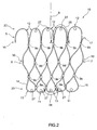
- a first embodiment of a safety net assembly includes a bag 1 having a narrow closed end 2 and a broader opposing open mouth 3 in which an opening 4 is provided for receiving an apparatus to be secured, such as a light fitting 50 (shown in Fig. 7 ) mounted overhead on a member such as a beam 51.
- a line 33 passes in a ring through the eyes 12 of the mouth 3 and cooperates with a choker fitting 52 to draw together the eyes 12 to close the opening 4.
- An end of the line 33 is looped around the beam 51 to secure the assembly in place.
- the mesh may be made from a length of wire 5 which may be continuous (i.e. a single length) or discontinuous (for instance, including end-to-end joints) and which provides a degree of flexibility and resilience to the bag 1, allowing it to be expanded in a direction transverse to the lay of the wire so as to accommodate apparatus of varying size, while being readily collapsible.
- the bag 1 is made from a panel of mesh 10, shown in Fig. 2 , which is curved or folded about a longitudinal axis 8; the transversely opposing edges 6, 7 of the mesh 10 are then joined to produce the substantially tapered bag-like form (shown in Fig 1 in its collapsed or relaxed state).
- the mesh 10 is a non-woven type in which portions of the length of wire 5 are joined by fastenings in the form of ferrules 9a, 9b, 9c, 9d at nodes of the mesh.
- the length of wire 5 extends generally longitudinally and is turned back upon itself and joined by ferrules 9c to form eyes 11 at the first edge 23 of the mesh 10, and by ferrules 9d to form the eyes 12 at the longitudinally opposing second edge 22 of the mesh 10.
- Fastenings in the form of ferrules 9b join the adjacent eyes 12 along the second edge 22 and ferrules 9a join the adjacent eyes 11 along the along the first edge 23.
- the mesh 10 may be conveniently manufactured by winding the length of wire 5 between pegs 27 spaced apart in two parallel lines, the lines being spaced apart in the longitudinal direction (relative to the mesh 10).
- the length of wire 5 is wound about the pegs in a zigzag pattern, alternating in direction when it is turned back upon itself around each peg 27.
- the mesh 10 is removed from the pegs 27 curved about the longitudinal axis 8.
- Portions 14 and 15 of the outermost first edge eyes 11 are then joined by a ferrule (not shown) such that each eye 11 is fixed by a ferrule to the adjacent eye on either side thereof.
- the ends 16, 17 of the length of wire 5 are joined by a ferrule (not shown) such that each eye 12 along the second edge 22 is fixed by a ferrule to the adjacent eye on either side thereof.
- a further ferrule joins portions 18 and 19 on opposing transverse edges of the mesh 10 to form the substantially axisymmetrical bag 1.
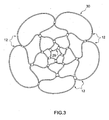
- all the eyes 11 are joined in a first ring 29 to form a closed end of the bag 1.
- All the eyes 12 are joined in a second ring 30 which forms the opening 4.
- the transverse dimension of the second edge 22 exceeds that of the first edge 23.
- the eyes 12 are larger than the eyes 11 and the ferrules 9a joining the eyes 11 are spaced more closely apart (by dimension 24 measured along the length of wire 5) than the ferrules 9b joining the eyes 12 on the second edge 22 (which are spaced by dimension 25 measured along the length of wire 5).
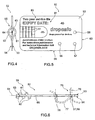
- a first embodiment of the choker fitting 52 may be formed from a substantially rectangular stainless steel sheet having opposing faces 53, 54.
- an end-securing fixture 55 which defines a line-receiving aperture 63, while on the opposite side are three circular openings 56, 57, 58 sized to receive the line 33.
- the opening 57 may be proximate a corner of the sheet, with the openings 56, 58 spaced at the same radial distance from opening 57 and at the same distance from their respective orthogonal edges 59, 60.
- the end-securing fixture 55 Formed in the choker fitting 52, as by a slitting/pressing operation, the end-securing fixture 55 includes integral U-shaped arms 61, 62 projecting either side from faces 53, 54 and thereby spanning and defining the aperture 63. Formed in this manner the aperture 63 has an axis 64 disposed in the plane of the planar member. Adjacent the innermost arm 62 is a through-extending aperture 65 which is substantially D-shaped.
- textual indicia 80 including an "Expiry date" marking 81 located adjacent a blank area 82 where a date can be permanently marked, by engraving, etching, stamping or the like, to notify users of the end of the working life of the product.
- the line 33 has a first end 70 adjacent to which a bead-shaped ferrule or like fitting 71 is fixed.
- the fitting 71 is disposed in the aperture 65, while the first end 70 extends through the line-receiving aperture 63, the end-securing fixture being larger than the aperture 63 so as to thereby fix the first end the choker fitting 52.
- a second end 72 of the line 33 opposing the first end 70 includes a terminal eye 73 formed as by an eye splice or by a loop fixed by a ferrule, or like fastener.
- a first portion 74 of the line 33 adjacent the first terminal end 70 extends from the end-securing fixture 55 in a ring through the eyes 12 for drawing the mouth 3 closed.
- a second portion 78 of the line 33 extends from the choker fitting 52 to the second end 72.
- An intermediate portion 75 of the line 33 is located between the first and second line portions 74, 78, and passes sequentially through the openings 56, 57 and 58 in the choker fitting. As shown in dashed outline in Fig. 6 , a first loop 76 of the line extends through the openings 57, 58 to protrude from of the face 53, while a second like loop 77 extending between openings 56 and 57 protrudes from the opposing face 54.
- the line 3 and the length of wire 5 may be twisted stainless steel wire cables for corrosion resistance.
- the other components, such as the ferrules 9a, 9b, 9c, 9d and the hook fastener are also formed of stainless steel.
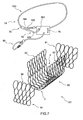
- Fig. 7 shows an exploded view of a second embodiment of the safety net assembly, wherein the bag 101 is assembled from a folded main panel 90 and two like end panels 91.
- the panels 90, 91 are each formed of a flexible wire mesh, and may each be formed initially each from a respective single length of wire joined at nodes of the mesh by ferrules, or moulded beads etc.
- the main panel 90 is a rectangular panel folded in a curve and includes rows of eyes 92, 93 along longitudinally opposite transverse edges which, when the panel 90 is folded in a curve as shown are brought together to form opposing sides of the mouth 4, the curved central section of panel 90 forming the closed end 2.
- the panels 91 have a row of eyes 94 along one edge and are shaped with an arcuate opposing edge complementary to the form of the panel 90.
- Each end panels 90 is fixed about its peripheral edge, as by ferules or the like, to a long edge of the panel 91, such that the rows of eyes 92, 93, 94 are generally coplanar, the eyes being spaced about the periphery of the mouth 4.
- the line 133 and choker 152 shown in Fig. 7 are generally like that of the first embodiment, but with a differing connection between the terminal end 70 of first line portion 74 and the choker 152.
- a fastener 120 such as a hook fastener, or carabiner with a spring-closed gate, is fixed to the end of the first line section 74, as by a permanent eye 164 formed on the end 70.
- the wire comprising the eye 164 may pass through an aperture formed in the fastener 12, as shown such that the fastener is permanently fixed to the line.
- a circular aperture 163 extends between the opposing sides of the choker 152.
- the fastener 120 is received in the aperture 163 which thus provides the end-securing fixture in this embodiment.
- the line 33 passes from the choker fitting 152 through the eyes 92, 93, 94 and back to the choker fitting 152, for drawing the mouth 3 of the bag 101 closed.
- a third embodiment of the invention is shown in Fig. 8 and includes panels 90, 91, 111 each formed from a flexible wire mesh.
- the panels 111 like the panels 91 the second embodiment, have a row of eyes 94 along one edge and are shaped with an arcuate opposing edge complementary to the form of the panel 90.
- the panel 111 further includes a slit 112 in the fabric of the mesh (where adjacent wire loops are disconnected). The slit 112 extends longitudinally down from the row of eyes 94 to an intermediate position in the panel.
- the end panel 111 is otherwise of like construction to the panels 91 and is fixed about its peripheral edge to a long edge of the panel 91, in like manner to the second embodiment.
- the line 33 and choker 52 of the third embodiment are generally like that of the first embodiment, but the ring-shaped first portion 74 has a fastener 110 connected in the line 33, allowing the ring to be opened and closed.
- the fastener 110 may be a carabiner joining permanent eyes formed in the first portion 74.
- the net of the invention is formed from a single generally rectangular panel of flexible wire mesh.
- a folded central part of the panel forms the closed end 2 and the opposing short edges of the panel bound the periphery of the open mouth 3, the line 33 passing from the choker fitting 52 through the eyes 92, 93 and back to the choker fitting 52, for drawing the mouth 3 closed.
- the two halves of the long edge on one side of the panel are connected by join line 115.
- the two halves 116, 117 of the opposing long edge of the panel are not joined, and define a slit 112 extending from the mouth 3 down one side of the bag toward the closed end 2, in like manner to the third embodiment of Fig. 8 .
- the components of the light fitting 50 are first introduced through the open mouth 3 thereby substantially enclosing the light fitting in the bag 1.
- the choker fitting By then manipulating the choker fitting to draw the line through the openings 56, 57, 58 the ring-shaped first line portion 74 is reduced in size to close the mouth 3.
- the second portion 78 of the line 33 is then looped about the construction member 51.
- a hook fastener 88 (such as a carabiner having a hinged gate and screw closure) is inserted through the terminal eye 73 and through the ring-shaped first line portion 74 to secure the assembly.
- a member 113 such as the power cable shown in phantom in Figs.
- the fastener 110 is positioned proximate the slit 112 and opened to break open the ring and allow entry of the member 113 into the slit 112. By reconnecting the fastener 110, the mouth can then be drawn closed, to the same degree as the second embodiment, substantially enclosing the light fitting 50.
Landscapes
- Engineering & Computer Science (AREA)
- Architecture (AREA)
- Mechanical Engineering (AREA)
- Civil Engineering (AREA)
- Structural Engineering (AREA)
- Emergency Lowering Means (AREA)
Priority Applications (1)
| Application Number | Priority Date | Filing Date | Title |
|---|---|---|---|
| PL10250921T PL2256268T3 (pl) | 2009-05-13 | 2010-05-13 | Siatka bezpieczeństwa zatrzymująca spadanie |
Applications Claiming Priority (1)
| Application Number | Priority Date | Filing Date | Title |
|---|---|---|---|
| AU2009902117A AU2009902117A0 (en) | 2009-05-13 | Fall Arrest Safety Net |
Publications (3)
| Publication Number | Publication Date |
|---|---|
| EP2256268A2 EP2256268A2 (en) | 2010-12-01 |
| EP2256268A3 EP2256268A3 (en) | 2012-01-04 |
| EP2256268B1 true EP2256268B1 (en) | 2014-07-30 |
Family
ID=42671631
Family Applications (1)
| Application Number | Title | Priority Date | Filing Date |
|---|---|---|---|
| EP10250921.3A Active EP2256268B1 (en) | 2009-05-13 | 2010-05-13 | Fall arrest safety net |
Country Status (6)
| Country | Link |
|---|---|
| EP (1) | EP2256268B1 (pl) |
| CN (1) | CN101906881B (pl) |
| AU (1) | AU2010201930B2 (pl) |
| DK (1) | DK2256268T3 (pl) |
| PL (1) | PL2256268T3 (pl) |
| SG (1) | SG169926A1 (pl) |
Cited By (1)
| Publication number | Priority date | Publication date | Assignee | Title |
|---|---|---|---|---|
| WO2022218116A1 (en) | 2021-04-15 | 2022-10-20 | Mrm Hk Limited | Fall arrest safety net |
Families Citing this family (2)
| Publication number | Priority date | Publication date | Assignee | Title |
|---|---|---|---|---|
| US9446883B2 (en) | 2009-07-16 | 2016-09-20 | Mrm Hk Limited | Fall arrest safety net |
| CN108086790B (zh) * | 2016-11-23 | 2020-05-12 | Mrm香港有限公司 | 紧固件组件、网格面板和屏障系统 |
Family Cites Families (9)
| Publication number | Priority date | Publication date | Assignee | Title |
|---|---|---|---|---|
| US3527319A (en) * | 1969-08-15 | 1970-09-08 | Pedley Knowles & Co | Safety net |
| JP2679572B2 (ja) * | 1993-05-14 | 1997-11-19 | 鹿島建設株式会社 | カーテン式安全ネット |
| CN2234479Y (zh) * | 1995-03-06 | 1996-09-04 | 烟台华庆塑料制品有限公司 | 建筑安全立网 |
| CN2298302Y (zh) * | 1997-03-12 | 1998-11-25 | 燕和工业股份有限公司 | 建筑网 |
| JPH10339038A (ja) * | 1997-06-09 | 1998-12-22 | Taisei Corp | 外壁pcカーテンウォール用安全垂直ネットの取付方法 |
| AT409283B (de) * | 2000-06-09 | 2002-07-25 | Hasler Josef | Auffangvorrichtung für fallende personen oder gegenstände |
| DE20217248U1 (de) * | 2002-11-08 | 2003-02-06 | Söhring, Karl-Heinz, 46286 Dorsten | Schutznetz zum Auffangen von abstürzenden Personen und/oder Gegenständen bei Bau- und/oder Montagearbeiten |
| DE202006015087U1 (de) * | 2006-09-30 | 2006-12-21 | Reinhardt, Thomas | Faltdämpfer |
| CN201050197Y (zh) * | 2007-06-15 | 2008-04-23 | 王喜 | 建筑安全网用紧固件 |
-
2010
- 2010-05-13 PL PL10250921T patent/PL2256268T3/pl unknown
- 2010-05-13 EP EP10250921.3A patent/EP2256268B1/en active Active
- 2010-05-13 AU AU2010201930A patent/AU2010201930B2/en active Active
- 2010-05-13 SG SG201003409-8A patent/SG169926A1/en unknown
- 2010-05-13 DK DK10250921.3T patent/DK2256268T3/da active
- 2010-05-13 CN CN201010227888.4A patent/CN101906881B/zh active Active
Cited By (1)
| Publication number | Priority date | Publication date | Assignee | Title |
|---|---|---|---|---|
| WO2022218116A1 (en) | 2021-04-15 | 2022-10-20 | Mrm Hk Limited | Fall arrest safety net |
Also Published As
| Publication number | Publication date |
|---|---|
| EP2256268A2 (en) | 2010-12-01 |
| DK2256268T3 (da) | 2014-11-10 |
| CN101906881B (zh) | 2014-08-27 |
| AU2010201930B2 (en) | 2016-12-15 |
| SG169926A1 (en) | 2011-04-29 |
| AU2010201930A1 (en) | 2010-12-02 |
| PL2256268T3 (pl) | 2015-11-30 |
| EP2256268A3 (en) | 2012-01-04 |
| CN101906881A (zh) | 2010-12-08 |
Similar Documents
| Publication | Publication Date | Title |
|---|---|---|
| US9446883B2 (en) | Fall arrest safety net | |
| US5848665A (en) | Safety/debris net system | |
| WO1999058790A1 (en) | Adjustable safety net methods and apparatus | |
| EP2256268B1 (en) | Fall arrest safety net | |
| KR101596783B1 (ko) | 사이드 보호 시스템 | |
| US8714308B2 (en) | Fall arrest safety net | |
| US10458146B2 (en) | Wire barrier | |
| US6161648A (en) | Safety/debris net system | |
| KR101616204B1 (ko) | 케이블 지지용 행거 | |
| US5404998A (en) | Wire conveyor belt with closed edges and method of making same | |
| WO2010074445A2 (ko) | 감기는 것이 가능한 철망 보강구조 | |
| US20090057637A1 (en) | Mounting Straps for Barriers | |
| US12510133B2 (en) | Fall arrest safety net | |
| JP2020125634A (ja) | ネット用ロープクリップおよびロープとネットの結合構造 | |
| CN216304864U (zh) | 检查井防坠落装置 | |
| JP2014058791A (ja) | 区画ネット | |
| KR20120112279A (ko) | 연등 고리 및 이를 포함하는 연등 | |
| KR100407129B1 (ko) | 분할 및 개폐식 방조망 설치구조 | |
| JP2019052478A (ja) | 車両固縛システム | |
| JP3204055U (ja) | 接合バックル | |
| KR20250078411A (ko) | 비너가 있는 지중송전 장비반입 전용 안전가이드 구조체 | |
| KR100899065B1 (ko) | 체인 연결용 고리 | |
| NZ532304A (en) | Fence straining apparatus | |
| GB2376975A (en) | Safety net support | |
| JPH0650004A (ja) | 防護用ネット,シートの連結具 |
Legal Events
| Date | Code | Title | Description |
|---|---|---|---|
| PUAI | Public reference made under article 153(3) epc to a published international application that has entered the european phase |
Free format text: ORIGINAL CODE: 0009012 |
|
| AK | Designated contracting states |
Kind code of ref document: A2 Designated state(s): AL AT BE BG CH CY CZ DE DK EE ES FI FR GB GR HR HU IE IS IT LI LT LU LV MC MK MT NL NO PL PT RO SE SI SK SM TR |
|
| AX | Request for extension of the european patent |
Extension state: BA ME RS |
|
| PUAL | Search report despatched |
Free format text: ORIGINAL CODE: 0009013 |
|
| AK | Designated contracting states |
Kind code of ref document: A3 Designated state(s): AL AT BE BG CH CY CZ DE DK EE ES FI FR GB GR HR HU IE IS IT LI LT LU LV MC MK MT NL NO PL PT RO SE SI SK SM TR |
|
| AX | Request for extension of the european patent |
Extension state: BA ME RS |
|
| RIC1 | Information provided on ipc code assigned before grant |
Ipc: E04G 21/32 20060101AFI20111130BHEP |
|
| 17P | Request for examination filed |
Effective date: 20120627 |
|
| GRAP | Despatch of communication of intention to grant a patent |
Free format text: ORIGINAL CODE: EPIDOSNIGR1 |
|
| INTG | Intention to grant announced |
Effective date: 20140224 |
|
| GRAS | Grant fee paid |
Free format text: ORIGINAL CODE: EPIDOSNIGR3 |
|
| GRAA | (expected) grant |
Free format text: ORIGINAL CODE: 0009210 |
|
| AK | Designated contracting states |
Kind code of ref document: B1 Designated state(s): AL AT BE BG CH CY CZ DE DK EE ES FI FR GB GR HR HU IE IS IT LI LT LU LV MC MK MT NL NO PL PT RO SE SI SK SM TR |
|
| REG | Reference to a national code |
Ref country code: GB Ref legal event code: FG4D |
|
| REG | Reference to a national code |
Ref country code: CH Ref legal event code: EP |
|
| REG | Reference to a national code |
Ref country code: AT Ref legal event code: REF Ref document number: 680092 Country of ref document: AT Kind code of ref document: T Effective date: 20140815 |
|
| REG | Reference to a national code |
Ref country code: IE Ref legal event code: FG4D |
|
| REG | Reference to a national code |
Ref country code: DE Ref legal event code: R096 Ref document number: 602010017866 Country of ref document: DE Effective date: 20140911 |
|
| RAP2 | Party data changed (patent owner data changed or rights of a patent transferred) |
Owner name: MRM HK LIMITED |
|
| REG | Reference to a national code |
Ref country code: DK Ref legal event code: T3 Effective date: 20141104 |
|
| REG | Reference to a national code |
Ref country code: DE Ref legal event code: R082 Ref document number: 602010017866 Country of ref document: DE Representative=s name: MARKS & CLERK (LUXEMBOURG) LLP, LU |
|
| REG | Reference to a national code |
Ref country code: NL Ref legal event code: T3 |
|
| REG | Reference to a national code |
Ref country code: NO Ref legal event code: T2 Effective date: 20140730 |
|
| REG | Reference to a national code |
Ref country code: AT Ref legal event code: MK05 Ref document number: 680092 Country of ref document: AT Kind code of ref document: T Effective date: 20140730 |
|
| REG | Reference to a national code |
Ref country code: DE Ref legal event code: R082 Ref document number: 602010017866 Country of ref document: DE Representative=s name: MARKS & CLERK (LUXEMBOURG) LLP, LU Effective date: 20141117 Ref country code: DE Ref legal event code: R081 Ref document number: 602010017866 Country of ref document: DE Owner name: MRM HK LIMITED, HK Free format text: FORMER OWNER: MRM HOLDINGS LTD., PORT LOUIS, MU Effective date: 20141117 |
|
| REG | Reference to a national code |
Ref country code: LT Ref legal event code: MG4D |
|
| PG25 | Lapsed in a contracting state [announced via postgrant information from national office to epo] |
Ref country code: LT Free format text: LAPSE BECAUSE OF FAILURE TO SUBMIT A TRANSLATION OF THE DESCRIPTION OR TO PAY THE FEE WITHIN THE PRESCRIBED TIME-LIMIT Effective date: 20140730 Ref country code: ES Free format text: LAPSE BECAUSE OF FAILURE TO SUBMIT A TRANSLATION OF THE DESCRIPTION OR TO PAY THE FEE WITHIN THE PRESCRIBED TIME-LIMIT Effective date: 20140730 Ref country code: PT Free format text: LAPSE BECAUSE OF FAILURE TO SUBMIT A TRANSLATION OF THE DESCRIPTION OR TO PAY THE FEE WITHIN THE PRESCRIBED TIME-LIMIT Effective date: 20141202 Ref country code: FI Free format text: LAPSE BECAUSE OF FAILURE TO SUBMIT A TRANSLATION OF THE DESCRIPTION OR TO PAY THE FEE WITHIN THE PRESCRIBED TIME-LIMIT Effective date: 20140730 Ref country code: GR Free format text: LAPSE BECAUSE OF FAILURE TO SUBMIT A TRANSLATION OF THE DESCRIPTION OR TO PAY THE FEE WITHIN THE PRESCRIBED TIME-LIMIT Effective date: 20141031 Ref country code: BG Free format text: LAPSE BECAUSE OF FAILURE TO SUBMIT A TRANSLATION OF THE DESCRIPTION OR TO PAY THE FEE WITHIN THE PRESCRIBED TIME-LIMIT Effective date: 20141030 Ref country code: SE Free format text: LAPSE BECAUSE OF FAILURE TO SUBMIT A TRANSLATION OF THE DESCRIPTION OR TO PAY THE FEE WITHIN THE PRESCRIBED TIME-LIMIT Effective date: 20140730 |
|
| PG25 | Lapsed in a contracting state [announced via postgrant information from national office to epo] |
Ref country code: CY Free format text: LAPSE BECAUSE OF FAILURE TO SUBMIT A TRANSLATION OF THE DESCRIPTION OR TO PAY THE FEE WITHIN THE PRESCRIBED TIME-LIMIT Effective date: 20140730 Ref country code: HR Free format text: LAPSE BECAUSE OF FAILURE TO SUBMIT A TRANSLATION OF THE DESCRIPTION OR TO PAY THE FEE WITHIN THE PRESCRIBED TIME-LIMIT Effective date: 20140730 Ref country code: LV Free format text: LAPSE BECAUSE OF FAILURE TO SUBMIT A TRANSLATION OF THE DESCRIPTION OR TO PAY THE FEE WITHIN THE PRESCRIBED TIME-LIMIT Effective date: 20140730 Ref country code: IS Free format text: LAPSE BECAUSE OF FAILURE TO SUBMIT A TRANSLATION OF THE DESCRIPTION OR TO PAY THE FEE WITHIN THE PRESCRIBED TIME-LIMIT Effective date: 20141130 Ref country code: AT Free format text: LAPSE BECAUSE OF FAILURE TO SUBMIT A TRANSLATION OF THE DESCRIPTION OR TO PAY THE FEE WITHIN THE PRESCRIBED TIME-LIMIT Effective date: 20140730 |
|
| PG25 | Lapsed in a contracting state [announced via postgrant information from national office to epo] |
Ref country code: RO Free format text: LAPSE BECAUSE OF FAILURE TO SUBMIT A TRANSLATION OF THE DESCRIPTION OR TO PAY THE FEE WITHIN THE PRESCRIBED TIME-LIMIT Effective date: 20140730 Ref country code: EE Free format text: LAPSE BECAUSE OF FAILURE TO SUBMIT A TRANSLATION OF THE DESCRIPTION OR TO PAY THE FEE WITHIN THE PRESCRIBED TIME-LIMIT Effective date: 20140730 Ref country code: CZ Free format text: LAPSE BECAUSE OF FAILURE TO SUBMIT A TRANSLATION OF THE DESCRIPTION OR TO PAY THE FEE WITHIN THE PRESCRIBED TIME-LIMIT Effective date: 20140730 Ref country code: SK Free format text: LAPSE BECAUSE OF FAILURE TO SUBMIT A TRANSLATION OF THE DESCRIPTION OR TO PAY THE FEE WITHIN THE PRESCRIBED TIME-LIMIT Effective date: 20140730 Ref country code: IT Free format text: LAPSE BECAUSE OF FAILURE TO SUBMIT A TRANSLATION OF THE DESCRIPTION OR TO PAY THE FEE WITHIN THE PRESCRIBED TIME-LIMIT Effective date: 20140730 |
|
| REG | Reference to a national code |
Ref country code: DE Ref legal event code: R097 Ref document number: 602010017866 Country of ref document: DE |
|
| PLBE | No opposition filed within time limit |
Free format text: ORIGINAL CODE: 0009261 |
|
| STAA | Information on the status of an ep patent application or granted ep patent |
Free format text: STATUS: NO OPPOSITION FILED WITHIN TIME LIMIT |
|
| 26N | No opposition filed |
Effective date: 20150504 |
|
| PG25 | Lapsed in a contracting state [announced via postgrant information from national office to epo] |
Ref country code: SI Free format text: LAPSE BECAUSE OF FAILURE TO SUBMIT A TRANSLATION OF THE DESCRIPTION OR TO PAY THE FEE WITHIN THE PRESCRIBED TIME-LIMIT Effective date: 20140730 |
|
| REG | Reference to a national code |
Ref country code: PL Ref legal event code: T3 |
|
| REG | Reference to a national code |
Ref country code: CH Ref legal event code: PL |
|
| PG25 | Lapsed in a contracting state [announced via postgrant information from national office to epo] |
Ref country code: CH Free format text: LAPSE BECAUSE OF NON-PAYMENT OF DUE FEES Effective date: 20150531 Ref country code: MC Free format text: LAPSE BECAUSE OF FAILURE TO SUBMIT A TRANSLATION OF THE DESCRIPTION OR TO PAY THE FEE WITHIN THE PRESCRIBED TIME-LIMIT Effective date: 20140730 Ref country code: LI Free format text: LAPSE BECAUSE OF NON-PAYMENT OF DUE FEES Effective date: 20150531 Ref country code: LU Free format text: LAPSE BECAUSE OF FAILURE TO SUBMIT A TRANSLATION OF THE DESCRIPTION OR TO PAY THE FEE WITHIN THE PRESCRIBED TIME-LIMIT Effective date: 20150513 |
|
| REG | Reference to a national code |
Ref country code: IE Ref legal event code: MM4A |
|
| REG | Reference to a national code |
Ref country code: FR Ref legal event code: ST Effective date: 20160129 |
|
| PG25 | Lapsed in a contracting state [announced via postgrant information from national office to epo] |
Ref country code: IE Free format text: LAPSE BECAUSE OF NON-PAYMENT OF DUE FEES Effective date: 20150513 |
|
| PG25 | Lapsed in a contracting state [announced via postgrant information from national office to epo] |
Ref country code: FR Free format text: LAPSE BECAUSE OF NON-PAYMENT OF DUE FEES Effective date: 20150601 |
|
| PG25 | Lapsed in a contracting state [announced via postgrant information from national office to epo] |
Ref country code: BE Free format text: LAPSE BECAUSE OF FAILURE TO SUBMIT A TRANSLATION OF THE DESCRIPTION OR TO PAY THE FEE WITHIN THE PRESCRIBED TIME-LIMIT Effective date: 20140730 |
|
| PG25 | Lapsed in a contracting state [announced via postgrant information from national office to epo] |
Ref country code: MT Free format text: LAPSE BECAUSE OF FAILURE TO SUBMIT A TRANSLATION OF THE DESCRIPTION OR TO PAY THE FEE WITHIN THE PRESCRIBED TIME-LIMIT Effective date: 20140730 |
|
| PG25 | Lapsed in a contracting state [announced via postgrant information from national office to epo] |
Ref country code: HU Free format text: LAPSE BECAUSE OF FAILURE TO SUBMIT A TRANSLATION OF THE DESCRIPTION OR TO PAY THE FEE WITHIN THE PRESCRIBED TIME-LIMIT; INVALID AB INITIO Effective date: 20100513 Ref country code: SM Free format text: LAPSE BECAUSE OF FAILURE TO SUBMIT A TRANSLATION OF THE DESCRIPTION OR TO PAY THE FEE WITHIN THE PRESCRIBED TIME-LIMIT Effective date: 20140730 |
|
| PG25 | Lapsed in a contracting state [announced via postgrant information from national office to epo] |
Ref country code: TR Free format text: LAPSE BECAUSE OF FAILURE TO SUBMIT A TRANSLATION OF THE DESCRIPTION OR TO PAY THE FEE WITHIN THE PRESCRIBED TIME-LIMIT Effective date: 20140730 |
|
| PG25 | Lapsed in a contracting state [announced via postgrant information from national office to epo] |
Ref country code: MK Free format text: LAPSE BECAUSE OF FAILURE TO SUBMIT A TRANSLATION OF THE DESCRIPTION OR TO PAY THE FEE WITHIN THE PRESCRIBED TIME-LIMIT Effective date: 20140730 |
|
| PG25 | Lapsed in a contracting state [announced via postgrant information from national office to epo] |
Ref country code: AL Free format text: LAPSE BECAUSE OF FAILURE TO SUBMIT A TRANSLATION OF THE DESCRIPTION OR TO PAY THE FEE WITHIN THE PRESCRIBED TIME-LIMIT Effective date: 20140730 |
|
| PGFP | Annual fee paid to national office [announced via postgrant information from national office to epo] |
Ref country code: PL Payment date: 20220304 Year of fee payment: 13 Ref country code: NL Payment date: 20220314 Year of fee payment: 13 |
|
| PGFP | Annual fee paid to national office [announced via postgrant information from national office to epo] |
Ref country code: DK Payment date: 20220510 Year of fee payment: 13 Ref country code: DE Payment date: 20220322 Year of fee payment: 13 |
|
| REG | Reference to a national code |
Ref country code: DE Ref legal event code: R119 Ref document number: 602010017866 Country of ref document: DE |
|
| REG | Reference to a national code |
Ref country code: DK Ref legal event code: EBP Effective date: 20230531 |
|
| REG | Reference to a national code |
Ref country code: NL Ref legal event code: MM Effective date: 20230601 |
|
| PG25 | Lapsed in a contracting state [announced via postgrant information from national office to epo] |
Ref country code: NL Free format text: LAPSE BECAUSE OF NON-PAYMENT OF DUE FEES Effective date: 20230601 |
|
| PG25 | Lapsed in a contracting state [announced via postgrant information from national office to epo] |
Ref country code: DK Free format text: LAPSE BECAUSE OF NON-PAYMENT OF DUE FEES Effective date: 20230531 Ref country code: DE Free format text: LAPSE BECAUSE OF NON-PAYMENT OF DUE FEES Effective date: 20231201 |
|
| PG25 | Lapsed in a contracting state [announced via postgrant information from national office to epo] |
Ref country code: PL Free format text: LAPSE BECAUSE OF NON-PAYMENT OF DUE FEES Effective date: 20230513 |
|
| PG25 | Lapsed in a contracting state [announced via postgrant information from national office to epo] |
Ref country code: PL Free format text: LAPSE BECAUSE OF NON-PAYMENT OF DUE FEES Effective date: 20230513 |
|
| PGFP | Annual fee paid to national office [announced via postgrant information from national office to epo] |
Ref country code: GB Payment date: 20250320 Year of fee payment: 16 |
|
| PGFP | Annual fee paid to national office [announced via postgrant information from national office to epo] |
Ref country code: NO Payment date: 20250509 Year of fee payment: 16 |