EP2256233A1 - Vorrichtung zur Abscheidung von Überzugsschichten - Google Patents
Vorrichtung zur Abscheidung von Überzugsschichten Download PDFInfo
- Publication number
- EP2256233A1 EP2256233A1 EP10004780A EP10004780A EP2256233A1 EP 2256233 A1 EP2256233 A1 EP 2256233A1 EP 10004780 A EP10004780 A EP 10004780A EP 10004780 A EP10004780 A EP 10004780A EP 2256233 A1 EP2256233 A1 EP 2256233A1
- Authority
- EP
- European Patent Office
- Prior art keywords
- deposition
- galvanic
- vacuum
- frame
- objects
- Prior art date
- Legal status (The legal status is an assumption and is not a legal conclusion. Google has not performed a legal analysis and makes no representation as to the accuracy of the status listed.)
- Granted
Links
Images


Classifications
-
- C—CHEMISTRY; METALLURGY
- C25—ELECTROLYTIC OR ELECTROPHORETIC PROCESSES; APPARATUS THEREFOR
- C25D—PROCESSES FOR THE ELECTROLYTIC OR ELECTROPHORETIC PRODUCTION OF COATINGS; ELECTROFORMING; APPARATUS THEREFOR
- C25D17/00—Constructional parts, or assemblies thereof, of cells for electrolytic coating
- C25D17/06—Suspending or supporting devices for articles to be coated
- C25D17/08—Supporting racks, i.e. not for suspending
-
- C—CHEMISTRY; METALLURGY
- C23—COATING METALLIC MATERIAL; COATING MATERIAL WITH METALLIC MATERIAL; CHEMICAL SURFACE TREATMENT; DIFFUSION TREATMENT OF METALLIC MATERIAL; COATING BY VACUUM EVAPORATION, BY SPUTTERING, BY ION IMPLANTATION OR BY CHEMICAL VAPOUR DEPOSITION, IN GENERAL; INHIBITING CORROSION OF METALLIC MATERIAL OR INCRUSTATION IN GENERAL
- C23C—COATING METALLIC MATERIAL; COATING MATERIAL WITH METALLIC MATERIAL; SURFACE TREATMENT OF METALLIC MATERIAL BY DIFFUSION INTO THE SURFACE, BY CHEMICAL CONVERSION OR SUBSTITUTION; COATING BY VACUUM EVAPORATION, BY SPUTTERING, BY ION IMPLANTATION OR BY CHEMICAL VAPOUR DEPOSITION, IN GENERAL
- C23C14/00—Coating by vacuum evaporation, by sputtering or by ion implantation of the coating forming material
- C23C14/22—Coating by vacuum evaporation, by sputtering or by ion implantation of the coating forming material characterised by the process of coating
- C23C14/56—Apparatus specially adapted for continuous coating; Arrangements for maintaining the vacuum, e.g. vacuum locks
- C23C14/568—Transferring the substrates through a series of coating stations
-
- C—CHEMISTRY; METALLURGY
- C23—COATING METALLIC MATERIAL; COATING MATERIAL WITH METALLIC MATERIAL; CHEMICAL SURFACE TREATMENT; DIFFUSION TREATMENT OF METALLIC MATERIAL; COATING BY VACUUM EVAPORATION, BY SPUTTERING, BY ION IMPLANTATION OR BY CHEMICAL VAPOUR DEPOSITION, IN GENERAL; INHIBITING CORROSION OF METALLIC MATERIAL OR INCRUSTATION IN GENERAL
- C23C—COATING METALLIC MATERIAL; COATING MATERIAL WITH METALLIC MATERIAL; SURFACE TREATMENT OF METALLIC MATERIAL BY DIFFUSION INTO THE SURFACE, BY CHEMICAL CONVERSION OR SUBSTITUTION; COATING BY VACUUM EVAPORATION, BY SPUTTERING, BY ION IMPLANTATION OR BY CHEMICAL VAPOUR DEPOSITION, IN GENERAL
- C23C16/00—Chemical coating by decomposition of gaseous compounds, without leaving reaction products of surface material in the coating, i.e. chemical vapour deposition [CVD] processes
- C23C16/44—Chemical coating by decomposition of gaseous compounds, without leaving reaction products of surface material in the coating, i.e. chemical vapour deposition [CVD] processes characterised by the method of coating
- C23C16/54—Apparatus specially adapted for continuous coating
-
- C—CHEMISTRY; METALLURGY
- C25—ELECTROLYTIC OR ELECTROPHORETIC PROCESSES; APPARATUS THEREFOR
- C25D—PROCESSES FOR THE ELECTROLYTIC OR ELECTROPHORETIC PRODUCTION OF COATINGS; ELECTROFORMING; APPARATUS THEREFOR
- C25D17/00—Constructional parts, or assemblies thereof, of cells for electrolytic coating
Definitions
- the present invention relates to an apparatus for deposition of coating films of the type pointed out in the preamble of the first claim.
- galvanic processes are known as well as high-vacuum processes, such as the CVD and PVD processes.
- the objects to be coated are disposed on suitable frames and dipped into a galvanic or electrolytic bath consisting of an aqueous solution in which substances increasing the electric conductivity are dissolved, and are connected to a current generator in such a manner that they can constitute a cathode for the reaction hereinafter described.
- an anode of a particular material is further placed, mainly made of the material that is intended to be used for the coating or film.
- the galvanic process creates homogeneous films of a thickness included between hundredths of one micron and tens of microns and usually they are utilised so as to protect metal structures and articles of manufacture from corrosion and give them particular aesthetic features.
- the materials constituting the thin films are made available by means of different technologies and are then laid down in a high-vacuum environment on the surfaces to be coated.
- PVD Physical Vacuum Deposition
- the materials that have to constitute the film are made available inside the volume of a vacuum chamber in which the surfaces to be coated are positioned, in the form of gases, vapours and/or particles for example.
- the surfaces to be coated are generally fastened to frames set in motion, for instance in rotation, on suitable supports, at the inside of the vacuum chamber itself.
- PVD physical vapor deposition
- CVD Chemical Vapour Deposition
- the precursor then comes into contact with the surfaces to be coated on which it decomposes giving rise to a film with the desired composition.
- Said high-vacuum processes give particular aesthetic and surface properties to the articles of manufacture.
- the galvanic process is used to give resistance to corrosion, while the high vacuum process, preferably carried out subsequently, gives important surface features such as an excellent aesthetic appearance due to a particular coloration and an improved resistance to wear.
- An alternative solution to use in succession of the two processes consists in carrying out a chromium plating through a galvanic process.
- This chromium plating is classically obtained by means of electrolytic baths in which hexavalent chromium is present and gives the typical metallic chromium coloration and good surface features to the coated objects.
- chromium plating with trivalent chromium which however has worse aesthetic and surface features than chromium plating with hexavalent chromium.
- the technical task underlying the present invention is to devise a deposition apparatus enabling coating films to be made that are able to substantially obviate the mentioned drawbacks.
- a further important aim of the invention is to obtain a surface coating having the aesthetic and surface features typical of a chromium plating obtained with hexavalent chromium but devoid of the related toxicity drawbacks in workings.
- the technical task mentioned and the aims specified are achieved by an apparatus for deposition of coating films as claimed in the appended claim 1. Preferred embodiments are highlighted in the sub-claims.
- the apparatus for deposition of coating films according to the invention is generally identified with reference numeral 1. It is adapted to cover objects to be coated 100 with a coating film 101, made up of at least one galvanic film 102 and at least one thin film 103 preferably suitable to constitute the outer surface of the objects 100.
- the thin film 103 is placed under the galvanic film 102 that will constitute the outer surface.
- Apparatus 1 comprises a device for deposition of galvanic coatings 2 and at least one device for deposition of high-vacuum coatings 3.
- Said two devices 2 and 3 are placed in succession in a manner adapted to obtain a single deposition apparatus 1 for laying down coating films 101.
- the device for deposition of galvanic coatings 2 is adapted to put into practice galvanic processes leading to obtaining galvanic films 102 on the objects to be coated 100.
- the galvanic processes comprise a step of introducing the objects to be coated 100 into an electrolytic bath 4, preferably consisting of an aqueous solution into which substances increasing the electric conductivity thereof are dissolved.
- the objects to be coated 100 are also connected to an electric source, through electric connections 5 to be described in the following, so that the objects 100 themselves can constitute a cathode for the oxidation-reduction reaction taking place in the galvanic processes.
- the galvanic processes can further comprise the steps of preparing, pickling and cleaning the objects 100 in suitable preparation baths 6.
- the device for deposition of galvanic coatings 2 therefore comprises at least a first vat 4a for containing the electrolytic bath 4 and preferably further vats 6a for containing the preparation baths 6.
- Said vats 4a and 6a are preferably in the form of parallelepipeds and have the upper face clear, so that the objects 100 can be introduced therethrough.
- the device further comprises actuating means 7 for moving the objects 100, such as in particular a first carriage or trolley 8 adapted to translate the objects 100 in a first horizontal direction 2a, so as to enable translation of said objects 100 between the vats 4a and 6a, as well as in a vertical direction 2b in a manner adapted to allow the objects 100 to be dipped into the vats 4a and 6a and to be removed therefrom.
- actuating means 7 for moving the objects 100 such as in particular a first carriage or trolley 8 adapted to translate the objects 100 in a first horizontal direction 2a, so as to enable translation of said objects 100 between the vats 4a and 6a, as well as in a vertical direction 2b in a manner adapted to allow the objects 100 to be dipped into the vats 4a and 6a and to be removed therefrom.
- Trolley 8 in particular comprises an outer structure 8a suitable to move on rails 9 disposed in said first direction 2a, and an inner structure 8b suitable to move in a vertical direction 2b, independently of the outer structure 8a.
- the inner structure 8b in particular comprises two hooking elements 8c that preferably can be moved close to and away from each other.
- the objects 100 are disposed on appropriate frames 10, shown in particular in Fig. 3 .
- They comprise at least one supporting structure 11 including a plurality of hooks 11a for the objects 100 and preferably extending in a major extension direction 11d .
- the supporting structures 11 can be present in a varying number on each frame 10, three in number for example as shown in Fig. 3 , and comprise a first electric-connection portion 5a adapted to connect the objects 100 to a source of electric current, and an outer insulating coating 11b, preferably of polymeric material, adapted to prevent the outer surface of the supporting structures 11 from being coated during the galvanic processes and suitably studied for being introduced into the vacuum chambers without being damaged and causing degassing problems.
- the supporting structures 11 are preferably connected to movable platforms 12.
- This connection is present in the upper part 11c of the supporting structures.
- This upper part 11 c is not dipped into the baths and therefore does not necessarily comprise the insulating coating 11 b.
- the movable platforms 12 are adapted to be moved and to move said supporting structure 11 relative to frame 10, in particular to rotate in a direction parallel to the major extension direction 11 d of the supporting structure 11. They therefore comprise a mechanical connection 13, such as a gear wheel 13a , and movable electric connections 5b, in particular of the sliding type, that are part of the electric connections 5 too, and connected to the first electric-connection portions 5a.
- the movable electric connections 5b are adapted to electrically connect the movable platforms 12 to the fixed portion of frame 10.
- Frames 10 then comprise second electric-connection portions 5c, connected to the movable electric connections 5b, that are fixed relative to the latter and comprise a portion 5d suitable for hooking, adapted to be hooked to an outer electric connection as hereinafter specified.
- Frames 10 further comprise mechanical-connection means 14 adapted to be connected to the mechanical connections 13 preferably consisting of a shaft 14a connected to a plurality of worm screws 14b suitable to mesh with said gear wheels 13a.
- Frames 10 also comprise mechanical hooks 15 adapted to secure frame 10 to further outer elements placed close to the devices 2 and 3. They preferably consist of wedge-shaped elements, so that self-alignment of same is allowed, as shown in Fig. 3 . They preferably are six in number, two of which constitute the portions 5d suitable for hooking of the electric connections 5.
- frames 10 comprise movable hooks 16, adapted to allow a mechanical connection between frame 10 and the inner structure 8b of trolley 8, and in particular the hooking elements 8c.
- vats 4a and 6a are provided with supporting means 17 shown individually in Fig. 8 and coupled to frames 10 in Fig. 3 .
- first mechanical supports 18 conforming in shape to the mechanical hooks 15 and adapted to be connected to the latter, and fixed portions 5e of the electric connections 5, adapted to be directly connected to the mains or to suitable converters connected thereto.
- the device for deposition of high-vacuum coatings 3 is adapted to carry out high-vacuum coating processes, such as the previously described known PVD and CVD processes.
- the device 3 for deposition of coatings in a high-vacuum environment is placed upstream of the device 2 for deposition of galvanic coatings.
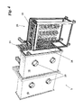
- the device 3 then comprises at least one deposition chamber 19, as shown in Fig. 4 , inside which the high-vacuum can be created and comprising suitable attachments 20 either for insertion of accessories such as a vacuum pump for example or the like, or for insertion of the materials forming the particles constituting the thin film 103.
- chambers 19 can be provided for accomplishment of several steps of the high-vacuum deposition process, in particular two chambers 19 placed in succession, or also several devices 3, adapted to enable accomplishment of several high-vacuum deposition processes simultaneously, taking into account the fact that the latter can be slower than the galvanic processes.
- the deposition chambers 19 preferably have the form of a parallelepiped and comprise a door 21 consisting of a face of said parallelepiped that can be opened.
- Door 21 is preferably consists of a side face, as shown in Fig. 4 .
- Door 21 therefore comprises automatic closing and opening means 22 consisting of electric or fluid-operated pistons.
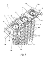
- Frames 10 are inserted into chambers 19 preferably by means of a second trolley 23 ( Figs. 5 and 6 ) that is movable on second rails 24 and extends in a horizontal plane and in a direction preferably perpendicular to the first direction 2a.
- apparatus 1 For the purpose of arranging frames 10 on the second trolleys 23 apparatus 1 comprises an intermediate station 25 adjacent and external to chamber 19, comprising the second trolley 23 disposed on a first portion of the second rails 24.
- the second trolley 23 comprises second mechanical supports 26 similar to the first mechanical supports 18, which conform in shape to the mechanical hooks 15 and are adapted to be connected thereto.
- the second trolley is then rigidly fastened to frames 10 and carries out translation together with the latter on rails 24.
- Said rails are divided into several portions, each at the inside of an individual chamber 19 or intermediate station 25, in such a manner that doors 21 can be closed without interference and trolley 23 can be moved from one portion to another, as shown in Fig. 1 .
- Trolley 23 is suitably moved by appropriate thrust elements (not shown) acting on the movable hooks 16, for example. It can further be connected in a movable manner to a rotation motor, in turn connected to a source of electric energy adapted to rotate shaft 14a, preferably disposed inside the individual chambers 19.
- the objects 100 are disposed on the hooks 11a of the vertical structure 11, placed on frame 10.
- Frame 10 is then placed on the first trolley 8 carrying the frame itself inside the further vats 6a, for cleaning or pickling of the objects 100 and inside the first vat 4a, in the electrolytic bath 4.
- Trolley 8 carries frame 10 and hooks the movable hooks 16 thereof by means of the hooking elements 8c releasing the same at the supporting means 17 placed on vats 4a and 6a.
- an anode is placed, which is connected to a source of electric current too and is made of the same material as the material that is intended to be used for the galvanic film 102.
- the first trolley 8 carries frame 10 onto the intermediate station 25.
- Frame 10 is then rigidly linked to the second trolley 23 ( Fig. 5 ) and is therefore adapted to slide on the second rails 24.
- the first door 21 is then opened and frame 10 linked to the second trolley 23 is conveyed by means of said thrust elements into the first deposition chamber 19.
- the high-vacuum processes such as PVD or CVD processes are applied and the thin film 103 is formed over the galvanic film 102.
- the supporting structures 11 are moved around the movable platforms 12.
- the materials that have to constitute the film, or the precursors of same are made available within the volume of chamber 19 under vacuum, in the form of gases, vapours and/or particles for example.
- the particles or the like present within chamber 19 therefore come into contact with the objects to be coated 100 to which they adhere in a uniform manner if the objects themselves are set in motion, in particular in a rotary, translatory or roto-translatory motion.
- frame 10 linked to the second trolley 23 is conveyed, by means of further thrust elements, into the second deposition chamber 19 with a further opening-closing movement of the second door 21.
- the invention enables important advantages to be achieved.
- device 1 enables coating films 101 made up of galvanic films 102 and thin films 103 as described, to be obtained quickly, practically in a continuous manner, due to the automatic interfacing 25 of the galvanic plant and the vacuum plant that is placed in line too.
- This high-vacuum coating of chromium is suitably obtained with 99% pure chromium, which is a safe product for workers and environment.
- Said process gives aesthetic and surface features even better than chromium plating obtained with hexavalent chromium and does not show the related toxicity drawbacks during working.
- the deposition chambers 19 can have an opening on top, so that the first trolley 8 can transfer the objects 100 also to the inside of the chambers 19 themselves without the intermediate station 25 being required.
- frames 10 comprise supporting structures 11 that are fixed relative to frame 10.
- frame 10 preferably moves inside the deposition chambers 19 and the rotary and/or roto-translatory motion is not necessary.
- the supporting structures in the last-mentioned case, preferably have a square shape, as shown in Fig. 10 .
Applications Claiming Priority (1)
| Application Number | Priority Date | Filing Date | Title |
|---|---|---|---|
| IT000933A ITMI20090933A1 (it) | 2009-05-27 | 2009-05-27 | Apparato per la deposizione di film di rivestimento |
Publications (2)
| Publication Number | Publication Date |
|---|---|
| EP2256233A1 true EP2256233A1 (de) | 2010-12-01 |
| EP2256233B1 EP2256233B1 (de) | 2013-01-23 |
Family
ID=41832484
Family Applications (1)
| Application Number | Title | Priority Date | Filing Date |
|---|---|---|---|
| EP10004780A Not-in-force EP2256233B1 (de) | 2009-05-27 | 2010-05-06 | Vorrichtung zur Abscheidung von Überzugsschichten |
Country Status (2)
| Country | Link |
|---|---|
| EP (1) | EP2256233B1 (de) |
| IT (1) | ITMI20090933A1 (de) |
Families Citing this family (1)
| Publication number | Priority date | Publication date | Assignee | Title |
|---|---|---|---|---|
| EP2650135A1 (de) | 2012-04-12 | 2013-10-16 | KBA-NotaSys SA | Intaglio-Druckplattenbeschichtungsvorrichtung |
Citations (2)
| Publication number | Priority date | Publication date | Assignee | Title |
|---|---|---|---|---|
| EP1129232B1 (de) * | 1998-11-11 | 2003-10-01 | Vacumetal B.V. | Vorrichtung zum beschichten von gegenständen mittels pvd |
| US20050279642A1 (en) * | 2004-06-17 | 2005-12-22 | Klaus Brondum | Common rack for electroplating and PVD coating operations |
Family Cites Families (1)
| Publication number | Priority date | Publication date | Assignee | Title |
|---|---|---|---|---|
| GB0407619D0 (en) * | 2004-04-02 | 2004-05-05 | Jing Mei Ind Holdings Ltd | Chromium plating |
-
2009
- 2009-05-27 IT IT000933A patent/ITMI20090933A1/it unknown
-
2010
- 2010-05-06 EP EP10004780A patent/EP2256233B1/de not_active Not-in-force
Patent Citations (2)
| Publication number | Priority date | Publication date | Assignee | Title |
|---|---|---|---|---|
| EP1129232B1 (de) * | 1998-11-11 | 2003-10-01 | Vacumetal B.V. | Vorrichtung zum beschichten von gegenständen mittels pvd |
| US20050279642A1 (en) * | 2004-06-17 | 2005-12-22 | Klaus Brondum | Common rack for electroplating and PVD coating operations |
Also Published As
| Publication number | Publication date |
|---|---|
| ITMI20090933A1 (it) | 2010-11-28 |
| EP2256233B1 (de) | 2013-01-23 |
Similar Documents
| Publication | Publication Date | Title |
|---|---|---|
| US8124184B2 (en) | Aluminum phosphate compounds, compositions, materials and related metal coatings | |
| CN108884545B (zh) | 热浸镀锌系统和热浸镀锌方法 | |
| JP2013501139A (ja) | コーティングされた基材を調製するためのプロセス、コーティングされた基材、及びその使用 | |
| CN110090754A (zh) | 一种砂芯模生产表面涂料涂覆装置 | |
| AU2003304644B2 (en) | Aluminum phosphate compounds, compositions, materials and related metal coatings | |
| TW200734069A (en) | Dense protective coatings, methods for their preparation and coated articles | |
| CN103590082B (zh) | 一种无磷、无六价铬环保型塑胶电镀方法 | |
| US20160348261A1 (en) | Component oxidized by plasma electrolysis and method for the production thereof | |
| EP2256233B1 (de) | Vorrichtung zur Abscheidung von Überzugsschichten | |
| CN108855771A (zh) | 一种达克罗处理用浸涂烘干一体机 | |
| DE2537256B2 (de) | Vorrichtung zum galvanischen Abscheiden von Aluminium | |
| CN111633304A (zh) | 一种用于镍钛合金电弧熔丝增材制造的气氛保护设备 | |
| CN109046868A (zh) | 一种达克罗处理用浸涂设备 | |
| DE2716805C3 (de) | Vorrichtung zum galvanischen Abscheiden von Aluminium | |
| WO2016003089A1 (ko) | Cvd공정을 통해 알루미늄 등축정 조직을 형성하는 금속 내외장재의 표면처리 방법 및 이를 이용하여 표면처리된 금속 내외장재 | |
| CN115369345B (zh) | 一种铁件热镀锌生产线及其工作方法 | |
| CN101988187B (zh) | 一种真空磁控溅射彩镀设备 | |
| DE2166843A1 (de) | Druckstrahler | |
| CN102226267B (zh) | 在真空室内连续完成喷底漆、烘干、电镀的装置 | |
| CN201442976U (zh) | 一种带有补偿斜靶的真空磁控溅射镀膜机 | |
| CN213802520U (zh) | 一种全自动热浸镀锌前处理结构 | |
| CN102601347A (zh) | 一种模内喷涂法包覆型镁合金铸件铸造装置及其铸造方法 | |
| CN106929803B (zh) | 塑料镀膜生产设备及其生产方法 | |
| CN207452240U (zh) | 新能源汽车逆变器散热片pvd镀膜设备 | |
| EP0257319B1 (de) | Verfahren zum Herstellen von Schutzschichten |
Legal Events
| Date | Code | Title | Description |
|---|---|---|---|
| PUAI | Public reference made under article 153(3) epc to a published international application that has entered the european phase |
Free format text: ORIGINAL CODE: 0009012 |
|
| AK | Designated contracting states |
Kind code of ref document: A1 Designated state(s): AL AT BE BG CH CY CZ DE DK EE ES FI FR GB GR HR HU IE IS IT LI LT LU LV MC MK MT NL NO PL PT RO SE SI SK SM TR |
|
| AX | Request for extension of the european patent |
Extension state: BA ME RS |
|
| 17P | Request for examination filed |
Effective date: 20110518 |
|
| 17Q | First examination report despatched |
Effective date: 20120125 |
|
| RIC1 | Information provided on ipc code assigned before grant |
Ipc: C25D 19/00 20060101ALI20120509BHEP Ipc: C23C 16/54 20060101AFI20120509BHEP Ipc: C25D 17/08 20060101ALI20120509BHEP Ipc: C23C 14/56 20060101ALI20120509BHEP |
|
| REG | Reference to a national code |
Ref country code: DE Ref legal event code: R079 Ref document number: 602010004749 Country of ref document: DE Free format text: PREVIOUS MAIN CLASS: C25D0017080000 Ipc: C25D0017000000 |
|
| GRAP | Despatch of communication of intention to grant a patent |
Free format text: ORIGINAL CODE: EPIDOSNIGR1 |
|
| RIC1 | Information provided on ipc code assigned before grant |
Ipc: C23C 14/56 20060101ALI20120731BHEP Ipc: C25D 17/08 20060101ALI20120731BHEP Ipc: C25D 17/00 20060101AFI20120731BHEP Ipc: C23C 16/54 20060101ALI20120731BHEP Ipc: C25D 19/00 20060101ALI20120731BHEP |
|
| GRAS | Grant fee paid |
Free format text: ORIGINAL CODE: EPIDOSNIGR3 |
|
| GRAA | (expected) grant |
Free format text: ORIGINAL CODE: 0009210 |
|
| AK | Designated contracting states |
Kind code of ref document: B1 Designated state(s): AL AT BE BG CH CY CZ DE DK EE ES FI FR GB GR HR HU IE IS IT LI LT LU LV MC MK MT NL NO PL PT RO SE SI SK SM TR |
|
| REG | Reference to a national code |
Ref country code: GB Ref legal event code: FG4D |
|
| REG | Reference to a national code |
Ref country code: CH Ref legal event code: EP |
|
| REG | Reference to a national code |
Ref country code: AT Ref legal event code: REF Ref document number: 595037 Country of ref document: AT Kind code of ref document: T Effective date: 20130215 Ref country code: CH Ref legal event code: EP |
|
| REG | Reference to a national code |
Ref country code: IE Ref legal event code: FG4D |
|
| REG | Reference to a national code |
Ref country code: CH Ref legal event code: NV Representative=s name: BOVARD AG, CH |
|
| REG | Reference to a national code |
Ref country code: DE Ref legal event code: R096 Ref document number: 602010004749 Country of ref document: DE Effective date: 20130321 |
|
| REG | Reference to a national code |
Ref country code: AT Ref legal event code: MK05 Ref document number: 595037 Country of ref document: AT Kind code of ref document: T Effective date: 20130123 |
|
| REG | Reference to a national code |
Ref country code: LT Ref legal event code: MG4D |
|
| REG | Reference to a national code |
Ref country code: NL Ref legal event code: VDEP Effective date: 20130123 |
|
| PG25 | Lapsed in a contracting state [announced via postgrant information from national office to epo] |
Ref country code: SE Free format text: LAPSE BECAUSE OF FAILURE TO SUBMIT A TRANSLATION OF THE DESCRIPTION OR TO PAY THE FEE WITHIN THE PRESCRIBED TIME-LIMIT Effective date: 20130123 Ref country code: BE Free format text: LAPSE BECAUSE OF FAILURE TO SUBMIT A TRANSLATION OF THE DESCRIPTION OR TO PAY THE FEE WITHIN THE PRESCRIBED TIME-LIMIT Effective date: 20130123 Ref country code: AT Free format text: LAPSE BECAUSE OF FAILURE TO SUBMIT A TRANSLATION OF THE DESCRIPTION OR TO PAY THE FEE WITHIN THE PRESCRIBED TIME-LIMIT Effective date: 20130123 Ref country code: ES Free format text: LAPSE BECAUSE OF FAILURE TO SUBMIT A TRANSLATION OF THE DESCRIPTION OR TO PAY THE FEE WITHIN THE PRESCRIBED TIME-LIMIT Effective date: 20130504 Ref country code: LT Free format text: LAPSE BECAUSE OF FAILURE TO SUBMIT A TRANSLATION OF THE DESCRIPTION OR TO PAY THE FEE WITHIN THE PRESCRIBED TIME-LIMIT Effective date: 20130123 Ref country code: NO Free format text: LAPSE BECAUSE OF FAILURE TO SUBMIT A TRANSLATION OF THE DESCRIPTION OR TO PAY THE FEE WITHIN THE PRESCRIBED TIME-LIMIT Effective date: 20130423 Ref country code: IS Free format text: LAPSE BECAUSE OF FAILURE TO SUBMIT A TRANSLATION OF THE DESCRIPTION OR TO PAY THE FEE WITHIN THE PRESCRIBED TIME-LIMIT Effective date: 20130523 Ref country code: BG Free format text: LAPSE BECAUSE OF FAILURE TO SUBMIT A TRANSLATION OF THE DESCRIPTION OR TO PAY THE FEE WITHIN THE PRESCRIBED TIME-LIMIT Effective date: 20130423 |
|
| PG25 | Lapsed in a contracting state [announced via postgrant information from national office to epo] |
Ref country code: GR Free format text: LAPSE BECAUSE OF FAILURE TO SUBMIT A TRANSLATION OF THE DESCRIPTION OR TO PAY THE FEE WITHIN THE PRESCRIBED TIME-LIMIT Effective date: 20130424 Ref country code: FI Free format text: LAPSE BECAUSE OF FAILURE TO SUBMIT A TRANSLATION OF THE DESCRIPTION OR TO PAY THE FEE WITHIN THE PRESCRIBED TIME-LIMIT Effective date: 20130123 Ref country code: SI Free format text: LAPSE BECAUSE OF FAILURE TO SUBMIT A TRANSLATION OF THE DESCRIPTION OR TO PAY THE FEE WITHIN THE PRESCRIBED TIME-LIMIT Effective date: 20130123 Ref country code: PT Free format text: LAPSE BECAUSE OF FAILURE TO SUBMIT A TRANSLATION OF THE DESCRIPTION OR TO PAY THE FEE WITHIN THE PRESCRIBED TIME-LIMIT Effective date: 20130523 Ref country code: NL Free format text: LAPSE BECAUSE OF FAILURE TO SUBMIT A TRANSLATION OF THE DESCRIPTION OR TO PAY THE FEE WITHIN THE PRESCRIBED TIME-LIMIT Effective date: 20130123 Ref country code: LV Free format text: LAPSE BECAUSE OF FAILURE TO SUBMIT A TRANSLATION OF THE DESCRIPTION OR TO PAY THE FEE WITHIN THE PRESCRIBED TIME-LIMIT Effective date: 20130123 Ref country code: PL Free format text: LAPSE BECAUSE OF FAILURE TO SUBMIT A TRANSLATION OF THE DESCRIPTION OR TO PAY THE FEE WITHIN THE PRESCRIBED TIME-LIMIT Effective date: 20130123 |
|
| PG25 | Lapsed in a contracting state [announced via postgrant information from national office to epo] |
Ref country code: HR Free format text: LAPSE BECAUSE OF FAILURE TO SUBMIT A TRANSLATION OF THE DESCRIPTION OR TO PAY THE FEE WITHIN THE PRESCRIBED TIME-LIMIT Effective date: 20130123 |
|
| PG25 | Lapsed in a contracting state [announced via postgrant information from national office to epo] |
Ref country code: CZ Free format text: LAPSE BECAUSE OF FAILURE TO SUBMIT A TRANSLATION OF THE DESCRIPTION OR TO PAY THE FEE WITHIN THE PRESCRIBED TIME-LIMIT Effective date: 20130123 Ref country code: RO Free format text: LAPSE BECAUSE OF FAILURE TO SUBMIT A TRANSLATION OF THE DESCRIPTION OR TO PAY THE FEE WITHIN THE PRESCRIBED TIME-LIMIT Effective date: 20130123 Ref country code: DK Free format text: LAPSE BECAUSE OF FAILURE TO SUBMIT A TRANSLATION OF THE DESCRIPTION OR TO PAY THE FEE WITHIN THE PRESCRIBED TIME-LIMIT Effective date: 20130123 Ref country code: SK Free format text: LAPSE BECAUSE OF FAILURE TO SUBMIT A TRANSLATION OF THE DESCRIPTION OR TO PAY THE FEE WITHIN THE PRESCRIBED TIME-LIMIT Effective date: 20130123 Ref country code: EE Free format text: LAPSE BECAUSE OF FAILURE TO SUBMIT A TRANSLATION OF THE DESCRIPTION OR TO PAY THE FEE WITHIN THE PRESCRIBED TIME-LIMIT Effective date: 20130123 |
|
| PG25 | Lapsed in a contracting state [announced via postgrant information from national office to epo] |
Ref country code: CY Free format text: LAPSE BECAUSE OF FAILURE TO SUBMIT A TRANSLATION OF THE DESCRIPTION OR TO PAY THE FEE WITHIN THE PRESCRIBED TIME-LIMIT Effective date: 20130123 |
|
| PLBE | No opposition filed within time limit |
Free format text: ORIGINAL CODE: 0009261 |
|
| STAA | Information on the status of an ep patent application or granted ep patent |
Free format text: STATUS: NO OPPOSITION FILED WITHIN TIME LIMIT |
|
| PG25 | Lapsed in a contracting state [announced via postgrant information from national office to epo] |
Ref country code: MC Free format text: LAPSE BECAUSE OF FAILURE TO SUBMIT A TRANSLATION OF THE DESCRIPTION OR TO PAY THE FEE WITHIN THE PRESCRIBED TIME-LIMIT Effective date: 20130123 |
|
| 26N | No opposition filed |
Effective date: 20131024 |
|
| REG | Reference to a national code |
Ref country code: DE Ref legal event code: R097 Ref document number: 602010004749 Country of ref document: DE Effective date: 20131024 |
|
| REG | Reference to a national code |
Ref country code: IE Ref legal event code: MM4A |
|
| PG25 | Lapsed in a contracting state [announced via postgrant information from national office to epo] |
Ref country code: IE Free format text: LAPSE BECAUSE OF NON-PAYMENT OF DUE FEES Effective date: 20130506 |
|
| PG25 | Lapsed in a contracting state [announced via postgrant information from national office to epo] |
Ref country code: MT Free format text: LAPSE BECAUSE OF FAILURE TO SUBMIT A TRANSLATION OF THE DESCRIPTION OR TO PAY THE FEE WITHIN THE PRESCRIBED TIME-LIMIT Effective date: 20130123 |
|
| REG | Reference to a national code |
Ref country code: FR Ref legal event code: PLFP Year of fee payment: 6 |
|
| PG25 | Lapsed in a contracting state [announced via postgrant information from national office to epo] |
Ref country code: SM Free format text: LAPSE BECAUSE OF FAILURE TO SUBMIT A TRANSLATION OF THE DESCRIPTION OR TO PAY THE FEE WITHIN THE PRESCRIBED TIME-LIMIT Effective date: 20130123 |
|
| PG25 | Lapsed in a contracting state [announced via postgrant information from national office to epo] |
Ref country code: TR Free format text: LAPSE BECAUSE OF FAILURE TO SUBMIT A TRANSLATION OF THE DESCRIPTION OR TO PAY THE FEE WITHIN THE PRESCRIBED TIME-LIMIT Effective date: 20130123 |
|
| PG25 | Lapsed in a contracting state [announced via postgrant information from national office to epo] |
Ref country code: LU Free format text: LAPSE BECAUSE OF NON-PAYMENT OF DUE FEES Effective date: 20130506 Ref country code: MK Free format text: LAPSE BECAUSE OF FAILURE TO SUBMIT A TRANSLATION OF THE DESCRIPTION OR TO PAY THE FEE WITHIN THE PRESCRIBED TIME-LIMIT Effective date: 20130123 Ref country code: HU Free format text: LAPSE BECAUSE OF FAILURE TO SUBMIT A TRANSLATION OF THE DESCRIPTION OR TO PAY THE FEE WITHIN THE PRESCRIBED TIME-LIMIT; INVALID AB INITIO Effective date: 20100506 |
|
| PGFP | Annual fee paid to national office [announced via postgrant information from national office to epo] |
Ref country code: CH Payment date: 20150612 Year of fee payment: 6 Ref country code: DE Payment date: 20150602 Year of fee payment: 6 Ref country code: GB Payment date: 20150527 Year of fee payment: 6 |
|
| PGFP | Annual fee paid to national office [announced via postgrant information from national office to epo] |
Ref country code: IT Payment date: 20150522 Year of fee payment: 6 Ref country code: FR Payment date: 20150527 Year of fee payment: 6 |
|
| REG | Reference to a national code |
Ref country code: DE Ref legal event code: R119 Ref document number: 602010004749 Country of ref document: DE |
|
| REG | Reference to a national code |
Ref country code: CH Ref legal event code: PL |
|
| GBPC | Gb: european patent ceased through non-payment of renewal fee |
Effective date: 20160506 |
|
| PG25 | Lapsed in a contracting state [announced via postgrant information from national office to epo] |
Ref country code: CH Free format text: LAPSE BECAUSE OF NON-PAYMENT OF DUE FEES Effective date: 20160531 Ref country code: LI Free format text: LAPSE BECAUSE OF NON-PAYMENT OF DUE FEES Effective date: 20160531 |
|
| PG25 | Lapsed in a contracting state [announced via postgrant information from national office to epo] |
Ref country code: IT Free format text: LAPSE BECAUSE OF NON-PAYMENT OF DUE FEES Effective date: 20160506 |
|
| REG | Reference to a national code |
Ref country code: FR Ref legal event code: ST Effective date: 20170131 |
|
| PG25 | Lapsed in a contracting state [announced via postgrant information from national office to epo] |
Ref country code: FR Free format text: LAPSE BECAUSE OF NON-PAYMENT OF DUE FEES Effective date: 20160531 Ref country code: DE Free format text: LAPSE BECAUSE OF NON-PAYMENT OF DUE FEES Effective date: 20161201 |
|
| PG25 | Lapsed in a contracting state [announced via postgrant information from national office to epo] |
Ref country code: GB Free format text: LAPSE BECAUSE OF NON-PAYMENT OF DUE FEES Effective date: 20160506 |
|
| PG25 | Lapsed in a contracting state [announced via postgrant information from national office to epo] |
Ref country code: AL Free format text: LAPSE BECAUSE OF FAILURE TO SUBMIT A TRANSLATION OF THE DESCRIPTION OR TO PAY THE FEE WITHIN THE PRESCRIBED TIME-LIMIT Effective date: 20130123 |
|
| P01 | Opt-out of the competence of the unified patent court (upc) registered |
Effective date: 20230607 |