EP2251547A2 - Vacuum pump - Google Patents
Vacuum pump Download PDFInfo
- Publication number
- EP2251547A2 EP2251547A2 EP10004024A EP10004024A EP2251547A2 EP 2251547 A2 EP2251547 A2 EP 2251547A2 EP 10004024 A EP10004024 A EP 10004024A EP 10004024 A EP10004024 A EP 10004024A EP 2251547 A2 EP2251547 A2 EP 2251547A2
- Authority
- EP
- European Patent Office
- Prior art keywords
- blade
- impeller
- vacuum pump
- blades
- partial
- Prior art date
- Legal status (The legal status is an assumption and is not a legal conclusion. Google has not performed a legal analysis and makes no representation as to the accuracy of the status listed.)
- Granted
Links
- 238000005086 pumping Methods 0.000 claims description 26
- 238000005192 partition Methods 0.000 abstract 1
- 238000013461 design Methods 0.000 description 6
- 230000008901 benefit Effects 0.000 description 3
- 238000011161 development Methods 0.000 description 3
- 230000018109 developmental process Effects 0.000 description 3
- 230000006872 improvement Effects 0.000 description 3
- 238000004519 manufacturing process Methods 0.000 description 3
- 238000012546 transfer Methods 0.000 description 3
- 238000000034 method Methods 0.000 description 2
- 230000009471 action Effects 0.000 description 1
- 230000007246 mechanism Effects 0.000 description 1
- 230000008569 process Effects 0.000 description 1
- 230000000630 rising effect Effects 0.000 description 1
- 238000012549 training Methods 0.000 description 1
Images

Classifications
-
- F—MECHANICAL ENGINEERING; LIGHTING; HEATING; WEAPONS; BLASTING
- F04—POSITIVE - DISPLACEMENT MACHINES FOR LIQUIDS; PUMPS FOR LIQUIDS OR ELASTIC FLUIDS
- F04D—NON-POSITIVE-DISPLACEMENT PUMPS
- F04D19/00—Axial-flow pumps
- F04D19/02—Multi-stage pumps
- F04D19/04—Multi-stage pumps specially adapted to the production of a high vacuum, e.g. molecular pumps
- F04D19/044—Holweck-type pumps
-
- F—MECHANICAL ENGINEERING; LIGHTING; HEATING; WEAPONS; BLASTING
- F04—POSITIVE - DISPLACEMENT MACHINES FOR LIQUIDS; PUMPS FOR LIQUIDS OR ELASTIC FLUIDS
- F04D—NON-POSITIVE-DISPLACEMENT PUMPS
- F04D17/00—Radial-flow pumps, e.g. centrifugal pumps; Helico-centrifugal pumps
- F04D17/08—Centrifugal pumps
- F04D17/16—Centrifugal pumps for displacing without appreciable compression
- F04D17/168—Pumps specially adapted to produce a vacuum
-
- F—MECHANICAL ENGINEERING; LIGHTING; HEATING; WEAPONS; BLASTING
- F04—POSITIVE - DISPLACEMENT MACHINES FOR LIQUIDS; PUMPS FOR LIQUIDS OR ELASTIC FLUIDS
- F04D—NON-POSITIVE-DISPLACEMENT PUMPS
- F04D19/00—Axial-flow pumps
- F04D19/02—Multi-stage pumps
- F04D19/04—Multi-stage pumps specially adapted to the production of a high vacuum, e.g. molecular pumps
- F04D19/046—Combinations of two or more different types of pumps
-
- F—MECHANICAL ENGINEERING; LIGHTING; HEATING; WEAPONS; BLASTING
- F04—POSITIVE - DISPLACEMENT MACHINES FOR LIQUIDS; PUMPS FOR LIQUIDS OR ELASTIC FLUIDS
- F04D—NON-POSITIVE-DISPLACEMENT PUMPS
- F04D23/00—Other rotary non-positive-displacement pumps
- F04D23/008—Regenerative pumps
-
- F—MECHANICAL ENGINEERING; LIGHTING; HEATING; WEAPONS; BLASTING
- F04—POSITIVE - DISPLACEMENT MACHINES FOR LIQUIDS; PUMPS FOR LIQUIDS OR ELASTIC FLUIDS
- F04D—NON-POSITIVE-DISPLACEMENT PUMPS
- F04D29/00—Details, component parts, or accessories
- F04D29/26—Rotors specially for elastic fluids
- F04D29/28—Rotors specially for elastic fluids for centrifugal or helico-centrifugal pumps for radial-flow or helico-centrifugal pumps
-
- F—MECHANICAL ENGINEERING; LIGHTING; HEATING; WEAPONS; BLASTING
- F04—POSITIVE - DISPLACEMENT MACHINES FOR LIQUIDS; PUMPS FOR LIQUIDS OR ELASTIC FLUIDS
- F04D—NON-POSITIVE-DISPLACEMENT PUMPS
- F04D29/00—Details, component parts, or accessories
- F04D29/40—Casings; Connections of working fluid
- F04D29/52—Casings; Connections of working fluid for axial pumps
- F04D29/522—Casings; Connections of working fluid for axial pumps especially adapted for elastic fluid pumps
Definitions
- the invention relates to a vacuum pump according to the preamble of the first claim.
- Vacuum pumps with side channel pumping stages are known in the art and are gaining increasing economic importance. When used in a turbomolecular pump, a side channel pumping stage allows the turbomolecular pump to be ejected against higher pressures. Vacuum pumps with Holweck and side channel pumping stage achieve ultimate pressures in the molecular flow range in very compact sizes.
- An example of such a vacuum pump is the DE 19930952 A1 which is equipped in the intake with a parallel working Holweckpump note and in the gas stream subsequently with a plurality of side channel pumping stages.
- the impellers used in these bykanalpumpgen are simple: the blades of the disc-shaped impeller are arranged at the edge and are in the radial direction of the disc from. Between the blades a center bar runs around, which has the full blade height along the entire impeller circumference.
- the vacuum characteristics of the side channel pumping stage in particular the suction capacity and the pressure ratio between inlet and outlet, depend on the design of the blades, the channel and the gap between rotating and stationary parts. As a rule, good vacuum characteristics lead to rising production costs.
- the geometry of the blade according to claim 1 is inexpensive to produce. Compared to the prior art mentioned above, an angle between at least one partial blade and the direction of movement of the blade of less than 90 ° results in an improvement in the pressure ratio between inlet and outlet of the side channel pumping stage in the region of the rough vacuum.
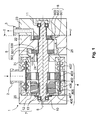
- the vacuum pump 1 of the embodiment is shown in FIG Fig. 1 , shown in longitudinal section.
- the housing of the vacuum pump provided with a gas inlet 2 and a gas outlet 3 has a plurality of housing parts 20, 21, 22 and 23, in which the components described below are accommodated.
- the gas first passes into the molecular pump stage 4, which is designed here according to Holweck design.
- This comprises an inner stator 405 with an inner thread groove 407 and an outer stator 406 with an outer thread groove 408.
- the thread grooves run helically and cooperate with a rotating cylinder 402 located between inner stator and outer stator in such a way that a pumping action occurs in the molecular flow region.
- the cylinder is mounted on a carrier 400, which in turn is connected to the shaft 8.
- the molecular pumping stage is symmetrical and has a second cylinder 402 'which cooperates with associated stator components. This design results in a parallel conveying mechanism.
- the shaft is rotated by a drive 7 in rotation.
- This drive comprises an electric coil 12 on the stator side and a permanent magnet 13 on the shaft side.
- the shaft is mounted in roller bearings 10 and 11.
- the gas From the molecular pump stage, the gas enters downstream through the first transfer channel 24 into a high-vacuum-side side channel stage 5.
- This has a rotor 500, which is provided with at least one rotor blade. This runs in the side channel 501.
- the gas further compressed in this pumping stage is transferred via the second transfer channel 25 to the side channel pumping stage 6, where it is further compressed and finally discharged via the gas outlet from the vacuum pump.
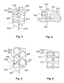
- Fig. 2 the side channel pumping stage 6 is shown in a section along the line II '.
- the housing part 22, which houses the side channel pumping stage, has an annular side channel 601.
- the ring of this side channel is interrupted by a breaker 604. This separates the intake and discharge side of each other and triggers the guided on the impeller gas flow from this.
- in the Side channel runs around the at least one blade 602, which is arranged at the edge 603 of the impeller 600. It extends at this edge in the radial direction.
- the impeller is rotated by the shaft 8 and gas enters the side channel through the transfer channel 25, it is moved with the blade along the channel.
- This entrainment of the gas in the circumferential direction ends at the Abtreifer 604. At this the gas is transferred to the subsequent channel. This then leads to a further pumping stage or to the gas outlet 3.
- the design of the blade of the impeller is in Fig. 3 shown in a view of the edge.
- the blade 602 has a first partial blade 621 and a second partial blade 622.
- Each of these vanes has a partial bucket back 625 and 626.
- At least one of these two vanes forms an angle 615 of less than 90 ° with the direction of travel 607 of the bucket. It is advantageous if both partial blades are inclined at such an angle and together form an open V in the direction of movement. This measure increases the pressure ratio, which can be achieved with the blade.
- a further increase is achieved by the chamfer 616, which are provided on the partial blade rear sides 625 and 626 and on which lie in the plane of the impeller outer edge of the sub-blades.
- a saw blade saws the edge of the impeller and is inclined against the axis of rotation of the impeller, ie the axis of rotation is not in the plane of the saw blade.
- the impeller has in addition to the blade 602 still another blade 612, which is advantageously designed similar. Between the blades 602 and 612, a central web 630 is arranged.
- the design of the Mittelsteges is based Fig. 4 clarified. This shows a section along the line II-II '.
- the central web 630 is disposed between the blades 602 and 612. Its height 631 is at least partially smaller than the blade height 632, so that a continuous space between the blades is formed. This leads to an improved pressure ratio.
- the geometry is in turn easily produced by sawing. During sawing, the saw blade plunges over the center of the edge of the impeller and removes the material of the center bar. If the saw blade is inclined as described above, a sawing process results in a geometry in which the higher part of the central web is arranged in front of the blade 602 in relation to the direction of movement 607.
- a further development of the shovel shows the top view of the edge of the impeller in Fig. 5 ,
- the blade 602 has two partial blades 651 and 652.
- Each of the sub-blades has a partial bucket rear 653 and 654.
- a chamfer 656 is arranged, which lies on the lying in the plane of the impeller outer edge of the sub-blade.
- the sub-blades form an angle 615 'of less than 90 ° with the direction of movement 607.
- the sub-blades are offset by an offset 661 in the direction of movement against each other.
- the partial vane backs extend beyond the center 660 of the impeller.
- FIG. 6 is a view of the edge of the rotor of the high-vacuum side side channel pumping stage 5 shown.
- the blade 502 arranged at the edge of the rotor has partial blades 551 and 552 with a partial rear side 513.
- a chamfer is provided at the back part of the bucket.
- FIGS. 3 to 6 shown structures are repeated several times and occur along the circumference of the impeller in an integer multiple.
- the combination of a molecular pumping stage 4 with a high-vacuum side-channel pumping stage, which after a Fig. 6 designed rotor having, and with a side channel pumping stage, the impeller having the features of the FIGS. 3 to 5 has, results in a cost-effectively manufacturable, compact vacuum pump with improved vacuum characteristics.
Abstract
Description
Die Erfindung betrifft eine Vakuumpumpe nach dem Oberbegriff des ersten Anspruchs.The invention relates to a vacuum pump according to the preamble of the first claim.
Vakuumpumpen mit Seitenkanalpumpstufen sind im Stand der Technik bekannt und erlangen zunehmend wirtschaftliche Bedeutung. Beim Einsatz in einer Turbomolekularpumpe ermöglicht eine Seitenkanalpumpstufe, die Turbomolekularpumpe gegen höhere Drucke ausstoßen zu lassen. Vakuumpumpen mit Holweck- und Seitenkanalpumpstufe erreichen bei sehr kompakten Baugrößen Enddrücke im molekularen Strömungsbereich. Ein Beispiel für eine solche Vakuumpumpe gibt die
Die Vakuumkennwerte der Seitenkanalpumpstufe, insbesondere Saugvermögen und Druckverhältnis zwischen Einlass und Auslass, hängen von der Gestaltung der Schaufeln, des Kanals und der Spalte zwischen rotierenden und stehenden Teile ab. In der Regel führen gute Vakuumkennwerte zu steigenden Herstellkosten.The vacuum characteristics of the side channel pumping stage, in particular the suction capacity and the pressure ratio between inlet and outlet, depend on the design of the blades, the channel and the gap between rotating and stationary parts. As a rule, good vacuum characteristics lead to rising production costs.
Andererseits besteht die Notwendigkeit, die Kosten für die Herstellung der pumpaktiven Teile der Seitenkanalpumpe gering zu halten.On the other hand, there is a need to keep the cost of producing the pump-active parts of the side channel pump low.
Das oben beschriebene Laufrad stellt bisher einen guten Kompromiss dar, für den jedoch eine Verbesserung gesucht wird.The impeller described above represents a good compromise, but for which an improvement is sought.
Es ist daher Aufgabe, eine Vakuumpumpe zu schaffen, deren Seitenkanalpumpstufe verbesserte Vakuumkennwerte und gleichzeitig eine einfach herzustellende Geometrie der pumpaktiven Bauteile besitzt.It is therefore an object to provide a vacuum pump whose Seitenkanalpumpstufe has improved vacuum characteristics and at the same time easy to manufacture geometry of the pump-active components.
Die Aufgabe wird gelöst durch die Merkmale des unabhängigen Anspruchs 1. Vorteilhafte Ausgestaltungen der Erfindung sind in den Unteransprüchen 2 bis 6 gekennzeichnet.The object is solved by the features of
Die Geometrie der Schaufel nach Anspruch 1 ist kostengünstig herstellbar. Im Vergleich zum eingangs genannten Stand der Technik ergibt sich durch einen Winkel zwischen wenigstens einer Teilschaufel und der Bewegungsrichtung der Schaufel von weniger als 90° eine Verbesserung des Druckverhältnisses zwischen Einlass und Auslass der Seitenkanalpumpstufe im Bereich des Grobvakuums.The geometry of the blade according to
Dieser Vorteil wird vertieft, wenn zusätzlich ein Mittelsteg zwischen benachbarten Schaufeln wenigstens abschnittsweise eine geringere Höhe als die Schaufel aufweist.This advantage is enhanced if, in addition, a central web between adjacent blades at least in sections has a lower height than the blade.
Eine zusätzliche Verbesserung der Vakuumkennwerte, insbesondere des Druckverhältnisses, wird erzielt, wenn wenigstens eine Teilschaufel eine in Bezug zur Drehrichtung nacheilende Rückseite aufweist, die sich über die Mitte des Randes des Laufrades erstreckt.An additional improvement of the vacuum characteristics, in particular the pressure ratio, is achieved if at least one partial vane has a rearward-trailing back which extends over the center of the rim of the impeller.
Eine zusätzliche Ausweitung des Vorteils wird erreicht, wenn an der Rückseite der Schaufel eine Fase angebracht ist.An additional extension of the advantage is achieved if a bevel is attached to the back of the blade.
Vorteilhaft und das Ergebnis weiter verbessernd wirkt ein Versatz der Teilschaufeln in Umfangsrichtung.Advantageous and further improving the result is an offset of the partial blades in the circumferential direction.
Eine vorteilhafte Kombination ergibt sich, wenn die Seitenkanalpumpstufe im Gasstrom hinter einer weiteren Seitenkanalpumpstufe angeordnet ist, welche einen Rotor mit einer Rotorschaufel beinhaltet, welche an einer in Bezug zur Drehrichtung zurückliegenden Seite eine Fase aufweist. Diese Wahl der Schaufelgestaltungen erlaubt eine verringerte Zahl an Seitenkanalpumpstufen im Vergleich zum Stand der Technik und reduziert daher die Herstellkosten bei verbesserten Vakuumkennwerten.An advantageous combination results when the side channel pumping stage is arranged in the gas flow behind another side channel pumping stage, which includes a rotor with a rotor blade, which has a chamfer on a side lying in relation to the direction of rotation. This choice of bucket designs allows for a reduced number of side channel pumping stages compared to the prior art and therefore reduces manufacturing costs with improved vacuum ratings.
An Hand eines Ausführungsbeispiels seiner Weiterbildungen soll die Erfindung näher erläutert und die Darstellung ihrer Vorteile vertieft werden.
Es zeigen:
- Fig. 1:
- Schnitt in Wellenrichtung durch eine Vakuumpumpe mit einer Seitenkanalpumpstufe.
- Fig. 2:
- Schnitt quer zur Wellenachse durch die Seitenkanalpumpstufe entlang I-I'.
- Fig. 3:
- Blick auf ein Laufrad mit erster und zweiter Schaufel.
- Fig. 4:
- Schnitt durch das Laufrad mit erster und zweiter Schaufel entlang der Linie II-II'.
- Fig. 5:
- Sicht auf einen Abschnitt mit einigen Schaufeln in einer Weiterbildung.
- Fig. 6:
- Sicht auf einen Abschnitt des Rotors einer weiteren Pumpstufe.
Show it:
- Fig. 1:
- Cut in the shaft direction by a vacuum pump with a side channel pumping stage.
- Fig. 2:
- Section transverse to the shaft axis through the side channel pumping stage along I-I '.
- 3:
- View of an impeller with first and second blades.
- 4:
- Section through the impeller with first and second blades along the line II-II '.
- Fig. 5:
- View of a section with some blades in a training.
- Fig. 6:
- View of a section of the rotor of another pumping stage.
Die Vakuumpumpe 1 des Ausführungsbeispiels ist in
Durch den Gaseinlass gelangt das Gas zunächst in die molekulare Pumpstufe 4, die hier nach Holweck-Bauart gestaltet ist. Diese umfasst einen Innenstator 405 mit einer inneren Gewindenut 407 und einen Außenstator 406 mit einer äußeren Gewindenut 408. Die Gewindenuten verlaufen schraubengangartig und wirken mit einem zwischen Innenstator und Außenstator befindlichen, rotierenden Zylinder 402 derart zusammen, dass sich im molekularen Strömungsbereich eine Pumpwirkung einstellt. Der Zylinder ist auf einem Träger 400 angebracht, welcher seinerseits mit der Welle 8 verbunden ist. Die molekulare Pumpstufe ist symmetrisch aufgebaut und weist einen zweiten Zylinder 402' auf, der mit ihr zugeordneten Statorbauteilen zusammenwirkt. Durch diese Gestaltung ergibt sich ein paralleler Fördermechanismus.Through the gas inlet, the gas first passes into the
Die Welle wird von einem Antrieb 7 in Drehung versetzt. Dieser Antrieb umfasst statorseitig eine elektrische Spule 12 und wellenseitig einen Permanentmagneten 13. Gelagert ist die Welle in Wälzlagern 10 und 11.The shaft is rotated by a
Aus der molekularen Pumpstufe tritt das Gas stromabwärts durch den ersten Übergabekanal 24 in eine hochvakuumseitige Seitenkanalstufe 5 ein. Diese weist einen Rotor 500 auf, welcher mit wenigstens einer Rotorschaufel versehen ist. Diese läuft in dem Seitenkanal 501 um. Das in dieser Pumpstufe weiter verdichtete Gas wird über den zweiten Übergabekanal 25 an die Seitenkanalpumpstufe 6 übergeben, dort weiterverdichtet und schließlich über den Gasauslass aus der Vakuumpumpe ausgestoßen.From the molecular pump stage, the gas enters downstream through the
In
Die Gestaltung der Schaufel des Laufrades ist in
Das Laufrad weist neben der Schaufel 602 noch eine weitere Schaufel 612 auf, die vorteilhaft gleichartig gestaltet ist. Zwischen den Schaufeln 602 und 612 ist ein Mittelsteg 630 angeordnet.The impeller has in addition to the
Die Gestaltung des Mittelsteges wird anhand
Eine Weiterbildung der Schaufel zeigt der Draufblick auf den Rand des Laufrades in
In
Die in den
Claims (6)
Applications Claiming Priority (1)
| Application Number | Priority Date | Filing Date | Title |
|---|---|---|---|
| DE102009021620.0A DE102009021620B4 (en) | 2009-05-16 | 2009-05-16 | Vacuum pump |
Publications (3)
| Publication Number | Publication Date |
|---|---|
| EP2251547A2 true EP2251547A2 (en) | 2010-11-17 |
| EP2251547A3 EP2251547A3 (en) | 2014-07-09 |
| EP2251547B1 EP2251547B1 (en) | 2016-04-06 |
Family
ID=42154827
Family Applications (1)
| Application Number | Title | Priority Date | Filing Date |
|---|---|---|---|
| EP10004024.5A Not-in-force EP2251547B1 (en) | 2009-05-16 | 2010-04-16 | Vacuum pump |
Country Status (3)
| Country | Link |
|---|---|
| EP (1) | EP2251547B1 (en) |
| JP (1) | JP5680334B2 (en) |
| DE (1) | DE102009021620B4 (en) |
Cited By (3)
| Publication number | Priority date | Publication date | Assignee | Title |
|---|---|---|---|---|
| EP2933497A3 (en) * | 2014-04-17 | 2015-12-02 | Pfeiffer Vacuum GmbH | Vacuum pump |
| EP2565464B1 (en) * | 2011-09-05 | 2019-04-24 | Pfeiffer Vacuum GmbH | Vacuum pump |
| US10337517B2 (en) | 2012-01-27 | 2019-07-02 | Edwards Limited | Gas transfer vacuum pump |
Families Citing this family (4)
| Publication number | Priority date | Publication date | Assignee | Title |
|---|---|---|---|---|
| DE102011118661A1 (en) * | 2011-11-16 | 2013-05-16 | Pfeiffer Vacuum Gmbh | Friction vacuum pump |
| DE102012003680A1 (en) | 2012-02-23 | 2013-08-29 | Pfeiffer Vacuum Gmbh | vacuum pump |
| DE102015113821B4 (en) | 2014-08-27 | 2020-06-04 | Pfeiffer Vacuum Gmbh | Vacuum pump |
| EP3594498B1 (en) | 2019-11-06 | 2022-01-05 | Pfeiffer Vacuum Gmbh | System with a recirculation device |
Citations (1)
| Publication number | Priority date | Publication date | Assignee | Title |
|---|---|---|---|---|
| DE19930952A1 (en) | 1999-07-05 | 2001-01-11 | Pfeiffer Vacuum Gmbh | Vacuum pump |
Family Cites Families (12)
| Publication number | Priority date | Publication date | Assignee | Title |
|---|---|---|---|---|
| DE2405890A1 (en) * | 1974-02-07 | 1975-08-14 | Siemens Ag | SIDE CHANNEL RING COMPRESSOR |
| JPS61210294A (en) * | 1985-03-13 | 1986-09-18 | Nishimura Denki Kk | Blower |
| JP2536571B2 (en) * | 1987-12-25 | 1996-09-18 | ダイキン工業株式会社 | Eddy current type turbo machine |
| JPH0689758B2 (en) * | 1988-06-28 | 1994-11-14 | ダイキン工業株式会社 | Vortex type turbomachine |
| US5358373A (en) * | 1992-04-29 | 1994-10-25 | Varian Associates, Inc. | High performance turbomolecular vacuum pumps |
| US5527149A (en) * | 1994-06-03 | 1996-06-18 | Coltec Industries Inc. | Extended range regenerative pump with modified impeller and/or housing |
| JPH10196586A (en) * | 1997-01-06 | 1998-07-31 | Hitachi Ltd | Turbo vacuum pump |
| DE19955955A1 (en) * | 1999-11-19 | 2001-06-13 | Siemens Ag | Side channel machine e.g. high power fan |
| JP3800128B2 (en) | 2001-07-31 | 2006-07-26 | 株式会社デンソー | Impeller and turbine fuel pump |
| GB0229356D0 (en) | 2002-12-17 | 2003-01-22 | Boc Group Plc | Vacuum pumping arrangement |
| JP4524349B2 (en) | 2003-02-25 | 2010-08-18 | 日立オートモティブシステムズ株式会社 | Turbine type fuel pump |
| DE102005025132A1 (en) | 2005-06-01 | 2006-12-07 | Robert Bosch Gmbh | delivery unit |
-
2009
- 2009-05-16 DE DE102009021620.0A patent/DE102009021620B4/en not_active Expired - Fee Related
-
2010
- 2010-04-16 EP EP10004024.5A patent/EP2251547B1/en not_active Not-in-force
- 2010-05-12 JP JP2010109856A patent/JP5680334B2/en active Active
Patent Citations (1)
| Publication number | Priority date | Publication date | Assignee | Title |
|---|---|---|---|---|
| DE19930952A1 (en) | 1999-07-05 | 2001-01-11 | Pfeiffer Vacuum Gmbh | Vacuum pump |
Cited By (4)
| Publication number | Priority date | Publication date | Assignee | Title |
|---|---|---|---|---|
| EP2565464B1 (en) * | 2011-09-05 | 2019-04-24 | Pfeiffer Vacuum GmbH | Vacuum pump |
| DE102011112689B4 (en) | 2011-09-05 | 2024-03-21 | Pfeiffer Vacuum Gmbh | vacuum pump |
| US10337517B2 (en) | 2012-01-27 | 2019-07-02 | Edwards Limited | Gas transfer vacuum pump |
| EP2933497A3 (en) * | 2014-04-17 | 2015-12-02 | Pfeiffer Vacuum GmbH | Vacuum pump |
Also Published As
| Publication number | Publication date |
|---|---|
| EP2251547B1 (en) | 2016-04-06 |
| EP2251547A3 (en) | 2014-07-09 |
| DE102009021620B4 (en) | 2021-07-29 |
| JP5680334B2 (en) | 2015-03-04 |
| DE102009021620A1 (en) | 2010-11-18 |
| JP2010265894A (en) | 2010-11-25 |
Similar Documents
| Publication | Publication Date | Title |
|---|---|---|
| EP2251547B1 (en) | Vacuum pump | |
| DE3932228C2 (en) | ||
| DE3014425C2 (en) | Side channel pump | |
| DE69734028T2 (en) | vacuum pump | |
| DE3919529C2 (en) | Vacuum pump | |
| EP1948939B1 (en) | Radial compressor rotor | |
| DE10327574B4 (en) | Impeller for a fuel pump | |
| EP2295812B1 (en) | Vacuum pump | |
| DE2534528A1 (en) | VACUUM PUMP | |
| DE1428191A1 (en) | Centrifugal blower | |
| DE2531323A1 (en) | ELECTRIC FAN | |
| DE60035842T2 (en) | vacuum pumps | |
| EP1811184A1 (en) | Impeller of a pump unit and corresponding pump unit | |
| EP2253851B1 (en) | Vacuum pump | |
| EP0363503B1 (en) | Pump stage for a high vacuum pump | |
| DE102005049938B3 (en) | Rotor for fluid flow machine e.g. pump, has wing profile unit including convex elevation on outer mantel surface, axial hollow space enclosed in interior, and opening between space and mantel surface in region of profile units | |
| EP0752066A1 (en) | Device for reducing noise in centrifugal pumps | |
| EP3088743B1 (en) | Side-channel vacuum pump stage with a stripper that is slanted on the suction side | |
| DE3128372A1 (en) | "PERIPHERAL CHANNEL PUMP" | |
| EP2933497A2 (en) | Vacuum pump | |
| DE10008691B4 (en) | Gas friction pump | |
| DE3303460A1 (en) | SELF-PRIMING SIDE CHANNEL PUMP | |
| DE10048695A1 (en) | Side channel pump for conveying fluid gas mixtures has pump channel running in a spiral coil round rotor | |
| DE1728419A1 (en) | Liquid ring compressor | |
| DE102005040305B4 (en) | Side channel machine |
Legal Events
| Date | Code | Title | Description |
|---|---|---|---|
| PUAI | Public reference made under article 153(3) epc to a published international application that has entered the european phase |
Free format text: ORIGINAL CODE: 0009012 |
|
| AK | Designated contracting states |
Kind code of ref document: A2 Designated state(s): AT BE BG CH CY CZ DE DK EE ES FI FR GB GR HR HU IE IS IT LI LT LU LV MC MK MT NL NO PL PT RO SE SI SK SM TR |
|
| AX | Request for extension of the european patent |
Extension state: AL BA ME RS |
|
| PUAL | Search report despatched |
Free format text: ORIGINAL CODE: 0009013 |
|
| RIC1 | Information provided on ipc code assigned before grant |
Ipc: F04D 29/52 20060101ALI20140528BHEP Ipc: F04D 19/04 20060101AFI20140528BHEP Ipc: F04D 29/28 20060101ALI20140528BHEP Ipc: F04D 23/00 20060101ALI20140528BHEP |
|
| AK | Designated contracting states |
Kind code of ref document: A3 Designated state(s): AT BE BG CH CY CZ DE DK EE ES FI FR GB GR HR HU IE IS IT LI LT LU LV MC MK MT NL NO PL PT RO SE SI SK SM TR |
|
| AX | Request for extension of the european patent |
Extension state: AL BA ME RS |
|
| 17P | Request for examination filed |
Effective date: 20141216 |
|
| RBV | Designated contracting states (corrected) |
Designated state(s): AT BE BG CH CY CZ DE DK EE ES FI FR GB GR HR HU IE IS IT LI LT LU LV MC MK MT NL NO PL PT RO SE SI SK SM TR |
|
| 17Q | First examination report despatched |
Effective date: 20150617 |
|
| REG | Reference to a national code |
Ref country code: DE Ref legal event code: R079 Ref document number: 502010011379 Country of ref document: DE Free format text: PREVIOUS MAIN CLASS: F04D0019040000 Ipc: F04D0017160000 |
|
| GRAP | Despatch of communication of intention to grant a patent |
Free format text: ORIGINAL CODE: EPIDOSNIGR1 |
|
| RIC1 | Information provided on ipc code assigned before grant |
Ipc: F04D 29/52 20060101ALI20151021BHEP Ipc: F04D 29/28 20060101ALI20151021BHEP Ipc: F04D 17/16 20060101AFI20151021BHEP Ipc: F04D 23/00 20060101ALI20151021BHEP Ipc: F04D 19/04 20060101ALI20151021BHEP |
|
| INTG | Intention to grant announced |
Effective date: 20151103 |
|
| GRAS | Grant fee paid |
Free format text: ORIGINAL CODE: EPIDOSNIGR3 |
|
| GRAA | (expected) grant |
Free format text: ORIGINAL CODE: 0009210 |
|
| AK | Designated contracting states |
Kind code of ref document: B1 Designated state(s): AT BE BG CH CY CZ DE DK EE ES FI FR GB GR HR HU IE IS IT LI LT LU LV MC MK MT NL NO PL PT RO SE SI SK SM TR |
|
| REG | Reference to a national code |
Ref country code: GB Ref legal event code: FG4D Free format text: NOT ENGLISH |
|
| REG | Reference to a national code |
Ref country code: AT Ref legal event code: REF Ref document number: 788146 Country of ref document: AT Kind code of ref document: T Effective date: 20160415 Ref country code: CH Ref legal event code: EP |
|
| REG | Reference to a national code |
Ref country code: IE Ref legal event code: FG4D Free format text: LANGUAGE OF EP DOCUMENT: GERMAN |
|
| REG | Reference to a national code |
Ref country code: DE Ref legal event code: R096 Ref document number: 502010011379 Country of ref document: DE |
|
| REG | Reference to a national code |
Ref country code: LT Ref legal event code: MG4D Ref country code: NL Ref legal event code: MP Effective date: 20160406 |
|
| PG25 | Lapsed in a contracting state [announced via postgrant information from national office to epo] |
Ref country code: BE Free format text: LAPSE BECAUSE OF NON-PAYMENT OF DUE FEES Effective date: 20160430 |
|
| PG25 | Lapsed in a contracting state [announced via postgrant information from national office to epo] |
Ref country code: NL Free format text: LAPSE BECAUSE OF FAILURE TO SUBMIT A TRANSLATION OF THE DESCRIPTION OR TO PAY THE FEE WITHIN THE PRESCRIBED TIME-LIMIT Effective date: 20160406 |
|
| PG25 | Lapsed in a contracting state [announced via postgrant information from national office to epo] |
Ref country code: FI Free format text: LAPSE BECAUSE OF FAILURE TO SUBMIT A TRANSLATION OF THE DESCRIPTION OR TO PAY THE FEE WITHIN THE PRESCRIBED TIME-LIMIT Effective date: 20160406 Ref country code: NO Free format text: LAPSE BECAUSE OF FAILURE TO SUBMIT A TRANSLATION OF THE DESCRIPTION OR TO PAY THE FEE WITHIN THE PRESCRIBED TIME-LIMIT Effective date: 20160706 Ref country code: PL Free format text: LAPSE BECAUSE OF FAILURE TO SUBMIT A TRANSLATION OF THE DESCRIPTION OR TO PAY THE FEE WITHIN THE PRESCRIBED TIME-LIMIT Effective date: 20160406 Ref country code: IS Free format text: LAPSE BECAUSE OF FAILURE TO SUBMIT A TRANSLATION OF THE DESCRIPTION OR TO PAY THE FEE WITHIN THE PRESCRIBED TIME-LIMIT Effective date: 20160806 Ref country code: LT Free format text: LAPSE BECAUSE OF FAILURE TO SUBMIT A TRANSLATION OF THE DESCRIPTION OR TO PAY THE FEE WITHIN THE PRESCRIBED TIME-LIMIT Effective date: 20160406 |
|
| PG25 | Lapsed in a contracting state [announced via postgrant information from national office to epo] |
Ref country code: SE Free format text: LAPSE BECAUSE OF FAILURE TO SUBMIT A TRANSLATION OF THE DESCRIPTION OR TO PAY THE FEE WITHIN THE PRESCRIBED TIME-LIMIT Effective date: 20160406 Ref country code: HR Free format text: LAPSE BECAUSE OF FAILURE TO SUBMIT A TRANSLATION OF THE DESCRIPTION OR TO PAY THE FEE WITHIN THE PRESCRIBED TIME-LIMIT Effective date: 20160406 Ref country code: GR Free format text: LAPSE BECAUSE OF FAILURE TO SUBMIT A TRANSLATION OF THE DESCRIPTION OR TO PAY THE FEE WITHIN THE PRESCRIBED TIME-LIMIT Effective date: 20160707 Ref country code: LV Free format text: LAPSE BECAUSE OF FAILURE TO SUBMIT A TRANSLATION OF THE DESCRIPTION OR TO PAY THE FEE WITHIN THE PRESCRIBED TIME-LIMIT Effective date: 20160406 Ref country code: PT Free format text: LAPSE BECAUSE OF FAILURE TO SUBMIT A TRANSLATION OF THE DESCRIPTION OR TO PAY THE FEE WITHIN THE PRESCRIBED TIME-LIMIT Effective date: 20160808 Ref country code: ES Free format text: LAPSE BECAUSE OF FAILURE TO SUBMIT A TRANSLATION OF THE DESCRIPTION OR TO PAY THE FEE WITHIN THE PRESCRIBED TIME-LIMIT Effective date: 20160406 |
|
| REG | Reference to a national code |
Ref country code: CH Ref legal event code: PL |
|
| PG25 | Lapsed in a contracting state [announced via postgrant information from national office to epo] |
Ref country code: IT Free format text: LAPSE BECAUSE OF FAILURE TO SUBMIT A TRANSLATION OF THE DESCRIPTION OR TO PAY THE FEE WITHIN THE PRESCRIBED TIME-LIMIT Effective date: 20160406 |
|
| REG | Reference to a national code |
Ref country code: DE Ref legal event code: R097 Ref document number: 502010011379 Country of ref document: DE |
|
| REG | Reference to a national code |
Ref country code: IE Ref legal event code: MM4A |
|
| PG25 | Lapsed in a contracting state [announced via postgrant information from national office to epo] |
Ref country code: RO Free format text: LAPSE BECAUSE OF FAILURE TO SUBMIT A TRANSLATION OF THE DESCRIPTION OR TO PAY THE FEE WITHIN THE PRESCRIBED TIME-LIMIT Effective date: 20160406 Ref country code: LI Free format text: LAPSE BECAUSE OF NON-PAYMENT OF DUE FEES Effective date: 20160430 Ref country code: CH Free format text: LAPSE BECAUSE OF NON-PAYMENT OF DUE FEES Effective date: 20160430 Ref country code: DK Free format text: LAPSE BECAUSE OF FAILURE TO SUBMIT A TRANSLATION OF THE DESCRIPTION OR TO PAY THE FEE WITHIN THE PRESCRIBED TIME-LIMIT Effective date: 20160406 Ref country code: SK Free format text: LAPSE BECAUSE OF FAILURE TO SUBMIT A TRANSLATION OF THE DESCRIPTION OR TO PAY THE FEE WITHIN THE PRESCRIBED TIME-LIMIT Effective date: 20160406 Ref country code: EE Free format text: LAPSE BECAUSE OF FAILURE TO SUBMIT A TRANSLATION OF THE DESCRIPTION OR TO PAY THE FEE WITHIN THE PRESCRIBED TIME-LIMIT Effective date: 20160406 Ref country code: MC Free format text: LAPSE BECAUSE OF FAILURE TO SUBMIT A TRANSLATION OF THE DESCRIPTION OR TO PAY THE FEE WITHIN THE PRESCRIBED TIME-LIMIT Effective date: 20160406 |
|
| PLBE | No opposition filed within time limit |
Free format text: ORIGINAL CODE: 0009261 |
|
| STAA | Information on the status of an ep patent application or granted ep patent |
Free format text: STATUS: NO OPPOSITION FILED WITHIN TIME LIMIT |
|
| PG25 | Lapsed in a contracting state [announced via postgrant information from national office to epo] |
Ref country code: SM Free format text: LAPSE BECAUSE OF FAILURE TO SUBMIT A TRANSLATION OF THE DESCRIPTION OR TO PAY THE FEE WITHIN THE PRESCRIBED TIME-LIMIT Effective date: 20160406 |
|
| 26N | No opposition filed |
Effective date: 20170110 |
|
| REG | Reference to a national code |
Ref country code: FR Ref legal event code: ST Effective date: 20170213 |
|
| PG25 | Lapsed in a contracting state [announced via postgrant information from national office to epo] |
Ref country code: FR Free format text: LAPSE BECAUSE OF NON-PAYMENT OF DUE FEES Effective date: 20160606 |
|
| PG25 | Lapsed in a contracting state [announced via postgrant information from national office to epo] |
Ref country code: SI Free format text: LAPSE BECAUSE OF FAILURE TO SUBMIT A TRANSLATION OF THE DESCRIPTION OR TO PAY THE FEE WITHIN THE PRESCRIBED TIME-LIMIT Effective date: 20160406 Ref country code: IE Free format text: LAPSE BECAUSE OF NON-PAYMENT OF DUE FEES Effective date: 20160416 |
|
| REG | Reference to a national code |
Ref country code: AT Ref legal event code: MM01 Ref document number: 788146 Country of ref document: AT Kind code of ref document: T Effective date: 20160416 |
|
| PG25 | Lapsed in a contracting state [announced via postgrant information from national office to epo] |
Ref country code: AT Free format text: LAPSE BECAUSE OF NON-PAYMENT OF DUE FEES Effective date: 20160416 |
|
| PG25 | Lapsed in a contracting state [announced via postgrant information from national office to epo] |
Ref country code: CY Free format text: LAPSE BECAUSE OF FAILURE TO SUBMIT A TRANSLATION OF THE DESCRIPTION OR TO PAY THE FEE WITHIN THE PRESCRIBED TIME-LIMIT Effective date: 20160406 Ref country code: HU Free format text: LAPSE BECAUSE OF FAILURE TO SUBMIT A TRANSLATION OF THE DESCRIPTION OR TO PAY THE FEE WITHIN THE PRESCRIBED TIME-LIMIT; INVALID AB INITIO Effective date: 20100416 |
|
| PG25 | Lapsed in a contracting state [announced via postgrant information from national office to epo] |
Ref country code: LU Free format text: LAPSE BECAUSE OF NON-PAYMENT OF DUE FEES Effective date: 20160416 Ref country code: MK Free format text: LAPSE BECAUSE OF FAILURE TO SUBMIT A TRANSLATION OF THE DESCRIPTION OR TO PAY THE FEE WITHIN THE PRESCRIBED TIME-LIMIT Effective date: 20160406 Ref country code: TR Free format text: LAPSE BECAUSE OF FAILURE TO SUBMIT A TRANSLATION OF THE DESCRIPTION OR TO PAY THE FEE WITHIN THE PRESCRIBED TIME-LIMIT Effective date: 20160406 Ref country code: MT Free format text: LAPSE BECAUSE OF FAILURE TO SUBMIT A TRANSLATION OF THE DESCRIPTION OR TO PAY THE FEE WITHIN THE PRESCRIBED TIME-LIMIT Effective date: 20160406 |
|
| PG25 | Lapsed in a contracting state [announced via postgrant information from national office to epo] |
Ref country code: BG Free format text: LAPSE BECAUSE OF FAILURE TO SUBMIT A TRANSLATION OF THE DESCRIPTION OR TO PAY THE FEE WITHIN THE PRESCRIBED TIME-LIMIT Effective date: 20160406 |
|
| PGFP | Annual fee paid to national office [announced via postgrant information from national office to epo] |
Ref country code: GB Payment date: 20220321 Year of fee payment: 13 |
|
| PGFP | Annual fee paid to national office [announced via postgrant information from national office to epo] |
Ref country code: CZ Payment date: 20220330 Year of fee payment: 13 |
|
| PGFP | Annual fee paid to national office [announced via postgrant information from national office to epo] |
Ref country code: DE Payment date: 20220210 Year of fee payment: 13 |
|
| REG | Reference to a national code |
Ref country code: DE Ref legal event code: R119 Ref document number: 502010011379 Country of ref document: DE |
|
| GBPC | Gb: european patent ceased through non-payment of renewal fee |
Effective date: 20230416 |
|
| PG25 | Lapsed in a contracting state [announced via postgrant information from national office to epo] |
Ref country code: GB Free format text: LAPSE BECAUSE OF NON-PAYMENT OF DUE FEES Effective date: 20230416 |
|
| PG25 | Lapsed in a contracting state [announced via postgrant information from national office to epo] |
Ref country code: GB Free format text: LAPSE BECAUSE OF NON-PAYMENT OF DUE FEES Effective date: 20230416 Ref country code: DE Free format text: LAPSE BECAUSE OF NON-PAYMENT OF DUE FEES Effective date: 20231103 Ref country code: CZ Free format text: LAPSE BECAUSE OF NON-PAYMENT OF DUE FEES Effective date: 20230416 |