EP2251503B1 - Verfahren zum Ersetzen einer tragenden Wand - Google Patents
Verfahren zum Ersetzen einer tragenden Wand Download PDFInfo
- Publication number
- EP2251503B1 EP2251503B1 EP10004866.9A EP10004866A EP2251503B1 EP 2251503 B1 EP2251503 B1 EP 2251503B1 EP 10004866 A EP10004866 A EP 10004866A EP 2251503 B1 EP2251503 B1 EP 2251503B1
- Authority
- EP
- European Patent Office
- Prior art keywords
- loadbearing
- wall
- beams
- columns
- recess
- Prior art date
- Legal status (The legal status is an assumption and is not a legal conclusion. Google has not performed a legal analysis and makes no representation as to the accuracy of the status listed.)
- Not-in-force
Links
Images
Classifications
-
- E—FIXED CONSTRUCTIONS
- E04—BUILDING
- E04G—SCAFFOLDING; FORMS; SHUTTERING; BUILDING IMPLEMENTS OR AIDS, OR THEIR USE; HANDLING BUILDING MATERIALS ON THE SITE; REPAIRING, BREAKING-UP OR OTHER WORK ON EXISTING BUILDINGS
- E04G23/00—Working measures on existing buildings
- E04G23/02—Repairing, e.g. filling cracks; Restoring; Altering; Enlarging
- E04G23/0274—Temporary shoring of wall opening
-
- E—FIXED CONSTRUCTIONS
- E04—BUILDING
- E04G—SCAFFOLDING; FORMS; SHUTTERING; BUILDING IMPLEMENTS OR AIDS, OR THEIR USE; HANDLING BUILDING MATERIALS ON THE SITE; REPAIRING, BREAKING-UP OR OTHER WORK ON EXISTING BUILDINGS
- E04G23/00—Working measures on existing buildings
- E04G23/02—Repairing, e.g. filling cracks; Restoring; Altering; Enlarging
- E04G23/0218—Increasing or restoring the load-bearing capacity of building construction elements
- E04G23/0229—Increasing or restoring the load-bearing capacity of building construction elements of foundations or foundation walls
Definitions
- the invention belongs in the construction field, more specifically a method for replacing a loadbearing wall on infirm soil.
- the problem underlying this invention is that often it is necessary to replace existing loadbearing walls with a beam-column system, such as to create a more spacious room in the course of reconstruction works.
- the foundation under the loadbearing walls has insufficient loadbearing capacity or depth in order to apply the concentrated extra load received from the column.
- the demolition of a loadbearing wall and building a beam-column bearing system often involves substantial working volumes, which do not justify the effect of more spacious premises. Often it is also necessary to dredge the floor beneath the level of the existing pad footing with the purpose of increasing the height of the existing plinth/basement floor.
- the underground wall of the building is the penetrating part and it is made from reinforced concrete.
- the ground wall of the building is connected to the underground wall by integration, in order to provide the ground part with higher resistance to the horizontal force that acts on the ground wall from the underground wall.
- the upper part of the steel reinforcement is used, which is in the H shape and has the bottom section positioned in the connection part of the underground wall, containing steel tubes and steel piles, and the steel reinforcement is recessed into a column of the ground wall.
- the steel reinforcement is fitted with a projecting double-end bolt and the underground cross-beam is intended for the upper part of the underground wall.
- the method for the replacement of the loadbearing wall comprises the stages: on both sides of the loadbearing wall a recess is created for the loadbearing wall, piles are driven at the bottom of the recess down to a bearing soil layer and the recess is supported by means of a temporary supporting wall.
- On-pile foundation is built on top of the driven piles, supporting the cross-beams that will be under the loadbearing columns to the foundation, after which the recess is backfilled and compacted and the temporary supporting walls removed.
- the temporary supports that support the loadbearing structures of the ceiling of all floors and are supported on the on-pile foundation are installed on both sides of the loadbearing wall, openings are cut in the loadbearing wall for the loadbearing columns and the loadbearing columns are installed on the cross-beams. Then an opening is cut in the loadbearing wall for the loadbearing beam and one loadbearing beam is mounted to the loadbearing columns on one side of the loadbearing wall and then the second loadbearing beam is mounted to the other side of the loadbearing wall, filling the gap between the loadbearing beams with a fire retardant and sound insulating material, and demolishing the section of the loadbearing wall under the loadbearing beam. The installation of loadbearing columns and beams is repeated in the next gaps between the columns as provided above, until the column-beam loadbearing system is complete and building of the rough floor can be finished.
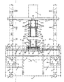
- the figure presents the plan of a building, where the method for loadbearing wall replacement is applied.
- recess 2 is created, at the bottom of which micro piles 3 are driven until reaching a loadbearing soil layer 4.
- Recess 2 is created with a width that makes it possible for the machine that drives micro piles 3 to move and work.
- recess 2 is supported with a temporary supporting wall 6. If the level of surface water 7 reaches over the bottom of recess 2, surface water is removed from recess 2 during construction works.
- micro piles 3 After micro piles 3 are driven in, the on-pile foundation 8 from reinforced concrete is built on the piles.
- the on-pile foundation 8 from reinforced concrete is reinforced near the upper and lower level by means of steel fittings 9. Steel fittings 9 are pre-tensioned.
- Recess 2 micro piles 3 and on-pile foundation 8 are initially created on one side of loadbearing wall 1 and then to the other side of loadbearing wall 1.
- Recess 2 is created at such distance from loadbearing wall 1 that the stability of foundation 10 of the loadbearing wall would be ensured, and taking into account supporting wall 6 of recess 2.
- Cross-beams 12 that are rested on on-pile foundation 8, are installed under loadbearing columns 11 that support loadbearing wall 1. Cross-beams 12 are installed beneath the lower level 14 of the rough floor 13.
- recess 2 is backfilled and compacted with mineral soil to compacting degree 1.00.
- the temporary support walls 6 of recess 2 are removed.
- An elastic layer 15 is installed between cross-beams 12 and the lower level 14 of the rough floor 13 in order to compensate various deformations in rough floor 13 and cross-beams 12 as a result of moisture and temperature fluctuations.
- a temporary opening 16 with the width of cross-beams 12 is left in rough floor 13 for the installation of load bearing columns 11.
- load bearing wall 1 After the installation of temporary supports 18, vertical openings are cut into load bearing wall 1 for two adjacent load bearing columns 11 and the columns are installed on cross-beams 12.
- Loadbearing columns 11 are installed on cross-beams 12 by means of load-resistant anchor bolts 19.
- Load-resistant anchor bolts 19 are supplied with pressure nuts 20 for adjusting the height of load bearing columns 11.
- Loadbearing columns 11 are produced from steel tube jacket 21 and concrete core 22. With the interaction between concrete core 22 and steel tube jacket 21, i.e. load bearing column 11, the load bearing column 11 will achieve the optimum load stability and fire resistance.
- load bearing beam 23 is repeated on the other side of load bearing wall 1.
- the gap between load bearing beams 23 is filled with fire resistant and sound insulating material 26, such as with dense rock wool. Then the load bearing wall section 27 under load bearing beams 23 is demolished.
- load bearing beams 23 are covered with a fire retardant and sound insulating material 26, such as dense rock wool boards or fire resistant gypsum boards, and the temporary supports 18 are removed.
- loadbearing columns 11 and load bearing beam 23 are provided with extra tension by means of load-resistant bolts 19 and pressure nuts 20 in order to prevent deformations in loadbearing wall 1 and the load bearing structure 17 of the ceiling.
- loadbearing columns 11 and load bearing beam 23 are covered with fire resistant mixture 29, which will ensure the steel tube jacket 21 and thereby also load bearing column 11 with optimum fire resistance in interaction with concrete core 22.
Landscapes
- Engineering & Computer Science (AREA)
- Architecture (AREA)
- Chemical & Material Sciences (AREA)
- Chemical Kinetics & Catalysis (AREA)
- Electrochemistry (AREA)
- Mechanical Engineering (AREA)
- Civil Engineering (AREA)
- Structural Engineering (AREA)
- Building Environments (AREA)
- Working Measures On Existing Buildindgs (AREA)
Claims (6)
- Verfahren zum Ersetzen einer tragenden Wand in einem Gebäude, das aus einer tragenden Wand, tragenden Säulen, die die tragende Wand unterstützen, dem Fundament der tragenden Wand, der Stahlröhre und Stahlpfähle besteht: Querbalken werden im Fundament der tragenden Wand unter den tragenden Säulen eingebaut, die die tragende Wand unterstützen, gekennzeichnet dadurch,dass
eine Aushöhlung (2) neben der tragenden Wand (1) hergestellt wird, Mikropfähle (3) am Boden der Aushöhlung eingerammt werden bis zur tragenden Schicht (4), und die Aushöhlung (2) mit einer temporären Stützwand (6) unterstützt wird;
das Pfahlfundament (8) auf eingerammte Pfähle (3) gebaut und mit vorgespannter Stahlbewehrung (9) verstärkt wird;
die Aushöhlung (2), die Pfähle (3) und das Pfahlfundament (8) werden zunächst auf einer Seite der tragenden Wand (1) und dann auf der anderen Seite der tragenden Wand (1) hergestellt;
die Querbalken (12) unter tragenden Säulen (11) die die tragende Wand (1) unterstützen, liegen auf dem Pfahlfundament (8), während die Querbalken (1) unter der unteren Oberfläche (14) des Rohestrichs (13) eingebaut werden;
die Aushöhlung (2) aufgefüllt und verdichtet, und die temporären Stützwände (6) der Aushöhlung (2) entfernt werden;
eine elastische Schicht (15) zwischen den Querbalken (12) und der unteren Oberfläche (14) des Rohestrichs eingebaut wird;
die temporären Stützen (18), die die Last der tragenden Strukturen (17) der Decken, der Fussboden und des Pfahlfundaments (8) aufnehmen, eingebaut werden;
vertikale Öffnungen in der tragenden Wand (1) für zwei tragenden Säulen (11) eingeschnitten werden, die auf Querbalken (12) mit Ankerbolzen (19) eingebaut werden, wobei Ankerbolzen mit Druckmuttern (20) versehen werden, die die Höhe der tragenden Säule (11) einstellen;
Öffnungen für tragende Balken (23) in der tragenden Wand (1) bis zur Hälfte deren Stärke eingeschnitten werden, unter der Dachkonstruktion (17), und einer der tragenden Balken (23) auf tragenden Säulen (11) gebaut und die Aussparung zwischen des ersten tragenden Balkens (23) und der Dachkonstruktion (17) durch Stahlkeile (24) gekeilt wird, und die Lücke mit expandierendem Montagebeton (25) ausgefüllt wird;
der zweite tragende Balken (23) auf der anderen Seite der tragenden Wand (1) gebaut wird, wobei der Raum zwischen den tragenden Balken (23) mit einem flammhemmenden und geräuschdämmenden Mittel (26) ausgefüllt und der Abschnitt der tragenden Wand (27) unter tragenden Balken (23) vor dem Bau des anderen tragenden Balkens (23) zerstört wird;
danach der vorherige Einbau der tragenden Säulen (11) und tragenden Balken (23) in anderen Räumen zwischen den Säulen wiederholt wird;
wenn das ganze Säulen-Balkensystem fertig ist, die tragenden Balken (23) mit einem flammhemmenden und geräuschdämmenden Mittel (26) ausgefüllt und die temporären Stützen (18) entfernt werden;
die tragenden Säulen (11) und der tragenden Balken (23) zusätzlich mit Bolzen (19) und Druckmuttern (20) gespannt werden;
nach der Unterstützung der Pfähle (3), des Pfahlfundaments (8) und der Querbalken die Lücke zwischen der tragenden Säule (11) und des Querbalkens (12) mit vorgespanntem Beton (28) ausgefüllt und der Rohestrich (13) fertig gestellt wird. - Verfahren nach Anspruch 1, dadurch gekennzeichnet, dass die Aushöhlung (2) an einem solchen Abstand zur tragenden Wand (1) hergestellt wird, dass die Standsicherheit der tragenden Wand gewährleistet ist, und die Aushöhlung (2) mit einer solchen Breite hergestellt wird, dass es für Maschinen möglich ist, sich in der Aushöhlung zu bewegen und zu arbeiten.
- Verfahren nach Anspruch 1, dadurch gekennzeichnet, dass die Füllung der Ausführung mit mineralischer Erde zu einem Verdichtungsgrad von 1,00 verdichtet wird.
- Verfahren nach Anspruch 1, dadurch gekennzeichnet, dass die tragenden Säulen (11) aus Rohrmantel (21) und Betonkern (22) hergestellt werden.
- Verfahren nach Anspruch 1, dadurch gekennzeichnet, dass Steinwolle und feuerfester Gips als flammhemmende und geräuschdämmende Mittel (26) verwendet werden.
- Verfahren nach Anspruch 1, dadurch gekennzeichnet, dass vor der Fertigstellung der tragenden Säulen (11) und tragenden Balken (23) die tragenden Säulen (11) mit einer feuerbeständigen Mischung (29) bedeckt werden.
Applications Claiming Priority (1)
| Application Number | Priority Date | Filing Date | Title |
|---|---|---|---|
| EEU200900045U EE00888U1 (et) | 2009-05-08 | 2009-05-08 | Kandeseina asendamise meetod |
Publications (3)
| Publication Number | Publication Date |
|---|---|
| EP2251503A2 EP2251503A2 (de) | 2010-11-17 |
| EP2251503A3 EP2251503A3 (de) | 2013-10-30 |
| EP2251503B1 true EP2251503B1 (de) | 2014-10-01 |
Family
ID=41528913
Family Applications (1)
| Application Number | Title | Priority Date | Filing Date |
|---|---|---|---|
| EP10004866.9A Not-in-force EP2251503B1 (de) | 2009-05-08 | 2010-05-07 | Verfahren zum Ersetzen einer tragenden Wand |
Country Status (2)
| Country | Link |
|---|---|
| EP (1) | EP2251503B1 (de) |
| EE (1) | EE00888U1 (de) |
Cited By (1)
| Publication number | Priority date | Publication date | Assignee | Title |
|---|---|---|---|---|
| CN104863380A (zh) * | 2015-05-20 | 2015-08-26 | 中建三局第二建设工程有限责任公司 | 一种在原有建筑隔震支座整体置换系统及施工方法 |
Families Citing this family (10)
| Publication number | Priority date | Publication date | Assignee | Title |
|---|---|---|---|---|
| RU2584989C1 (ru) * | 2015-03-11 | 2016-05-27 | Федеральное государственное автономное образовательное учреждение высшего образования "Сибирский федеральный университет" | Устройство для усиления несущих конструкций |
| CN107724559B (zh) * | 2017-10-23 | 2019-07-05 | 南京百西思建筑科技有限公司 | 既有建筑隔震加固施工流程 |
| CN109403654B (zh) * | 2018-11-05 | 2021-03-26 | 广东赛力克建筑技术工程有限公司 | 一种既有建筑物结构的托换加固方法 |
| CN111962901A (zh) * | 2020-08-14 | 2020-11-20 | 山东金城建设有限公司 | 既有砌体结构改造施工方法 |
| CN112482819B (zh) * | 2020-12-07 | 2024-12-27 | 苏州达康建筑科技有限公司 | 混凝土竖向构件的替换方法及其替换结构 |
| CN114457842A (zh) * | 2022-02-24 | 2022-05-10 | 郎溪浩稳建设工程有限公司 | 一种明挖法地铁建设结构力学挡土墙加固梁柱 |
| CN114517596B (zh) * | 2022-03-10 | 2024-04-02 | 山东省建筑科学研究院有限公司 | 一种预制装配式墙板与砌体墙的预应力销键连接结构 |
| CN117166814A (zh) * | 2023-09-05 | 2023-12-05 | 北京市建筑工程研究院有限责任公司 | 一种多高层钢筋混凝土承重墙自支撑结构及其施工方法 |
| CN117868556B (zh) * | 2024-03-13 | 2024-06-25 | 北京建工四建工程建设有限公司 | 一种以建筑自身为承重构件的建筑拆改支撑系统 |
| CN117967092B (zh) * | 2024-03-13 | 2024-09-17 | 北京建工四建工程建设有限公司 | 一种无需对建筑临时支撑的建筑拆改施工方法 |
Family Cites Families (4)
| Publication number | Priority date | Publication date | Assignee | Title |
|---|---|---|---|---|
| JPS57205629A (en) * | 1981-06-09 | 1982-12-16 | Kajima Corp | Building structure |
| JP2002227303A (ja) | 2001-01-29 | 2002-08-14 | Takenaka Komuten Co Ltd | 建築物の構造 |
| DE20317225U1 (de) * | 2003-11-08 | 2004-01-08 | Schöck Entwicklungsgesellschaft mbH | Bauelement zur Druckkraftübertragung und Vorrichtung zur Einbringung einer Vorspannung zwischen zwei Gebäudeteile |
| GB0409215D0 (en) * | 2004-04-24 | 2004-05-26 | Janjic Srdan | Tensioned structural propping system |
-
2009
- 2009-05-08 EE EEU200900045U patent/EE00888U1/xx not_active IP Right Cessation
-
2010
- 2010-05-07 EP EP10004866.9A patent/EP2251503B1/de not_active Not-in-force
Cited By (1)
| Publication number | Priority date | Publication date | Assignee | Title |
|---|---|---|---|---|
| CN104863380A (zh) * | 2015-05-20 | 2015-08-26 | 中建三局第二建设工程有限责任公司 | 一种在原有建筑隔震支座整体置换系统及施工方法 |
Also Published As
| Publication number | Publication date |
|---|---|
| EE00888U1 (et) | 2010-01-15 |
| EP2251503A3 (de) | 2013-10-30 |
| EP2251503A2 (de) | 2010-11-17 |
Similar Documents
| Publication | Publication Date | Title |
|---|---|---|
| EP2251503B1 (de) | Verfahren zum Ersetzen einer tragenden Wand | |
| CN112502161B (zh) | 深基坑支护体系施工方法 | |
| CN112962663A (zh) | 深基础狭窄外围护空间施工方法 | |
| JP2018009336A (ja) | 地下空間構築方法 | |
| KR102396786B1 (ko) | 기존 지하 외벽의 보강을 통한 신설 건물의 지하 증축 및 역타 공법 | |
| JP5865567B2 (ja) | 連結用スラブ及びその構築方法 | |
| CN113697640B (zh) | 既有多层建筑整体装配式加装电梯的成品井道及施工方法 | |
| KR20210090100A (ko) | 지하구조물이 벽식구조인 건물에서 가설전이구조물을 이용하여 조기지상골조 착수가 가능한 공기단축형 역타공법 및 구조 | |
| CN109267578B (zh) | 一种斜面素混凝土结构及其施工方法 | |
| KR101483865B1 (ko) | 합성구조의 띠장을 이용한 지하구조물시공방법 | |
| JP7565256B2 (ja) | 建物の建て替え方法 | |
| JP2006502324A (ja) | プレストレスト仮設工法 | |
| JP2003003690A (ja) | 免震建物および既存建物の免震化工法 | |
| CN114319437A (zh) | 一种暗挖建造明挖增层竖井处挡墙结构的施工方法 | |
| JP2006002428A (ja) | 既存床の補強工法および既存建物の免震化工法 | |
| KR102181416B1 (ko) | 내진용 alc 주택 시공방법 | |
| KR102789166B1 (ko) | 뜬구조를 이용한 지하주차장 기둥 이설 방법 | |
| CN118856100B (zh) | 一种顶管始发井顶管传力分配体系及其施工方法 | |
| KR100767953B1 (ko) | 흙막이 합벽과 외곽 보의 이격 공법 | |
| CN216142027U (zh) | 一种高性能混凝土预制导墙结构 | |
| KR102817109B1 (ko) | 지하주차장 리모델링 공사를 위한 가설 기둥 지지 구조 | |
| CN221345616U (zh) | 一种预制自沉基坑围护墙板 | |
| EP2345779B1 (de) | Verfahren zur Herstellung einer Öffnung in einem Fußboden | |
| JP2571426B2 (ja) | 山止め壁の構築方法 | |
| KR102776513B1 (ko) | 베이스부재를 이용한 지하주차장 리모델링 공사용 가설 기둥 지지 구조 |
Legal Events
| Date | Code | Title | Description |
|---|---|---|---|
| PUAI | Public reference made under article 153(3) epc to a published international application that has entered the european phase |
Free format text: ORIGINAL CODE: 0009012 |
|
| AK | Designated contracting states |
Kind code of ref document: A2 Designated state(s): AL AT BE BG CH CY CZ DE DK EE ES FI FR GB GR HR HU IE IS IT LI LT LU LV MC MK MT NL NO PL PT RO SE SI SK SM TR |
|
| AX | Request for extension of the european patent |
Extension state: BA ME RS |
|
| PUAL | Search report despatched |
Free format text: ORIGINAL CODE: 0009013 |
|
| AK | Designated contracting states |
Kind code of ref document: A3 Designated state(s): AL AT BE BG CH CY CZ DE DK EE ES FI FR GB GR HR HU IE IS IT LI LT LU LV MC MK MT NL NO PL PT RO SE SI SK SM TR |
|
| AX | Request for extension of the european patent |
Extension state: BA ME RS |
|
| RIC1 | Information provided on ipc code assigned before grant |
Ipc: E04G 23/02 20060101AFI20130926BHEP |
|
| 17P | Request for examination filed |
Effective date: 20140221 |
|
| RBV | Designated contracting states (corrected) |
Designated state(s): AL AT BE BG CH CY CZ DE DK EE ES FI FR GB GR HR HU IE IS IT LI LT LU LV MC MK MT NL NO PL PT RO SE SI SK SM TR |
|
| GRAP | Despatch of communication of intention to grant a patent |
Free format text: ORIGINAL CODE: EPIDOSNIGR1 |
|
| INTG | Intention to grant announced |
Effective date: 20140519 |
|
| GRAS | Grant fee paid |
Free format text: ORIGINAL CODE: EPIDOSNIGR3 |
|
| GRAA | (expected) grant |
Free format text: ORIGINAL CODE: 0009210 |
|
| AK | Designated contracting states |
Kind code of ref document: B1 Designated state(s): AL AT BE BG CH CY CZ DE DK EE ES FI FR GB GR HR HU IE IS IT LI LT LU LV MC MK MT NL NO PL PT RO SE SI SK SM TR |
|
| REG | Reference to a national code |
Ref country code: GB Ref legal event code: FG4D |
|
| REG | Reference to a national code |
Ref country code: AT Ref legal event code: REF Ref document number: 689644 Country of ref document: AT Kind code of ref document: T Effective date: 20141015 Ref country code: CH Ref legal event code: EP |
|
| REG | Reference to a national code |
Ref country code: IE Ref legal event code: FG4D |
|
| REG | Reference to a national code |
Ref country code: DE Ref legal event code: R096 Ref document number: 602010019200 Country of ref document: DE Effective date: 20141127 |
|
| REG | Reference to a national code |
Ref country code: NL Ref legal event code: VDEP Effective date: 20141001 |
|
| REG | Reference to a national code |
Ref country code: AT Ref legal event code: MK05 Ref document number: 689644 Country of ref document: AT Kind code of ref document: T Effective date: 20141001 |
|
| REG | Reference to a national code |
Ref country code: LT Ref legal event code: MG4D |
|
| PG25 | Lapsed in a contracting state [announced via postgrant information from national office to epo] |
Ref country code: NL Free format text: LAPSE BECAUSE OF FAILURE TO SUBMIT A TRANSLATION OF THE DESCRIPTION OR TO PAY THE FEE WITHIN THE PRESCRIBED TIME-LIMIT Effective date: 20141001 |
|
| PG25 | Lapsed in a contracting state [announced via postgrant information from national office to epo] |
Ref country code: PT Free format text: LAPSE BECAUSE OF FAILURE TO SUBMIT A TRANSLATION OF THE DESCRIPTION OR TO PAY THE FEE WITHIN THE PRESCRIBED TIME-LIMIT Effective date: 20150202 Ref country code: CZ Free format text: LAPSE BECAUSE OF FAILURE TO SUBMIT A TRANSLATION OF THE DESCRIPTION OR TO PAY THE FEE WITHIN THE PRESCRIBED TIME-LIMIT Effective date: 20141001 Ref country code: IS Free format text: LAPSE BECAUSE OF FAILURE TO SUBMIT A TRANSLATION OF THE DESCRIPTION OR TO PAY THE FEE WITHIN THE PRESCRIBED TIME-LIMIT Effective date: 20150201 Ref country code: ES Free format text: LAPSE BECAUSE OF FAILURE TO SUBMIT A TRANSLATION OF THE DESCRIPTION OR TO PAY THE FEE WITHIN THE PRESCRIBED TIME-LIMIT Effective date: 20141001 Ref country code: NO Free format text: LAPSE BECAUSE OF FAILURE TO SUBMIT A TRANSLATION OF THE DESCRIPTION OR TO PAY THE FEE WITHIN THE PRESCRIBED TIME-LIMIT Effective date: 20150101 Ref country code: LT Free format text: LAPSE BECAUSE OF FAILURE TO SUBMIT A TRANSLATION OF THE DESCRIPTION OR TO PAY THE FEE WITHIN THE PRESCRIBED TIME-LIMIT Effective date: 20141001 Ref country code: FI Free format text: LAPSE BECAUSE OF FAILURE TO SUBMIT A TRANSLATION OF THE DESCRIPTION OR TO PAY THE FEE WITHIN THE PRESCRIBED TIME-LIMIT Effective date: 20141001 |
|
| PG25 | Lapsed in a contracting state [announced via postgrant information from national office to epo] |
Ref country code: SE Free format text: LAPSE BECAUSE OF FAILURE TO SUBMIT A TRANSLATION OF THE DESCRIPTION OR TO PAY THE FEE WITHIN THE PRESCRIBED TIME-LIMIT Effective date: 20141001 Ref country code: LV Free format text: LAPSE BECAUSE OF FAILURE TO SUBMIT A TRANSLATION OF THE DESCRIPTION OR TO PAY THE FEE WITHIN THE PRESCRIBED TIME-LIMIT Effective date: 20141001 Ref country code: PL Free format text: LAPSE BECAUSE OF FAILURE TO SUBMIT A TRANSLATION OF THE DESCRIPTION OR TO PAY THE FEE WITHIN THE PRESCRIBED TIME-LIMIT Effective date: 20141001 Ref country code: AT Free format text: LAPSE BECAUSE OF FAILURE TO SUBMIT A TRANSLATION OF THE DESCRIPTION OR TO PAY THE FEE WITHIN THE PRESCRIBED TIME-LIMIT Effective date: 20141001 Ref country code: GR Free format text: LAPSE BECAUSE OF FAILURE TO SUBMIT A TRANSLATION OF THE DESCRIPTION OR TO PAY THE FEE WITHIN THE PRESCRIBED TIME-LIMIT Effective date: 20150102 Ref country code: CY Free format text: LAPSE BECAUSE OF FAILURE TO SUBMIT A TRANSLATION OF THE DESCRIPTION OR TO PAY THE FEE WITHIN THE PRESCRIBED TIME-LIMIT Effective date: 20141001 Ref country code: HR Free format text: LAPSE BECAUSE OF FAILURE TO SUBMIT A TRANSLATION OF THE DESCRIPTION OR TO PAY THE FEE WITHIN THE PRESCRIBED TIME-LIMIT Effective date: 20141001 |
|
| REG | Reference to a national code |
Ref country code: DE Ref legal event code: R097 Ref document number: 602010019200 Country of ref document: DE |
|
| PG25 | Lapsed in a contracting state [announced via postgrant information from national office to epo] |
Ref country code: SK Free format text: LAPSE BECAUSE OF FAILURE TO SUBMIT A TRANSLATION OF THE DESCRIPTION OR TO PAY THE FEE WITHIN THE PRESCRIBED TIME-LIMIT Effective date: 20141001 Ref country code: RO Free format text: LAPSE BECAUSE OF FAILURE TO SUBMIT A TRANSLATION OF THE DESCRIPTION OR TO PAY THE FEE WITHIN THE PRESCRIBED TIME-LIMIT Effective date: 20141001 Ref country code: EE Free format text: LAPSE BECAUSE OF FAILURE TO SUBMIT A TRANSLATION OF THE DESCRIPTION OR TO PAY THE FEE WITHIN THE PRESCRIBED TIME-LIMIT Effective date: 20141001 Ref country code: DK Free format text: LAPSE BECAUSE OF FAILURE TO SUBMIT A TRANSLATION OF THE DESCRIPTION OR TO PAY THE FEE WITHIN THE PRESCRIBED TIME-LIMIT Effective date: 20141001 |
|
| PLBE | No opposition filed within time limit |
Free format text: ORIGINAL CODE: 0009261 |
|
| STAA | Information on the status of an ep patent application or granted ep patent |
Free format text: STATUS: NO OPPOSITION FILED WITHIN TIME LIMIT |
|
| PG25 | Lapsed in a contracting state [announced via postgrant information from national office to epo] |
Ref country code: IT Free format text: LAPSE BECAUSE OF FAILURE TO SUBMIT A TRANSLATION OF THE DESCRIPTION OR TO PAY THE FEE WITHIN THE PRESCRIBED TIME-LIMIT Effective date: 20141001 |
|
| 26N | No opposition filed |
Effective date: 20150702 |
|
| REG | Reference to a national code |
Ref country code: CH Ref legal event code: PL |
|
| PG25 | Lapsed in a contracting state [announced via postgrant information from national office to epo] |
Ref country code: LI Free format text: LAPSE BECAUSE OF NON-PAYMENT OF DUE FEES Effective date: 20150531 Ref country code: CH Free format text: LAPSE BECAUSE OF NON-PAYMENT OF DUE FEES Effective date: 20150531 Ref country code: LU Free format text: LAPSE BECAUSE OF FAILURE TO SUBMIT A TRANSLATION OF THE DESCRIPTION OR TO PAY THE FEE WITHIN THE PRESCRIBED TIME-LIMIT Effective date: 20150507 Ref country code: MC Free format text: LAPSE BECAUSE OF FAILURE TO SUBMIT A TRANSLATION OF THE DESCRIPTION OR TO PAY THE FEE WITHIN THE PRESCRIBED TIME-LIMIT Effective date: 20141001 |
|
| REG | Reference to a national code |
Ref country code: IE Ref legal event code: MM4A |
|
| PG25 | Lapsed in a contracting state [announced via postgrant information from national office to epo] |
Ref country code: SI Free format text: LAPSE BECAUSE OF FAILURE TO SUBMIT A TRANSLATION OF THE DESCRIPTION OR TO PAY THE FEE WITHIN THE PRESCRIBED TIME-LIMIT Effective date: 20141001 |
|
| PG25 | Lapsed in a contracting state [announced via postgrant information from national office to epo] |
Ref country code: IE Free format text: LAPSE BECAUSE OF NON-PAYMENT OF DUE FEES Effective date: 20150507 |
|
| REG | Reference to a national code |
Ref country code: FR Ref legal event code: PLFP Year of fee payment: 7 |
|
| PGFP | Annual fee paid to national office [announced via postgrant information from national office to epo] |
Ref country code: GB Payment date: 20160526 Year of fee payment: 7 |
|
| PGFP | Annual fee paid to national office [announced via postgrant information from national office to epo] |
Ref country code: FR Payment date: 20160526 Year of fee payment: 7 |
|
| PGFP | Annual fee paid to national office [announced via postgrant information from national office to epo] |
Ref country code: DE Payment date: 20160629 Year of fee payment: 7 |
|
| PG25 | Lapsed in a contracting state [announced via postgrant information from national office to epo] |
Ref country code: MT Free format text: LAPSE BECAUSE OF FAILURE TO SUBMIT A TRANSLATION OF THE DESCRIPTION OR TO PAY THE FEE WITHIN THE PRESCRIBED TIME-LIMIT Effective date: 20141001 |
|
| PG25 | Lapsed in a contracting state [announced via postgrant information from national office to epo] |
Ref country code: BG Free format text: LAPSE BECAUSE OF FAILURE TO SUBMIT A TRANSLATION OF THE DESCRIPTION OR TO PAY THE FEE WITHIN THE PRESCRIBED TIME-LIMIT Effective date: 20141001 Ref country code: SM Free format text: LAPSE BECAUSE OF FAILURE TO SUBMIT A TRANSLATION OF THE DESCRIPTION OR TO PAY THE FEE WITHIN THE PRESCRIBED TIME-LIMIT Effective date: 20141001 Ref country code: HU Free format text: LAPSE BECAUSE OF FAILURE TO SUBMIT A TRANSLATION OF THE DESCRIPTION OR TO PAY THE FEE WITHIN THE PRESCRIBED TIME-LIMIT; INVALID AB INITIO Effective date: 20100507 |
|
| PG25 | Lapsed in a contracting state [announced via postgrant information from national office to epo] |
Ref country code: TR Free format text: LAPSE BECAUSE OF FAILURE TO SUBMIT A TRANSLATION OF THE DESCRIPTION OR TO PAY THE FEE WITHIN THE PRESCRIBED TIME-LIMIT Effective date: 20141001 |
|
| PG25 | Lapsed in a contracting state [announced via postgrant information from national office to epo] |
Ref country code: BE Free format text: LAPSE BECAUSE OF FAILURE TO SUBMIT A TRANSLATION OF THE DESCRIPTION OR TO PAY THE FEE WITHIN THE PRESCRIBED TIME-LIMIT Effective date: 20141001 |
|
| REG | Reference to a national code |
Ref country code: DE Ref legal event code: R119 Ref document number: 602010019200 Country of ref document: DE |
|
| GBPC | Gb: european patent ceased through non-payment of renewal fee |
Effective date: 20170507 |
|
| REG | Reference to a national code |
Ref country code: FR Ref legal event code: ST Effective date: 20180131 |
|
| PG25 | Lapsed in a contracting state [announced via postgrant information from national office to epo] |
Ref country code: DE Free format text: LAPSE BECAUSE OF NON-PAYMENT OF DUE FEES Effective date: 20171201 Ref country code: GB Free format text: LAPSE BECAUSE OF NON-PAYMENT OF DUE FEES Effective date: 20170507 |
|
| PG25 | Lapsed in a contracting state [announced via postgrant information from national office to epo] |
Ref country code: FR Free format text: LAPSE BECAUSE OF NON-PAYMENT OF DUE FEES Effective date: 20170531 |
|
| PG25 | Lapsed in a contracting state [announced via postgrant information from national office to epo] |
Ref country code: MK Free format text: LAPSE BECAUSE OF FAILURE TO SUBMIT A TRANSLATION OF THE DESCRIPTION OR TO PAY THE FEE WITHIN THE PRESCRIBED TIME-LIMIT Effective date: 20141001 |
|
| PG25 | Lapsed in a contracting state [announced via postgrant information from national office to epo] |
Ref country code: AL Free format text: LAPSE BECAUSE OF FAILURE TO SUBMIT A TRANSLATION OF THE DESCRIPTION OR TO PAY THE FEE WITHIN THE PRESCRIBED TIME-LIMIT Effective date: 20141001 |