EP2250356B1 - Speicherung elektrischer energie mit wärmespeicher und rückverstromung mittels eines thermodynamischen kreisprozesses - Google Patents
Speicherung elektrischer energie mit wärmespeicher und rückverstromung mittels eines thermodynamischen kreisprozesses Download PDFInfo
- Publication number
- EP2250356B1 EP2250356B1 EP09718910A EP09718910A EP2250356B1 EP 2250356 B1 EP2250356 B1 EP 2250356B1 EP 09718910 A EP09718910 A EP 09718910A EP 09718910 A EP09718910 A EP 09718910A EP 2250356 B1 EP2250356 B1 EP 2250356B1
- Authority
- EP
- European Patent Office
- Prior art keywords
- heat
- thermal storage
- storage unit
- gas turbine
- heat exchanger
- Prior art date
- Legal status (The legal status is an assumption and is not a legal conclusion. Google has not performed a legal analysis and makes no representation as to the accuracy of the status listed.)
- Active
Links
Images

Classifications
-
- F—MECHANICAL ENGINEERING; LIGHTING; HEATING; WEAPONS; BLASTING
- F02—COMBUSTION ENGINES; HOT-GAS OR COMBUSTION-PRODUCT ENGINE PLANTS
- F02C—GAS-TURBINE PLANTS; AIR INTAKES FOR JET-PROPULSION PLANTS; CONTROLLING FUEL SUPPLY IN AIR-BREATHING JET-PROPULSION PLANTS
- F02C1/00—Gas-turbine plants characterised by the use of hot gases or unheated pressurised gases, as the working fluid
- F02C1/04—Gas-turbine plants characterised by the use of hot gases or unheated pressurised gases, as the working fluid the working fluid being heated indirectly
- F02C1/05—Gas-turbine plants characterised by the use of hot gases or unheated pressurised gases, as the working fluid the working fluid being heated indirectly characterised by the type or source of heat, e.g. using nuclear or solar energy
-
- F—MECHANICAL ENGINEERING; LIGHTING; HEATING; WEAPONS; BLASTING
- F01—MACHINES OR ENGINES IN GENERAL; ENGINE PLANTS IN GENERAL; STEAM ENGINES
- F01D—NON-POSITIVE DISPLACEMENT MACHINES OR ENGINES, e.g. STEAM TURBINES
- F01D15/00—Adaptations of machines or engines for special use; Combinations of engines with devices driven thereby
-
- F—MECHANICAL ENGINEERING; LIGHTING; HEATING; WEAPONS; BLASTING
- F01—MACHINES OR ENGINES IN GENERAL; ENGINE PLANTS IN GENERAL; STEAM ENGINES
- F01K—STEAM ENGINE PLANTS; STEAM ACCUMULATORS; ENGINE PLANTS NOT OTHERWISE PROVIDED FOR; ENGINES USING SPECIAL WORKING FLUIDS OR CYCLES
- F01K13/00—General layout or general methods of operation of complete plants
- F01K13/006—Auxiliaries or details not otherwise provided for
-
- F—MECHANICAL ENGINEERING; LIGHTING; HEATING; WEAPONS; BLASTING
- F01—MACHINES OR ENGINES IN GENERAL; ENGINE PLANTS IN GENERAL; STEAM ENGINES
- F01K—STEAM ENGINE PLANTS; STEAM ACCUMULATORS; ENGINE PLANTS NOT OTHERWISE PROVIDED FOR; ENGINES USING SPECIAL WORKING FLUIDS OR CYCLES
- F01K23/00—Plants characterised by more than one engine delivering power external to the plant, the engines being driven by different fluids
- F01K23/02—Plants characterised by more than one engine delivering power external to the plant, the engines being driven by different fluids the engine cycles being thermally coupled
- F01K23/06—Plants characterised by more than one engine delivering power external to the plant, the engines being driven by different fluids the engine cycles being thermally coupled combustion heat from one cycle heating the fluid in another cycle
- F01K23/10—Plants characterised by more than one engine delivering power external to the plant, the engines being driven by different fluids the engine cycles being thermally coupled combustion heat from one cycle heating the fluid in another cycle with exhaust fluid of one cycle heating the fluid in another cycle
-
- F—MECHANICAL ENGINEERING; LIGHTING; HEATING; WEAPONS; BLASTING
- F01—MACHINES OR ENGINES IN GENERAL; ENGINE PLANTS IN GENERAL; STEAM ENGINES
- F01K—STEAM ENGINE PLANTS; STEAM ACCUMULATORS; ENGINE PLANTS NOT OTHERWISE PROVIDED FOR; ENGINES USING SPECIAL WORKING FLUIDS OR CYCLES
- F01K3/00—Plants characterised by the use of steam or heat accumulators, or intermediate steam heaters, therein
- F01K3/18—Plants characterised by the use of steam or heat accumulators, or intermediate steam heaters, therein having heaters
- F01K3/186—Plants characterised by the use of steam or heat accumulators, or intermediate steam heaters, therein having heaters using electric heat
-
- F—MECHANICAL ENGINEERING; LIGHTING; HEATING; WEAPONS; BLASTING
- F02—COMBUSTION ENGINES; HOT-GAS OR COMBUSTION-PRODUCT ENGINE PLANTS
- F02C—GAS-TURBINE PLANTS; AIR INTAKES FOR JET-PROPULSION PLANTS; CONTROLLING FUEL SUPPLY IN AIR-BREATHING JET-PROPULSION PLANTS
- F02C6/00—Plural gas-turbine plants; Combinations of gas-turbine plants with other apparatus; Adaptations of gas-turbine plants for special use
- F02C6/14—Gas-turbine plants having means for storing energy, e.g. for meeting peak loads
-
- F—MECHANICAL ENGINEERING; LIGHTING; HEATING; WEAPONS; BLASTING
- F05—INDEXING SCHEMES RELATING TO ENGINES OR PUMPS IN VARIOUS SUBCLASSES OF CLASSES F01-F04
- F05D—INDEXING SCHEME FOR ASPECTS RELATING TO NON-POSITIVE-DISPLACEMENT MACHINES OR ENGINES, GAS-TURBINES OR JET-PROPULSION PLANTS
- F05D2220/00—Application
- F05D2220/60—Application making use of surplus or waste energy
-
- F—MECHANICAL ENGINEERING; LIGHTING; HEATING; WEAPONS; BLASTING
- F05—INDEXING SCHEMES RELATING TO ENGINES OR PUMPS IN VARIOUS SUBCLASSES OF CLASSES F01-F04
- F05D—INDEXING SCHEME FOR ASPECTS RELATING TO NON-POSITIVE-DISPLACEMENT MACHINES OR ENGINES, GAS-TURBINES OR JET-PROPULSION PLANTS
- F05D2220/00—Application
- F05D2220/60—Application making use of surplus or waste energy
- F05D2220/64—Application making use of surplus or waste energy for domestic central heating or production of electricity
-
- Y—GENERAL TAGGING OF NEW TECHNOLOGICAL DEVELOPMENTS; GENERAL TAGGING OF CROSS-SECTIONAL TECHNOLOGIES SPANNING OVER SEVERAL SECTIONS OF THE IPC; TECHNICAL SUBJECTS COVERED BY FORMER USPC CROSS-REFERENCE ART COLLECTIONS [XRACs] AND DIGESTS
- Y02—TECHNOLOGIES OR APPLICATIONS FOR MITIGATION OR ADAPTATION AGAINST CLIMATE CHANGE
- Y02E—REDUCTION OF GREENHOUSE GAS [GHG] EMISSIONS, RELATED TO ENERGY GENERATION, TRANSMISSION OR DISTRIBUTION
- Y02E20/00—Combustion technologies with mitigation potential
- Y02E20/16—Combined cycle power plant [CCPP], or combined cycle gas turbine [CCGT]
Definitions
- the invention relates to a device or a method for using excess capacity in the power grid.
- the supply of controllable renewable energies can be addressed in various ways: The fluctuating supply can be compensated for by increasing or decreasing the capacity of conventional power plants, and any renewable energy could not be fed into the grid at all. that, for example, wind turbines are switched off, or the energy could be stored in an energy storage system, ie in pumped storage power plants, compressed air storage power plants or batteries with possibly high plant complexity and high costs.
- the EP 1 577 548 A1 and the EP 1 577 549 A1 describe a device and method for storing energy and power generation. With renewable energy such as wind or solar energy generated electrical energy heats a heat storage. If necessary, the heat is used in the heat storage to generate steam that is fed directly to a thermodynamic process in a steam turbine, the steam generation is optionally complemented conventionally.
- the US 5,384,489 describes a device in which electrical energy is generated by wind energy, with which a heating element is operated to heat a fluid in a storage tank, and a device to withdraw the stored energy from the tank again.
- the from the storage tank taken energy is used for space heating / space cooling, for cooling in general, for desalination, but preferably for steam generation to generate electricity.
- the object of the invention is to propose an improved device and an improved method for using excess capacity in the power grid.
- a disadvantage of the prior art devices and methods is the quality and quantity of steam generated in the heat accumulator, which is not always sufficient for operating a steam turbine, making conventional after-firing necessary.
- prior art devices and methods in power generation are limited to one medium, namely steam.
- the inventive device wants to use the excess capacity in the power grid for a number of different heat consumers and therefore provides a heat storage and a heating element for storing energy from the mains in the heat storage and a heat exchanger with a primary side and a secondary side before, the primary side for the removal of heat is thermally coupled to the heat accumulator from the heat accumulator and wherein the secondary side is connected in a power plant, wherein the power plant, in which the heat exchanger is connected, comprises a gas turbine and the secondary side of the heat exchanger (11) is connected in the gas turbine (13).
- the heat storage is therefore not used to generate steam that is fed directly to a steam turbine.
- the heat exchanger for air preheating is connected on the secondary side in an air supply line of a burner.
- the heat exchanger is connected on the secondary side in a fuel supply line to preheat the fuel.
- the heat exchanger is connected on the secondary side in the flow of combustion gases to their reheat.
- the heat exchanger can also be connected in a power plant, which also contains a steam turbine in addition to a gas turbine.
- the power plant is a gas and steam plant, which comprises a heat recovery steam generator for generating steam for the steam turbine by means of heat from the exhaust gases of the gas turbine.
- a high energy yield can also be achieved by reheating the exhaust gas flow in a turbine of a gas turbine.
- FIG. 1 describes the inventive method for using overcapacities in the power grid. If, at a time t1, the generated power 1 in the network exceeds the consumption 3, the excess supply 2 of electrical energy is stored directly via a heating element in a heat storage, for example a salt storage or concrete heat storage 4.
- a heat storage for example a salt storage or concrete heat storage 4.
- the heat from the heat storage is removed and a heat exchanger whose primary side is thermally coupled to the heat accumulator and the secondary side is connected in a gas turbine of a power plant, fed to a power plant 5, so the power 6 generated at the time t2 covers the demand 7 at the time t2.
- FIG. 2 shows the essential components of the inventive device for the use of excess capacity in the power grid. Via a heating element 8 9 electrical energy can be stored directly in the heat storage 10 from the power grid.
- the primary side of the heat exchanger 11 is thermally coupled to the heat accumulator 10.
- the secondary side of the heat exchanger 11 is connected in a gas turbine 13 (not shown) of a power plant 12.
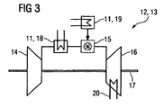
- the power plant 12 shows a gas turbine 13 and includes a compressor 14 for compressing the air, which is then fed to a combustion chamber 15 and is burned with fuel.
- the hot combustion gases drive the turbine 16, which is coupled via a shaft 17 to the compressor 14.
- Heat from the heat accumulator 10 can be used via heat exchanger 11 both for preheating 18 of the compressed air, as well as for fuel preheating 19.
- the combustion chamber 15 is completely switched off and the turbine 16 is driven only by the heated air via a heat exchanger 11 compressed air.
- a reheating 20 takes place in the region of the turbine 16.
Landscapes
- Engineering & Computer Science (AREA)
- Chemical & Material Sciences (AREA)
- Combustion & Propulsion (AREA)
- Mechanical Engineering (AREA)
- General Engineering & Computer Science (AREA)
- Physics & Mathematics (AREA)
- Life Sciences & Earth Sciences (AREA)
- High Energy & Nuclear Physics (AREA)
- Sustainable Development (AREA)
- Sustainable Energy (AREA)
- Engine Equipment That Uses Special Cycles (AREA)
Description
- Die Erfindung betrifft eine Vorrichtung bzw. ein Verfahren zur Nutzung von Überkapazitäten im Stromnetz.
- Im elektrischen Netz müssen die erzeugte Leistung und der Verbrauch immer im Gleichgewicht stehen. Durch den starken Ausbau erneuerbarer Energien stehen zeitweise starke Überkapazitäten zur Verfügung. Dem Überangebot an kontrollierbaren erneuerbaren Energien kann auf verschiedene Weise begegnet werden: Das fluktuierende Angebot kann durch Leistungssteigerung beziehungsweise -minderung konventioneller Kraftwerke ausgeglichen werden, anfallende erneuerbare Energie könnte erst gar nicht ins Netz eingespeist werden, d.h. dass beispielsweise Windturbinen abgeschaltet werden, oder die Energie könnte in ein Energiespeichersystem eingespeichert werden, also in Pumpspeicherkraftwerke, Druckluftspeicherkraftwerke oder Batterien mit unter Umständen hoher Anlagenkomplexität und hohen Kosten.
- Die
EP 1 577 548 A1 und dieEP 1 577 549 A1 beschreiben eine Vorrichtung und eine Methode zur Speicherung von Energie und zur Stromerzeugung. Mit aus erneuerbaren Energien wie Windbeziehungsweise Sonnenenergie erzeugter elektrischer Energie wird ein Wärmespeicher erwärmt. Bei Bedarf wird die Wärme im Wärmespeicher genutzt, um Dampf zu erzeugen, der direkt einem thermodynamischen Prozess in einer Dampfturbine zugeführt wird, wobei die Dampferzeugung gegebenenfalls konventionell ergänzt wird. - Die
US 5,384,489 beschreibt eine Vorrichtung bei der durch Windenergie elektrische Energie erzeugt wird, mit der ein Heizelement betrieben wird, um ein Fluid in einem Speichertank aufzuheizen, sowie eine Vorrichtung, um die gespeicherte Energie aus dem Tank wieder zu entnehmen. Die aus dem Speichertank entnommene Energie wird zur Raumheizung/Raumkühlung, zum Kühlen allgemein, zur Entsalzung, vorzugsweise jedoch für die Dampferzeugung zur Erzeugung von elektrischem Strom verwendet. - Aufgabe der Erfindung ist es, eine verbesserte Vorrichtung und ein verbessertes Verfahren zur Nutzung von Überkapazitäten im Stromnetz vorzuschlagen.
- Diese Aufgabe wird erfindungsgemäß gelöst durch die Merkmale des Patentansprüche 1 und 12.
- Weitere vorteilhafte Ausführungsformen sind in den Unteransprüchen genannt.
- Ein Nachteil der Vorrichtungen und der Verfahren des Standes der Technik ist die zum Betrieb einer Dampfturbine nicht immer ausreichende Qualität und auch Quantität des im Wärmespeicher erzeugten Dampfes, wodurch eine konventionelle Nachfeuerung notwendig wird. Außerdem beschränken sich Vorrichtungen und Verfahren des Standes der Technik bei der Stromerzeugung auf ein Medium, nämlich Dampf.
- Die erfinderische Vorrichtung hingegen will die Überkapazitäten im Stromnetz für eine Reihe verschiedener Wärmeverbraucher nutzen und sieht daher einen Wärmespeicher und ein Heizelement zur Speicherung von Energie aus dem Stromnetz im Wärmespeicher sowie einen Wärmetauscher mit einer Primärseite und einer Sekundärseite vor, wobei die Primärseite zur Ausspeicherung von Wärme aus dem wärmespeicher thermisch an den Wärmespeicher angekoppelt ist und wobei die Sekundärseite in eine Kraftwerksanlage geschaltet ist, wobei die Kraftwerksanlage, in die der Wärmetauscher geschaltet ist, eine Gasturbine umfasst und die Sekundärseite des Wärmetauschers (11) in die Gasturbine (13) geschaltet ist.
- Der Wärmespeicher wird also nicht zur Erzeugung von Dampf verwendet, der direkt einer Dampfturbine zugeführt wird.
- In einer vorteilhaften Ausgestaltung der Erfindung ist der Wärmetauscher zur Luftvorwärmung sekundärseitig in eine Luftzufuhrleitung eines Brenners geschaltet.
- Es ist ebenfalls vorteilhaft, wenn der Wärmetauscher sekundärseitig in eine Brennstoffzufuhrleitung geschaltet ist, um den Brennstoff vorzuwärmen.
- Es ist außerdem zweckmäßig, wenn der Wärmetauscher sekundärseitig in den Strom der Verbrennungsgase zu deren Zwischenüberhitzung geschaltet ist.
- In einer weiteren vorteilhaften Ausgestaltung der Erfindung kann der Wärmetauscher aber auch in eine Kraftwerksanlage geschaltet sein, die neben einer Gasturbine auch eine Dampfturbine enthält.
- In einer besonders vorteilhaften Kombination ist die Kraftwerksanlage eine GuD-Anlage, die einen Abhitzedampferzeuger zur Erzeugung von Dampf für die Dampfturbine mittels Wärme aus den Abgasen der Gasturbine umfasst.
- Im erfinderischen Verfahren wird zur Nutzung von überkapazitäten im Stromnetz im Falle eines überangebots an Energie diese direkt über ein Heizelement in einen Wärmespeicher eingebracht und im Entladungsfall dieses Wärmespeichers die Wärme aus dem Wärmespeicher entnommenen und über einem Wärmetansderprozess indirekt in einen thermodynamischen kreisprozess eingekoppelt wird, wobei elektrische Energie erzeugt wird und wobei die Wärme aus dem Wärmespeicher einer Gasturbine zugeführt wird, beispielsweise zur Vorwärmung von Luft in einer Luftzufuhrleitung einer Brennkammer einerGasturbinenanlage, verwendet wird, oder mit Wärme aus dem Wärmespeicher Gasturbinen- Brennstoff vorgewärmt wird.
- Beide Vorwärmungen reduzieren den Brennstoffverbrauch. Bei nahezu gleichbleibender abgegebener Leistung der Gasturbine führt die Vorwärmung somit zu einer Erhöhung des Gesamtwirkungsgrades der Gasturbinenanlage.
- Eine hohe Energieausbeute kann auch dadurch erreicht werden, dass der Abgasstrom in einer Turbine einer Gasturbine zwischenüberhitzt wird.
- Nachfolgend wird die Erfindung beispielhaft anhand der Zeichnungen näher erläutert. Es zeigen:
- FIG 1
- schematisch das Konzept für die Speicherung von elektrischer Energie mit Wärmespeicher und Rückverstromung mittels eines thermodynamischen Kreisprozesses,
- FIG 2
- schematisch die erfinderische Vorrichtung mit Heizelement, Wärmespeicher und Wärmetauscher und
- FIG 3
- eine Gasturbinenanlage mit Luftvorwärmung, Brennstoffvorwärmung und Zwischenüberhitzung.
- Im Wesentlichen gleich bleibende Elemente werden grundsätzlich mit den gleichen Bezugszeichen beziffert.
-
FIG 1 beschreibt das erfinderische Verfahren zur Nutzung von Überkapazitäten im Stromnetz. Übersteigt zu einem Zeitpunkt t1 die erzeugte Leistung 1 im Netz den Verbrauch 3, wird das Überangebot 2 an elektrischer Energie direkt über ein Heizelement in einen Wärmespeicher, zum Beispiel einen Salzspeicher oder Betonwärmespeicher, eingespeichert 4. - Im Entladungsfall dieses Energiespeichersystems, beispielsweise bei erhöhtem Leistungsbedarf im Stromnetz, wird die Wärme aus dem Wärmespeicher wieder entnommen und über einen Wärmetauscher, dessen Primärseite thermisch an den Wärmespeicher angekoppelt ist und dessen Sekundärseite in eine Gasturbine einer Kraftwerksanlage geschaltet ist, einer Kraftwerksanlage zugeführt 5, so dass die zum Zeitpunkt t2 erzeugte Leistung 6 den Bedarf 7 zum Zeitpunkt t2 deckt.
-
FIG 2 zeigt die wesentlichen Komponenten der erfinderischen Vorrichtung zur Nutzung von Überkapazitäten im Stromnetz. Über ein Heizelement 8 kann aus dem Stromnetz 9 elektrische Energie direkt in den Wärmespeicher 10 eingespeichert werden. Die Primärseite des Wärmetauschers 11 ist thermisch an den Wärmespeicher 10 gekoppelt. Die Sekundärseite des Wärmetauschers 11 ist in eine Gasturbine 13 (nicht gezeigt) einer Kraftwerksanlage 12 geschaltet. - Die Kraftwerksanlage 12 gemäß
FIG 3 zeigt eine Gasturbine 13 und umfasst einen Verdichter 14 zum Verdichten der Luft, welche dann einer Brennkammer 15 zugeführt wird und mit Brennstoff verbrannt wird. Die heißen Verbrennungsgase treiben die Turbine 16 an, die über eine Welle 17 mit dem Verdichter 14 gekoppelt ist. Wärme aus dem Wärmespeicher 10 kann über Wärmetauscher 11 sowohl zur Vorwärmung 18 der Druckluft, als auch zur Brennstoffvorwärmung 19 verwendet werden. - Optional wird die Brennkammer 15 vollständig abgeschaltet und die Turbine 16 lediglich durch die über einen Wärmetauscher 11 erwärmte komprimierte Luft angetrieben. Zweckmäßigerweise erfolgt eine Zwischenüberhitzung 20 im Bereich der Turbine 16.
Claims (9)
- Vorrichtung zur Nutzung von Überkapazitäten im Stromnetz (9), umfassend einen Wärmespeicher (10), ein Heizelement (8) zur Speicherung von Energie aus dem Stromnetz (9) im Wärmespeicher (10) und einen Wärmetauscher (11) mit einer Primärseite und einer Sekundärseite, wobei die Primärseite zur Ausspeicherung von Wärme aus dem Wärmespeicher (10) thermisch an den Wärmespeicher (10) angekoppelt ist und wobei die Sekundärseite in eine Kraftwerksanlage (12) geschaltet ist, dadurch gekennzeichnet, dass die Kraftwerksanlage (12) eine Gasturbine (13) umfasst und die Sekundärseite des Wärmetauschers (11) in die Gasturbine (13) geschaltet ist.
- Die Vorrichtung nach Anspruch 1, wobei der Wärmetauscher (11) zur Luftvorwärmung sekundärseitig in eine Luftzufuhrleitung einer Brennkammer (15) der Gasturbine (13) geschaltet ist.
- Die Vorrichtung nach Anspruch 1 oder 2, wobei der Wärmetauscher (11) zur Brennstoffvorwärmung sekundärseitig in eine Brennstoffzufuhrleitung zur Brennkammer (15) der Gasturbine (13) geschaltet ist.
- Die Vorrichtung nach einem der Ansprüche 1 bis 3, wobei der Wärmetauscher (11) zur Zwischenüberhitzung sekundärseitig in den Abgasstrom in einer Turbine (16) der Gasturbine (13) geschaltet ist.
- Die Vorrichtung nach einem der vorhergehenden Ansprüche, wobei die Kraftwerksanlage (12) auch eine Dampfturbine (26) umfasst.
- Die Vorrichtung nach einem der vorhergehenden Ansprüche, wobei die Kraftwerksanlage eine GuD-Anlage ist und einen Abhitzedampferzeuger umfasst.
- Verfahren zur Nutzung von Überkapazitäten im Stromnetz, bei dem im Falle eines Überangebots an Energie diese direkt über ein Heizelement in einen Wärmespeicher eingebracht wird und im Entladungsfall dieses Wärmespeichers die Wärme aus dem Wärmespeicher entnommen und über einen Wärmetauscherprozess indirekt in einen thermodynamischen Kreisprozess eingekoppelt wird, wobei elektrische Energie erzeugt wird, dadurch gekennzeichnet, dass die Wärme aus dem Wärmespeicher einer Gasturbine zugeführt wird.
- Verfahren nach Anspruch 7, wobei die Wärme aus dem Wärmespeicher zur Vorwärmung von Luft in einer Luftzufuhrleitung einer Brennkammer der Gasturbine verwendet wird oder mit Wärme aus dem Wärmespeicher Gasturbinen- Brennstoff vorgewärmt wird.
- Verfahren nach Anspruch 7 oder 8, wobei auch ein Abgasstrom in einer Turbine einer Gasturbine mit Wärme aus dem Wärmespeicher zwischenüberhitzt wird.
Priority Applications (1)
| Application Number | Priority Date | Filing Date | Title |
|---|---|---|---|
| EP09718910A EP2250356B1 (de) | 2008-03-12 | 2009-03-05 | Speicherung elektrischer energie mit wärmespeicher und rückverstromung mittels eines thermodynamischen kreisprozesses |
Applications Claiming Priority (3)
| Application Number | Priority Date | Filing Date | Title |
|---|---|---|---|
| EP08004589A EP2101051A1 (de) | 2008-03-12 | 2008-03-12 | Speicherung elektrischer Energie mit Wärmespeicher und Rückverstromung mittels eines thermodynamischen Kreisprozesses |
| PCT/EP2009/052604 WO2009112421A1 (de) | 2008-03-12 | 2009-03-05 | Speicherung elektrischer energie mit wärmespeicher und rückverstromung mittels eines thermodynamischen kreisprozesses |
| EP09718910A EP2250356B1 (de) | 2008-03-12 | 2009-03-05 | Speicherung elektrischer energie mit wärmespeicher und rückverstromung mittels eines thermodynamischen kreisprozesses |
Publications (2)
| Publication Number | Publication Date |
|---|---|
| EP2250356A1 EP2250356A1 (de) | 2010-11-17 |
| EP2250356B1 true EP2250356B1 (de) | 2013-02-27 |
Family
ID=39645361
Family Applications (2)
| Application Number | Title | Priority Date | Filing Date |
|---|---|---|---|
| EP08004589A Withdrawn EP2101051A1 (de) | 2008-03-12 | 2008-03-12 | Speicherung elektrischer Energie mit Wärmespeicher und Rückverstromung mittels eines thermodynamischen Kreisprozesses |
| EP09718910A Active EP2250356B1 (de) | 2008-03-12 | 2009-03-05 | Speicherung elektrischer energie mit wärmespeicher und rückverstromung mittels eines thermodynamischen kreisprozesses |
Family Applications Before (1)
| Application Number | Title | Priority Date | Filing Date |
|---|---|---|---|
| EP08004589A Withdrawn EP2101051A1 (de) | 2008-03-12 | 2008-03-12 | Speicherung elektrischer Energie mit Wärmespeicher und Rückverstromung mittels eines thermodynamischen Kreisprozesses |
Country Status (7)
| Country | Link |
|---|---|
| US (1) | US8938966B2 (de) |
| EP (2) | EP2101051A1 (de) |
| CN (1) | CN101970832B (de) |
| DK (1) | DK2250356T3 (de) |
| ES (1) | ES2401849T3 (de) |
| RU (1) | RU2532635C2 (de) |
| WO (1) | WO2009112421A1 (de) |
Families Citing this family (43)
| Publication number | Priority date | Publication date | Assignee | Title |
|---|---|---|---|---|
| US8590802B2 (en) | 2009-12-17 | 2013-11-26 | Battelle Memorial Institute | Water heater control module |
| US9331483B2 (en) | 2009-12-17 | 2016-05-03 | Battelle Memorial Institute | Thermal energy storage apparatus, controllers and thermal energy storage control methods |
| CN102865112B (zh) * | 2011-05-17 | 2016-02-17 | 成都奥能普科技有限公司 | 背热循环发电及多级背热循环发电及多联产系统 |
| EP2574740A1 (de) | 2011-09-29 | 2013-04-03 | Siemens Aktiengesellschaft | Anlage zur Speicherung thermischer Energie |
| US20140366536A1 (en) * | 2011-11-08 | 2014-12-18 | Abengoa Solar Llc | High temperature thermal energy for grid storage and concentrated solar plant enhancement |
| DE102012204081A1 (de) * | 2012-03-15 | 2013-09-19 | Siemens Aktiengesellschaft | Energiespeicherkraftwerk |
| CN103670942A (zh) * | 2012-09-07 | 2014-03-26 | 重庆大学 | 风电场汽液两相储能功率补偿系统 |
| EP2738458B2 (de) * | 2012-11-30 | 2023-05-24 | Lumenion AG | Kraftwerksanlage und Verfahren zum Erzeugen von elektrischem Strom |
| DE102013004330A1 (de) | 2013-02-12 | 2014-08-14 | Carbon-Clean Technologies Gmbh | Wärmespeicher und Wärmespeicherkraftwerk |
| DE202013002455U1 (de) | 2013-02-12 | 2014-05-16 | Carbon-Clean Technologies Ag | Wärmespeicher und Wärmespeicherkraftwerk |
| DE102013008445B4 (de) * | 2013-05-20 | 2022-12-29 | Witt Solar Ag | Wärmespeicherkraftwerk |
| DE102013210430B4 (de) * | 2013-06-05 | 2015-07-09 | Siemens Aktiengesellschaft | Energiespeichervorrichtung zur Vorwärmung von Speisewasser |
| EP2894303A1 (de) * | 2014-01-10 | 2015-07-15 | Siemens Aktiengesellschaft | Verfahren zum Zwischenspeichern von elektrischer Überschussenergie |
| WO2016164341A1 (en) | 2015-04-06 | 2016-10-13 | Solarreserve Technology, Llc | Electrical power systems incorporating thermal energy storage |
| NL2015295B1 (nl) * | 2015-08-12 | 2017-02-28 | Johannes Maria Van Nimwegen Cornelis | Systeem voor het opslaan van elektrische energie. |
| KR102069734B1 (ko) * | 2016-02-12 | 2020-01-28 | 지멘스 악티엔게젤샤프트 | 시동 모터를 갖는 가스 터빈 트레인 |
| PL3269948T3 (pl) * | 2016-07-15 | 2022-07-18 | Carbon-Clean Technologies Gmbh | Sposób dostosowania mocy elektrowni z turbiną parową i elektrownia z turbiną parową |
| PL3379040T3 (pl) | 2017-03-20 | 2021-07-05 | Lumenion Gmbh | Elektrownia do wytwarzania energii elektrycznej i sposób eksploatacji elektrowni |
| DE102017126959A1 (de) * | 2017-11-16 | 2019-05-16 | B+S Entwicklungsgesellschaft mbH | Heizmodul für einen fluiden Wärmeüberträger sowie Vorrichtung zur Energiespeicherung |
| CN110274218B (zh) * | 2018-03-13 | 2020-09-29 | 神华集团有限责任公司 | 从在变化的负荷条件下运行的发电站生产电力的方法和发电站 |
| EP3909088B1 (de) | 2019-01-07 | 2025-03-26 | Board Of Trustees Of Michigan State University | System und betrieb zur speicherung von thermochemischer erneuerbarer energie |
| US12291982B2 (en) | 2020-11-30 | 2025-05-06 | Rondo Energy, Inc. | Thermal energy storage systems for use in material processing |
| DE102019210737A1 (de) * | 2019-07-19 | 2021-01-21 | Siemens Aktiengesellschaft | Gasturbine mit thermischem Energiespeicher, Verfahren zum Betreiben und Verfahren zur Modifikation |
| JP7669362B2 (ja) * | 2019-12-16 | 2025-04-28 | ゼネラル エレクトリック テクノロジー ゲゼルシャフト ミット ベシュレンクテル ハフツング | 蒸気ベースの発電プラントにおいて電力連続性を維持するためのシステム及び方法 |
| DE102020201068A1 (de) * | 2020-01-29 | 2021-07-29 | Siemens Aktiengesellschaft | Anlage mit thermischem Energiespeicher, Verfahren zum Betreiben und Verfahren zur Modifikation |
| WO2021257333A1 (en) * | 2020-06-15 | 2021-12-23 | Bechtel Infrastructure and Power Corporation | Air energy storage with internal combustion engines |
| CA3202854A1 (en) * | 2020-11-23 | 2022-05-27 | Pintail Power Llc | Start-up and control of liquid salt energy storage combined cycle systems |
| US11913361B2 (en) | 2020-11-30 | 2024-02-27 | Rondo Energy, Inc. | Energy storage system and alumina calcination applications |
| AU2021385430A1 (en) | 2020-11-30 | 2023-07-06 | Rondo Energy, Inc. | Energy storage system and applications |
| US12359591B1 (en) | 2020-11-30 | 2025-07-15 | Rondo Energy, Inc. | Thermal energy storage systems for repowering existing power plants for improving efficiency and safety |
| US11913362B2 (en) | 2020-11-30 | 2024-02-27 | Rondo Energy, Inc. | Thermal energy storage system coupled with steam cracking system |
| US12018596B2 (en) | 2020-11-30 | 2024-06-25 | Rondo Energy, Inc. | Thermal energy storage system coupled with thermal power cycle systems |
| US12146424B2 (en) | 2020-11-30 | 2024-11-19 | Rondo Energy, Inc. | Thermal energy storage system coupled with a solid oxide electrolysis system |
| DE102021112050A1 (de) | 2021-05-07 | 2022-11-10 | Deutsches Zentrum für Luft- und Raumfahrt e.V. | Verfahren zum Betreiben einer Speicheranlage, Speicheranlage, Steuerungsprogramm und computerlesbares Medium |
| DE102022000765A1 (de) | 2022-03-04 | 2023-09-07 | Alexander Lapin | Das Energiewärmespeicherkraftwerk |
| EP4639716A1 (de) * | 2022-12-22 | 2025-10-29 | Rondo Energy, Inc. | Wärmeenergiespeichersysteme zur verwendung in der materialverarbeitung |
| DE212024000267U1 (de) | 2023-04-14 | 2026-01-13 | Rondo Energy, Inc. | Wärmeenergiespeicherblöcke und zugehörige Stützkonstruktionen |
| US12618343B2 (en) | 2023-10-13 | 2026-05-05 | Rondo Energy, Inc. | Thermal energy storage system with a heat pump for improved efficiency |
| US12687120B1 (en) | 2024-03-01 | 2026-07-21 | Rondo Energy, Inc. | Thermal energy storage systems with an energy emitting surface |
| US12480719B2 (en) | 2024-04-24 | 2025-11-25 | Rondo Energy, Inc. | Thermal energy storage system for simple and combined cycle power generation |
| WO2025245498A1 (en) | 2024-05-24 | 2025-11-27 | Rondo Energy, Inc. | Thermal energy storage system with high efficiency heater control |
| US12566034B1 (en) | 2024-07-02 | 2026-03-03 | Rondo Energy, Inc. | Thermal energy storage system coupled to a heat exchanger with thermal protection |
| US12607170B2 (en) | 2024-07-12 | 2026-04-21 | Rondo Energy, Inc. | Thermal energy storage system for use with a low temperature heat source and a thermal power cycle system |
Family Cites Families (24)
| Publication number | Priority date | Publication date | Assignee | Title |
|---|---|---|---|---|
| US3974642A (en) * | 1973-01-26 | 1976-08-17 | Fives-Cail Babcock Societe Anonyme | Hybrid cycle power plant with heat accumulator for storing heat exchange fluid transferring heat between cycles |
| US4262484A (en) * | 1977-10-18 | 1981-04-21 | Rolls-Royce Limited | Gas turbine engine power plant using solar energy as a heat source |
| DE2757306A1 (de) * | 1977-12-22 | 1979-07-05 | Wilhelm Jakobi | Energiespeicher |
| US4229661A (en) * | 1979-02-21 | 1980-10-21 | Mead Claude F | Power plant for camping trailer |
| US4347706A (en) * | 1981-01-07 | 1982-09-07 | The United States Of America As Represented By The United States Department Of Energy | Electric power generating plant having direct coupled steam and compressed air cycles |
| SU1521284A3 (ru) * | 1985-02-02 | 1989-11-07 | Проф.Др.-Инж.Др.-Инж. Е.Х.Клаус Книциа (Фирма) | Энергетическа установка |
| DE3731627A1 (de) * | 1987-09-19 | 1989-03-30 | Klaus Prof Dr Ing Dr In Knizia | Verfahren zur leistungsregelung eines kohlekombiblocks mit integrierter kohlevergasung und nach dem verfahren betriebenes kohlekraftwerk |
| DE4103362C1 (de) * | 1991-02-05 | 1992-04-23 | Voest Alpine Ind Anlagen | |
| US5284489A (en) | 1992-08-19 | 1994-02-08 | United States Surgical Corporation | Filament fabricated from a blend of ionomer resin and nonionic thermoplastic resin |
| US5375410A (en) | 1993-01-25 | 1994-12-27 | Westinghouse Electric Corp. | Combined combustion and steam turbine power plant |
| US5685155A (en) | 1993-12-09 | 1997-11-11 | Brown; Charles V. | Method for energy conversion |
| US5384489A (en) * | 1994-02-07 | 1995-01-24 | Bellac; Alphonse H. | Wind-powered electricity generating system including wind energy storage |
| US5634340A (en) * | 1994-10-14 | 1997-06-03 | Dresser Rand Company | Compressed gas energy storage system with cooling capability |
| US5778675A (en) * | 1997-06-20 | 1998-07-14 | Electric Power Research Institute, Inc. | Method of power generation and load management with hybrid mode of operation of a combustion turbine derivative power plant |
| DE19745272C2 (de) * | 1997-10-15 | 1999-08-12 | Siemens Ag | Gas- und Dampfturbinenanlage und Verfahren zum Betreiben einer derartigen Anlage |
| US6065280A (en) * | 1998-04-08 | 2000-05-23 | General Electric Co. | Method of heating gas turbine fuel in a combined cycle power plant using multi-component flow mixtures |
| DE10041413B4 (de) * | 1999-08-25 | 2011-05-05 | Alstom (Switzerland) Ltd. | Verfahren zum Betrieb einer Kraftwerksanlage |
| US7086231B2 (en) * | 2003-02-05 | 2006-08-08 | Active Power, Inc. | Thermal and compressed air storage system |
| EP1577549A1 (de) | 2004-03-16 | 2005-09-21 | Abb Research Ltd. | Vorrichtung zur Speicherung thermischer Energie und Erzeugung von Elektrizität |
| EP1577548A1 (de) | 2004-03-16 | 2005-09-21 | Abb Research Ltd. | Vorrichtung und Verfahren zur Speicherung thermischer Energie und Erzeugung von Elektrizität |
| EP1799971B1 (de) * | 2004-07-23 | 2012-12-12 | New World Generation Inc. | Elektrische kraftanlage mit wärmespeichermedium |
| US7274111B2 (en) | 2005-12-09 | 2007-09-25 | General Electric Company | Methods and apparatus for electric power grid frequency stabilization |
| WO2007134466A1 (en) * | 2006-05-24 | 2007-11-29 | Abb Research Ltd | Thermoelectric energy storage system and method for storing thermoelectric energy |
| RU2325551C1 (ru) | 2006-12-26 | 2008-05-27 | ФГОУ ВПО "Челябинский государственный агроинженерный университет" | Устройство для автономного энергоснабжения потребителей |
-
2008
- 2008-03-12 EP EP08004589A patent/EP2101051A1/de not_active Withdrawn
-
2009
- 2009-03-05 US US12/921,415 patent/US8938966B2/en active Active
- 2009-03-05 ES ES09718910T patent/ES2401849T3/es active Active
- 2009-03-05 WO PCT/EP2009/052604 patent/WO2009112421A1/de not_active Ceased
- 2009-03-05 EP EP09718910A patent/EP2250356B1/de active Active
- 2009-03-05 DK DK09718910.4T patent/DK2250356T3/da active
- 2009-03-05 CN CN200980108788.5A patent/CN101970832B/zh active Active
- 2009-03-05 RU RU2010141759/06A patent/RU2532635C2/ru active
Also Published As
| Publication number | Publication date |
|---|---|
| WO2009112421A1 (de) | 2009-09-17 |
| CN101970832B (zh) | 2014-09-03 |
| ES2401849T3 (es) | 2013-04-25 |
| US20110083443A1 (en) | 2011-04-14 |
| DK2250356T3 (da) | 2013-05-27 |
| EP2101051A1 (de) | 2009-09-16 |
| US8938966B2 (en) | 2015-01-27 |
| RU2010141759A (ru) | 2012-04-20 |
| EP2250356A1 (de) | 2010-11-17 |
| CN101970832A (zh) | 2011-02-09 |
| RU2532635C2 (ru) | 2014-11-10 |
Similar Documents
| Publication | Publication Date | Title |
|---|---|---|
| EP2101051A1 (de) | Speicherung elektrischer Energie mit Wärmespeicher und Rückverstromung mittels eines thermodynamischen Kreisprozesses | |
| EP2372116B1 (de) | Verfahren zum Betrieb eines integrierten Solar-Kombikraftwerks sowie Solar-Kombikraftwerk zur Durchführung des Verfahrens | |
| EP2447506A2 (de) | System zur Erzeugung mechanischer und/oder elektrischer Energie | |
| DE10335143A1 (de) | Verfahren zur Erhöhung des Wirkungsgrades einer Gasturbinenanlage sowie dafür geeignete Gasturbinenanlage | |
| EP2764216A2 (de) | Hochtemperatur-energiespeicher mit rekuperator | |
| EP2657466B1 (de) | Fossilbefeuertes Kraftwerk mit Wärmespeicher | |
| EP2661549B1 (de) | Vorrichtung zur energieerzeugung | |
| DE102009038446B4 (de) | Solarthermisches Kraftwerk mit Wärmetauscher in der Speisewasservorwärmstrecke | |
| EP2288791B1 (de) | Betrieb einer gas- und dampfturbinenanlage mittels frequenzumrichter | |
| WO1986005234A1 (fr) | Installation mixte de turbines a vapeur et a gaz | |
| WO2011120942A1 (de) | Verfahren zum erhöhen des wirkungsgrades einer mit einer gasturbine ausgestatteten kraftwerksanlage sowie kraftwerksanlage zur durchführung des verfahrens | |
| EP2811124A1 (de) | Energiespeichervorrichtung zur Vorwärmung von Speisewasser | |
| EP2802757A1 (de) | Gaskraftwerk | |
| DE102013217607B4 (de) | Verfahren zum Bereitstellen von Dampf, Verfahren zum Speichern und späteren Bereitstellen von Energie, Dampfbereitstellungsvorrichtungund Verwendung einer Dampfbereitstellungsvorrichtung | |
| DE102012110579B4 (de) | Anlage und Verfahren zur Erzeugung von Prozessdampf | |
| EP2503114A2 (de) | Verfahren zur Ein- und Ausspeicherung von Energie sowie Gasturbinenkraftwerk | |
| DE102012003267A1 (de) | Vorrichtung und Verfahren zur Speicherung von elektrischer Überschussenergie | |
| WO2015067397A1 (de) | Thermische kraftanlage mit nutzung der abwärme eines generators | |
| EP2138677B1 (de) | Gas- und Dampfturbinenanlage | |
| EP1355109B1 (de) | Verfahren zur energetischen Nutzung von Restabfällen | |
| DE2660680C1 (de) | Verfahren zum Betreiben einer Gas-Dampfturbinenanlage | |
| EP2423455A2 (de) | Verfahren zum Betreiben eines Kraftwerks | |
| DE102019217996A1 (de) | Vorrichtung und Verfahren zur Ausspeicherung eines thermischen Energiespeichers, insbesondere eines Schüttgutspeichers | |
| WO2024260652A1 (de) | Druckluftspeicherkraftwerk und verfahren zum betreiben eines solchen druckluftspeicherkraftwerks | |
| RU2328603C1 (ru) | Способ работы тепловой электрической станции |
Legal Events
| Date | Code | Title | Description |
|---|---|---|---|
| PUAI | Public reference made under article 153(3) epc to a published international application that has entered the european phase |
Free format text: ORIGINAL CODE: 0009012 |
|
| 17P | Request for examination filed |
Effective date: 20100812 |
|
| AK | Designated contracting states |
Kind code of ref document: A1 Designated state(s): AT BE BG CH CY CZ DE DK EE ES FI FR GB GR HR HU IE IS IT LI LT LU LV MC MK MT NL NO PL PT RO SE SI SK TR |
|
| AX | Request for extension of the european patent |
Extension state: AL BA RS |
|
| DAX | Request for extension of the european patent (deleted) | ||
| GRAP | Despatch of communication of intention to grant a patent |
Free format text: ORIGINAL CODE: EPIDOSNIGR1 |
|
| GRAJ | Information related to disapproval of communication of intention to grant by the applicant or resumption of examination proceedings by the epo deleted |
Free format text: ORIGINAL CODE: EPIDOSDIGR1 |
|
| GRAP | Despatch of communication of intention to grant a patent |
Free format text: ORIGINAL CODE: EPIDOSNIGR1 |
|
| GRAS | Grant fee paid |
Free format text: ORIGINAL CODE: EPIDOSNIGR3 |
|
| GRAA | (expected) grant |
Free format text: ORIGINAL CODE: 0009210 |
|
| AK | Designated contracting states |
Kind code of ref document: B1 Designated state(s): AT BE BG CH CY CZ DE DK EE ES FI FR GB GR HR HU IE IS IT LI LT LU LV MC MK MT NL NO PL PT RO SE SI SK TR |
|
| REG | Reference to a national code |
Ref country code: GB Ref legal event code: FG4D Free format text: NOT ENGLISH |
|
| REG | Reference to a national code |
Ref country code: CH Ref legal event code: EP |
|
| RAP2 | Party data changed (patent owner data changed or rights of a patent transferred) |
Owner name: SIEMENS AKTIENGESELLSCHAFT |
|
| REG | Reference to a national code |
Ref country code: CH Ref legal event code: NV Representative=s name: SIEMENS SCHWEIZ AG, CH Ref country code: AT Ref legal event code: REF Ref document number: 598654 Country of ref document: AT Kind code of ref document: T Effective date: 20130315 |
|
| REG | Reference to a national code |
Ref country code: IE Ref legal event code: FG4D Free format text: LANGUAGE OF EP DOCUMENT: GERMAN |
|
| REG | Reference to a national code |
Ref country code: ES Ref legal event code: FG2A Ref document number: 2401849 Country of ref document: ES Kind code of ref document: T3 Effective date: 20130425 Ref country code: DE Ref legal event code: R096 Ref document number: 502009006364 Country of ref document: DE Effective date: 20130425 |
|
| REG | Reference to a national code |
Ref country code: DK Ref legal event code: T3 |
|
| REG | Reference to a national code |
Ref country code: LT Ref legal event code: MG4D |
|
| PG25 | Lapsed in a contracting state [announced via postgrant information from national office to epo] |
Ref country code: IS Free format text: LAPSE BECAUSE OF FAILURE TO SUBMIT A TRANSLATION OF THE DESCRIPTION OR TO PAY THE FEE WITHIN THE PRESCRIBED TIME-LIMIT Effective date: 20130627 Ref country code: NO Free format text: LAPSE BECAUSE OF FAILURE TO SUBMIT A TRANSLATION OF THE DESCRIPTION OR TO PAY THE FEE WITHIN THE PRESCRIBED TIME-LIMIT Effective date: 20130527 Ref country code: LT Free format text: LAPSE BECAUSE OF FAILURE TO SUBMIT A TRANSLATION OF THE DESCRIPTION OR TO PAY THE FEE WITHIN THE PRESCRIBED TIME-LIMIT Effective date: 20130227 Ref country code: BG Free format text: LAPSE BECAUSE OF FAILURE TO SUBMIT A TRANSLATION OF THE DESCRIPTION OR TO PAY THE FEE WITHIN THE PRESCRIBED TIME-LIMIT Effective date: 20130527 Ref country code: SE Free format text: LAPSE BECAUSE OF FAILURE TO SUBMIT A TRANSLATION OF THE DESCRIPTION OR TO PAY THE FEE WITHIN THE PRESCRIBED TIME-LIMIT Effective date: 20130227 |
|
| REG | Reference to a national code |
Ref country code: NL Ref legal event code: VDEP Effective date: 20130227 |
|
| PG25 | Lapsed in a contracting state [announced via postgrant information from national office to epo] |
Ref country code: PL Free format text: LAPSE BECAUSE OF FAILURE TO SUBMIT A TRANSLATION OF THE DESCRIPTION OR TO PAY THE FEE WITHIN THE PRESCRIBED TIME-LIMIT Effective date: 20130227 Ref country code: FI Free format text: LAPSE BECAUSE OF FAILURE TO SUBMIT A TRANSLATION OF THE DESCRIPTION OR TO PAY THE FEE WITHIN THE PRESCRIBED TIME-LIMIT Effective date: 20130227 Ref country code: GR Free format text: LAPSE BECAUSE OF FAILURE TO SUBMIT A TRANSLATION OF THE DESCRIPTION OR TO PAY THE FEE WITHIN THE PRESCRIBED TIME-LIMIT Effective date: 20130528 Ref country code: SI Free format text: LAPSE BECAUSE OF FAILURE TO SUBMIT A TRANSLATION OF THE DESCRIPTION OR TO PAY THE FEE WITHIN THE PRESCRIBED TIME-LIMIT Effective date: 20130227 Ref country code: PT Free format text: LAPSE BECAUSE OF FAILURE TO SUBMIT A TRANSLATION OF THE DESCRIPTION OR TO PAY THE FEE WITHIN THE PRESCRIBED TIME-LIMIT Effective date: 20130627 Ref country code: LV Free format text: LAPSE BECAUSE OF FAILURE TO SUBMIT A TRANSLATION OF THE DESCRIPTION OR TO PAY THE FEE WITHIN THE PRESCRIBED TIME-LIMIT Effective date: 20130227 |
|
| BERE | Be: lapsed |
Owner name: SIEMENS A.G. Effective date: 20130331 |
|
| PG25 | Lapsed in a contracting state [announced via postgrant information from national office to epo] |
Ref country code: HR Free format text: LAPSE BECAUSE OF FAILURE TO SUBMIT A TRANSLATION OF THE DESCRIPTION OR TO PAY THE FEE WITHIN THE PRESCRIBED TIME-LIMIT Effective date: 20130227 |
|
| PG25 | Lapsed in a contracting state [announced via postgrant information from national office to epo] |
Ref country code: NL Free format text: LAPSE BECAUSE OF FAILURE TO SUBMIT A TRANSLATION OF THE DESCRIPTION OR TO PAY THE FEE WITHIN THE PRESCRIBED TIME-LIMIT Effective date: 20130227 Ref country code: CZ Free format text: LAPSE BECAUSE OF FAILURE TO SUBMIT A TRANSLATION OF THE DESCRIPTION OR TO PAY THE FEE WITHIN THE PRESCRIBED TIME-LIMIT Effective date: 20130227 Ref country code: EE Free format text: LAPSE BECAUSE OF FAILURE TO SUBMIT A TRANSLATION OF THE DESCRIPTION OR TO PAY THE FEE WITHIN THE PRESCRIBED TIME-LIMIT Effective date: 20130227 Ref country code: RO Free format text: LAPSE BECAUSE OF FAILURE TO SUBMIT A TRANSLATION OF THE DESCRIPTION OR TO PAY THE FEE WITHIN THE PRESCRIBED TIME-LIMIT Effective date: 20130227 Ref country code: MC Free format text: LAPSE BECAUSE OF NON-PAYMENT OF DUE FEES Effective date: 20130331 Ref country code: SK Free format text: LAPSE BECAUSE OF FAILURE TO SUBMIT A TRANSLATION OF THE DESCRIPTION OR TO PAY THE FEE WITHIN THE PRESCRIBED TIME-LIMIT Effective date: 20130227 |
|
| PG25 | Lapsed in a contracting state [announced via postgrant information from national office to epo] |
Ref country code: CY Free format text: LAPSE BECAUSE OF FAILURE TO SUBMIT A TRANSLATION OF THE DESCRIPTION OR TO PAY THE FEE WITHIN THE PRESCRIBED TIME-LIMIT Effective date: 20130227 |
|
| PG25 | Lapsed in a contracting state [announced via postgrant information from national office to epo] |
Ref country code: IT Free format text: LAPSE BECAUSE OF FAILURE TO SUBMIT A TRANSLATION OF THE DESCRIPTION OR TO PAY THE FEE WITHIN THE PRESCRIBED TIME-LIMIT Effective date: 20130227 |
|
| PLBE | No opposition filed within time limit |
Free format text: ORIGINAL CODE: 0009261 |
|
| STAA | Information on the status of an ep patent application or granted ep patent |
Free format text: STATUS: NO OPPOSITION FILED WITHIN TIME LIMIT |
|
| PG25 | Lapsed in a contracting state [announced via postgrant information from national office to epo] |
Ref country code: BE Free format text: LAPSE BECAUSE OF NON-PAYMENT OF DUE FEES Effective date: 20130331 |
|
| 26N | No opposition filed |
Effective date: 20131128 |
|
| REG | Reference to a national code |
Ref country code: DE Ref legal event code: R097 Ref document number: 502009006364 Country of ref document: DE Effective date: 20131128 |
|
| PG25 | Lapsed in a contracting state [announced via postgrant information from national office to epo] |
Ref country code: MT Free format text: LAPSE BECAUSE OF FAILURE TO SUBMIT A TRANSLATION OF THE DESCRIPTION OR TO PAY THE FEE WITHIN THE PRESCRIBED TIME-LIMIT Effective date: 20130227 |
|
| PG25 | Lapsed in a contracting state [announced via postgrant information from national office to epo] |
Ref country code: TR Free format text: LAPSE BECAUSE OF FAILURE TO SUBMIT A TRANSLATION OF THE DESCRIPTION OR TO PAY THE FEE WITHIN THE PRESCRIBED TIME-LIMIT Effective date: 20130227 |
|
| PG25 | Lapsed in a contracting state [announced via postgrant information from national office to epo] |
Ref country code: MK Free format text: LAPSE BECAUSE OF FAILURE TO SUBMIT A TRANSLATION OF THE DESCRIPTION OR TO PAY THE FEE WITHIN THE PRESCRIBED TIME-LIMIT Effective date: 20130227 Ref country code: LU Free format text: LAPSE BECAUSE OF NON-PAYMENT OF DUE FEES Effective date: 20130305 Ref country code: HU Free format text: LAPSE BECAUSE OF FAILURE TO SUBMIT A TRANSLATION OF THE DESCRIPTION OR TO PAY THE FEE WITHIN THE PRESCRIBED TIME-LIMIT; INVALID AB INITIO Effective date: 20090305 |
|
| REG | Reference to a national code |
Ref country code: FR Ref legal event code: PLFP Year of fee payment: 8 |
|
| REG | Reference to a national code |
Ref country code: FR Ref legal event code: PLFP Year of fee payment: 9 |
|
| REG | Reference to a national code |
Ref country code: CH Ref legal event code: PCOW Free format text: NEW ADDRESS: WERNER-VON-SIEMENS-STRASSE 1, 80333 MUENCHEN (DE) |
|
| REG | Reference to a national code |
Ref country code: FR Ref legal event code: PLFP Year of fee payment: 10 |
|
| REG | Reference to a national code |
Ref country code: DE Ref legal event code: R081 Ref document number: 502009006364 Country of ref document: DE Owner name: SIEMENS ENERGY GLOBAL GMBH & CO. KG, DE Free format text: FORMER OWNER: SIEMENS AKTIENGESELLSCHAFT, 80333 MUENCHEN, DE |
|
| PGFP | Annual fee paid to national office [announced via postgrant information from national office to epo] |
Ref country code: IE Payment date: 20210325 Year of fee payment: 13 |
|
| REG | Reference to a national code |
Ref country code: GB Ref legal event code: 732E Free format text: REGISTERED BETWEEN 20220811 AND 20220817 |
|
| REG | Reference to a national code |
Ref country code: AT Ref legal event code: PC Ref document number: 598654 Country of ref document: AT Kind code of ref document: T Owner name: SIEMENS ENERGY GLOBAL GMBH & CO. KG, DE Effective date: 20221018 |
|
| PG25 | Lapsed in a contracting state [announced via postgrant information from national office to epo] |
Ref country code: IE Free format text: LAPSE BECAUSE OF NON-PAYMENT OF DUE FEES Effective date: 20220305 |
|
| REG | Reference to a national code |
Ref country code: ES Ref legal event code: PC2A Owner name: SIEMENS ENERGY GLOBAL GMBH & CO. KG Effective date: 20240409 |
|
| REG | Reference to a national code |
Ref country code: CH Ref legal event code: U11 Free format text: ST27 STATUS EVENT CODE: U-0-0-U10-U11 (AS PROVIDED BY THE NATIONAL OFFICE) Effective date: 20260401 |
|
| PGFP | Annual fee paid to national office [announced via postgrant information from national office to epo] |
Ref country code: GB Payment date: 20260323 Year of fee payment: 18 |
|
| PGFP | Annual fee paid to national office [announced via postgrant information from national office to epo] |
Ref country code: DE Payment date: 20260320 Year of fee payment: 18 Ref country code: DK Payment date: 20260323 Year of fee payment: 18 |
|
| PGFP | Annual fee paid to national office [announced via postgrant information from national office to epo] |
Ref country code: AT Payment date: 20260318 Year of fee payment: 18 |
|
| PGFP | Annual fee paid to national office [announced via postgrant information from national office to epo] |
Ref country code: FR Payment date: 20260323 Year of fee payment: 18 |
|
| PGFP | Annual fee paid to national office [announced via postgrant information from national office to epo] |
Ref country code: ES Payment date: 20260414 Year of fee payment: 18 |
|
| PGFP | Annual fee paid to national office [announced via postgrant information from national office to epo] |
Ref country code: CH Payment date: 20260401 Year of fee payment: 18 |