EP3909088B1 - System und betrieb zur speicherung von thermochemischer erneuerbarer energie - Google Patents
System und betrieb zur speicherung von thermochemischer erneuerbarer energie Download PDFInfo
- Publication number
- EP3909088B1 EP3909088B1 EP20738693.9A EP20738693A EP3909088B1 EP 3909088 B1 EP3909088 B1 EP 3909088B1 EP 20738693 A EP20738693 A EP 20738693A EP 3909088 B1 EP3909088 B1 EP 3909088B1
- Authority
- EP
- European Patent Office
- Prior art keywords
- reactive material
- oxygen
- optionally
- vessel
- heater
- Prior art date
- Legal status (The legal status is an assumption and is not a legal conclusion. Google has not performed a legal analysis and makes no representation as to the accuracy of the status listed.)
- Active
Links
Images


Classifications
-
- F—MECHANICAL ENGINEERING; LIGHTING; HEATING; WEAPONS; BLASTING
- F28—HEAT EXCHANGE IN GENERAL
- F28D—HEAT-EXCHANGE APPARATUS, NOT PROVIDED FOR IN ANOTHER SUBCLASS, IN WHICH THE HEAT-EXCHANGE MEDIA DO NOT COME INTO DIRECT CONTACT
- F28D20/00—Heat storage plants or apparatus in general; Regenerative heat-exchange apparatus not covered by groups F28D17/00 or F28D19/00
- F28D20/003—Heat storage plants or apparatus in general; Regenerative heat-exchange apparatus not covered by groups F28D17/00 or F28D19/00 using thermochemical reactions
-
- F—MECHANICAL ENGINEERING; LIGHTING; HEATING; WEAPONS; BLASTING
- F01—MACHINES OR ENGINES IN GENERAL; ENGINE PLANTS IN GENERAL; STEAM ENGINES
- F01K—STEAM ENGINE PLANTS; STEAM ACCUMULATORS; ENGINE PLANTS NOT OTHERWISE PROVIDED FOR; ENGINES USING SPECIAL WORKING FLUIDS OR CYCLES
- F01K3/00—Plants characterised by the use of steam or heat accumulators, or intermediate steam heaters, therein
- F01K3/18—Plants characterised by the use of steam or heat accumulators, or intermediate steam heaters, therein having heaters
- F01K3/186—Plants characterised by the use of steam or heat accumulators, or intermediate steam heaters, therein having heaters using electric heat
-
- F—MECHANICAL ENGINEERING; LIGHTING; HEATING; WEAPONS; BLASTING
- F28—HEAT EXCHANGE IN GENERAL
- F28D—HEAT-EXCHANGE APPARATUS, NOT PROVIDED FOR IN ANOTHER SUBCLASS, IN WHICH THE HEAT-EXCHANGE MEDIA DO NOT COME INTO DIRECT CONTACT
- F28D20/00—Heat storage plants or apparatus in general; Regenerative heat-exchange apparatus not covered by groups F28D17/00 or F28D19/00
- F28D2020/0004—Particular heat storage apparatus
- F28D2020/0017—Particular heat storage apparatus the heat storage material being enclosed in porous or cellular or fibrous structures
-
- F—MECHANICAL ENGINEERING; LIGHTING; HEATING; WEAPONS; BLASTING
- F28—HEAT EXCHANGE IN GENERAL
- F28D—HEAT-EXCHANGE APPARATUS, NOT PROVIDED FOR IN ANOTHER SUBCLASS, IN WHICH THE HEAT-EXCHANGE MEDIA DO NOT COME INTO DIRECT CONTACT
- F28D7/00—Heat-exchange apparatus having stationary tubular conduit assemblies for both heat-exchange media, the media being in contact with different sides of a conduit wall
- F28D7/02—Heat-exchange apparatus having stationary tubular conduit assemblies for both heat-exchange media, the media being in contact with different sides of a conduit wall the conduits being helically coiled
- F28D7/024—Heat-exchange apparatus having stationary tubular conduit assemblies for both heat-exchange media, the media being in contact with different sides of a conduit wall the conduits being helically coiled the conduits of only one medium being helically coiled tubes, the coils having a cylindrical configuration
-
- Y—GENERAL TAGGING OF NEW TECHNOLOGICAL DEVELOPMENTS; GENERAL TAGGING OF CROSS-SECTIONAL TECHNOLOGIES SPANNING OVER SEVERAL SECTIONS OF THE IPC; TECHNICAL SUBJECTS COVERED BY FORMER USPC CROSS-REFERENCE ART COLLECTIONS [XRACs] AND DIGESTS
- Y02—TECHNOLOGIES OR APPLICATIONS FOR MITIGATION OR ADAPTATION AGAINST CLIMATE CHANGE
- Y02E—REDUCTION OF GREENHOUSE GAS [GHG] EMISSIONS, RELATED TO ENERGY GENERATION, TRANSMISSION OR DISTRIBUTION
- Y02E60/00—Enabling technologies; Technologies with a potential or indirect contribution to GHG emissions mitigation
- Y02E60/14—Thermal energy storage
-
- Y—GENERAL TAGGING OF NEW TECHNOLOGICAL DEVELOPMENTS; GENERAL TAGGING OF CROSS-SECTIONAL TECHNOLOGIES SPANNING OVER SEVERAL SECTIONS OF THE IPC; TECHNICAL SUBJECTS COVERED BY FORMER USPC CROSS-REFERENCE ART COLLECTIONS [XRACs] AND DIGESTS
- Y02—TECHNOLOGIES OR APPLICATIONS FOR MITIGATION OR ADAPTATION AGAINST CLIMATE CHANGE
- Y02E—REDUCTION OF GREENHOUSE GAS [GHG] EMISSIONS, RELATED TO ENERGY GENERATION, TRANSMISSION OR DISTRIBUTION
- Y02E70/00—Other energy conversion or management systems reducing GHG emissions
- Y02E70/30—Systems combining energy storage with energy generation of non-fossil origin
Definitions
- thermochemical renewable energy storage and more particularly to a thermochemical energy storage device, and an electrical-to-electrical energy storage system and method.
- Energy storage is generally used to accommodate daily and seasonal imbalances in energy consumption and production.
- Power generation from renewable sources such as concentrated solar power (“CSP”), solar photovoltaics (“PV”), and wind turbines is inherently variable. Accordingly, renewable energy sources are best used in conjunction with energy storage systems that store energy when production exceeds demand, and release energy when demand exceeds production.
- CSP concentrated solar power
- PV solar photovoltaics
- wind turbines are inherently variable. Accordingly, renewable energy sources are best used in conjunction with energy storage systems that store energy when production exceeds demand, and release energy when demand exceeds production.
- CSP thermal energy storage
- CSP plants typically incorporate sensible heat storage using materials such as molten salts, oil, sand, rock, or other particulate materials.
- Molten salt energy storage can have energy densities ranging from 500 to 780 MJm -3 .
- TES systems typically operate at temperatures of less than 600°C, limiting the exergy and thereby the thermal-to-electric conversion efficiency.
- TCES thermochemical energy storage
- US 2017/191697 A1 discloses a dual-cavity method and device for collecting and storing solar energy with metal oxide particles.
- US 2015/253039 A1 discloses a CSP system which couples a thermal and a chemical energy pathway.
- a TCES device in accordance with the present invention, which is defined by the features of the independent claims, includes a vessel, a porous bed, and a heater.
- the vessel defines an interior volume and includes a first opening and a second opening.
- the porous bed is disposed within the interior volume and is in fluid communication with the first and second openings.
- the porous bed comprises a reactive material.
- the reactive material is configured to release oxygen upon being heated to a reduction temperature, and generate heat when exposed to air or any oxygen-carrying gas and reacting with oxygen.
- the heater is configured to heat the reactive material, said heater is in contact with the reactive material or includes a heating element that is embedded in the reactive material.
- the heater includes one or both of (A) a heating element embedded in the reactive material with ends electrically connected to an electricity source, and/or (B) a first pair of ceramic electrodes having the porous bed disposed therebetween and a second pair of ceramic electrodes having the first pair of ceramic electrodes and the porous bed disposed therebetween.
- a further aspect provides an electrical-to-electrical energy storage system.
- the electrical-to-electrical energy storage system includes the TCES device, a blower, a compressor, a turbine, and an electrical generator.
- the blower is configured to remove oxygen from the interior volume of the TCES device when the reactive material is heated.
- the compressor is configured to provide air or any oxygen-containing gas to the interior volume of the TCES device.
- the turbine is configured to receive a heated, oxygen-depleted gas from the interior volume of the TCES device.
- the generator is configured to be powered by the turbine to generate electricity.
- Yet another aspect provides a method of storing energy and releasing energy using the electrical-to-electrical energy storage system.
- the present TCES device is advantageous in that it operates at high temperatures, such as at least about 1000°C in a preferred embodiment.
- the reactive material has a high reactive stability and a high volumetric energy density, such as at least about 1600 MJm -3 in a preferred embodiment.
- the reactive material may be cheap, abundant, and accepting of impurities, making it practical to use in large-scale operations.
- the reactive material comprises a magnesium-manganese oxide.
- the TCES device may be sized and shaped according to standard shipping container dimensions, thereby facilitating ease of transport.
- the present electrical-to-electrical energy storage system includes the TCES device.
- the system can include multiple TCES devices to achieve a desired capacity.
- a preferred embodiment of a TCES device 10 can be observed in Figure 1 .
- the TCES device 10 generally receives electricity, such as excess electricity generated by a renewable source, during an energy storage process and generates heat during an energy release process.
- the generated heat can be used together with high pressure air to generate electricity in a downstream component.
- the TCES device 10 includes a bed 11 (also referred to as a "porous bed") comprising a reactive material 12, a vessel 14, a heater 16, insulation 18, and optionally a cooling system 20.
- the TCES device 10 is configured to store and release energy. In an energy storage process, the TCES device 10 receives electricity. The electricity is converted to high-temperature heat by the heater 16. The heater 16 heats the reactive material 12, causing the reactive material to undergo chemical reduction, thereby releasing oxygen and being converted to a reduced state. In the energy recovery process, the TCES device 10 receives oxygen. The reactive material 12 is exposed to the oxygen to cause the reactive material 12 to be oxidized, thereby generating heat.
- the vessel 14 includes a shell 30, a first end cap 32, and a second end cap 34.
- the shell 30 and the first and second end caps 32, 34 cooperate to at least partially define an interior volume 36.
- the first end cap 32 defines a first opening 38.
- the second end cap 34 defines a second opening 40.
- the first opening 38 and the second opening 40 are fluidly connected to the interior volume 36.
- the vessel 14 extends along a longitudinal axis 42.
- the longitudinal axis 42 may extend through the first opening 38 and the second opening 40.
- the shell 30 is substantially cylindrical. However, in alternative embodiments, the shell 30 may define other shapes.
- the reactive material 12 is retained within the interior volume 36 of the vessel 14.
- the shell 30 may cooperate with a first support 44 and a second support 46 to retain the reactive material 12.
- the first support 44 may be disposed adjacent to the first end cap 32 to form a physical barrier preventing the reactive material 12 from escaping through the first opening 38.
- the second support 46 may be disposed adjacent to the second end cap 34 to prevent the reactive material 12 from escaping through the second opening 40.
- the first and second supports 44, 46 are permeable to fluids, such as air.
- the first and second supports 44, 46 may define substantially annular shapes. In one example, the first and second supports 44, 46 comprise a ceramic grit.
- the vessel 14 may receive high-pressure gases, such as high-pressure air. Accordingly the vessel 14 is preferably a pressure vessel. In a preferred embodiment, the pressure vessel is configured to contain a gas having a pressure of at least about 20 bar.
- the pressure vessel may preferably comprise carbon steel. However, the pressure vessel 14 may additionally or alternatively comprise one or more of another steel, a stainless steel, a nickel alloy, a steel super alloy, a titanium alloy, an oxide-dispersion-strengthened alloy, an Inconel alloy, and a HAYNES ® alloy.
- the heater 16 is configured to heat the reactive material 12.
- the heater 16 is in thermal contact with the reactive material 12, or is configured to be in thermal contact with the reactive material 12.
- the heater 16 is a heating element that is embedded in the reactive material 12.
- the heating element is sized and shaped to heat substantially all of the reactive material 12. Accordingly, the heating element spans an entire length of the interior volume 36.
- the heating element spans at least about 75% of a diameter of the interior volume 36, optionally at least about 80%, optionally at least about 85%, optionally at least about 90%, and optionally at least about 95%.
- the heating element defines a serpentine shape between a first end 50 and a second end 52.
- the heating element intersects a central longitudinal plane of the interior volume 36.
- the heating element may optionally define alternative shapes and/or configurations within the interior volume 36.
- the heating element may alternatively extend in multiple radial directions or define a coil, for example.
- the first end 50 extends through the first end cap 32 and the second end 52 extends through the second end cap 34.
- the first and second ends 50, 52 are configured to be electrically connected to an electricity source (see, e.g., electricity source 120 of Figures 2 and 3 ).
- the heating element comprises a material that can withstand high temperatures, such as temperatures of at least about 1000°C, optionally at least about 1100°C, optionally at least about 1200°C, optionally at least about 1300°C, optionally at least about 1400°C, optionally at least about 1500°C, and preferably at least about 1600°C.
- the heating element is a resistive heating element.
- the resistive heating element may comprise a molybdenum disilicide.
- the resistive heating element may comprise lanthanum chromite or zirconia.
- the heater 16 is configured for bulk resistive heating of the bed 11.
- Bulk resistive heating is preferable when the reactive material 12 is electrically conductive, at least at certain temperatures.
- an example embodiment of a heater 16' is configured for bulk resistive heating of a porous bed 11' including a reactive material 12'.
- the heater 16' and the reactive material 12' may be included in a TCES device similar to the TCES device 10 of Figure 1 .
- the bed 11' is electrically conductive at certain temperatures, such as at temperatures greater than or equal to about 600°C.
- the bed 11' may optionally include one or more additional components 54 to reduce or prevent formation of instabilities due to preferential electrical pathways and localized hot spots.
- the additional components 54 may have different electrical properties than the reactive materials 12'. More particularly, in a preferred embodiment, the additional components 54 may have a higher electrical conductivity than the reactive material 12', a relatively higher electrical conductivity that decreases as temperature increases, and/or a less-temperature-dependent electrical conductivity than the reactive material 12'.
- the additional components 54 may be in the form of pellets, rods, and/or one or more interlinking structures, for example.
- the heater 16' comprises a pair of first or inner electrodes 56 and a pair of second or outer electrodes 58.
- Each inner electrode 56 is disposed between the reactive material 12' and a respective outer electrode 58.
- Each outer electrode 58 may be disposed between a respective conductive component 60 and inner electrode 56.
- the electrodes 56, 58 are configured such that fluid can flow through the electrodes 56, 58 and/or past the electrodes 56, 58 within the TCES device.
- the electrodes 56, 58 may be porous, have apertures extending therethrough, and/or have dimensions smaller than an inner vessel dimension so that fluid may flow past an electrode periphery.
- the inner electrodes 56 include pores or apertures that permit flow therethrough.
- the outer electrodes 58 are in the form of respective rods having reduced diameters such that fluid can flow around peripheries 61 of the outer electrodes 58.
- an outer electrode is in the form of pellets supported by a wire mesh conductive element.
- the conductive component 60 may comprise wire mesh or electrical clamps, by way of example.
- Wire mesh may include a resistance wire, such as nichrome.
- Electrical clamps may be formed from a high-temperature alloy.
- the electrodes 56, 58 may be electrically connected to an AC or DC voltage source via the conductive component 60.
- each inner electrode 56 may comprise a plurality of inner electrodes 56.
- Each outer electrode 58 may comprise a plurality of outer electrodes 58.
- the pluralities of inner and outer electrodes 56, 58 may be in a form of electrically-disconnected segments to facilitate changing electrical boundary conditions during heating of the bed 11'. Electrical boundary conditions may be changed by switching voltages between segments, for example. Changing electrical boundary conditions during heating may reduce or avoid formation of instabilities due to preferential pathways with high temperature and high electrical conductivity.
- the inner and outer electrodes 56, 58 comprise ceramic materials. More particularly, the inner electrode 56 comprises a first ceramic material and the outer electrode 58 comprises a distinct second ceramic material.
- the use of ceramic materials in the heater 16' provides advantages over the use of metal materials. For example, unlike many metals, the first and second ceramic materials are not subject to the formation of metal oxides, even in high-temperature (e.g., greater than or equal to about 600°C) and high-oxygen-partial-pressure environments. Metal oxide formation is undesirable because it generally has a high resistance that inhibits electric current.
- the first ceramic material of the inner electrode 56 generally has a high chemical stability and a low electrical resistivity at high temperatures.
- the first ceramic material is nonreactive with the reactive material 12'.
- the first ceramic material has the chemical formula La 1-x A x CrO 3 , where A is selected from the group consisting of Mg, Ca, Sr, Ba, or combinations thereof; and x ranges from 0-0.1.
- x is 0 and the first ceramic material comprises LaCrO 3 .
- the first ceramic material may alternatively comprise a non-lanthanum oxide, such as ZrO 2 .
- the first ceramic material may have a relatively higher electrical resistivity at low temperatures compared to high temperatures (e.g., on the order of 100 ⁇ -m). Accordingly, the outer electrode 58 is arranged on the colder side 62 (i.e., outer) of the inner electrode 56 to reduce or minimize heat loss on the colder side 62.
- the second ceramic material of the outer electrode 58 therefore has a lower electrical resistivity (e.g., on the order of 10 -3 Q-m) than the first ceramic material and a high electrical conductivity.
- the second ceramic material may comprise a cathode material for solid oxide fuel cell applications.
- cathode materials are described in Sun, C., Hui, R. & Roller, J., "Cathode materials for solid oxide fuel cells: a review,” J Solid State Electrochem 14, 1125-44 (2010) doi:10.1007/s10008-009-0932-0 .
- the second ceramic material may have the chemical formula B 1-y C y DO 3 , where B is selected from the group consisting of La, Ce, Pr, Nd, Pm, Sm, Eu, Gd, Tb, Dy, Ho, Er, Tm, Yb, Lu, Al, Sc, Ti, Y, Zr, Hf, or combinations thereof; C is selected from the group consisting of Sr, Ba, or a combination thereof; D is selected from the group consisting of Co, Mn, Ni, Fe, or combinations thereof; and y ranges from about 0.3-0.6.
- B comprises La.
- the second ceramic material comprises lanthanum strontium cobaltite (LSC) having the chemical formula La 0.7 Sr 0.3 CoO 3 .
- a TCES device may optionally include more than one type of heater.
- a TCES device includes first heater comprising a resistive coil and a second heater comprising ceramic electrodes (e.g., the heater 16' of Figure 2 ).
- the resistive coil comprises nichrome and is wrapped around a periphery of the reactive material bed.
- the first heater may be used to preheat the bed (e.g., to a temperature at which the bed has a threshold electrical conductivity, such as about 600°C for some reactive materials), and then the second heater may be used to further increase a temperature of the bed.
- the bed may be preheated by passing a hot gas stream over the bed, which has been previously heated with an external gas heater.
- the heater 16 may be an alternative type of heater that is capable of receiving electricity and heating the reactive material.
- the heater 16 may comprise a plurality of heaters disposed to heat substantially all of the reactive material 12.
- the heater 16 comprises one or more arc heaters.
- the insulation 18 is disposed along an inside of the shell 30 to limit heat transfer from the reactive material 12 to the shell 30.
- the vessel 14 preferably withstands high pressures. Accordingly, insulation 18 is provided to prevent the vessel 14, and particularly the shell 30, from becoming soft and having reduced structural integrity when the reactive material 12 is hot. The insulation 18 may facilitate a temperature drop between the reactive material 12 and the shell 30 when the reactive material is hot, thereby minimizing heat loss from the vessel 14.
- the insulation 18 includes a first or outer insulation layer 64 and a second or inner insulation layer 66.
- the inner insulation layer 66 is disposed adjacent to the reactive material 12.
- the outer insulation layer 64 is disposed circumferentially between the inner insulation layer 66 and the shell 30.
- the insulation 18 may comprise a single layer, or more than two layers (e.g., three layers or four layers).
- the insulation 18 comprises a material having a low thermal conductivity.
- the outer insulation layer 64 includes refractory bricks, preferably comprising aluminum and/or calcium aluminate.
- the refractory bricks of the outer insulation layer 64 may additionally or alternatively comprise zirconia and/or magnesium aluminate.
- the outer insulation layer 64 may comprise a non-refractory brick material.
- the inner insulation layer 66 preferably comprises a microporous insulating material.
- the microporous insulating material of the inner insulation layer 66 may preferably comprise microporous alumina and/or microporous silica.
- the inner insulation layer 66 may additionally or alternatively comprise alumina, fibrous zirconia, and/or microporous zirconia.
- a thickness of the insulation 18 is dependent upon a size of the TCES device 10, an operating temperature of the TCES device 10, and characteristics of the shell 30 (e.g., melting point, thickness).
- the TCES device 10 is approximately the size of a standard shipping container (e.g., 40'x8.5'x8'), is configured to operate at temperatures of at least about 1500°C, and has the shell 30 comprising carbon steel.
- the outer insulation layer 64 has a thickness of about 20 cm and the inner insulation layer 66 has a thickness of about 9 cm.
- the cooling system 20 can be operated to reduce a temperature of the TCES device 10, such as when the insulation alone is insufficient to maintain the shell 30 below its melting point.
- the cooling system 20 is disposed circumferentially between the outer insulation layer 64 and the shell 30.
- the cooling system 20 includes one or more circumferentially disposed tubes for circulating a heat transfer fluid.
- the heat transfer fluid is air.
- the cooling system 20 may include other types of cooling systems that are capable of maintaining the shell 30 below its melting point. In some embodiments, the cooling system 20 is altogether omitted.
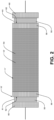
- the TCES device 10 may be supported by and contained within a support frame 70.
- the support frame 70 has a substantially rectangular prism shape.
- the support frame 70 includes bars along each edge and open faces between the bars.
- the support frame 70 defines standard shipping container outer dimensions.
- the support frame 70 may define a length 72 of about 40 feet, a width 74 of about 8 feet, and a height 76 of about 8.5 feet. Accordingly, the TCES device 10 may be readily transported.
- the reactive material 12 of the bed 11 preferably has a high reactive stability (i.e., the ability to reuse the reactive material 12 for thousands of cycles with negligible degradation in performance), high discharge temperature, and high energy density.
- the reactive material 12 is configured to release oxygen upon being heated to a reduction temperature, and generate heat when exposed to oxygen. More particularly, the reactive material 12 is a redox material that undergoes oxidation and reduction reactions to change phase.
- the reactive material 12 consumes heat to undergo reduction and release oxygen.
- the reactive material 12 consumes oxygen to undergo oxidation and generate heat.
- the reactive material 12 advantageously uses oxygen as a gaseous reactant, rather than CO 2 , H 2 , or CO, by way of example.
- the oxygen for the process may come from air.
- the bed 11 of the reactive material 12 can be a packed bed or porous bed.
- the bed 11 is a packed bed including a plurality of granular particles.
- An average particle size ranges from about 100 ⁇ m-8 mm. In one embodiment, particle sizes range from about 125-180 ⁇ m. The average particle size can be optimized to increase energy density.
- the particles define an interparticle pore size between particles.
- the particles preferably also define an intraparticle pore size within the particles, so that the bed 11 has a dual porosity.
- the average interparticle pore size ranges from about 1-8 mm. In some embodiments, the average interparticle pore size is optionally about 1-2 mm, optionally about 2-3 mm, optionally about 3-4 mm, optionally about 4-5 mm, optionally about 5-6 mm, optionally about 6-7 mm, or optionally about 7-8 mm.
- the average intraparticle pore size ranges from about 10-100 ⁇ m.
- the average intraparticle pore size is optionally about 10-20 ⁇ m, optionally about 20-30 ⁇ m, optionally about 30-40 ⁇ m, optionally about 40-50 ⁇ m, optionally about 50-60 ⁇ m, optionally about 60-70 ⁇ m, optionally about 70-80 ⁇ m, optionally about 80-90 ⁇ m, or optionally about 90-100 ⁇ m.
- a total porosity of the bed 11 is less than or equal to about 75%, optionally less than or equal to about 70%, optionally less than or equal to about 65%, optionally less than or equal to about 60%, optionally less than or equal to about 55%, optionally less than or equal to about 50%, optionally less than or equal to about 45%, optionally less than or equal to about 40%, and optionally less than or equal to about 35%.
- the total porosity may be optimized depending on acceptable pressure drop. In one embodiment, pressure drop is about 0.05 bar.
- a volumetric energy density of the bed 11 is at least about 1000 MJm -3 , optionally at least about 1100 MJm -3 , optionally at least about 1200 MJm -3 , optionally at least about 1300 MJm -3 , optionally at least about 1400 MJm -3 , optionally at least about 1500 MJm -3 , optionally at least about 1600 MJm -3 , optionally at least about 1700 MJm -3 , optionally at least about 1800 MJm -3 , optionally at least about 1900 MJm -3 , optionally at least about 2000 MJm -3 , optionally at least about 2100 MJm -3 , optionally at least about 2200 MJm -3 , optionally at least about 2300 MJm -3 , optionally at least about 2400 MJm -3 , optionally at least about 2500 MJm -3 , optionally at least about 2600 MJm -3
- the reactive material 12 may comprise a metal oxide, which may be a metal-metal oxide.
- the reactive material 12 is formed from a transition metal oxide and an alkaline earth metal oxide that acts as a sintering inhibitor.
- the reactive material 12 comprises a magnesium-manganese oxide.
- the reactive material 12 may comprise a perovskite such as doped calcium manganite or lanthanum strontium cobalt ferrite.
- the reactive material 12 may further comprise a dopant to increase energy density, such as cobalt, iron, chromium, molybdenum, vanadium, zinc, cerium, and/or nickel.
- a molar ratio of manganese to magnesium can be adjusted for a specific operating temperature range to obtain high reactive stability. In general, increasing an amount of magnesium decreases slag formation (inhibiting undesirable sintering of the reactive material 12 when heated) and facilitates operation of the TCES device 10 at higher temperatures.
- the molar ratio ranges from about 1:4-4:1, optionally about 1:2-3:1, and optionally about 2:3-2:1.
- the molar ratio is optionally about 2:3, optionally about 1:1, or optionally about 2:1.
- Reactive materials 12 comprising magnesium-manganese oxides have desirably high exergetic efficiencies via high operating temperatures, low cost, fast reaction kinetics, and the use of air as the reacting gas for discharging heat, thereby eliminating the need for gas storage-and-management systems.
- Magnesium-manganese oxides do not require very low partial pressures of oxygen to achieve high energy densities, making use of magnesium-manganese oxides in the TCES device 10 practical for large-scale operation.
- Reactive materials 12 comprising magnesium-manganese oxides have a high degree of reactive stability under high-temperature cycling, such as between 1000°C and 1500°C, and optionally between 1200°C and 1500°C. Furthermore, magnesium-manganese oxide-containing reactive materials 12 undergo phase change reactions at high operating temperatures, such as at least about 1000°C, optionally at least about 1100°C, optionally at least about 1200°C, optionally at least about 1300°C, optionally at least about 1400°C, optionally at least about 1500°C, and preferably at least about 1600°C.
- the magnesium-manganese oxide reactive materials 12 may have volumetric energy densities of at least about 1000 MJm -3 , optionally at least about 1100 MJm -3 , optionally at least about 1200 MJm -3 , optionally at least about 1300 MJm -3 , optionally at least about 1400 MJm -3 , optionally at least about 1500 MJm -3 , optionally at least about 1600 MJm -3 , optionally at least about 1700 MJm -3 , optionally at least about 1800 MJm -3 , optionally at least about 1900 MJm -3 , optionally at least about 2000 MJm -3 , optionally at least about 2100 MJm -3 , optionally at least about 2200 MJm -3 , optionally at least about 2300 MJm -3 , optionally at least about 2400 MJm -3 , optionally at least about 2500 MJm -3 , optionally at least about 2600 MJm -3 , optionally at
- magnesium oxide and manganese oxide react to form magnesium-manganate spinel (both cubic and tetragonal) when heated in air or oxygen.
- the crystal structure of a spinel phase can be viewed as a face-centered cubic (“FCC") lattice of oxygen ions with cations at tetrahedral and octahedral sites.
- MgMn 2 O 4 is a tetragonal spinel at room temperature.
- At high temperatures e.g., at least about 780°C, optionally at least about 800°C, optionally at least about 850°C, optionally at least about 900°C, and optionally at least about 950°C
- the heat of formation of MgMn 2 O 4 from MgO and Mn 2 O 3 using high-temperature solution has been reported to be about -11.4 kJmol -1 .
- An enthalpy of transformation between the cubic spinel and tetragonal spinel is about 20.9 kJmol -1 at 850 °C.
- Magnesium-manganese oxide spinel is of the form (Mg 1-x Mn x ) 3- ⁇ O 4 .
- ⁇ is the cation vacancy concentration in the spinel
- x is the manganese-to-magnesium molar ratio.
- the non-stoichiometric reaction for reduction of a magnesium-manganate spinel is given by 1 3 ⁇ ⁇ 1 Mg 1 ⁇ y Mn y 3 ⁇ ⁇ 1 O 4 ⁇ 1 3 ⁇ ⁇ 2 Mg 1 ⁇ y Mn y 3 ⁇ ⁇ 2 O 4 + 2 ⁇ 2 ⁇ ⁇ 1 3 ⁇ ⁇ 1 3 ⁇ ⁇ 2 O 2
- the cation vacancy concentration in the spinel changes from ⁇ 1 to ⁇ 2 as the spinel loses oxygen.
- a further source of energy storage is the decomposition of the monoxide phase, 2 1 ⁇ ⁇ 1 ⁇ Mg 1 ⁇ y Mn y 1 ⁇ ⁇ 1 ⁇ O ⁇ + ⁇ 1 ⁇ ⁇ ⁇ 2 ⁇ 1 ⁇ ⁇ 1 ⁇ 1 ⁇ ⁇ 2 ⁇ O 2
- the cation vacancy concentration in the spinel phase changes from ⁇ 1 * to ⁇ 2 * as the spinel loses oxygen.
- the amount of chemical energy storage increases with the amount of oxygen released from the non-stoichiometric monoxide.
- the defect reaction involves the reduction of Mn 3+ to Mn 2+ and the formation of charge-compensating cation vacancies according to the reaction, Va " Mn + 2 Mn ⁇ Mn + 3 O x o ⁇ 2 Mn x Mn + 2 O x o + 1 2 O 2 g
- n O 2 is the number of moles of oxygen released at thermodynamic equilibrium when a spinel -monoxide ((Mg 1-y Mny) 1- ⁇ 2 * O and (Mg 1-z Mn z ) 3- ⁇ O 4 ) two-phase solid solution is reduced to mole of (Mg 1-x Mn x ) 1- ⁇ 1 * .
- the overall decomposition simplifies into the reversible reaction given by Mg x Mn O 1 + x + C 1 ⁇ Mg x Mn O 1 + x + C 2 + C 1 ⁇ C 2 2 O 2
- Equation (6) does not provide information about the phases present in the chemical reaction; however, if the value of C1 is known (at a given T and P O2 ), then the enthalpy of MgxMnO 1+x+C1 can be measured using calorimetry.
- a gravimetric energy storage density and maximum achievable storage efficiency of magnesium-manganese oxides with various manganese-to-magnesium molar ratios can be calculated using the CALPHAD model described in Panda SK, Jung IH, "Critical Evaluation and Thermodynamic Modeling of the Mg-Mn-O (MgO-MnO-MnO2) System," Journal of the American Ceramic Society, 2014 Oct 1;97(10):3328-40 .
- the TCES device 10 may be used in an electrical-to-electrical energy storage system 80 and operation.
- the system 80 generally includes the TCES device 10, a blower 82, and a turbo-generator set 84.
- the turbo-generator set 84 includes a compressor 86, a turbine 88, and an electrical generator 90.
- a first valve 92 which is a three-way valve, is fluidly connected to the TCES device 10, the blower 82, and the compressor 86. In a first position, the first valve 92 fluidly connected the TCES device 10 and the blower 82. In a second position, the first valve 92 fluidly connected the TCES device 10 and the compressor 86.
- a first line 94 e.g., pipe
- a second line 96 is disposed between the first valve 92 and the blower 82.
- a third line 98 is disposed between the first valve 92 and the compressor 86.
- a second valve 100 is disposed between the TCES device 10 and the turbine 88.
- a fourth line 102 connects the TCES device 10 and the second valve 100.
- a fifth line 104 connected the second valve 100 and the turbine 88.
- a sixth or bypass line is provided between the third line 98 and the fourth line 102.
- a third valve 108 which is preferably a variable control valve, is provided on the bypass line 106.
- an outlet gas discharged from the compressor 86 is split into a first portion and a second portion. The first portion is provided to the first valve 92.
- the second portion is provided to the bypass line 106.
- the second portion is combined with an outlet gas discharged from the TCES device 10 and provided to the second valve 100. An amount of the second portion is controlled by the third valve 108.
- the system 80 performs an energy storage operation and an energy recovery operation.
- electricity is converted to heat to cause the reactive material 12 in the TCES device 10 to be reduced in an endothermic reaction.
- the reduction reaction generates oxygen, which is removed by the blower 82.
- oxygen is provided to the TCES device 10 by the compressor 86 to react with the reactive material 12 in a highly exothermic manner. Accordingly, gas in the TCES device 10 is heated and discharged to the turbine 88, which is used to power the generator 90.
- the third valve 108 is operated to allow a portion of the oxygen to bypass the TCES device 10 in order to provide a consistent temperature to the turbine 88.
- the system 80 is modular such that it can be integrated with existing power grids and infrastructure. Furthermore, a quantity of TCES devices 10 can be increased to increase energy storage capacity. In one embodiment, 40-50 TCES devices 10 are stacked to achieve a desired storage capacity.
- FIG. 2 depicts the system 80 during the energy storage operation.
- the system 80 stores energy, for example, when the grid produces excess power.
- a first valve 92 is in the first position to fluidly connect the blower 82 and the TCES device 10.
- the blower 82 is an industrial suction blower.
- the second valve 100 is in a closed position.
- the TCES device 10 is fluidly isolated from the compressor 86 and the turbine 88.
- a method of storing energy using the system 80 includes electrically connecting the TCES device 10 to an electricity source 120 to heat the heater 16, thereby heating the reactive material 12 ( Figure 1 ).
- the reactive material 12 is heated to a reduction temperature of at least about 1000°C, optionally at least about 1100°C, optionally at least about 1200°C, optionally at least about 1300°C, optionally at least about 1400°C, optionally at least about 1500°C, and optionally at least about 1600°C.
- the reactive material 12 is chemically reduced to generate oxygen.
- magnesium-manganate oxide spinel is reduced to magnesium oxide and manganese oxide, as described above
- the method further includes removing the evolved oxygen.
- the oxygen is removed by the blower 82.
- the first opening 38 of the TCES device 10 is fluidly connected to a suction side of the blower 82, with the first valve 92 being disposed therebetween.
- the blower 82 is operated at a constant oxygen partial pressure.
- the constant oxygen partial pressure ranges from about 0.01-0.2 atm, and preferably about 0.01-0.1 atm.
- the evolved oxygen may be collected, such as for sale or use in other processes.
- an inert sweep gas may be circulated through the interior volume 36 (not shown). The use of an inert sweep gas may further improve energy density.
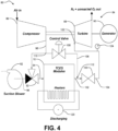
- Figure 3 depicts the system 80 during the energy recovery operation.
- the system 80 releases energy, for example, when energy demand exceeds supply.
- the first valve 92 is in the second position to fluidly connect the compressor 86 and the TCES device 10, while fluidly isolating the TCES device 10 from the blower 82.
- the second valve 100 fluidly connects the turbine 88 and the TCES device 10.
- the turbine 88 expands heated air/oxygen-rich gas that it receives from the TCES device 10 to power the generator 90, which generates electricity.
- a method of releasing energy includes providing oxygen to the interior volume 36 of the TCES device 10.
- the compressor 86 is operated to flow pressurized oxygen into the second opening 40 and across and/or through the reactive material 12 (e.g., through the pores of the reactive material).
- the oxygen comes from pressurized air.
- An oxidation pressure of the inlet air ranges from about 20-25 bar.
- the oxidation pressure ranges from optionally about 20-21 bar, optionally about 21-22 bar, optionally about 22-23 bar, optionally about 23-24 bar, or optionally about 24-25 bar.
- An oxidation temperature of the inlet air ranges from about 200-400°C.
- the oxidation temperature may range from optionally about 200-225°C, optionally about 225-250°C, optionally about 250-275°C, optionally about 275-300°C, optionally about 300-325°C, optionally about 325-350°C, optionally about 350-375°C, or optionally about 375-400°C.
- the oxygen in the air reacts with the reactive material 12 to chemically oxidize the reactive material 12.
- magnesium oxide and manganese oxide react with the oxygen to form magnesium-manganate spinel.
- the reaction is highly exothermic, and therefore heat is released to the oxygen-depleted air. The reaction continues until substantially all of the reactive material 12 is oxidized.
- the amount of heat released to the oxygen-depleted air varies as the oxidation reaction progresses. For example, a first temperature near the beginning of the energy recovery operation may be greater than a second temperature near an end of the energy recovery operation.
- a turbine temperature at the turbine inlet 122 is substantially constant.
- the system 80 further includes a control unit (not shown).
- the third valve 108 allows some of the air leaving the compressor 86 to bypass the TCES device 10 through the bypass line 106.
- the air in the bypass line 106 admixes with heated, oxygen-depleted air discharged from the second opening 40 of the TCES device 10 at the second junction 112.
- An admixture air temperature is controlled to meet inlet specifications of the turbine 88.
- a temperature sensor 124 in the mixture air feeds the control unit, which controls the third valve 108 to moderate the amount of bypass air so that the predetermined turbine inlet temperature is maintained
- the mixed air is received by the turbine 88 at the turbine inlet 122.
- the mixed air expands across the turbine 88 to power the generator 90.
- the generator 90 delivers electricity back to the power grid as needed.
Landscapes
- Engineering & Computer Science (AREA)
- Mechanical Engineering (AREA)
- General Engineering & Computer Science (AREA)
- Physics & Mathematics (AREA)
- Thermal Sciences (AREA)
- Chemical & Material Sciences (AREA)
- Chemical Kinetics & Catalysis (AREA)
- General Chemical & Material Sciences (AREA)
- Combustion & Propulsion (AREA)
- Inorganic Compounds Of Heavy Metals (AREA)
- Compositions Of Oxide Ceramics (AREA)
- Battery Electrode And Active Subsutance (AREA)
Claims (15)
- Thermochemische Energiespeichervorrichtung (10), umfassend:ein Gefäß (14), das ein inneres Volumen definiert, wobei das Gefäß eine erste Öffnung und eine zweite Öffnung beinhaltet;ein poröses Bett (11, 11'), das innerhalb des inneren Volumens angeordnet ist und in flüssiger Kommunikation mit der ersten Öffnung und der zweiten Öffnung ist, das poröse Bett umfassend ein reaktives Material (12, 12'), wobei das reaktive Material konfiguriert ist, um Sauerstoff freizusetzen, wenn es auf eine Reduktionstemperatur erhitzt wird, und Wärme zu erzeugen, wenn es Sauerstoff ausgesetzt wird; undeine Heizung (16, 16'), die konfiguriert ist, um das reaktive Material zu erhitzen, wobei die Heizung in Kontakt mit dem reaktiven Material ist oder ein Heizelement beinhaltet, das in das reaktive Material (12) eingebettet ist, dadurch gekennzeichnet, dass die Heizung eines oder beide von Folgenden beinhaltet(A) ein in das reaktive Material eingebettetes Heizelement (16), dessen Enden elektrisch mit einer Stromquelle verbunden sind, und/oder(B) ein erstes Paar keramischer Elektroden (56, 58), wozwischen das poröse Bett angeordnet ist, und ein zweites Paar keramischer Elektroden, das das erste Paar keramischer Elektroden und das dazwischen angeordnete poröse Bett aufweist.
- Vorrichtung nach Anspruch 1, wobei:das Gefäß (14) einen Mantel (30), eine erste Endkappe (32) und eine zweite Endkappe (34) beinhaltet, wobei der Mantel (30) und die erste und die zweite Endkappe (32, 34) zusammenwirken, um zumindest teilweise ein inneres Volumen (36) zu definieren, das einen Durchmesser aufweist;das Heizelement mindestens etwa 75 % des Durchmessers des inneren Volumens (36) überspannt;das Heizelement eine Serpentinen- oder Spulenform umfasst; unddas reaktive Material ein Metalloxid umfasst.
- Vorrichtung nach Anspruch 2, wobei das Metalloxid ein Magnesium-Mangan-Oxid umfasst.
- Vorrichtung nach Anspruch 1, wobei:das reaktive Material elektrisch leitfähig ist; unddas poröse Bett eine Vielzahl von Partikeln umfasst, umfassend das reaktive Material, wobei die Vielzahl von Partikeln eine durchschnittliche Größe in einem Bereich von etwa 100 µm bis 8 mm definiert.
- Vorrichtung nach Anspruch 1, wobei das poröse Bett eine Gesamtporosität von weniger als oder gleich wie etwa 70% umfasst.
- Vorrichtung nach Anspruch 1, wobei die Vorrichtung, wenn sie die Merkmale von Option A umfasst, ferner Folgendes umfasst:Isolierung (64, 66), die zwischen dem porösen Bett und einem Mantel des Gefäßes angeordnet ist, wobei die Isolierung in thermischer Verbindung mit dem porösen Bett ist;
undwobei die Heizung mindestens 1600 °C widersteht. - Vorrichtung nach Anspruch 6, wobei die Isolierung eine erste Isolierschicht und eine zweite Isolierschicht umfasst, wobei die erste Isolierschicht zwischen dem Mantel und der zweiten Isolierschicht angeordnet ist und die zweite Isolierschicht zwischen der ersten Isolierschicht und dem porösen Bett angeordnet ist.
- Vorrichtung nach Anspruch 7, wobei die erste Isolierschicht eine Vielzahl von feuerfesten Steinen umfasst, die feuerfesten Steine umfassend Aluminium, Calciumaluminat, Zirkoniumoxid, Magnesiumaluminat, eine Unterkombination davon oder eine Kombination davon.
- Vorrichtung nach Anspruch 7, wobei die zweite Isolierschicht mikroporöses Aluminiumoxid, mikroporöses Siliciumdioxid, Aluminiumoxid, faserförmiges Zirkoniumdioxid, mikroporöses Zirkoniumdioxid, eine Unterkombination davon oder eine Kombination davon umfasst.
- Vorrichtung nach Anspruch 1, ferner umfassend ein Kühlsystem (20) in thermischer Verbindung mit dem porösen Bett umfasst, wobei das Kühlsystem konfiguriert ist, um ein Wärmeübertragungsfluid zwischen dem porösen Bett und einem Mantel des Gefäßes zirkulieren zu lassen.
- Vorrichtung nach Anspruch 1, wobei:
wenn umfassend die Merkmale von Option B,
die Heizung zum Widerstandserhitzen des porösen Betts konfiguriert ist. - Vorrichtung nach Anspruch 1 oder 11, wobei:wenn umfassend die Merkmale von Option B,das erste Paar keramischer Elektroden ein erstes keramisches Material umfasst, das die chemische Formel La1-xAxCrO3 aufweist, wobei A ausgewählt ist aus der Gruppe, bestehend aus Mg, Ca, Sr, Ba oder Kombinationen davon, und x in einem Bereich von 0-0,1 ist; unddas zweite Paar keramischer Elektroden ein zweites keramisches Material umfasst, das die chemische Formel B1-yCyDO3 aufweist, wobei B ausgewählt ist aus der Gruppe, bestehend aus La, Ce, Pr, Nd, Pm, Sm, Eu, Gd, Tb, Dy, Ho, Er, Tm, Yb, Lu, Al, Sc, Ti, Y, Zr, Hf oder Kombinationen davon; C ausgewählt ist aus der Gruppe, bestehend aus Sr, Ba oder einer Kombination davon; D ausgewählt ist aus der Gruppe, bestehend aus Co, Mn, Ni, Fe oder Kombinationen davon; und y in einem Bereich von etwa 0,3-0,6 ist.
- Vorrichtung nach Anspruch 12, wobei das erste keramische Material LaCrO3 umfasst und das zweite keramische Material La0,7Sr0,3CoO3 umfasst.
- Verfahren zum Speichern von Strom und zum Rückgewinnen von Strom, wobei das Verfahren Folgendes umfasst:Speichern von Strom durch:(a) Bereitstellen von Strom für eine Heizung (16, 16'), wobei die Heizung konfiguriert ist, um ein reaktives Material (12, 12') zu erhitzen, das in einem Gefäß (14) angeordnet ist, wobei die Heizung in thermischem Kontakt mit dem reaktiven Material ist oder ein Heizelement beinhaltet, das in das reaktive Material (12) eingebettet ist, wobei das Gefäß einen Mantel (30), eine erste Endkappe (32) und eine zweite Endkappe (34) beinhaltet, wobei der Mantel (30) und die erste und die zweite Endkappe (32, 34) zusammenwirken, um zumindest teilweise ein inneres Volumen (36) zu definieren, das einen Durchmesser aufweist, das Heizelement mindestens etwa 75 % des Durchmessers des inneren Volumens (36) überspannt, und das reaktive Material konfiguriert ist, um Sauerstoff freizusetzen; und(b) Entnehmen mindestens eines Teils des Sauerstoffs aus dem Gefäß;undRückgewinnen von Strom durch:(c) Bereitstellen von Sauerstoff in das Gefäß, wobei der Sauerstoff chemisch mit dem reaktiven Material reagiert, um ein erhitztes, sauerstoffarmes Fluid zu erzeugen;(d) Entnehmen des erhitzten, sauerstoffarmen Gases aus dem Gefäß;(e) Bereitstellen des erhitzten, sauerstoffarmen Gases zu einer Turbine (88); und(f) Antreiben eines Generators (90) mit der Turbine, um Strom zu erzeugen.
- Verfahren nach Anspruch 14, wobei (c) das Bereitstellen von Sauerstoff ein Bereitstellen von Luft für das Gefäß umfasst, wobei das Bereitstellen von Luft ein Bereitstellen von Luft bei einem Druck in einem Bereich von etwa 20-25 bar und einer Temperatur in einem Bereich von etwa 200-400 °C umfasst, und leitet Strom durch das reaktive Material.
Applications Claiming Priority (2)
| Application Number | Priority Date | Filing Date | Title |
|---|---|---|---|
| US201962789169P | 2019-01-07 | 2019-01-07 | |
| PCT/US2020/012551 WO2020146361A1 (en) | 2019-01-07 | 2020-01-07 | System and operation for thermochemical renewable energy storage |
Publications (4)
| Publication Number | Publication Date |
|---|---|
| EP3909088A1 EP3909088A1 (de) | 2021-11-17 |
| EP3909088A4 EP3909088A4 (de) | 2022-10-19 |
| EP3909088B1 true EP3909088B1 (de) | 2025-03-26 |
| EP3909088C0 EP3909088C0 (de) | 2025-03-26 |
Family
ID=71521922
Family Applications (1)
| Application Number | Title | Priority Date | Filing Date |
|---|---|---|---|
| EP20738693.9A Active EP3909088B1 (de) | 2019-01-07 | 2020-01-07 | System und betrieb zur speicherung von thermochemischer erneuerbarer energie |
Country Status (5)
| Country | Link |
|---|---|
| US (2) | US11754346B2 (de) |
| EP (1) | EP3909088B1 (de) |
| CN (1) | CN113557617B (de) |
| ES (1) | ES3021608T3 (de) |
| WO (1) | WO2020146361A1 (de) |
Families Citing this family (13)
| Publication number | Priority date | Publication date | Assignee | Title |
|---|---|---|---|---|
| ES3021608T3 (en) | 2019-01-07 | 2025-05-27 | Univ Michigan State | System and operation for thermochemical renewable energy storage |
| US12313352B2 (en) | 2019-07-09 | 2025-05-27 | Board Of Trustees Of Michigan State University | Heat exchanger and method of making same |
| EP3882554A1 (de) * | 2020-03-19 | 2021-09-22 | Nederlandse Organisatie voor toegepast- natuurwetenschappelijk Onderzoek TNO | Interne konfiguration für redox-basierte wärmespeichersysteme |
| US11959011B2 (en) * | 2020-08-07 | 2024-04-16 | Arizona Board Of Regents On Behalf Of Arizona State University | High-temperature thermochemical energy storage materials using doped magnesium-transition metal spinel oxides |
| EP4196672A4 (de) * | 2020-08-11 | 2023-11-22 | Board Of Trustees Of Michigan State University | Vorrichtung für festen thermochemischen brennstoff |
| CN113251679B (zh) * | 2021-05-19 | 2022-03-11 | 华中科技大学 | 一种基于四氧化三钴储热介质面向太阳能的储能反应器 |
| US11698232B1 (en) | 2022-02-15 | 2023-07-11 | Siemens Energy, Inc. | System and method utilizing thermochemical energy storage for abatement of volatile organic compounds |
| CN114704380B (zh) * | 2022-03-14 | 2023-07-14 | 国网浙江省电力有限公司电力科学研究院 | 耦合热化学储能的燃煤机组调峰发电系统及方法 |
| JP2025519035A (ja) * | 2022-05-11 | 2025-06-24 | ボード オブ トラスティーズ オブ ミシガン ステート ユニバーシティ | 固体太陽熱化学燃料用酸化反応器 |
| WO2024064648A1 (en) * | 2022-09-19 | 2024-03-28 | Flying Diamonds Energy Company, Llc | Thermal storage unit |
| WO2025040254A1 (de) | 2023-08-23 | 2025-02-27 | Heionit Gmbh | Energiewandlermaterial und galvanische zelle |
| DE102024101074A1 (de) | 2024-01-15 | 2025-07-17 | Deutsches Zentrum für Luft- und Raumfahrt e.V. | Verwendung eines dotierten Metalloxids in thermochemischen Kreisprozessen |
| US20250347473A1 (en) * | 2024-05-10 | 2025-11-13 | RedoxBlox, Inc. | Energy storage articles and methods for making and using the same |
Family Cites Families (13)
| Publication number | Priority date | Publication date | Assignee | Title |
|---|---|---|---|---|
| EP1213052A1 (de) * | 2000-12-09 | 2002-06-12 | Degussa AG | Elektrisch beheizter Festbettreaktor und seine Verwendung |
| US6893762B2 (en) * | 2002-01-16 | 2005-05-17 | Alberta Research Council, Inc. | Metal-supported tubular micro-fuel cell |
| EP2101051A1 (de) | 2008-03-12 | 2009-09-16 | Siemens Aktiengesellschaft | Speicherung elektrischer Energie mit Wärmespeicher und Rückverstromung mittels eines thermodynamischen Kreisprozesses |
| KR20170123711A (ko) * | 2009-08-07 | 2017-11-08 | 브릴리언트 라이트 파워, 인크. | 불균일 수소-촉매 파워 시스템 |
| EP2729242A4 (de) | 2011-07-08 | 2015-03-04 | Univ Florida | Poröse stabilisierte ablagen, verfahren zu ihrer herstellung und artikel damit |
| JP2015518498A (ja) * | 2012-03-20 | 2015-07-02 | エクソンモービル ケミカル パテンツ インコーポレイテッド | 熱分解反応器用の断熱部品 |
| WO2014062464A1 (en) | 2012-10-16 | 2014-04-24 | Abengoa Solar Inc | Coupled chemical-thermal solar power system and method |
| US9702348B2 (en) * | 2013-04-03 | 2017-07-11 | Alliance For Sustainable Energy, Llc | Chemical looping fluidized-bed concentrating solar power system and method |
| US10107268B1 (en) * | 2014-09-05 | 2018-10-23 | National Technology & Engineering Solutions Of Sandia, Llc | Thermal energy storage and power generation systems and methods |
| US10578341B2 (en) | 2014-12-12 | 2020-03-03 | Zhejiang University | Dual-cavity method and device for collecting and storing solar energy with metal oxide particles |
| US10082045B2 (en) * | 2016-12-28 | 2018-09-25 | X Development Llc | Use of regenerator in thermodynamic cycle system |
| ES3021608T3 (en) | 2019-01-07 | 2025-05-27 | Univ Michigan State | System and operation for thermochemical renewable energy storage |
| CN116678246A (zh) * | 2023-06-08 | 2023-09-01 | 国网浙江省电力有限公司电力科学研究院 | 一种多元储热系统及阵列式蓄放热方法 |
-
2020
- 2020-01-07 ES ES20738693T patent/ES3021608T3/es active Active
- 2020-01-07 CN CN202080019432.0A patent/CN113557617B/zh active Active
- 2020-01-07 EP EP20738693.9A patent/EP3909088B1/de active Active
- 2020-01-07 WO PCT/US2020/012551 patent/WO2020146361A1/en not_active Ceased
-
2021
- 2021-06-30 US US17/363,541 patent/US11754346B2/en active Active
-
2023
- 2023-08-28 US US18/238,579 patent/US12123655B2/en active Active
Also Published As
| Publication number | Publication date |
|---|---|
| EP3909088A1 (de) | 2021-11-17 |
| US11754346B2 (en) | 2023-09-12 |
| US20210325124A1 (en) | 2021-10-21 |
| ES3021608T3 (en) | 2025-05-27 |
| CN113557617B (zh) | 2024-10-29 |
| US20230408209A1 (en) | 2023-12-21 |
| CN113557617A (zh) | 2021-10-26 |
| EP3909088C0 (de) | 2025-03-26 |
| US12123655B2 (en) | 2024-10-22 |
| WO2020146361A1 (en) | 2020-07-16 |
| EP3909088A4 (de) | 2022-10-19 |
Similar Documents
| Publication | Publication Date | Title |
|---|---|---|
| EP3909088B1 (de) | System und betrieb zur speicherung von thermochemischer erneuerbarer energie | |
| Song et al. | High‐temperature CO2 electrolysis in solid oxide electrolysis cells: developments, challenges, and prospects | |
| Ji et al. | Electrochemical performance of La-doped Sr2MgMoO6− δ in natural gas | |
| Ding et al. | Enhanced oxygen reduction activity on surface-decorated perovskite La0. 6Ni0. 4FeO3 cathode for solid oxide fuel cells | |
| Mori et al. | Control of the thermal expansion of strontium‐doped lanthanum chromite perovskites by B‐site doping for high‐temperature solid oxide fuel cell separators | |
| JP6691247B1 (ja) | 反応装置及び燃料電池発電システム | |
| US12359327B2 (en) | Electrochemical cells for hydrogen gas production and electricity generation, and related systems and methods | |
| US20230193486A1 (en) | Systems and methods for generating synthesis gas for ammonia production | |
| JP2009035447A (ja) | セラミックス粉体及びその焼結体とそれを利用した固体酸化物型燃料電池用空気極 | |
| JP2009037872A (ja) | セラミックス粉体と該粉体を用いた中温作動固体酸化物型燃料電池の空気極と電解質層との積層部材並びにその製造方法 | |
| Ni et al. | Investigation of La1− xSmx− ySryCoO3− δ cathode for intermediate temperature solid oxide fuel cells | |
| Yang et al. | Self-assembled La0. 6Sr0. 4FeO3-δ-La1. 2Sr0. 8NiO4+ δ composite cathode for protonic ceramic fuel cells | |
| JP2009037874A (ja) | 中温作動固体酸化物形燃料電池の空気極支持形単セルの製造方法 | |
| Yang et al. | Cobalt-free perovskite Ba0. 95La0. 05FeO3-δ as efficient and durable oxygen electrode for solid oxide electrolysis cells | |
| Ding et al. | Enhanced SOFC cathode performance by infiltrating Ba0. 5Sr0. 5Co0. 8Fe0. 2O3− δ nanoparticles for intermediate temperature solid oxide fuel cells | |
| Wei et al. | A-Site Nonstoichiometric Ba x Co0. 4Fe0. 4Zr0. 1Y0. 1O3− δ Cathode for Protonic Ceramics Fuel Cells | |
| Li | Solid oxide fuel cells | |
| CN116096497A (zh) | 包含具有洗脱出的过渡元素的钙钛矿结构材料的干式重整催化剂及其制备方法以及包含其的干式重整催化剂系统和固体氧化物燃料电池 | |
| CN104396056B (zh) | 电蓄能电池的存储结构 | |
| JP2020077567A (ja) | 反応装置、及び燃料電池発電システム | |
| ZHANG et al. | Performance of reversible solid oxide cells based on La0. 6Ca0. 4Fe0. 7Sc0. 1Ni0. 2O3–δ oxygen electrode | |
| Irvine et al. | Hydrogen ionic conductors and ammonia conversions | |
| CN115868047B (zh) | 运行sofc以联合生产电和一氧化氮的方法 | |
| Jagielski et al. | Electrochemical performance of solid oxide cells with Co-free Sr0. 7Ce0. 3MnO3-δ-based oxygen electrodes | |
| Liu et al. | Status and prospects of electrode materials for symmetrical solid oxide fuel cells: A concise review |
Legal Events
| Date | Code | Title | Description |
|---|---|---|---|
| STAA | Information on the status of an ep patent application or granted ep patent |
Free format text: STATUS: THE INTERNATIONAL PUBLICATION HAS BEEN MADE |
|
| PUAI | Public reference made under article 153(3) epc to a published international application that has entered the european phase |
Free format text: ORIGINAL CODE: 0009012 |
|
| STAA | Information on the status of an ep patent application or granted ep patent |
Free format text: STATUS: REQUEST FOR EXAMINATION WAS MADE |
|
| 17P | Request for examination filed |
Effective date: 20210707 |
|
| AK | Designated contracting states |
Kind code of ref document: A1 Designated state(s): AL AT BE BG CH CY CZ DE DK EE ES FI FR GB GR HR HU IE IS IT LI LT LU LV MC MK MT NL NO PL PT RO RS SE SI SK SM TR |
|
| DAV | Request for validation of the european patent (deleted) | ||
| DAX | Request for extension of the european patent (deleted) | ||
| A4 | Supplementary search report drawn up and despatched |
Effective date: 20220915 |
|
| RIC1 | Information provided on ipc code assigned before grant |
Ipc: F28D 7/02 20060101ALI20220909BHEP Ipc: F01K 3/18 20060101ALI20220909BHEP Ipc: H01M 4/36 20060101ALI20220909BHEP Ipc: F28D 20/00 20060101ALI20220909BHEP Ipc: H01M 4/86 20060101AFI20220909BHEP |
|
| STAA | Information on the status of an ep patent application or granted ep patent |
Free format text: STATUS: EXAMINATION IS IN PROGRESS |
|
| 17Q | First examination report despatched |
Effective date: 20231220 |
|
| GRAP | Despatch of communication of intention to grant a patent |
Free format text: ORIGINAL CODE: EPIDOSNIGR1 |
|
| STAA | Information on the status of an ep patent application or granted ep patent |
Free format text: STATUS: GRANT OF PATENT IS INTENDED |
|
| INTG | Intention to grant announced |
Effective date: 20241014 |
|
| GRAS | Grant fee paid |
Free format text: ORIGINAL CODE: EPIDOSNIGR3 |
|
| GRAA | (expected) grant |
Free format text: ORIGINAL CODE: 0009210 |
|
| STAA | Information on the status of an ep patent application or granted ep patent |
Free format text: STATUS: THE PATENT HAS BEEN GRANTED |
|
| AK | Designated contracting states |
Kind code of ref document: B1 Designated state(s): AL AT BE BG CH CY CZ DE DK EE ES FI FR GB GR HR HU IE IS IT LI LT LU LV MC MK MT NL NO PL PT RO RS SE SI SK SM TR |
|
| REG | Reference to a national code |
Ref country code: GB Ref legal event code: FG4D |
|
| REG | Reference to a national code |
Ref country code: CH Ref legal event code: EP |
|
| REG | Reference to a national code |
Ref country code: DE Ref legal event code: R096 Ref document number: 602020048318 Country of ref document: DE |
|
| REG | Reference to a national code |
Ref country code: IE Ref legal event code: FG4D |
|
| U01 | Request for unitary effect filed |
Effective date: 20250409 |
|
| U07 | Unitary effect registered |
Designated state(s): AT BE BG DE DK EE FI FR IT LT LU LV MT NL PT RO SE SI Effective date: 20250416 |
|
| REG | Reference to a national code |
Ref country code: ES Ref legal event code: FG2A Ref document number: 3021608 Country of ref document: ES Kind code of ref document: T3 Effective date: 20250527 |
|
| PG25 | Lapsed in a contracting state [announced via postgrant information from national office to epo] |
Ref country code: RS Free format text: LAPSE BECAUSE OF FAILURE TO SUBMIT A TRANSLATION OF THE DESCRIPTION OR TO PAY THE FEE WITHIN THE PRESCRIBED TIME-LIMIT Effective date: 20250626 |
|
| PG25 | Lapsed in a contracting state [announced via postgrant information from national office to epo] |
Ref country code: NO Free format text: LAPSE BECAUSE OF FAILURE TO SUBMIT A TRANSLATION OF THE DESCRIPTION OR TO PAY THE FEE WITHIN THE PRESCRIBED TIME-LIMIT Effective date: 20250626 |
|
| PG25 | Lapsed in a contracting state [announced via postgrant information from national office to epo] |
Ref country code: HR Free format text: LAPSE BECAUSE OF FAILURE TO SUBMIT A TRANSLATION OF THE DESCRIPTION OR TO PAY THE FEE WITHIN THE PRESCRIBED TIME-LIMIT Effective date: 20250326 |
|
| PG25 | Lapsed in a contracting state [announced via postgrant information from national office to epo] |
Ref country code: GR Free format text: LAPSE BECAUSE OF FAILURE TO SUBMIT A TRANSLATION OF THE DESCRIPTION OR TO PAY THE FEE WITHIN THE PRESCRIBED TIME-LIMIT Effective date: 20250627 |
|
| PG25 | Lapsed in a contracting state [announced via postgrant information from national office to epo] |
Ref country code: SM Free format text: LAPSE BECAUSE OF FAILURE TO SUBMIT A TRANSLATION OF THE DESCRIPTION OR TO PAY THE FEE WITHIN THE PRESCRIBED TIME-LIMIT Effective date: 20250326 |
|
| PG25 | Lapsed in a contracting state [announced via postgrant information from national office to epo] |
Ref country code: PL Free format text: LAPSE BECAUSE OF FAILURE TO SUBMIT A TRANSLATION OF THE DESCRIPTION OR TO PAY THE FEE WITHIN THE PRESCRIBED TIME-LIMIT Effective date: 20250326 |
|
| PG25 | Lapsed in a contracting state [announced via postgrant information from national office to epo] |
Ref country code: SK Free format text: LAPSE BECAUSE OF FAILURE TO SUBMIT A TRANSLATION OF THE DESCRIPTION OR TO PAY THE FEE WITHIN THE PRESCRIBED TIME-LIMIT Effective date: 20250326 |
|
| PG25 | Lapsed in a contracting state [announced via postgrant information from national office to epo] |
Ref country code: IS Free format text: LAPSE BECAUSE OF FAILURE TO SUBMIT A TRANSLATION OF THE DESCRIPTION OR TO PAY THE FEE WITHIN THE PRESCRIBED TIME-LIMIT Effective date: 20250726 |
|
| PG25 | Lapsed in a contracting state [announced via postgrant information from national office to epo] |
Ref country code: CZ Free format text: LAPSE BECAUSE OF FAILURE TO SUBMIT A TRANSLATION OF THE DESCRIPTION OR TO PAY THE FEE WITHIN THE PRESCRIBED TIME-LIMIT Effective date: 20250326 |
|
| PLBE | No opposition filed within time limit |
Free format text: ORIGINAL CODE: 0009261 |
|
| STAA | Information on the status of an ep patent application or granted ep patent |
Free format text: STATUS: NO OPPOSITION FILED WITHIN TIME LIMIT |
|
| REG | Reference to a national code |
Ref country code: CH Ref legal event code: L10 Free format text: ST27 STATUS EVENT CODE: U-0-0-L10-L00 (AS PROVIDED BY THE NATIONAL OFFICE) Effective date: 20260211 |