EP2249588A2 - Verfahren zur Herstellung eines Faceplates - Google Patents
Verfahren zur Herstellung eines Faceplates Download PDFInfo
- Publication number
- EP2249588A2 EP2249588A2 EP10008436A EP10008436A EP2249588A2 EP 2249588 A2 EP2249588 A2 EP 2249588A2 EP 10008436 A EP10008436 A EP 10008436A EP 10008436 A EP10008436 A EP 10008436A EP 2249588 A2 EP2249588 A2 EP 2249588A2
- Authority
- EP
- European Patent Office
- Prior art keywords
- faceplate
- component
- opening
- hearing aid
- components
- Prior art date
- Legal status (The legal status is an assumption and is not a legal conclusion. Google has not performed a legal analysis and makes no representation as to the accuracy of the status listed.)
- Withdrawn
Links
Images

Classifications
-
- H—ELECTRICITY
- H04—ELECTRIC COMMUNICATION TECHNIQUE
- H04R—LOUDSPEAKERS, MICROPHONES, GRAMOPHONE PICK-UPS OR LIKE ACOUSTIC ELECTROMECHANICAL TRANSDUCERS; ELECTRIC HEARING AIDS; PUBLIC ADDRESS SYSTEMS
- H04R25/00—Electric hearing aids
- H04R25/65—Housing parts, e.g. shells, tips or moulds, or their manufacture
- H04R25/658—Manufacture of housing parts
-
- B—PERFORMING OPERATIONS; TRANSPORTING
- B33—ADDITIVE MANUFACTURING TECHNOLOGY
- B33Y—ADDITIVE MANUFACTURING, i.e. MANUFACTURING OF THREE-DIMENSIONAL [3D] OBJECTS BY ADDITIVE DEPOSITION, ADDITIVE AGGLOMERATION OR ADDITIVE LAYERING, e.g. BY 3D PRINTING, STEREOLITHOGRAPHY OR SELECTIVE LASER SINTERING
- B33Y80/00—Products made by additive manufacturing
-
- H—ELECTRICITY
- H04—ELECTRIC COMMUNICATION TECHNIQUE
- H04R—LOUDSPEAKERS, MICROPHONES, GRAMOPHONE PICK-UPS OR LIKE ACOUSTIC ELECTROMECHANICAL TRANSDUCERS; ELECTRIC HEARING AIDS; PUBLIC ADDRESS SYSTEMS
- H04R2225/00—Details of deaf aids covered by H04R25/00, not provided for in any of its subgroups
- H04R2225/61—Aspects relating to mechanical or electronic switches or control elements, e.g. functioning
-
- H—ELECTRICITY
- H04—ELECTRIC COMMUNICATION TECHNIQUE
- H04R—LOUDSPEAKERS, MICROPHONES, GRAMOPHONE PICK-UPS OR LIKE ACOUSTIC ELECTROMECHANICAL TRANSDUCERS; ELECTRIC HEARING AIDS; PUBLIC ADDRESS SYSTEMS
- H04R2225/00—Details of deaf aids covered by H04R25/00, not provided for in any of its subgroups
- H04R2225/77—Design aspects, e.g. CAD, of hearing aid tips, moulds or housings
-
- H—ELECTRICITY
- H04—ELECTRIC COMMUNICATION TECHNIQUE
- H04R—LOUDSPEAKERS, MICROPHONES, GRAMOPHONE PICK-UPS OR LIKE ACOUSTIC ELECTROMECHANICAL TRANSDUCERS; ELECTRIC HEARING AIDS; PUBLIC ADDRESS SYSTEMS
- H04R25/00—Electric hearing aids
- H04R25/60—Mounting or interconnection of hearing aid parts, e.g. inside tips, housings or to ossicles
- H04R25/603—Mounting or interconnection of hearing aid parts, e.g. inside tips, housings or to ossicles of mechanical or electronic switches or control elements
-
- Y—GENERAL TAGGING OF NEW TECHNOLOGICAL DEVELOPMENTS; GENERAL TAGGING OF CROSS-SECTIONAL TECHNOLOGIES SPANNING OVER SEVERAL SECTIONS OF THE IPC; TECHNICAL SUBJECTS COVERED BY FORMER USPC CROSS-REFERENCE ART COLLECTIONS [XRACs] AND DIGESTS
- Y10—TECHNICAL SUBJECTS COVERED BY FORMER USPC
- Y10T—TECHNICAL SUBJECTS COVERED BY FORMER US CLASSIFICATION
- Y10T29/00—Metal working
- Y10T29/49—Method of mechanical manufacture
- Y10T29/4957—Sound device making
-
- Y—GENERAL TAGGING OF NEW TECHNOLOGICAL DEVELOPMENTS; GENERAL TAGGING OF CROSS-SECTIONAL TECHNOLOGIES SPANNING OVER SEVERAL SECTIONS OF THE IPC; TECHNICAL SUBJECTS COVERED BY FORMER USPC CROSS-REFERENCE ART COLLECTIONS [XRACs] AND DIGESTS
- Y10—TECHNICAL SUBJECTS COVERED BY FORMER USPC
- Y10T—TECHNICAL SUBJECTS COVERED BY FORMER US CLASSIFICATION
- Y10T29/00—Metal working
- Y10T29/49—Method of mechanical manufacture
- Y10T29/4957—Sound device making
- Y10T29/49572—Hearing aid component making
Definitions
- the invention relates to a specified in claim 1 method for producing a faceplate with openings for the installation of components.
- components such as a microphone, amplifier or speakers are integrated in a housing shell which is shaped in accordance with the auditory canal of the hearing device wearer.
- the housing shell is closed at the front with a faceplate. Due to the hearing aid carrier-specifically shaped housing shell and faceplate, the size and shape of the faceplate is variable.
- the faceplate incorporates operating components such as program switches and volume controls.
- the operating components must be accessible from the outside for a hearing aid wearer, as well as have to connect inwardly to the components of the housing shell.
- the patent DE 41 21 311 C1 specifies a hearing aid worn in the ear and a method of making it.
- a housing is closed by a faceplate having a mounting hole penetrating it.
- the operating components are installed in the faceplate in such a way that, after installation, a minimum material thickness of the faceplate remains below the contact surface of the operating component as a counterpressure support. Therefore, the operating components can only be installed in certain areas of the faceplate.
- a control component with a larger diameter but less installation depth to be selected is selected. However, this occupies a larger area of the faceplate. This may require the faceplate to be made larger.
- the patent US Pat. No. 6,870,697 B2 indicates the production of a hearing aid housing, consisting of a faceplate and a housing shell, which are individually adapted to the shape of the ear canal of a user.
- the manufacturing method includes at least one automatic step based on a CAD / CAM model of a hearing aid housing.
- the publication EP 1 641 316 A2 discloses a fastening device for receiving actuating elements with a base plate of a hearing aid.
- the fasteners are installed in drilled holes.
- the object of the invention is achieved by the manufacturing method of independent claim 1.
- the invention claims a method for producing a faceplate of a hearing aid housing with at least one component which can be installed in an opening of the faceplate with the following steps: construction of the faceplate from a first construction material, determination of the size and position of the component in such a way that when the component is installed a predeterminable one Distance between support surface of the component in the opening and the surface facing away from the outside of the faceplate surface is not undershot selection of the corresponding component, drilling one of the selected component corresponding opening in the faceplate in the determined position and installation of the component in the opening.
- the structure of the faceplate comprises an injection molding process.
- FIG. 1 shows a hearing aid housing 2 of an in-the-ear hearing aid in section, which is inserted in the external auditory canal of the ear 13 of a hearing aid wearer.
- the hearing aid housing 2 comprises a housing shell 8 and a faceplate 1 connected thereto, which is arranged to open the auricle of the ear 13.
- a hearing aid electronics not shown, is integrated.
- Housing shell 8 and faceplate 1 consist for example of plastic and are glued together.
- the faceplate 1 are in the FIGS. 2 and 3 integrated components 3 integrated. These components 3 are usually electrical or electronic components, such as volume control or program switch, for operating the hearing aid.
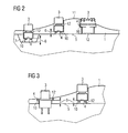
- FIG. 2 is a section of a cross section through a faceplate 1 according to the invention.
- the faceplate 1 is made of a first material, for example by means of stereo lithography process.
- the openings 12 for the components 3, for example volume control or program switch, are already provided in the material structure.
- the openings 12 have projections 10 on which the components 3 come to rest with their bearing surfaces 4. So that the faceplate 1 provides sufficient mechanical resistance during actuation, for example pressing, of the components 3, the distance 6 between the bearing surface 4 or projection 10 and the surface 5 opposite the outer face 11 of the faceplate 1 must not fall below a minimum value. Otherwise, the components 3 could be pressed through the faceplate 1 into the interior of the hearing aid housing.
- a typical value for the minimum distance is, for example, 0.3 mm. The size of the value depends on the first material used.
- the application of the second material 7 is preferably carried out in the same process as the structure of the faceplate. 1
- the position and layer thickness of the second material 7 to be applied must be determined even before the construction of the faceplate 1 begins. This is done, for example, by a computer-controlled calculation method.
- FIG. 3 shows a section of a sectional image through a faceplate 1 which was prepared for example in an injection molding process.
- a minimum distance 6 between the surface 5 and support surface 4 may not be less than in order not to jeopardize the mechanical stability of the faceplate 1.
- the components 3 lie with their bearing surfaces 4 on projections 10 in the openings 12th
- the openings 12 are drilled after the structure of the faceplate 1 has been completed.
- another position on the faceplate must be found, or another component 3, which has a smaller installation depth but a larger diameter, must be selected.
- this method is carried out according to the invention by an automatic process.
- a computer program runs on an automation system which, for example, is connected to a drilling device for drilling the openings 12.
- the automation system dictates the diameter and location of the apertures 12 of the drilling apparatus.
- the different steps of the manufacturing processes can be implemented in a computer program product and executed on an automation system.
Landscapes
- Engineering & Computer Science (AREA)
- Manufacturing & Machinery (AREA)
- Physics & Mathematics (AREA)
- General Health & Medical Sciences (AREA)
- Neurosurgery (AREA)
- Otolaryngology (AREA)
- Health & Medical Sciences (AREA)
- Acoustics & Sound (AREA)
- Signal Processing (AREA)
- Chemical & Material Sciences (AREA)
- Materials Engineering (AREA)
- Injection Moulding Of Plastics Or The Like (AREA)
- Instructional Devices (AREA)
- Management, Administration, Business Operations System, And Electronic Commerce (AREA)
- Switch Cases, Indication, And Locking (AREA)
Abstract
Description
- Die Erfindung betrifft ein im Patentanspruch 1 angegebenes Verfahren zur Herstellung eines Faceplates mit Öffnungen zum Einbau von Komponenten.
- Bei In-dem-Ohr Hörgeräten werden Bauelemente, wie zum Beispiel Mikrofon, Verstärker oder Lautsprecher, in einer Gehäuseschale integriert, die entsprechend dem Gehörgang des Hörgeräteträgers geformt ist. Die Gehäuseschale ist frontseitig mit einem Faceplate abgeschlossen. Aufgrund der Hörgeräteträger-spezifisch geformten Gehäuseschale und Faceplate, ist die Größe und Form der Faceplate variabel.
- In der Faceplate sind Bedienkomponenten, wie Programmschalter und Lautstärkeregler integriert. Die Bedienkomponenten müssen sowohl von außen für einen Hörgeräteträger zugänglich sein, als auch nach innen zu den Bauelementen der Gehäuseschale Verbindung haben.
- Die Patentschrift
DE 41 21 311 C1 gibt ein im Ohr tragbares Hörgerät und ein Verfahren zu dessen Herstellung an. Ein Gehäuse wird von einem Faceplate, das eine sie durchdringende Montageöffnung aufweist, verschlossen. - Für einen sicheren Sitz werden die Bedienkomponenten derart in das Faceplate eingebaut, dass nach Einbau eine minimale Materialdicke des Faceplates unterhalb der Auflagefläche der Bedienkomponente als Gegendruckstütze vorhanden bleibt. Daher können die Bedienkomponenten nur in bestimmten Bereichen des Faceplates eingebaut werden. Alternativ kann eine Bedienkomponente mit größerem Durchmesser aber geringerer Einbautiefe ausgewählt werden. Dieses belegt aber eine größere Fläche des Faceplates. Eventuell muss das Faceplate deswegen größer ausgestaltet werden.
- Die Patentschrift
US 6,870,697 B2 gibt die Herstellung eines Hörgerätegehäuses, bestehend aus einer Faceplate und einer Gehäuseschale an, welche individuell an die Form des Gehörgangs eines Nutzers angepasst werden. Das Herstellungsverfahren beinhaltet mindestens einen automatischen Schritt auf Basis eines CAD/CAM Models eines Hörgerätegehäuses. - Die Druckschrift
EP 1 641 316 A2 offenbart eine Befestigungsvorrichtung zur Aufnahme von Betätigungselementen mit einer Grundplatte eines Hörgeräts. Die Befestigungselemente werden in gebohrten Öffnungen eingebaut. - Es ist Aufgabe der Erfindung ein Herstellverfahren anzugeben, das eine einfache und sichere Positionierung von Bedienkomponenten ermöglicht.
- Die Aufgabe der Erfindung wird durch das Herstellverfahren des unabhängigen Patentanspruchs 1 gelöst.
- Die Erfindung beansprucht ein Verfahren zur Herstellung eines Faceplate eines Hörgerätegehäuses mit mindestens einer in eine Öffnung des Faceplates einbaubaren Komponente mit folgenden Schritten: Aufbau des Faceplates aus einem ersten Aufbaumaterial, Ermittlung der Größe und Position der Komponente derart, dass bei einem Einbau der Komponente ein vorgebbarer Abstand zwischen Auflagefläche der Komponente in der Öffnung und der der Außenseite des Faceplates abgewandten Oberfläche nicht unterschritten wird, Auswahl der entsprechenden Komponente, Bohren einer der ausgewählten Komponente entsprechenden Öffnung in das Faceplate in der ermittelten Position und Einbau der Komponente in die Öffnung.
- Dies hat den Vorteil, dass die mechanische Stabilität des Faceplates auch nach einem Einbau von Komponenten gewährleistet bleibt.
- In einer Ausführungsform umfasst der Aufbau des Faceplates ein Spritzgussverfahren.
- Vorteilhaft daran ist die einfache und preiswerte Herstellung eines Faceplates.
- Dadurch wird das Positionieren und Auswählen von Komponenten automatisiert und dadurch vereinfacht.
- Weitere Besonderheiten der Erfindung werden aus den nachfolgenden Erläuterungen mehrerer Ausführungsbeispiele anhand von schematischen Zeichnungen ersichtlich.
- Es zeigen:
- Figur 1:
- eine Schnittansicht eines In-dem-Ohr Hörgeräts,
- Figur 2:
- eine Schnittansicht eines Faceplates mit Bedienkom- ponenten,
- Figur 3:
- eine Schnittansicht eines weiteren Faceplates mit Bedienkomponenten und
- Figur 4:
- Ablaufdiagramm zur Auswahl und Positionierung von Bedienkomponenten.
-
Figur 1 zeigt ein Hörgerätegehäuse 2 eines In-dem-Ohr Hörgeräts im Schnitt, welches im äußeren Gehörgang des Ohrs 13 eines Hörgeräteträgers eingesetzt ist. Das Hörgerätegehäuse 2 umfasst eine Gehäuseschale 8 und ein mit diesem verbundenen Faceplate 1, welche zur Öffnung der Ohrmuschel des Ohrs 13 hin angeordnet ist. In dem durch Gehäuseschale 8 und Faceplate 1 gebildeten Hohlraum 9 ist eine nicht dargestellte Hörgeräteelektronik integriert. Gehäuseschale 8 und Faceplate 1 bestehen beispielsweise aus Kunststoff und sind miteinander verklebt. In dem Faceplate 1 sind in denFiguren 2 und 3 näher dargestellten Komponenten 3 integriert. Diese Komponenten 3 sind in der Regel elektrische oder elektronische Bauteile, beispielsweise Lautstärkeregler oder Programmschalter, zur Bedienung des Hörgeräts. - In
Figur 2 ist ein Ausschnitt eines Querschnitts durch ein erfindungsgemäße Faceplate 1 dargestellt. Das Faceplate 1 ist aus einem ersten Material beispielsweise mittels Stereo-Lithographieverfahren hergestellt. Dabei werden die Öffnungen 12 für die Komponenten 3, zum Beispiel Lautstärkeregler oder Programmschalter, beim Materialaufbau bereits vorgesehen. Die Öffnungen 12 haben Vorsprünge 10 auf denen die Komponenten 3 mit ihren Auflageflächen 4 zum Liegen kommen. Damit das Faceplate 1 genügend mechanischen Widerstand beim Betätigen, zum Beispiel Drücken, der Komponenten 3 bietet, darf der Abstand 6 zwischen Auflagefläche 4 bzw. Vorsprung 10 und der Oberfläche 5, die der Außenseite 11 des Faceplate 1 gegenüberliegt, einen minimalen Wert nicht unterschreiten. Andernfalls könnten die Komponenten 3 durch das Faceplate 1 in das Innere des Hörgerätegehäuses gedrückt werden. Ein typischer Wert für den minimalen Abstand ist beispielsweise 0,3 mm. Die Größe des Werts ist abhängig vom verwendeten ersten Material. - Im Fall der ganz links dargestellten Komponente 3 wäre dieser minimale Abstand 6 unterschritten, so dass erfindungsgemäß ein zweites Material 7, das auch identisch mit dem ersten Material sein kann, derart auf die Oberfläche 5 aufgebracht, dass der erforderliche Abstand 6 wieder hergestellt ist. Damit ist die mechanische Stabilität wieder gewährt. Das Aufbringen des zweiten Materials 7 erfolgt vorzugsweise im selben Prozess wie der Aufbau des Faceplates 1.
- Da die Öffnungen 12 bereits beim Aufbau des Faceplates 1 entstehen und nicht nachträglich gebohrt werden, muss die Position und aufzubringende Schichtdicke des zweiten Materials 7 schon vor Beginn des Aufbaus des Faceplates 1 ermittelt werden. Dies erfolgt beispielsweise durch ein Rechner gesteuertes Berechnungsverfahren.
-
Figur 3 zeigt einen Ausschnitt eines Schnittbildes durch ein Faceplate 1 welche beispielsweise in einem Spritzgussverfahren hergestellt wurde. Auch hier darf beim Einbau von Komponenten 3 in die Öffnungen 12 ein minimaler Abstand 6 zwischen Oberfläche 5 und Auflagefläche 4 nicht unterschritten werden, um die mechanische Stabilität des Faceplates 1 nicht zu gefährden. Die Komponenten 3 liegen mit ihren Auflageflächen 4 auf Vorsprüngen 10 in den Öffnungen 12. - In der in
Figur 3 gezeigten Ausführungsform werden die Öffnungen 12 nach fertig gestelltem Aufbau des Faceplates 1 gebohrt. Dabei muss bei einem potenziellen Unterschreiten des minimalen Abstands 6 eine andere Position auf der Faceplate gefunden werden, oder es muss eine andere Komponente 3, welche eine geringere Einbautiefe aber einen größeren Durchmesser hat, ausgewählt werden. Um die gleichbleibende Qualität dieses Suchvorgangs nach einer geeigneten Komponente 3 und ihrer Position zu gewährleisten, wird dieses Verfahren erfindungsgemäß durch einen automatischen Prozess durchgeführt. Dazu läuft ein Computerprogramm auf einem Automatisierungssystem ab, welches beispielsweise mit einer Bohrvorrichtung zum Bohren der Öffnungen 12 verbunden ist. Das Automatisierungssystem gibt den Durchmesser und die Lage der Öffnungen 12 der Bohrvorrichtung vor. -
Figur 4 zeigt schematisch den Verfahrensablauf der Herstellung eines Faceplates 1 eines Hörgerätegehäuses 2 mit mindestens einer in eine Öffnung 12 des Faceplates 1 einbaubaren Komponente 3 mit den Schritten: - Aufbau 100 des Faceplates aus einem ersten Aufbaumaterial,
- Ermittlung 101 der Größe und Position der Komponente 3 derart, dass bei einem Einbau der Komponente 3 ein vorgebbarer Abstand 6 zwischen Auflagefläche 4 der Komponente 3 in der Öffnung 12 und der der Außenseite des Faceplates 1 abgewandten Oberfläche 5 nicht unterschritten wird,
- Auswahl 102 der Komponente entsprechend Schritt 101,
- Bohren 103 einer der ausgewählten Komponente 3 entsprechenden Öffnung 12 in das Faceplate 1 in der nach Schritt 101 ermittelten Position und
- Einbau 104 der Komponente 3 in die Öffnung 12.
- Zur Automatisierung können die unterschiedlichen Schritte der Herstellungsverfahren in einem Computerprogrammprodukt implementiert werden und auf einem Automatisierungssystem ausgeführt werden.
-
- 1
- Faceplate
- 2
- Hörgerätegehäuse
- 3
- Komponente
- 4
- Auflagefläche
- 5
- Oberfläche des Faceplates
- 6
- Vorgebbarer Abstand
- 7
- zweites Material
- 8
- Gehäuseschale
- 9
- Hohlraum
- 10
- Vorsprung in der Öffnung 12
- 11
- Außenseite
- 12
- Öffnung
- 13
- Ohr
- 100
- Aufbau des Faceplates
- 101
- Ermittlung der Größe und Position der Komponente
- 102
- Auswahl der Komponente
- 103
- Bohren einer Öffnung
- 104
- Einbau der Komponente
Claims (3)
- Verfahren zur Herstellung eines Faceplates (1) eines Hörgerätegehäuses (2) mit mindestens einer in eine Öffnung (12) des Faceplates einbaubaren Komponente (3) mit den Schritten in folgender Reihenfolge:a) Aufbau (100) des Faceplates (1) aus einem Aufbaumaterial,b) Ermittlung (101) der Größe der Komponente (3) und der Position der Komponente (3) auf dem Faceplate (1) derart, dass bei einem Einbau der Komponente (3) in der Öffnung (12) ein vorgebbarer Abstand (6) zwischen einer Auflagefläche (4) der Komponente (3) und der der Außenseite des Faceplates (1) abgewandten Oberfläche (5) nicht unterschritten wird,c) Auswahl (102) der Komponente (3) entsprechend Schritt b)d) Bohren (103) einer der ausgewählten Komponente (3) entsprechenden Öffnung (12) in das Faceplate (1) in der nach Schritt b) ermittelten Position,e) Einbau (104) der Komponente (3) in die Öffnung (12).
- Verfahren nach Anspruch 1,
dadurch gekennzeichnet,
dass die Auflagefläche (4) der Komponente (3) beim Einbau (104) auf einem Vorsprung (10) der Öffnung (12) zum Liegen kommt. - Verfahren nach Anspruch 1 oder 2,
dadurch gekennzeichnet,
dass der Aufbau des Faceplates (1) ein Spritzgussverfahren umfasst.
Applications Claiming Priority (2)
| Application Number | Priority Date | Filing Date | Title |
|---|---|---|---|
| DE102007053539A DE102007053539A1 (de) | 2007-11-09 | 2007-11-09 | Faceplate für Hörgeräte und Verfahren zur Herstellung eines Faceplates |
| EP08165881A EP2059069A3 (de) | 2007-11-09 | 2008-10-06 | Faceplate für Hörgeräte und Verfahren zur Herstellung eines Faceplates |
Related Parent Applications (1)
| Application Number | Title | Priority Date | Filing Date |
|---|---|---|---|
| EP08165881.7 Division | 2008-10-06 |
Publications (2)
| Publication Number | Publication Date |
|---|---|
| EP2249588A2 true EP2249588A2 (de) | 2010-11-10 |
| EP2249588A3 EP2249588A3 (de) | 2011-03-09 |
Family
ID=39968022
Family Applications (2)
| Application Number | Title | Priority Date | Filing Date |
|---|---|---|---|
| EP10008436A Withdrawn EP2249588A3 (de) | 2007-11-09 | 2008-10-06 | Verfahren zur Herstellung eines Faceplates |
| EP08165881A Withdrawn EP2059069A3 (de) | 2007-11-09 | 2008-10-06 | Faceplate für Hörgeräte und Verfahren zur Herstellung eines Faceplates |
Family Applications After (1)
| Application Number | Title | Priority Date | Filing Date |
|---|---|---|---|
| EP08165881A Withdrawn EP2059069A3 (de) | 2007-11-09 | 2008-10-06 | Faceplate für Hörgeräte und Verfahren zur Herstellung eines Faceplates |
Country Status (3)
| Country | Link |
|---|---|
| US (1) | US8204264B2 (de) |
| EP (2) | EP2249588A3 (de) |
| DE (1) | DE102007053539A1 (de) |
Families Citing this family (1)
| Publication number | Priority date | Publication date | Assignee | Title |
|---|---|---|---|---|
| CN114801090B (zh) * | 2022-03-23 | 2023-04-25 | 绍兴博越塑业科技有限公司 | 一种绣花机夹线器面板注塑用注塑机 |
Citations (3)
| Publication number | Priority date | Publication date | Assignee | Title |
|---|---|---|---|---|
| DE4121311C1 (de) | 1991-06-27 | 1992-08-13 | Siemens Ag, 8000 Muenchen, De | |
| US6870697B2 (en) | 2002-06-24 | 2005-03-22 | Hitachi, Ltd. | Overshoot current phase/amplitude control for hard disk drive write current |
| EP1641316A2 (de) | 2005-10-31 | 2006-03-29 | Phonak AG | Befestigungsvorrichtung für Betätigungselemente von Hörgeräten resp. Hörhilfen |
Family Cites Families (10)
| Publication number | Priority date | Publication date | Assignee | Title |
|---|---|---|---|---|
| US5014037A (en) * | 1987-12-02 | 1991-05-07 | Mcdonald Gerald H | Potentiometer mounting mechanism |
| AU647510B2 (en) * | 1990-08-20 | 1994-03-24 | Minnesota Mining And Manufacturing Company | Hearing aid and method for preparing same |
| IT1272245B (it) * | 1994-05-06 | 1997-06-16 | Coselgi Spa | Perfezionamento nelle protesi acustiche intracanale a inserimento profondo o microprotesi peritimpano |
| DE29602921U1 (de) * | 1996-02-19 | 1996-05-02 | Siemens Audiologische Technik Gmbh, 91058 Erlangen | Hinter dem Ohr tragbares Hörgerät |
| AUPP052097A0 (en) * | 1997-11-24 | 1997-12-18 | Nhas National Hearing Aids Systems | Hearing aid |
| EP1246506A1 (de) * | 2001-03-26 | 2002-10-02 | Widex A/S | CAD-CAM-System zum Entwurf eines Hörgerätes |
| EP1246505A1 (de) * | 2001-03-26 | 2002-10-02 | Widex A/S | Hörgerät mit einer Frontplatte, die zur Anpassung an die Hörgeräteschale automatisch hergestellt wird |
| US20030123687A1 (en) * | 2001-11-27 | 2003-07-03 | Gn Resound A/S | Modular hearing aid assembly |
| US7869614B2 (en) * | 2005-10-31 | 2011-01-11 | Phonak Ag | Fixing device for operating elements of hearing devices or hearing aids |
| US20070286442A1 (en) * | 2006-06-13 | 2007-12-13 | Phonak Ag | Method of manufacturing a custom shaped hearing instrument |
-
2007
- 2007-11-09 DE DE102007053539A patent/DE102007053539A1/de not_active Withdrawn
-
2008
- 2008-10-06 EP EP10008436A patent/EP2249588A3/de not_active Withdrawn
- 2008-10-06 EP EP08165881A patent/EP2059069A3/de not_active Withdrawn
- 2008-10-21 US US12/288,576 patent/US8204264B2/en not_active Expired - Fee Related
Patent Citations (3)
| Publication number | Priority date | Publication date | Assignee | Title |
|---|---|---|---|---|
| DE4121311C1 (de) | 1991-06-27 | 1992-08-13 | Siemens Ag, 8000 Muenchen, De | |
| US6870697B2 (en) | 2002-06-24 | 2005-03-22 | Hitachi, Ltd. | Overshoot current phase/amplitude control for hard disk drive write current |
| EP1641316A2 (de) | 2005-10-31 | 2006-03-29 | Phonak AG | Befestigungsvorrichtung für Betätigungselemente von Hörgeräten resp. Hörhilfen |
Also Published As
| Publication number | Publication date |
|---|---|
| US20090123012A1 (en) | 2009-05-14 |
| EP2059069A2 (de) | 2009-05-13 |
| EP2059069A3 (de) | 2010-08-04 |
| EP2249588A3 (de) | 2011-03-09 |
| US8204264B2 (en) | 2012-06-19 |
| DE102007053539A1 (de) | 2009-05-20 |
Similar Documents
| Publication | Publication Date | Title |
|---|---|---|
| EP2282558B1 (de) | Hörvorrichtung und Verfahren | |
| EP3427282B1 (de) | Vorrichtung und verfahren zur betätigung mechanischer schaltmittel | |
| WO2002028143A2 (de) | Verfahren zum betrieb eines hörgerätesystems sowie hörgerätesystem | |
| DE102008008668A1 (de) | Hörvorrichtung mit Batteriefachrastung | |
| DE112012006346T5 (de) | Lautsprecher und Verfahren zur Herstellung eines solchen | |
| EP1762360B1 (de) | Spritzgießform mit elektronischem Zähler | |
| DE102007035256A1 (de) | Wasserdichtes Gehäuse für ein elektronisches Gerät ohne Verschraubung | |
| DE102007029374A1 (de) | Verfahren und Vorrichtung zur Programmanwahl eines Hörgeräts | |
| EP1906703A1 (de) | Otoplastik mit Verbindungseinrichtung | |
| EP2059069A2 (de) | Faceplate für Hörgeräte und Verfahren zur Herstellung eines Faceplates | |
| EP2416595B1 (de) | Hörinstrument mit einteiligem Spritzguss-Gehäuse | |
| WO1999066779A2 (de) | Hörgerät | |
| EP2093030B1 (de) | Verfahren und Vorrichtung zur Entfernung von Stanzabfällen | |
| EP3072658B1 (de) | Formwerkzeug und verfahren zur fixierung eines trägers in einem formwerkzeug zur mindestens partiellen verbindung des trägers mit einer werkstoffschicht, zur herstellung eines verbundbauteils | |
| EP0963876A2 (de) | Verfahren zum Zuweisen einer auswählbaren Möglichkeit zu einem Stellmittel | |
| EP2106162B1 (de) | Verfahren zur Herstellung von Hörgeräten und Hörgerät | |
| DE102015224784A1 (de) | Stanznietvorrichtung und Stanznietverfahren zum Stanznieten mit einer eine Stempelkraft unterstützenden Schwingung | |
| DE102015008171A1 (de) | Vorrichtung und Verfahren zum Bearbeiten eines Blechbauteils | |
| WO2016142024A1 (de) | Kraftfahrzeug-bediengerät mit schall erzeugendem schaltelement | |
| DE102007053540A1 (de) | In-dem-Ohr Hörgerätgehäuse und dessen Herstellung | |
| DE102006049470B4 (de) | Hörgerät mit einer Montagevorrichtung für eine Komponente einer Hörvorrichtung und entsprechendes Verfahren | |
| EP1641316B1 (de) | Befestigungsvorrichtung für Betätigungselemente von Hörgeräten resp. Hörhilfen | |
| DE102007028230B3 (de) | Verschlusselement für Gehäuseöffnungen bei einem Tumbling-Prozess und Verfahren zum Glätten oder Beschichten von Gehäuseteilen für eine Hörvorrichtung | |
| EP0245742A1 (de) | Verfahren und Vorrichtung zur Herstellung einer Otoplastik | |
| DE19750307A1 (de) | Elektronischer Apparat, insbesondere Telefonapparat und Verfahren zu seiner Herstellung |
Legal Events
| Date | Code | Title | Description |
|---|---|---|---|
| PUAI | Public reference made under article 153(3) epc to a published international application that has entered the european phase |
Free format text: ORIGINAL CODE: 0009012 |
|
| AC | Divisional application: reference to earlier application |
Ref document number: 2059069 Country of ref document: EP Kind code of ref document: P |
|
| AK | Designated contracting states |
Kind code of ref document: A2 Designated state(s): AT BE BG CH CY CZ DE DK EE ES FI FR GB GR HR HU IE IS IT LI LT LU LV MC MT NL NO PL PT RO SE SI SK TR |
|
| AX | Request for extension of the european patent |
Extension state: AL BA MK RS |
|
| PUAL | Search report despatched |
Free format text: ORIGINAL CODE: 0009013 |
|
| AK | Designated contracting states |
Kind code of ref document: A3 Designated state(s): AT BE BG CH CY CZ DE DK EE ES FI FR GB GR HR HU IE IS IT LI LT LU LV MC MT NL NO PL PT RO SE SI SK TR |
|
| AX | Request for extension of the european patent |
Extension state: AL BA MK RS |
|
| STAA | Information on the status of an ep patent application or granted ep patent |
Free format text: STATUS: THE APPLICATION IS DEEMED TO BE WITHDRAWN |
|
| 18D | Application deemed to be withdrawn |
Effective date: 20110910 |