EP2249461A2 - Elektromechanischer Linearantrieb - Google Patents
Elektromechanischer Linearantrieb Download PDFInfo
- Publication number
- EP2249461A2 EP2249461A2 EP10004743A EP10004743A EP2249461A2 EP 2249461 A2 EP2249461 A2 EP 2249461A2 EP 10004743 A EP10004743 A EP 10004743A EP 10004743 A EP10004743 A EP 10004743A EP 2249461 A2 EP2249461 A2 EP 2249461A2
- Authority
- EP
- European Patent Office
- Prior art keywords
- housing
- thrust element
- guide
- rod
- linear drive
- Prior art date
- Legal status (The legal status is an assumption and is not a legal conclusion. Google has not performed a legal analysis and makes no representation as to the accuracy of the status listed.)
- Granted
Links
Images

Classifications
-
- F—MECHANICAL ENGINEERING; LIGHTING; HEATING; WEAPONS; BLASTING
- F16—ENGINEERING ELEMENTS AND UNITS; GENERAL MEASURES FOR PRODUCING AND MAINTAINING EFFECTIVE FUNCTIONING OF MACHINES OR INSTALLATIONS; THERMAL INSULATION IN GENERAL
- F16H—GEARING
- F16H25/00—Gearings comprising primarily only cams, cam-followers and screw-and-nut mechanisms
- F16H25/18—Gearings comprising primarily only cams, cam-followers and screw-and-nut mechanisms for conveying or interconverting oscillating or reciprocating motions
- F16H25/20—Screw mechanisms
-
- H—ELECTRICITY
- H02—GENERATION; CONVERSION OR DISTRIBUTION OF ELECTRIC POWER
- H02K—DYNAMO-ELECTRIC MACHINES
- H02K41/00—Propulsion systems in which a rigid body is moved along a path due to dynamo-electric interaction between the body and a magnetic field travelling along the path
- H02K41/02—Linear motors; Sectional motors
- H02K41/03—Synchronous motors; Motors moving step by step; Reluctance motors
- H02K41/031—Synchronous motors; Motors moving step by step; Reluctance motors of the permanent magnet type
-
- F—MECHANICAL ENGINEERING; LIGHTING; HEATING; WEAPONS; BLASTING
- F16—ENGINEERING ELEMENTS AND UNITS; GENERAL MEASURES FOR PRODUCING AND MAINTAINING EFFECTIVE FUNCTIONING OF MACHINES OR INSTALLATIONS; THERMAL INSULATION IN GENERAL
- F16H—GEARING
- F16H25/00—Gearings comprising primarily only cams, cam-followers and screw-and-nut mechanisms
- F16H25/18—Gearings comprising primarily only cams, cam-followers and screw-and-nut mechanisms for conveying or interconverting oscillating or reciprocating motions
- F16H25/20—Screw mechanisms
- F16H2025/204—Axial sliding means, i.e. for rotary support and axial guiding of nut or screw shaft
-
- F—MECHANICAL ENGINEERING; LIGHTING; HEATING; WEAPONS; BLASTING
- F16—ENGINEERING ELEMENTS AND UNITS; GENERAL MEASURES FOR PRODUCING AND MAINTAINING EFFECTIVE FUNCTIONING OF MACHINES OR INSTALLATIONS; THERMAL INSULATION IN GENERAL
- F16H—GEARING
- F16H25/00—Gearings comprising primarily only cams, cam-followers and screw-and-nut mechanisms
- F16H25/18—Gearings comprising primarily only cams, cam-followers and screw-and-nut mechanisms for conveying or interconverting oscillating or reciprocating motions
- F16H25/20—Screw mechanisms
- F16H25/22—Screw mechanisms with balls, rollers, or similar members between the co-operating parts; Elements essential to the use of such members
- F16H25/2204—Screw mechanisms with balls, rollers, or similar members between the co-operating parts; Elements essential to the use of such members with balls
-
- H—ELECTRICITY
- H02—GENERATION; CONVERSION OR DISTRIBUTION OF ELECTRIC POWER
- H02K—DYNAMO-ELECTRIC MACHINES
- H02K7/00—Arrangements for handling mechanical energy structurally associated with dynamo-electric machines, e.g. structural association with mechanical driving motors or auxiliary dynamo-electric machines
- H02K7/14—Structural association with mechanical loads, e.g. with hand-held machine tools or fans
-
- Y—GENERAL TAGGING OF NEW TECHNOLOGICAL DEVELOPMENTS; GENERAL TAGGING OF CROSS-SECTIONAL TECHNOLOGIES SPANNING OVER SEVERAL SECTIONS OF THE IPC; TECHNICAL SUBJECTS COVERED BY FORMER USPC CROSS-REFERENCE ART COLLECTIONS [XRACs] AND DIGESTS
- Y10—TECHNICAL SUBJECTS COVERED BY FORMER USPC
- Y10T—TECHNICAL SUBJECTS COVERED BY FORMER US CLASSIFICATION
- Y10T74/00—Machine element or mechanism
- Y10T74/18—Mechanical movements
- Y10T74/18568—Reciprocating or oscillating to or from alternating rotary
- Y10T74/18576—Reciprocating or oscillating to or from alternating rotary including screw and nut
Definitions
- the invention relates to an electromechanical linear drive with a housing and with at least one frontal housing cover in a breakthrough, from the housing on one side protruding and supported by a longitudinally displaceable inside the housing thrust element carried piston rod, wherein the thrust element for its displacement of one by means of a drive driven drive rod and the piston rod is arranged eccentrically to the drive rod.
- An electromechanical linear drive for generating translational feed movements with the aforementioned features is known from EP 1 496 600 A2 known.
- a rotatable under the action of a drive designed as a stator and rotor drive rod is mounted in the two housing covers closing the housing.
- a threaded nut is guided as a thrust element, which is firmly connected to a fork-shaped control rod whose fork legs form two eccentrically arranged to the drive rod piston rods, which pass through the associated housing cover in respective openings.
- the threaded nut forming the thrust element moves on the external thread of the drive rod and thus causes an extension or retraction of the piston rods.
- the invention is therefore the object of developing a linear drive with the aforementioned features of the generic type such that the stress of piston rods and / or housing cover is reduced by the load to be moved.
- the invention provides that the thrust element carrying the at least one piston rod is guided with respect to the housing with a force-transmitting anti-twist device, which is arranged in each case by means of interlocking guide elements arranged on the housing and thrust element.
- the invention has the advantage that the thrust element is guided against rotation with respect to the housing, so that recorded on the load and the piston rods on the thrust element or via the drive rod high torques can be absorbed by the thrust element and discharged into the housing. Since the thrust element is guided and held at the location of the power transmission to the housing, the effective length of the drive rod between the storage and the thrust element is greatly reduced in view of conceivable kinks due to high loads. Since the piston rod or the piston rods do not serve to prevent rotation, finally, advantageously, the piston rod or the piston rods in not further claimed piston rod bearings, for example in the form of plain bearings, be performed in the housing cover and used to transmit very high forces.
- the rotation of at least one attached to the inner wall of the housing guide rail and at least one arranged on the thrust element guide carriage, wherein the guide carriage can be guided on the guide rail by means of additional friction-reducing guide means according to Embodiments of the invention may consist of a roller or ball guide. This is a smooth operation in the movement of the driven by the threaded spindle thrust element is connected in the housing.
- the linear drive according to the invention is suitable for precise positioning tasks with regard to the load acting on the piston rod or on the piston rods payload.
- the lubricity of the thrust element in the housing be improved in that in the thrust element at least one guide rod receiving the guide bushing is arranged as a guide bearing, which may be designed as a sliding bush or alternatively as a ball bushing. It is advantageous if a plurality of guide rods and correspondingly arranged guide bearings or guide bushes are arranged on the pusher element in a symmetrical arrangement relative to the longitudinal axis of the threaded spindle.
- the attachment of a piston rod to the pushing element is sufficient.
- a plurality of piston rods protruding from the housing are arranged on the thrust element.
- two piston rods are sufficient for the realization of the invention.
- more than two piston rods may be provided in any arrangement relative to the drive rod.
- the plurality of piston rods are provided in a symmetrical arrangement with respect to the drive rod. This advantageously precludes the formation and influence of tilting moments on the components of the electromechanical linear drive.
- the drive rod in one of the EP 1 496 600 A2 in a known manner is mounted on both sides in the end faces of the housing closing housing covers.
- the speed of the threaded spindle in general by their free-bearing length that is the support distance of their repository is determined according to an embodiment of the invention that the threaded spindle between their end bearings on the housing covers by means of at least another, supported in the interior of the housing bearing is supported; This is the advantage of a possible increase in speed connected.
- the inventive concept can be realized according to embodiments of the invention in the two described above and counting the prior art drive concepts, namely both in the manner of a linear motor constructed drive mechanism as well as in the form of a spindle drive drive mechanism.
- a spindle drive as a drive mechanism
- the aspect according to the invention of supporting the threaded spindle on both sides in the two end housing covers comes into play, since the threaded spindle is therefore subject to much lower restrictions with regard to rotational speed and extension speed.
- the threaded spindle is formed as a trapezoidal threaded spindle, whereby the advantages of a self-locking and large action force are connected.
- the threaded spindle is designed as a ball screw, whereby a high precision and positioning accuracy are connected.
- Other types of spindles can be used without limitations in the invention.
- the threaded spindle is mounted in the frontal housing covers with a temperature expansion of the threaded spindle taking into account axial play. Specifically, it may be provided that at least one end of the threaded spindle is held a arranged on the housing cover movable bearing.
- the threaded spindle can be connected in a conventional manner to the electric motor via an intermediate gear; but it is also conceivable depending on the arrangement of the motor, a direct drive of the threaded spindle.
- motor or gear can be axially, angled or flanged parallel to the drive cover and optionally coupled to a connected to the threaded spindle drive shaft, as is known from various counting of the prior art embodiments.
- FIG. 1 shows, a substantially cylindrical housing 10 is closed by two frontally patched and the housing 10 occlusive housing cover 11, wherein the housing cover 11 are connected by means of fastening screws with the housing 10.
- a housing passing through the threaded spindle 12 is arranged as a drive rod, on the one, in the illustrated Embodiment left side of the housing with a drive lug 13, the associated housing cover 11 passes through, so that via a connected to the drive lug 13, not shown electric motor, the threaded spindle 12 can be rotated.
- the threaded spindle 12 is mounted in two housing covers 11 in a suitable manner in associated bearings.
- the storage takes place via a fixed bearing 18 and a floating bearing 19, which allows an axial play 20 between the front end of the threaded spindle 12 and the associated housing cover 11, for example, to take into account any temperature-induced expansion of the threaded spindle 12.
- a threaded nut 14 is guided, which is connected to a threaded spindle 12 encompassing thrust element 15 such that upon rotation of the threaded spindle 12, the thrust element 15 is longitudinally displaced under the action of the threaded nut 14 in the housing 10.
- the thrust element 15 are in the in the FIG. 1 illustrated embodiment in a symmetrical arrangement of two piston rods 16 secured in an eccentric position to the threaded spindle 12, wherein the piston rods 16 pass through the associated housing cover 11 in accordance provided, in particular designed as a slide bearing piston rod bearings 17 are guided therein and project freely over the housing 10, so that in a manner not shown, but in itself known manner at the end of the piston rods 16 a payload can be posted.
- FIG. 2 illustrated embodiment differs from the embodiment described above according to FIG. 1 in the drive concept, which is based on the principle of a linear motor.
- a stationary magnetic rod 21 is arranged as a drive rod between the housing covers 11, which serves as a stator of the linear motor.
- the thrust element 15 as a carrier of the piston rods 16
- a coil arrangement comprising a rotor 22 is connected, which is due to a correspondingly generated magnetic field change of the coil along the magnetic rod 21 moves.
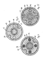
- strip-like projections 23 are provided to form a rotation in symmetrical distribution between the two housing covers.
- the strip-like projections 23 are received in correspondingly formed on the outer periphery of the thrust element 15 grooves 24, so that the thrust element 15 is positively fixed relative to the strip-like projections 23 and is guided against rotation at its longitudinal displacement to the strip-like projections 23.
- fastening openings 29 for receiving the screws used for fastening the housing cover 11 are also formed on the end faces of the housing 10.
- guide bearings 26 may be formed, for example, as guide bushes in the form of a ball bushing or a sliding bushing. This also ensures a rotationally secured guidance of the thrust element 15 in the housing 10.
- a profiled guide rail 27 and the thrust element 15 a the guide rail 27 comprehensive guide carriage 28 is arranged so that a co-operation of guide carriage 28 and guide rail 27 is also ensured a rotationally secured guidance of the thrust element 15 in the longitudinal movement in the housing 10.
Landscapes
- Engineering & Computer Science (AREA)
- General Engineering & Computer Science (AREA)
- Physics & Mathematics (AREA)
- Chemical & Material Sciences (AREA)
- Combustion & Propulsion (AREA)
- Electromagnetism (AREA)
- Power Engineering (AREA)
- Mechanical Engineering (AREA)
- Transmission Devices (AREA)
- Actuator (AREA)
Abstract
Description
- Die Erfindung betrifft einen elektromechanischen Linearantrieb mit einem Gehäuse und mit wenigstens einer einen stirnseitigen Gehäusedeckel in einem Durchbruch durchgreifenden, aus dem Gehäuse einseitig hervorstehenden und von einem im Inneren des Gehäuses längsverschiebbar angeordneten Schubelement getragenen Kolbenstange, wobei das Schubelement zu seiner Verschiebung von einer mittels eines Antriebes angetriebenen Antriebsstange getragen und die Kolbenstange exzentrisch zur Antriebsstange angeordnet ist.
- Ein elektromechanischer Linearantrieb zur Erzeugung translatorischer Vorschubbewegungen mit den vorgenannten Merkmalen ist aus der
EP 1 496 600 A2 bekannt. In dem Gehäuse ist eine unter der Wirkung eines als Stator und Rotor ausgebildeten Antriebs drehbare Antriebsstange in den beiden das Gehäuse verschließenden Gehäusedeckeln gelagert. Auf der mit einem Außengewinde versehenen Antriebsstange ist eine Gewindemutter als Schubelement geführt, die mit einer gabelförmigen Stellstange fest verbunden ist, deren Gabelschenkel zwei exzentrisch zur Antriebsstange angeordnete Kolbenstangen bilden, die den zugeordneten Gehäusedeckel in jeweiligen Durchbrüchen durchgreifen. Bei Verdrehung der Antriebsstange verschiebt sich die das Schubelement bildende Gewindemutter auf dem Außengewinde der Antriebsstange und bewirkt so ein Ausfahren beziehungsweise Einfahren der Kolbenstangen. - Mit dem bekannten Linearantrieb ist der Nachteil verbunden, dass sich die Kolbenstangen bei der Verschiebung der Gewindemutter in den Durchbrüchen der Gehäusedeckel abstützen, sodass die Durchbrüche als Verdrehsicherung für den Antrieb wie auch die mit den Kolbenstangen verbundene Last wirken, was mit einer entsprechenden Beanspruchung der Kolbenstangen beziehungsweise der Durchbrüche in den Gehäusedeckeln verbunden ist.
- Der Erfindung liegt daher die Aufgabe zugrunde, einen Linearantrieb mit den eingangs genannten, gattungsgemäßen Merkmalen derart weiterzubilden, dass die Beanspruchung von Kolbenstangen und/oder Gehäusedeckel durch die zu bewegende Last verringert ist.
- Die Lösung dieser Aufgabe ergibt sich einschließlich vorteilhafter Ausgestaltungen und Weiterbildungen der Erfindung aus dem Inhalt der Patentansprüche, welche dieser Beschreibung nachgestellt sind.
- Die Erfindung sieht hierzu vor, dass das die wenigstens eine Kolbenstange tragende Schubelement gegenüber dem Gehäuse mit einer mittels an Gehäuse und Schubelement jeweils angeordneter, ineinander greifender Führungselemente ausgebildeten kraftübertragenen Verdrehsicherung geführt ist. Mit der Erfindung ist der Vorteil verbunden, dass das Schubelement gegenüber dem Gehäuse verdrehgesichert geführt ist, sodass über die Last und die Kolbenstangen auf das Schubelement oder über die Antriebsstange eingetragene hohe Drehmomente von dem Schubelement aufgenommen und in das Gehäuse abgeleitet werden können. Da das Schubelement an der Stelle der Kraftübertragung auf das Gehäuse geführt und gehalten ist, ist die effektive Länge der Antriebsstange zwischen deren Lagerung und dem Schubelement im Hinblick auf denkbare Knickfälle durch hohe Lasten stark reduziert. Da die Kolbenstange beziehungsweise die Kolbenstangen nicht der Verdrehsicherung dienen, können schließlich in vorteilhafter Weise die Kolbenstange beziehungsweise die Kolbenstangen in nicht weiter beanspruchten Kolbenstangenlagern, beispielsweise in Form von Gleitlagern, in dem Gehäusedeckel geführt sein und zur Übertragung sehr hoher Kräfte herangezogen werden.
- Gemäß einem Ausführungsbeispiel der Erfindung kann zunächst in einer einfachen Ausgestaltung vorgesehen sein, dass die Verdrehsicherung aus wenigstens einem an der Innenwandung des Gehäuses ausgebildeten leistenartigen Vorsprung und aus wenigstens einer an dem Schubelement ausgebildeten, den Vorsprung passend aufnehmenden Nut besteht.
- Nach einem abgewandelten Ausführungsbeispiel der Erfindung kann vorgesehen sein, dass die Verdrehsicherung aus wenigstens einer an der Innenwandung des Gehäuses befestigten Führungsschiene und aus wenigstens einem an dem Schubelement angeordneten Führungswagen besteht, wobei der Führungswagen an der Führungsschiene mittels zusätzlicher reibungsmindernder Führungsmittel geführt sein kann, die nach Ausführungsbeispielen der Erfindung aus einer Rollen- oder Kugelführung bestehen können. Damit ist eine Leichtgängigkeit bei der Bewegung des von der Gewindespindel angetriebenen Schubelements im Gehäuse verbunden.
- Soweit in einer alternativen Ausführungsform der Erfindung vorgesehen ist, dass die Verdrehsicherung aus wenigstens einer in den stirnseitigen Gehäusedeckeln beidseitig festgelegten Führungsstange besteht, die in einem an dem Schubelement ausgebildeten Führungslager aufgenommen ist, ist mit dieser in das Innere des Gehäuses verlegten, aufgrund der beidseitigen Fixierung der Führungsstangen in den Gehäusedeckeln eine große Stabilität aufweisenden Verdrehsicherung der Vorteil verbunden, dass nur äußerst geringe Verdrehwinkel auftreten können. Somit ist der erfindungsgemäße Linearantrieb für präzise Positionieraufgaben hinsichtlich der an der Kolbenstange beziehungsweise an den Kolbenstangen angreifenden Nutzlast geeignet. Hierbei kann die Gleitfähigkeit des Schubelements in dem Gehäuse dadurch verbessert werden, dass in dem Schubelement wenigstens eine die Führungsstange in sich aufnehmende Führungsbuchse als Führungslager angeordnet ist, die als Gleitbuchse oder alternativ als Kugelbuchse ausgeführt sein kann. Es ist vorteilhaft, wenn in symmetrischer Anordnung zur Längsachse der Gewindespindel eine Mehrzahl von Führungsstangen und entsprechend angeordneten Führungslagern beziehungsweise Führungsbuchsen am Schubelement angeordnet sind.
- Für die Realisierung der Erfindung ist die Anbringung einer Kolbenstange an dem Schubelement ausreichend. Nach einem Ausführungsbeispiel der Erfindung kann jedoch vorgesehen sein, dass an dem Schubelement eine Mehrzahl von aus dem Gehäuse hervorstehenden Kolbenstangen angeordnet ist. Hierzu sind zur Verwirklichung der Erfindung zwei Kolbenstangen ausreichend. Es können jedoch auch mehr als zwei Kolbenstangen in einer beliebigen Anordnung relativ zur Antriebsstange vorgesehen sein.
- Vorzugsweise ist nach einem Ausführungsbeispiel der Erfindung vorgesehen, dass die mehreren Kolbenstangen in einer symmetrischen Anordnung bezüglich der Antriebsstange vorgesehen sind. Hiermit ist in vorteilhafter Weise die Entstehung und Einwirkung von Kippmomenten auf die Bestandteile des elektromechanischen Linearantriebs ausgeschlossen.
- Nach einem Ausführungsbeispiel der Erfindung ist vorgesehen, dass die Antriebsstange in einer aus der
EP 1 496 600 A2 an sich bekannten Weise beidseitig in den die Stirnseiten des Gehäuses verschließenden Gehäusedeckeln gelagert ist. - Soweit bei einer Ausbildung der Antriebsstange als Spindeltrieb die Drehzahl der Gewindespindel im allgemeinen durch deren frei tragende Länge, das heißt den Stützabstand ihrer Endlager bestimmt ist, ist nach einem Ausführungsbeispiel der Erfindung vorgesehen, dass die Gewindespindel zwischen ihren Endlagerungen an den Gehäusedeckeln mittels wenigstens eines weiteren, im Inneren des Gehäuses angeordneten Lagers abgestützt ist; hiermit ist der Vorteil einer dadurch möglichen Drehzahlerhöhung verbunden.
- Das erfindungsgemäße Konzept lässt sich nach Ausführungsbeispielen der Erfindung bei den beiden eingangs beschriebenen und zum Stand der Technik zählenden Antriebskonzepten verwirklichen, nämlich sowohl bei dem nach Art eines Linearmotors aufgebauten Antriebsmechanismus als auch bei dem als Spindeltrieb ausgebildeten Antriebsmechanismus. Insbesondere bei einem Spindeltrieb als Antriebsmechanismus kommt der erfindungsgemäße Aspekt einer beidseitigen Lagerung der Gewindespindel in den beiden stirnseitigen Gehäusedeckeln zum Tragen, da damit die Gewindespindel wesentlich geringeren Einschränkungen hinsichtlich Drehzahl und Ausfahrgeschwindigkeit unterliegt.
- Im Rahmen der Erfindung kann vorgesehen sein, dass die Gewindespindel als Trapezgewindespindel ausgebildet ist, womit die Vorteile einer Selbsthemmung und großen Aktionskraft verbunden sind. Alternativ kann vorgesehen sein, dass die Gewindespindel als Kugelumlaufspindel ausgebildet ist, womit eine hohe Präzision und Positioniergenauigkeit verbunden sind. Auch andere Spindeltypen sind ohne Einschränkungen bei der Erfindung einsetzbar.
- Im Hinblick auf unterschiedliche Einsatzbedingungen kann vorgesehen sein, dass die Gewindespindel in den stirnseitigen Gehäusedeckeln mit einem eine Temperaturdehnung der Gewindespindel berücksichtigenden axialen Spiel gelagert ist. Im Einzelnen kann dabei vorgesehen sein, dass wenigstens ein Ende der Gewindespindel einem an dem Gehäusedeckel angeordneten Loslager gehalten ist.
- Im Rahmen einer Verwirklichung der Erfindung kann die Gewindespindel in an sich bekannter Weise an den Elektromotor über ein zwischengeschaltetes Getriebe angeschlossen sein; es ist aber in Abhängigkeit von der Anordnung des Motors auch ein Direktantrieb der Gewindespindel denkbar.
- Soweit der Motor am Gehäuse angeflanscht sein kann, können Motor beziehungsweise Getriebe axial, gewinkelt oder parallel am Antriebsdeckel angeflanscht und gegebenenfalls mit einer mit der Gewindespindel verbundenen Antriebswelle gekoppelt sein, wie dies aus verschiedenen zum Stand der Technik zählenden Ausführungsformen bekannt ist.
- In der Zeichnung sind Ausführungsbeispiele der Erfindung wiedergegeben, welches nachstehend beschrieben sind. Es zeigen:
- Fig. 1
- einen elektromechanischen Linearantrieb in Spindeltrieb-Bauweise mit zwei Kolbenstangen in einer schematischen Schnittansicht,
- Fig. 2
- den Gegenstand der
Figur 1 mit einem als Linearmotor ausgebildeten Antriebskonzept, - Fig. 3
- eine Stirnansicht des im Gehäuse verdrehgesichert geführten Schubelements als Teil des elektromechanischen Linearantriebs gemäß
Figuren 1 oder 2 .. - Fig. 4
- eine alternative Verdrehsicherung für das Schubelement gemäß
Figur 3 , - Fig. 5
- eine wiederum alternative Ausführungsform der Verdrehsicherung für das Schubelement entsprechend
Figur 3 . - Wie sich zunächst aus der
Figur 1 ergibt, ist ein im wesentlichen zylindrisches Gehäuse 10 durch zwei stirnseitig aufgesetzte und das Gehäuse 10 verschließende Gehäusedeckel 11 verschlossen, wobei die Gehäusedeckel 11 mittels Befestigungsschrauben mit dem Gehäuse 10 verbunden sind. Im Inneren des Gehäuses 10 ist eine das Gehäuse durchsetzende Gewindespindel 12 als Antriebsstange angeordnet, die auf der einen, bei dem dargestellten Ausführungsbeispiel linken Gehäuseseite mit einem Antriebsansatz 13 den zugeordneten Gehäusedeckel 11 durchgreift, so dass über einen an den Antriebsansatz 13 angeschlossenen, nicht dargestellten Elektromotor die Gewindespindel 12 in Drehung versetzt werden kann. Die Gewindespindel 12 ist dabei in beiden Gehäusedeckeln 11 in geeigneter Weise in zugeordneten Lagern gelagert. Die Lagerung erfolgt über ein Festlager 18 und ein Loslager 19, das ein Axialspiel 20 zwischen dem stirnseitigen Ende der Gewindespindel 12 und dem zugeordneten Gehäusedeckel 11 zulässt, um beispielsweise einer etwaigen temperaturbedingten Ausdehnung der Gewindespindel 12 Rechnung zu tragen. - Auf der Gewindespindel 12 ist eine Gewindemutter 14 geführt, die mit einem die Gewindespindel 12 umgreifenden Schubelement 15 verbunden ist derart, dass bei Drehung der Gewindespindel 12 das Schubelement 15 unter der Wirkung der Gewindemutter 14 in dem Gehäuse 10 längsverschoben wird. An dem Schubelement 15 sind bei dem in der
Figur 1 dargestellten Ausführungsbeispiel in einer symmetrischen Anordnung zwei Kolbenstangen 16 in einer exzentrischen Lage zur Gewindespindel 12 befestigt, wobei die Kolbenstangen 16 den zugeordneten Gehäusedeckel 11 in entsprechend vorgesehenen, insbesondere als Gleitlager ausbildeten Kolbenstangenlagern 17 durchgreifen, darin geführt sind und frei über das Gehäuse 10 hervorstehen, so dass in einer nicht dargestellten, an sich aber bekannten Weise am Ende der Kolbenstangen 16 eine Nutzlast angeschlagen werden kann. - Das in
Figur 2 dargestellte Ausführungsbeispiel unterscheidet sich von dem zuvor beschriebenen Ausführungsbeispiel gemäßFigur 1 in dem Antriebskonzept, welches auf dem Prinzip eines Linearmotors beruht. Hierbei ist zwischen den Gehäusedeckeln 11 eine feststehende Magnetstange 21 als Antriebsstange angeordnet, die als Stator des Linearmotors dient. Mit dem Schubelement 15 als Träger der Kolbenstangen 16 ist ein eine Spulenanordnung aufweisender Läufer 22 verbunden, der sich aufgrund einer entsprechend erzeugten Magnetfeldänderung der Spule längs der Magnetstange 21 bewegt. - Soweit es erfindungsgemäß von Bedeutung ist, dass das Schubelement 15 in dem Gehäuse 10 verdrehgesichert geführt ist, sind in den
Figuren 3 bis 5 Ausführungsbeispiele hinsichtlich der Ausbildung einer solchen Verdrehsicherung dargestellt. - Bei dem in
Figur 3 dargestellten Ausführungsbeispiel sind zur Ausbildung einer Verdrehsicherung in symmetrischer Verteilung zwischen den beiden Gehäusedeckeln 11 verlaufende und sich durch das Gehäuse 10 erstreckende leistenartige Vorsprünge 23 vorgesehen. Die leistenartige Vorsprünge 23 sind in entsprechend am äußeren Umfang des Schubelements 15 ausgebildeten Nuten 24 aufgenommen, so dass das Schubelement 15 formschlüssig gegenüber den leistenartigen Vorsprüngen 23 festgelegt ist und bei seiner Längsverschiebung an den leistenartige Vorsprüngen 23 verdrehgesichert geführt ist. Im Bereich der leistenartigen Vorsprünge 23 sind an den Stirnflächen des Gehäuses 10 noch Befestigungsöffnungen 29 zur Aufnahme der zur Befestigung der Gehäusedeckel 11 verwendeten Schrauben ausgebildet. - Alternativ zu den Vorsprüngen 23 sind bei dem in
Figur 4 dargestellten Ausführungsbeispiel zur Ausbildung der Verdrehsicherung zwischen den Gehäusedeckeln 11 verlaufende Führungsstangen 25 angeordnet, die in in dem Schubelement 15 ausgebildeten Führungslagern 26 aufgenommen sind. Diese Führungslager 26 können beispielsweise als Führungsbuchsen in Form einer Kugelbuchse oder einer Gleitbuchse ausgebildet sein. Auch hierdurch ist eine verdrehgesicherte Führung des Schubelements 15 im Gehäuse 10 gewährleistet. - Gemäß
Figur 5 schließlich sind zur Ausbildung der Verdrehsicherung am Gehäuse 10 eine profilierte Führungsschiene 27 und am Schubelement 15 ein die Führungsschiene 27 umfassender Führungswagen 28 angeordnet, so daß durch Zusammenwirken von Führungswagen 28 und Führungsschiene 27 ebenfalls eine verdrehgesicherte Führung des Schubelements 15 bei dessen Längsbewegung im Gehäuse 10 gewährleistet ist. - Die in der vorstehenden Beschreibung, den Patentansprüchen, der Zusammenfassung und der Zeichnung offenbarten Merkmale des Gegenstandes dieser Unterlagen können sowohl einzeln als auch in beliebigen Kombinationen untereinander für die Verwirklichung der Erfindung in ihren verschiedenen Ausführungsformen wesentlich sein.
Claims (15)
- Elektromechanischer Linearantrieb mit einem Gehäuse (10) und mit wenigstens einer einen stirnseitigen Gehäusedeckel (11) in einem Durchbruch durchgreifenden, aus dem Gehäuse (10) einseitig hervorstehenden und von einem im Inneren des Gehäuses (10) längsverschiebbar angeordneten Schubelement (15) getragenen Kolbenstange (16), wobei das Schubelement (15) zu seiner Verschiebung von einer mittels eines Antriebes angetriebenen Antriebsstange getragen und die Kolbenstange (16) exzentrisch zur Antriebsstange angeordnet ist, dadurch gekennzeichnet, dass das die wenigstens eine Kolbenstange (16) tragende Schubelement (15) gegenüber dem Gehäuse (10) mit einer mittels an Gehäuse (10) und Schubelement (15) jeweils angeordneter, ineinander greifender Führungselemente ausgebildeten kraftübertragenen Verdrehsicherung geführt ist.
- Elektromechanischer Linearantrieb nach Anspruch 1, dadurch gekennzeichnet, dass die Verdrehsicherung aus wenigstens einem an der Innenwandung des Gehäuses (10) ausgebildeten leistenartigen Vorsprung (23) und aus wenigstens einer an dem Schubelement (15) ausgebildeten, den Vorsprung (23) passend aufnehmenden Nut (24) besteht.
- Elektromechanischer Linearantrieb nach Anspruch 1, dadurch gekennzeichnet, dass die Verdrehsicherung aus wenigstens einer an der Innenwandung des Gehäuses (10) befestigten Führungsschiene (27) und aus wenigstens einem an dem Schubelement (15) angeordneten Führungswagen (28) besteht.
- Elektromechanischer Linearantrieb nach Anspruch 3, dadurch gekennzeichnet, dass der Führungswagen (28) an der Führungsschiene (27) mittels zusätzlicher reibungsmindernder Führungsmittel geführt ist.
- Elektromechanischer Linearantrieb nach Anspruch 4, dadurch gekennzeichnet, dass die Führungsmittel aus einer Rollen- oder Kugelführung bestehen
- Elektromechanischer Linearantrieb nach Anspruch 1, dadurch gekennzeichnet, dass die Verdrehsicherung aus wenigstens einer in den stirnseitigen Gehäusedeckeln (11) beidseitig festgelegten Führungsstange (25) besteht, die in einem an dem Schubelement (15) ausgebildeten Führungslager (26) aufgenommen ist.
- Elektromechanischer Linearantrieb nach Anspruch 6, dadurch gekennzeichnet, dass in dem Schubelement (15) wenigstens eine die Führungsstange (25) in sich aufnehmende Gleitbuchse angeordnet ist.
- Elektromechanischer Linearantrieb nach Anspruch 6, dadurch gekennzeichnet, dass in dem Schubelement (15) wenigstens eine die Führungsstange (25) in sich aufnehmende Kugelbuchse angeordnet ist.
- Elektromechanischer Linearantrieb nach einem der Ansprüche 6 bis 8 dadurch gekennzeichnet, dass in symmetrischer Anordnung zur Längsachse der Gewindespindel (12) eine Mehrzahl von Führungsstangen (25) und entsprechend angeordneten Führungslagern (26) am Schubelement (15) angeordnet sind.
- Elektromechanischer Linearantrieb nach einem der Ansprüche 1 bis 9, dadurch gekennzeichnet, dass an dem Schubelement (15) eine Mehrzahl von aus dem Gehäuse (10) hervorstehenden Kolbenstangen (16) angeordnet ist.
- Elektromechanischer Linearantrieb nach Anspruch 10, dadurch gekennzeichnet, dass die mehreren Kolbenstangen (16) in einer symmetrischen Anordnung bezüglich der Antriebsstange vorgesehen sind.
- Elektromechanischer Linearantrieb nach einem der Ansprüche 1 bis 11, dadurch gekennzeichnet, dass die Antriebsstange beidseitig in die Stirnseiten des Gehäuses (10) verschließenden Gehäusedeckeln (11) gelagert ist.
- Elektromechanischer Linearantrieb nach Anspruch 12, dadurch gekennzeichnet, dass die Antriebsstange zwischen ihren Endlagerungen an den Gehäusedeckeln (11) mittels wenigstens eines weiteren, im Inneren des Gehäuses (10) angeordneten Lagers abgestützt ist.
- Elektromechanischer Linearantrieb nach einem der Ansprüche 1 bis 13, dadurch gekennzeichnet, dass der Antriebsmechanismus als Spindeltrieb mit einer drehbaren Gewindespindel (12) als Antriebsstange ausgebildet ist und das Schubelement (15) durch die Drehung der Gewindespindel (12) längsverschiebbar ist.
- Elektromechanischer Linearantrieb nach einem der Ansprüche 1 bis 11, dadurch gekennzeichnet, dass der Antriebsmechanismus als Linearmotor ausgebildet und die Antriebsstange als Magnetstange (21) ausgebildet und das Schubelement (15) mittels eines eine Spulenanordnung aufweisenden Läufers (22) entlang der Magnetstange (21) längsverschiebbar eingerichtet ist.
Applications Claiming Priority (1)
| Application Number | Priority Date | Filing Date | Title |
|---|---|---|---|
| DE102009020040 | 2009-05-05 |
Publications (3)
| Publication Number | Publication Date |
|---|---|
| EP2249461A2 true EP2249461A2 (de) | 2010-11-10 |
| EP2249461A3 EP2249461A3 (de) | 2014-07-16 |
| EP2249461B1 EP2249461B1 (de) | 2017-02-01 |
Family
ID=42235701
Family Applications (1)
| Application Number | Title | Priority Date | Filing Date |
|---|---|---|---|
| EP10004743.0A Active EP2249461B1 (de) | 2009-05-05 | 2010-05-05 | Elektromechanischer Linearantrieb |
Country Status (3)
| Country | Link |
|---|---|
| US (1) | US8314519B2 (de) |
| EP (1) | EP2249461B1 (de) |
| ES (1) | ES2622838T3 (de) |
Cited By (1)
| Publication number | Priority date | Publication date | Assignee | Title |
|---|---|---|---|---|
| EP2767729A1 (de) * | 2013-02-19 | 2014-08-20 | Honeywell International Inc. | Aktuator mit handhabungssicherem Positionsrückführungsmechanismus |
Families Citing this family (19)
| Publication number | Priority date | Publication date | Assignee | Title |
|---|---|---|---|---|
| US8272284B2 (en) * | 2006-10-10 | 2012-09-25 | Ntn Corporation | Electronically driven linear actuator |
| TW200918788A (en) * | 2007-10-26 | 2009-05-01 | Univ Nat Taiwan | Screw-type inerter mechanism |
| FR2924538B1 (fr) * | 2007-11-30 | 2010-01-22 | Sagem Defense Securite | Procede de surveillance du rendement d'un actionneur electromecanique du type rotolineaire |
| ITRM20120562A1 (it) * | 2012-11-15 | 2014-05-16 | Umbra Cuscinetti Spa | Attuatore elettromeccanico lineare. |
| ITRM20120587A1 (it) * | 2012-11-22 | 2014-05-23 | Umbra Cuscinetti Spa | Attuatore elettromeccanico lineare con antirotazione integrata. |
| TWI499731B (zh) * | 2013-01-17 | 2015-09-11 | Timotion Technology Co Ltd | 線性傳動裝置改良 |
| CN104852508A (zh) * | 2015-05-15 | 2015-08-19 | 燕山大学 | 一种双出杆电动缸 |
| KR101907397B1 (ko) * | 2017-04-26 | 2018-10-12 | 주식회사 세진아이지비 | 서보 실린더 |
| US10583917B2 (en) | 2017-05-18 | 2020-03-10 | Goodrich Corporation | Electromechanical actuator disconnect |
| US20200056685A1 (en) * | 2018-08-17 | 2020-02-20 | Owen Riehle | Actuator |
| WO2021000184A1 (zh) * | 2019-06-30 | 2021-01-07 | 瑞声声学科技(深圳)有限公司 | 振动电机 |
| JP7410791B2 (ja) * | 2020-04-28 | 2024-01-10 | ニデックインスツルメンツ株式会社 | アクチュエータ |
| CN113572333B (zh) * | 2020-04-28 | 2024-03-29 | 日本电产三协株式会社 | 致动器 |
| CN216356413U (zh) * | 2020-07-10 | 2022-04-19 | 日本电产株式会社 | 振动马达及触觉器件 |
| JP2022049071A (ja) * | 2020-09-16 | 2022-03-29 | 株式会社東芝 | 振動発電機 |
| JP7559548B2 (ja) * | 2020-12-25 | 2024-10-02 | ニデック株式会社 | 振動モータ、および、触覚デバイス |
| JP2022102878A (ja) * | 2020-12-25 | 2022-07-07 | 日本電産株式会社 | 振動モータ、および、触覚デバイス |
| US12535467B2 (en) | 2022-07-29 | 2026-01-27 | Valco Instruments Company, Inc. | Linear actuator for chromatography |
| CN120915084A (zh) * | 2024-05-06 | 2025-11-07 | 比亚迪股份有限公司 | 直线电机、悬架系统及车辆 |
Citations (1)
| Publication number | Priority date | Publication date | Assignee | Title |
|---|---|---|---|---|
| EP1496600A2 (de) | 2003-07-11 | 2005-01-12 | SAIA-Burgess Dresden GmbH | Linearantrieb |
Family Cites Families (14)
| Publication number | Priority date | Publication date | Assignee | Title |
|---|---|---|---|---|
| US5440183A (en) * | 1991-07-12 | 1995-08-08 | Denne Developments, Ltd. | Electromagnetic apparatus for producing linear motion |
| US5257014A (en) * | 1991-10-31 | 1993-10-26 | Caterpillar Inc. | Actuator detection method and apparatus for an electromechanical actuator |
| DE4222365B4 (de) | 1992-07-08 | 2007-03-01 | Siemens Ag | Stellelement |
| WO1999018649A1 (en) * | 1997-10-04 | 1999-04-15 | Z & D Limited | Linear motor compressor |
| US6084326A (en) * | 1998-02-04 | 2000-07-04 | Smc Kabushiki Kaisha | Actuator |
| DE19853942C1 (de) * | 1998-11-24 | 2000-07-13 | Festo Ag & Co | Elektrischer Linearantrieb |
| JP3862885B2 (ja) * | 1999-03-09 | 2006-12-27 | 山洋電気株式会社 | シリンダ型リニア同期モータ |
| JP4366849B2 (ja) * | 2000-08-31 | 2009-11-18 | 株式会社デンソー | リニア圧縮機 |
| JP2004312881A (ja) | 2003-04-07 | 2004-11-04 | Smc Corp | アクチュエータ |
| ITTO20030106U1 (it) * | 2003-07-07 | 2005-01-08 | Skf Ab | Attuatore elettromeccanico lineare a vite per un freno di stazionamento |
| JP2005036899A (ja) * | 2003-07-15 | 2005-02-10 | Smc Corp | 電動アクチュエータ |
| DE50308288D1 (de) * | 2003-12-04 | 2007-11-08 | Festo Ag & Co | Mikrowellenwegmesssystem für elektrodynamischen Direktantrieb |
| ITTO20040871A1 (it) * | 2004-12-13 | 2005-03-13 | Skf Ab | Attuatore elettromeccanico lineare a vite per un freno di stazionamento. |
| ATE524866T1 (de) | 2006-11-30 | 2011-09-15 | Sonceboz Sa | Linearantrieb durch spindelantrieb |
-
2010
- 2010-05-05 ES ES10004743.0T patent/ES2622838T3/es active Active
- 2010-05-05 EP EP10004743.0A patent/EP2249461B1/de active Active
- 2010-05-05 US US12/774,058 patent/US8314519B2/en not_active Expired - Fee Related
Patent Citations (1)
| Publication number | Priority date | Publication date | Assignee | Title |
|---|---|---|---|---|
| EP1496600A2 (de) | 2003-07-11 | 2005-01-12 | SAIA-Burgess Dresden GmbH | Linearantrieb |
Cited By (3)
| Publication number | Priority date | Publication date | Assignee | Title |
|---|---|---|---|---|
| EP2767729A1 (de) * | 2013-02-19 | 2014-08-20 | Honeywell International Inc. | Aktuator mit handhabungssicherem Positionsrückführungsmechanismus |
| US9512910B2 (en) | 2013-02-19 | 2016-12-06 | Honeywell International Inc. | Actuator including handling-proof position feedback mechanism |
| US9777812B2 (en) | 2013-02-19 | 2017-10-03 | Honeywell International Inc. | Actuator including handling-proof position feedback mechanism |
Also Published As
| Publication number | Publication date |
|---|---|
| ES2622838T3 (es) | 2017-07-07 |
| EP2249461A3 (de) | 2014-07-16 |
| US20110234021A1 (en) | 2011-09-29 |
| US8314519B2 (en) | 2012-11-20 |
| EP2249461B1 (de) | 2017-02-01 |
Similar Documents
| Publication | Publication Date | Title |
|---|---|---|
| EP2249461B1 (de) | Elektromechanischer Linearantrieb | |
| EP2733830B1 (de) | Hubdrehvorrichtung | |
| DE102007043391A1 (de) | Aktuator mit verlagerbarem Ausleger | |
| DE112006002312B4 (de) | Mikrostellglied | |
| EP4365060B1 (de) | Lenksäule für ein kraftfahrzeug | |
| EP3044855B1 (de) | Linearaktuator | |
| DE29919214U1 (de) | Elektromotorischer Möbelantrieb | |
| DE2220058A1 (de) | Mechanische Schub- und Zugvorrichtung | |
| DE102017209563A1 (de) | Loslager, Lenkgetriebe und Lenksystem | |
| EP3315154A1 (de) | Zweistufiger teleskopspindelantrieb | |
| DE202009015840U1 (de) | Linearaktuator | |
| DE102016100783A1 (de) | Winde für einen Zugstrang | |
| DE102013107378A1 (de) | Antriebsvorrichtung | |
| WO2017005258A1 (de) | Gewindetrieb | |
| EP2891824B1 (de) | Schieber | |
| EP0345536A2 (de) | Linearführung | |
| EP3405698B1 (de) | Aktuator mit hohlschnecke | |
| EP1619281A1 (de) | Legebarrenantrieb in einer Wirkmaschine | |
| DE102007038264A1 (de) | Aktiver Stabilisator zur Wankstabilisierung | |
| DE102018126071A1 (de) | Linearaktor, insbesondere für eine Fahrzeugkupplung | |
| EP2072861B1 (de) | Verdrehsicherung mit Toleranzausgleich | |
| DE102012108635A1 (de) | Vorrichtung zum Umstellen von Zungenschienen einer Weiche | |
| DE102018205781B4 (de) | Antriebseinrichtung | |
| DE102013219037C5 (de) | Türschließer | |
| EP2292942B1 (de) | Linearstellglied mit Stützlager |
Legal Events
| Date | Code | Title | Description |
|---|---|---|---|
| PUAI | Public reference made under article 153(3) epc to a published international application that has entered the european phase |
Free format text: ORIGINAL CODE: 0009012 |
|
| AK | Designated contracting states |
Kind code of ref document: A2 Designated state(s): AL AT BE BG CH CY CZ DE DK EE ES FI FR GB GR HR HU IE IS IT LI LT LU LV MC MK MT NL NO PL PT RO SE SI SK SM TR |
|
| AX | Request for extension of the european patent |
Extension state: BA ME RS |
|
| PUAL | Search report despatched |
Free format text: ORIGINAL CODE: 0009013 |
|
| AK | Designated contracting states |
Kind code of ref document: A3 Designated state(s): AL AT BE BG CH CY CZ DE DK EE ES FI FR GB GR HR HU IE IS IT LI LT LU LV MC MK MT NL NO PL PT RO SE SI SK SM TR |
|
| AX | Request for extension of the european patent |
Extension state: BA ME RS |
|
| RIC1 | Information provided on ipc code assigned before grant |
Ipc: F16H 25/20 20060101ALI20140611BHEP Ipc: H02K 7/06 20060101AFI20140611BHEP |
|
| 17P | Request for examination filed |
Effective date: 20141218 |
|
| RBV | Designated contracting states (corrected) |
Designated state(s): AL AT BE BG CH CY CZ DE DK EE ES FI FR GB GR HR HU IE IS IT LI LT LU LV MC MK MT NL NO PL PT RO SE SI SK SM TR |
|
| GRAP | Despatch of communication of intention to grant a patent |
Free format text: ORIGINAL CODE: EPIDOSNIGR1 |
|
| INTG | Intention to grant announced |
Effective date: 20161007 |
|
| GRAS | Grant fee paid |
Free format text: ORIGINAL CODE: EPIDOSNIGR3 |
|
| GRAA | (expected) grant |
Free format text: ORIGINAL CODE: 0009210 |
|
| AK | Designated contracting states |
Kind code of ref document: B1 Designated state(s): AL AT BE BG CH CY CZ DE DK EE ES FI FR GB GR HR HU IE IS IT LI LT LU LV MC MK MT NL NO PL PT RO SE SI SK SM TR |
|
| REG | Reference to a national code |
Ref country code: GB Ref legal event code: FG4D Free format text: NOT ENGLISH |
|
| REG | Reference to a national code |
Ref country code: CH Ref legal event code: EP Ref country code: AT Ref legal event code: REF Ref document number: 866306 Country of ref document: AT Kind code of ref document: T Effective date: 20170215 |
|
| REG | Reference to a national code |
Ref country code: IE Ref legal event code: FG4D Free format text: LANGUAGE OF EP DOCUMENT: GERMAN |
|
| REG | Reference to a national code |
Ref country code: DE Ref legal event code: R096 Ref document number: 502010013133 Country of ref document: DE |
|
| REG | Reference to a national code |
Ref country code: DE Ref legal event code: R081 Ref document number: 502010013133 Country of ref document: DE Owner name: PARKER HANNIFIN MANUFACTURING GERMANY GMBH & C, DE Free format text: FORMER OWNER: PARKER-ORIGA GMBH, 70794 FILDERSTADT, DE |
|
| REG | Reference to a national code |
Ref country code: NL Ref legal event code: FP |
|
| REG | Reference to a national code |
Ref country code: SE Ref legal event code: TRGR |
|
| RAP2 | Party data changed (patent owner data changed or rights of a patent transferred) |
Owner name: PARKER HANNIFIN MANUFACTURING GERMANY GMBH & CO. K |
|
| REG | Reference to a national code |
Ref country code: FR Ref legal event code: PLFP Year of fee payment: 8 |
|
| REG | Reference to a national code |
Ref country code: LT Ref legal event code: MG4D |
|
| REG | Reference to a national code |
Ref country code: GB Ref legal event code: 732E Free format text: REGISTERED BETWEEN 20170608 AND 20170614 |
|
| REG | Reference to a national code |
Ref country code: ES Ref legal event code: FG2A Ref document number: 2622838 Country of ref document: ES Kind code of ref document: T3 Effective date: 20170707 |
|
| PG25 | Lapsed in a contracting state [announced via postgrant information from national office to epo] |
Ref country code: LT Free format text: LAPSE BECAUSE OF FAILURE TO SUBMIT A TRANSLATION OF THE DESCRIPTION OR TO PAY THE FEE WITHIN THE PRESCRIBED TIME-LIMIT Effective date: 20170201 Ref country code: GR Free format text: LAPSE BECAUSE OF FAILURE TO SUBMIT A TRANSLATION OF THE DESCRIPTION OR TO PAY THE FEE WITHIN THE PRESCRIBED TIME-LIMIT Effective date: 20170502 Ref country code: FI Free format text: LAPSE BECAUSE OF FAILURE TO SUBMIT A TRANSLATION OF THE DESCRIPTION OR TO PAY THE FEE WITHIN THE PRESCRIBED TIME-LIMIT Effective date: 20170201 Ref country code: HR Free format text: LAPSE BECAUSE OF FAILURE TO SUBMIT A TRANSLATION OF THE DESCRIPTION OR TO PAY THE FEE WITHIN THE PRESCRIBED TIME-LIMIT Effective date: 20170201 Ref country code: NO Free format text: LAPSE BECAUSE OF FAILURE TO SUBMIT A TRANSLATION OF THE DESCRIPTION OR TO PAY THE FEE WITHIN THE PRESCRIBED TIME-LIMIT Effective date: 20170501 Ref country code: IS Free format text: LAPSE BECAUSE OF FAILURE TO SUBMIT A TRANSLATION OF THE DESCRIPTION OR TO PAY THE FEE WITHIN THE PRESCRIBED TIME-LIMIT Effective date: 20170601 |
|
| PG25 | Lapsed in a contracting state [announced via postgrant information from national office to epo] |
Ref country code: LV Free format text: LAPSE BECAUSE OF FAILURE TO SUBMIT A TRANSLATION OF THE DESCRIPTION OR TO PAY THE FEE WITHIN THE PRESCRIBED TIME-LIMIT Effective date: 20170201 Ref country code: BG Free format text: LAPSE BECAUSE OF FAILURE TO SUBMIT A TRANSLATION OF THE DESCRIPTION OR TO PAY THE FEE WITHIN THE PRESCRIBED TIME-LIMIT Effective date: 20170501 Ref country code: PT Free format text: LAPSE BECAUSE OF FAILURE TO SUBMIT A TRANSLATION OF THE DESCRIPTION OR TO PAY THE FEE WITHIN THE PRESCRIBED TIME-LIMIT Effective date: 20170601 Ref country code: LU Free format text: LAPSE BECAUSE OF NON-PAYMENT OF DUE FEES Effective date: 20170531 Ref country code: PL Free format text: LAPSE BECAUSE OF FAILURE TO SUBMIT A TRANSLATION OF THE DESCRIPTION OR TO PAY THE FEE WITHIN THE PRESCRIBED TIME-LIMIT Effective date: 20170201 |
|
| PG25 | Lapsed in a contracting state [announced via postgrant information from national office to epo] |
Ref country code: SK Free format text: LAPSE BECAUSE OF FAILURE TO SUBMIT A TRANSLATION OF THE DESCRIPTION OR TO PAY THE FEE WITHIN THE PRESCRIBED TIME-LIMIT Effective date: 20170201 Ref country code: RO Free format text: LAPSE BECAUSE OF FAILURE TO SUBMIT A TRANSLATION OF THE DESCRIPTION OR TO PAY THE FEE WITHIN THE PRESCRIBED TIME-LIMIT Effective date: 20170201 Ref country code: EE Free format text: LAPSE BECAUSE OF FAILURE TO SUBMIT A TRANSLATION OF THE DESCRIPTION OR TO PAY THE FEE WITHIN THE PRESCRIBED TIME-LIMIT Effective date: 20170201 |
|
| REG | Reference to a national code |
Ref country code: DE Ref legal event code: R097 Ref document number: 502010013133 Country of ref document: DE |
|
| PG25 | Lapsed in a contracting state [announced via postgrant information from national office to epo] |
Ref country code: DK Free format text: LAPSE BECAUSE OF FAILURE TO SUBMIT A TRANSLATION OF THE DESCRIPTION OR TO PAY THE FEE WITHIN THE PRESCRIBED TIME-LIMIT Effective date: 20170201 Ref country code: SM Free format text: LAPSE BECAUSE OF FAILURE TO SUBMIT A TRANSLATION OF THE DESCRIPTION OR TO PAY THE FEE WITHIN THE PRESCRIBED TIME-LIMIT Effective date: 20170201 |
|
| PLBE | No opposition filed within time limit |
Free format text: ORIGINAL CODE: 0009261 |
|
| STAA | Information on the status of an ep patent application or granted ep patent |
Free format text: STATUS: NO OPPOSITION FILED WITHIN TIME LIMIT |
|
| 26N | No opposition filed |
Effective date: 20171103 |
|
| PG25 | Lapsed in a contracting state [announced via postgrant information from national office to epo] |
Ref country code: MC Free format text: LAPSE BECAUSE OF FAILURE TO SUBMIT A TRANSLATION OF THE DESCRIPTION OR TO PAY THE FEE WITHIN THE PRESCRIBED TIME-LIMIT Effective date: 20170201 |
|
| REG | Reference to a national code |
Ref country code: IE Ref legal event code: MM4A |
|
| PG25 | Lapsed in a contracting state [announced via postgrant information from national office to epo] |
Ref country code: SI Free format text: LAPSE BECAUSE OF FAILURE TO SUBMIT A TRANSLATION OF THE DESCRIPTION OR TO PAY THE FEE WITHIN THE PRESCRIBED TIME-LIMIT Effective date: 20170201 |
|
| PG25 | Lapsed in a contracting state [announced via postgrant information from national office to epo] |
Ref country code: LU Free format text: LAPSE BECAUSE OF NON-PAYMENT OF DUE FEES Effective date: 20170505 |
|
| PG25 | Lapsed in a contracting state [announced via postgrant information from national office to epo] |
Ref country code: IE Free format text: LAPSE BECAUSE OF NON-PAYMENT OF DUE FEES Effective date: 20170505 |
|
| REG | Reference to a national code |
Ref country code: FR Ref legal event code: PLFP Year of fee payment: 9 |
|
| PG25 | Lapsed in a contracting state [announced via postgrant information from national office to epo] |
Ref country code: MT Free format text: LAPSE BECAUSE OF FAILURE TO SUBMIT A TRANSLATION OF THE DESCRIPTION OR TO PAY THE FEE WITHIN THE PRESCRIBED TIME-LIMIT Effective date: 20170201 |
|
| PG25 | Lapsed in a contracting state [announced via postgrant information from national office to epo] |
Ref country code: HU Free format text: LAPSE BECAUSE OF FAILURE TO SUBMIT A TRANSLATION OF THE DESCRIPTION OR TO PAY THE FEE WITHIN THE PRESCRIBED TIME-LIMIT; INVALID AB INITIO Effective date: 20100505 |
|
| PG25 | Lapsed in a contracting state [announced via postgrant information from national office to epo] |
Ref country code: CY Free format text: LAPSE BECAUSE OF NON-PAYMENT OF DUE FEES Effective date: 20170201 |
|
| PG25 | Lapsed in a contracting state [announced via postgrant information from national office to epo] |
Ref country code: MK Free format text: LAPSE BECAUSE OF FAILURE TO SUBMIT A TRANSLATION OF THE DESCRIPTION OR TO PAY THE FEE WITHIN THE PRESCRIBED TIME-LIMIT Effective date: 20170201 |
|
| PG25 | Lapsed in a contracting state [announced via postgrant information from national office to epo] |
Ref country code: TR Free format text: LAPSE BECAUSE OF FAILURE TO SUBMIT A TRANSLATION OF THE DESCRIPTION OR TO PAY THE FEE WITHIN THE PRESCRIBED TIME-LIMIT Effective date: 20170201 |
|
| PG25 | Lapsed in a contracting state [announced via postgrant information from national office to epo] |
Ref country code: AL Free format text: LAPSE BECAUSE OF FAILURE TO SUBMIT A TRANSLATION OF THE DESCRIPTION OR TO PAY THE FEE WITHIN THE PRESCRIBED TIME-LIMIT Effective date: 20170201 |
|
| PGFP | Annual fee paid to national office [announced via postgrant information from national office to epo] |
Ref country code: CZ Payment date: 20210427 Year of fee payment: 12 Ref country code: NL Payment date: 20210526 Year of fee payment: 12 |
|
| PGFP | Annual fee paid to national office [announced via postgrant information from national office to epo] |
Ref country code: GB Payment date: 20210527 Year of fee payment: 12 Ref country code: ES Payment date: 20210601 Year of fee payment: 12 Ref country code: CH Payment date: 20210527 Year of fee payment: 12 Ref country code: BE Payment date: 20210527 Year of fee payment: 12 Ref country code: AT Payment date: 20210421 Year of fee payment: 12 Ref country code: SE Payment date: 20210527 Year of fee payment: 12 |
|
| REG | Reference to a national code |
Ref country code: CH Ref legal event code: PL |
|
| REG | Reference to a national code |
Ref country code: SE Ref legal event code: EUG |
|
| REG | Reference to a national code |
Ref country code: NL Ref legal event code: MM Effective date: 20220601 |
|
| REG | Reference to a national code |
Ref country code: AT Ref legal event code: MM01 Ref document number: 866306 Country of ref document: AT Kind code of ref document: T Effective date: 20220505 |
|
| REG | Reference to a national code |
Ref country code: BE Ref legal event code: MM Effective date: 20220531 |
|
| GBPC | Gb: european patent ceased through non-payment of renewal fee |
Effective date: 20220505 |
|
| PG25 | Lapsed in a contracting state [announced via postgrant information from national office to epo] |
Ref country code: SE Free format text: LAPSE BECAUSE OF NON-PAYMENT OF DUE FEES Effective date: 20220506 Ref country code: LI Free format text: LAPSE BECAUSE OF NON-PAYMENT OF DUE FEES Effective date: 20220531 Ref country code: CZ Free format text: LAPSE BECAUSE OF NON-PAYMENT OF DUE FEES Effective date: 20220505 Ref country code: CH Free format text: LAPSE BECAUSE OF NON-PAYMENT OF DUE FEES Effective date: 20220531 Ref country code: AT Free format text: LAPSE BECAUSE OF NON-PAYMENT OF DUE FEES Effective date: 20220505 |
|
| PG25 | Lapsed in a contracting state [announced via postgrant information from national office to epo] |
Ref country code: GB Free format text: LAPSE BECAUSE OF NON-PAYMENT OF DUE FEES Effective date: 20220505 Ref country code: BE Free format text: LAPSE BECAUSE OF NON-PAYMENT OF DUE FEES Effective date: 20220531 |
|
| PG25 | Lapsed in a contracting state [announced via postgrant information from national office to epo] |
Ref country code: NL Free format text: LAPSE BECAUSE OF NON-PAYMENT OF DUE FEES Effective date: 20220601 |
|
| REG | Reference to a national code |
Ref country code: ES Ref legal event code: FD2A Effective date: 20230703 |
|
| P01 | Opt-out of the competence of the unified patent court (upc) registered |
Effective date: 20230524 |
|
| PG25 | Lapsed in a contracting state [announced via postgrant information from national office to epo] |
Ref country code: ES Free format text: LAPSE BECAUSE OF NON-PAYMENT OF DUE FEES Effective date: 20220506 |
|
| PGFP | Annual fee paid to national office [announced via postgrant information from national office to epo] |
Ref country code: DE Payment date: 20250529 Year of fee payment: 16 |
|
| PGFP | Annual fee paid to national office [announced via postgrant information from national office to epo] |
Ref country code: IT Payment date: 20250521 Year of fee payment: 16 |
|
| PGFP | Annual fee paid to national office [announced via postgrant information from national office to epo] |
Ref country code: FR Payment date: 20250526 Year of fee payment: 16 |
|
| REG | Reference to a national code |
Ref country code: DE Ref legal event code: R082 Ref document number: 502010013133 Country of ref document: DE Representative=s name: DIPAS PATENTANWALTS GMBH, DE |