EP2248974B1 - Charnière avec multiple points d'appui - Google Patents
Charnière avec multiple points d'appui Download PDFInfo
- Publication number
- EP2248974B1 EP2248974B1 EP10075377.1A EP10075377A EP2248974B1 EP 2248974 B1 EP2248974 B1 EP 2248974B1 EP 10075377 A EP10075377 A EP 10075377A EP 2248974 B1 EP2248974 B1 EP 2248974B1
- Authority
- EP
- European Patent Office
- Prior art keywords
- flap
- arm
- hinge
- pivot point
- guide arm
- Prior art date
- Legal status (The legal status is an assumption and is not a legal conclusion. Google has not performed a legal analysis and makes no representation as to the accuracy of the status listed.)
- Active
Links
- 230000001154 acute effect Effects 0.000 claims description 3
- 230000005484 gravity Effects 0.000 description 5
- 230000000694 effects Effects 0.000 description 3
- 238000010276 construction Methods 0.000 description 2
- 238000005192 partition Methods 0.000 description 2
- 230000001419 dependent effect Effects 0.000 description 1
- 230000002349 favourable effect Effects 0.000 description 1
- 210000000629 knee joint Anatomy 0.000 description 1
- 230000014759 maintenance of location Effects 0.000 description 1
- 230000000717 retained effect Effects 0.000 description 1
Images


Classifications
-
- E—FIXED CONSTRUCTIONS
- E05—LOCKS; KEYS; WINDOW OR DOOR FITTINGS; SAFES
- E05D—HINGES OR SUSPENSION DEVICES FOR DOORS, WINDOWS OR WINGS
- E05D3/00—Hinges with pins
- E05D3/06—Hinges with pins with two or more pins
- E05D3/16—Hinges with pins with two or more pins with seven parallel pins and four arms
-
- E—FIXED CONSTRUCTIONS
- E05—LOCKS; KEYS; WINDOW OR DOOR FITTINGS; SAFES
- E05F—DEVICES FOR MOVING WINGS INTO OPEN OR CLOSED POSITION; CHECKS FOR WINGS; WING FITTINGS NOT OTHERWISE PROVIDED FOR, CONCERNED WITH THE FUNCTIONING OF THE WING
- E05F1/00—Closers or openers for wings, not otherwise provided for in this subclass
- E05F1/08—Closers or openers for wings, not otherwise provided for in this subclass spring-actuated, e.g. for horizontally sliding wings
- E05F1/10—Closers or openers for wings, not otherwise provided for in this subclass spring-actuated, e.g. for horizontally sliding wings for swinging wings, e.g. counterbalance
- E05F1/12—Mechanisms in the shape of hinges or pivots, operated by springs
- E05F1/1246—Mechanisms in the shape of hinges or pivots, operated by springs with a coil spring perpendicular to the pivot axis
- E05F1/1269—Mechanisms in the shape of hinges or pivots, operated by springs with a coil spring perpendicular to the pivot axis with a traction spring
- E05F1/1276—Mechanisms in the shape of hinges or pivots, operated by springs with a coil spring perpendicular to the pivot axis with a traction spring for counterbalancing
-
- E—FIXED CONSTRUCTIONS
- E05—LOCKS; KEYS; WINDOW OR DOOR FITTINGS; SAFES
- E05Y—INDEXING SCHEME ASSOCIATED WITH SUBCLASSES E05D AND E05F, RELATING TO CONSTRUCTION ELEMENTS, ELECTRIC CONTROL, POWER SUPPLY, POWER SIGNAL OR TRANSMISSION, USER INTERFACES, MOUNTING OR COUPLING, DETAILS, ACCESSORIES, AUXILIARY OPERATIONS NOT OTHERWISE PROVIDED FOR, APPLICATION THEREOF
- E05Y2600/00—Mounting or coupling arrangements for elements provided for in this subclass
- E05Y2600/10—Adjustable
- E05Y2600/30—Adjustment motion
- E05Y2600/33—Stepwise motion
-
- E—FIXED CONSTRUCTIONS
- E05—LOCKS; KEYS; WINDOW OR DOOR FITTINGS; SAFES
- E05Y—INDEXING SCHEME ASSOCIATED WITH SUBCLASSES E05D AND E05F, RELATING TO CONSTRUCTION ELEMENTS, ELECTRIC CONTROL, POWER SUPPLY, POWER SIGNAL OR TRANSMISSION, USER INTERFACES, MOUNTING OR COUPLING, DETAILS, ACCESSORIES, AUXILIARY OPERATIONS NOT OTHERWISE PROVIDED FOR, APPLICATION THEREOF
- E05Y2600/00—Mounting or coupling arrangements for elements provided for in this subclass
- E05Y2600/40—Mounting location; Visibility of the elements
- E05Y2600/458—Mounting location; Visibility of the elements in or on a transmission member
-
- E—FIXED CONSTRUCTIONS
- E05—LOCKS; KEYS; WINDOW OR DOOR FITTINGS; SAFES
- E05Y—INDEXING SCHEME ASSOCIATED WITH SUBCLASSES E05D AND E05F, RELATING TO CONSTRUCTION ELEMENTS, ELECTRIC CONTROL, POWER SUPPLY, POWER SIGNAL OR TRANSMISSION, USER INTERFACES, MOUNTING OR COUPLING, DETAILS, ACCESSORIES, AUXILIARY OPERATIONS NOT OTHERWISE PROVIDED FOR, APPLICATION THEREOF
- E05Y2800/00—Details, accessories and auxiliary operations not otherwise provided for
- E05Y2800/15—Applicability
- E05Y2800/17—Universally applicable
- E05Y2800/172—Universally applicable on different wing or frame locations
-
- E—FIXED CONSTRUCTIONS
- E05—LOCKS; KEYS; WINDOW OR DOOR FITTINGS; SAFES
- E05Y—INDEXING SCHEME ASSOCIATED WITH SUBCLASSES E05D AND E05F, RELATING TO CONSTRUCTION ELEMENTS, ELECTRIC CONTROL, POWER SUPPLY, POWER SIGNAL OR TRANSMISSION, USER INTERFACES, MOUNTING OR COUPLING, DETAILS, ACCESSORIES, AUXILIARY OPERATIONS NOT OTHERWISE PROVIDED FOR, APPLICATION THEREOF
- E05Y2800/00—Details, accessories and auxiliary operations not otherwise provided for
- E05Y2800/20—Combinations of elements
- E05Y2800/21—Combinations of elements of identical elements, e.g. of identical compression springs
-
- E—FIXED CONSTRUCTIONS
- E05—LOCKS; KEYS; WINDOW OR DOOR FITTINGS; SAFES
- E05Y—INDEXING SCHEME ASSOCIATED WITH SUBCLASSES E05D AND E05F, RELATING TO CONSTRUCTION ELEMENTS, ELECTRIC CONTROL, POWER SUPPLY, POWER SIGNAL OR TRANSMISSION, USER INTERFACES, MOUNTING OR COUPLING, DETAILS, ACCESSORIES, AUXILIARY OPERATIONS NOT OTHERWISE PROVIDED FOR, APPLICATION THEREOF
- E05Y2800/00—Details, accessories and auxiliary operations not otherwise provided for
- E05Y2800/20—Combinations of elements
- E05Y2800/22—Combinations of elements of not identical elements of the same category, e.g. combinations of not identical springs
-
- E—FIXED CONSTRUCTIONS
- E05—LOCKS; KEYS; WINDOW OR DOOR FITTINGS; SAFES
- E05Y—INDEXING SCHEME ASSOCIATED WITH SUBCLASSES E05D AND E05F, RELATING TO CONSTRUCTION ELEMENTS, ELECTRIC CONTROL, POWER SUPPLY, POWER SIGNAL OR TRANSMISSION, USER INTERFACES, MOUNTING OR COUPLING, DETAILS, ACCESSORIES, AUXILIARY OPERATIONS NOT OTHERWISE PROVIDED FOR, APPLICATION THEREOF
- E05Y2800/00—Details, accessories and auxiliary operations not otherwise provided for
- E05Y2800/26—Form or shape
- E05Y2800/292—Form or shape having apertures
-
- E—FIXED CONSTRUCTIONS
- E05—LOCKS; KEYS; WINDOW OR DOOR FITTINGS; SAFES
- E05Y—INDEXING SCHEME ASSOCIATED WITH SUBCLASSES E05D AND E05F, RELATING TO CONSTRUCTION ELEMENTS, ELECTRIC CONTROL, POWER SUPPLY, POWER SIGNAL OR TRANSMISSION, USER INTERFACES, MOUNTING OR COUPLING, DETAILS, ACCESSORIES, AUXILIARY OPERATIONS NOT OTHERWISE PROVIDED FOR, APPLICATION THEREOF
- E05Y2900/00—Application of doors, windows, wings or fittings thereof
- E05Y2900/20—Application of doors, windows, wings or fittings thereof for furniture, e.g. cabinets
Definitions
- the present invention relates to a hinge for pivotally attaching a flap to a body of a piece of furniture or other body for closing and opening an opening of the body.
- the invention further relates to a piece of furniture equipped with a multi-joint hinge.
- Multi-hinge jingles are well known. They are used in particular for doors or flaps of a piece of furniture in order to pivotably guide this door or flap so that a user can move the door or flap from an open to a closed position or vice versa.
- a simple hinge which is commonly used in room or front doors, for example, a multi-link hinge can create a more complex movement.
- the door or flap is thus not only hinged to a pivoting edge on the piece of furniture, but rather can move freely in all edges of the opening.
- the Mehrgefenksscharnier can optionally with the help of a corresponding Additional mechanics have the task to close the relevant flap and / or door in a closed state and in an open state - taking into account the gravity - keep open.
- Multi-joint hinges are thus often used for flaps that open and / or close at the top and / or at the top, that is to say essentially have a horizontal pivot axis.
- the term "flap" also includes elements such as doors.
- a disadvantage of known Mehrgelenksscharnieren is basically their complex structure.
- attaching a mechanism to open and / or close the respective flap is complicated and often depends on the very specific conditions of the flap, in particular Size and weight of the same.
- the hinge must be selected depending on whether a flap opens downwards or upwards. In a downwardly opening flap, gravity aids in stopping, whereas gravity on an upwardly opening flap counteracts stopping.
- a hinge according to claim 1 is proposed. Such has a base member for fixing to the furniture or the like, and a fixing member for fixing to the flap or the like.
- the hinge has a movement mechanism for guiding the fastener and thus when used properly for guiding the flap on a movement path.
- the trajectory is fixed with respect to the base element and thus when installed as intended with respect to the piece of furniture.
- the movement mechanism can basically be designed in different ways, but at least one holding arm is provided.
- This support arm is thus part of the movement mechanism and rotatably connected to the fastener and thus intended with the flap at a flap pivot.
- the first support arm is connected to the fastening element and as part of the movement mechanism with the base element, that this first support arm relative to the base member only on a fixed predetermined Bewebungsbahn can move.
- the first support arm is guided so that it maintains its orientation when moving on its predetermined path of movement.
- the first support arm thus has only one degree of freedom and the only possibility of movement of this support arm depends on the movement of the fastener and thus intended from the movement of the flap.
- a spring element for providing a bias for holding the flap in a closed and / or open state.
- the spring element in particular a spring
- the spring should be arranged on the hinge so that when used as intended a flap can be kept in an open state, in particular in a horizontal position, when the closed position is a vertical position.
- This can also mean, in the case of downwardly opening flaps, that the spring can not close a flap open against the force of gravity due to its force and arrangement. In this case, the weight retained the flap without the spring prevents this.
- it should also be taken into account in general how many hinges are used per flap. In many cases, two hinges are likely.
- an auxiliary guide arm rotatably mounted on the base member is provided, which is rotatably mounted about an auxiliary pivot point.
- a connecting arm is provided, which connects the auxiliary guide arm with the first support arm.
- the connecting arm is rotatably mounted both on an auxiliary guide arm, namely in the region of a first connecting pivot point, and on the first holding arm, there at a second connecting pivot point.
- the auxiliary guide arm can thus exert a force on the first holding arm by means of the connecting arm, if a force is introduced into the auxiliary guide arm.
- a movement of the first holding arm on a predetermined path of movement via the connecting arm also leads to a substantially predetermined movement of the auxiliary guide arm and also of the connecting arm.
- the described rotational movements or rotatable attachments are related to a rotation axis.
- Ball joints that allow greater freedom of movement than one Allow rotation axis are not provided in principle.
- described arms such as the support arm or the connecting arm, in principle also assume a physical configuration that differs from that of an arm.
- the connecting arm could be designed as a straight strut or as a surface element, angle or even voluminous body for connecting the first and second connection pivot, if this is reasonable and feasible due to the given space.
- the spring element exerts its power - directly or indirectly - on the auxiliary arm. This can be achieved according to the invention that the force acting ultimately on the fastener and intended on the flap, exerting its force depending on the position of the connecting arm and / or the position of the auxiliary guide arm.
- the spring element is fastened with a first side to the base element and with its second side either on the auxiliary guide arm or on the connecting arm.
- the spring element in particular the spring is designed as a tension spring.
- the spring element thus produces a tensile stress between the base element and the auxiliary guide arm or the base element and the connecting arm.
- the auxiliary guide arm extends from the auxiliary fulcrum in two substantially opposite directions, namely, to a first side, wherein the auxiliary guide arm is rotatably connected to the connecting arm in the region of this first side at the connecting pivot point, and to a second side, wherein the auxiliary guide arm in FIG Area of the second side, which is the first side substantially facing away, is prepared to be connected to the second side of the spring element. It may be advantageous to provide such a second side of the auxiliary guide arm without this side actually being connected to the second side of the spring element.
- the spring element is connected to this second side of the auxiliary guide arm and applies a force between the base element and this second side of the auxiliary guide arm.
- the invention proposes that the hinge be prepared to be used, depending on the position of the spring element, for use with an intended upwardly or downwardly opening flap. It is advantageous if the hinge is prepared to keep the flap in an open, in particular horizontal, and in a closed, in particular vertical position when used as intended. Due to the weight force acting strongly on the flap, especially in the open, horizontal state, the requirements for the hinge for holding the flap are very different, depending on whether the flap opens upwards or downwards.
- a hinge of one embodiment is characterized in that its use as a hinge for an upwardly or downwardly opening flap is determined by the position of the spring element.
- One and the same hinge can thus be changed by converting the spring element from a hinge for a downwardly opening flap to a hinge for an upwardly opening flap.
- the hinge is dimensioned so that in both cases the same spring element can be used.
- the hinge is characterized in that the spring element is attached to the auxiliary guide arm and exerts a force on the first holding arm via the auxiliary guide arm and the connecting arm, wherein the force in the open Condition of the flap is directed in a direction to keep open the flap and is directed in the closed state in a direction to keep the flap closed, wherein the direction of force preferably depends on the position of the connecting arm.
- the spring member is attached to the auxiliary guide arm so as to exert a force thereon.
- This force is further transmitted via the connecting arm on the first arm.
- the said force thus either supports the opening or the closing of the flap or the holding open or keeping closed the flap.
- This can be achieved in particular by the position of the connecting arm relative to the holding arm.
- the position of the connecting arm relative to the holding arm By the movement of the flap and thus the movement mechanism including the first support arm, the position of the connecting arm relative to the support arm and thus the direction of force exerted by the auxiliary guide arm on the connecting arm on the support arm.
- a force is possibly transmitted indirectly. This can also be done by the type of movement mechanics, in particular depend on how the first arm is guided.
- the hinge is thus adapted to assume a state of reversal of the force acting on the fastener and thus the flap between fully open position and fully closed position.
- a hinge of another embodiment is characterized in that the movement mechanism comprises: the first support arm, a second pivotally connected to a second flap pivot pivotally connected to the mounting arm support arm, a first guide arm which is rotatably connected to the base member at a first base pivot point with the first support arm at a first support pivot and the second support arm at a second support pivot, a second guide arm rotatably connected to the base member at a second base pivot and the first support arm at a third support pivot.
- the movement mechanism thus essentially has a first and a second retaining arm and a first and a second guide arm.
- both retaining arms are arranged parallel to one another, at least in the region from the first guide arm to the fastening element.
- the two guide arms are also preferably formed parallel to each other. This ensures that the two retaining arms remain partially formed while moving parallel to each other. This is achieved in particular by the fact that the distance between the two flap pivot points and the two holding fulcrums is the same.
- the first and second holding fulcrum and the first and second flap fulcrum mark a parallelogram.
- the first and second base fulcrum and the first and third fulcrums also signify a parallelogram. When this parallelogram attached to the base member assumes the shape of a rectangle due to its movement, it is at a turning point.
- the hinge is formed so that the described parallelogram of the first and second base fulcrum and the first and third holding fulcrum assumes the special shape of a rectangle in a position of the hinge between its intended fully opened and fully closed condition. It is favorable when the connecting arm engages between - in particular centrally between - the first and third holding fulcrum.
- a hinge is proposed, characterized in that the first and second connection fulcrum define a connection path, the first connection fulcrum and the auxiliary fulcrum define an auxiliary path and, when used as intended, the connection path with the auxiliary section in the closed state of the flap an acute Form angles, preferably in the range of 30 ° to 85 °, in particular in the range of 45 ° to 80 ° and in the open state of the flap form an obtuse angle, preferably in the range of 120 ° to 175 °, in particular in the range of 135 ° 170 °.
- an acute angle is proposed as an angle ⁇ 90 ° in the intended closed state of the door, whereby a force effect of the connecting arm on the first holding arm is achieved in a closing direction of the flap or favors, thereby holding the flap in a closed state.
- an obtuse angle ie an angle> 90 ° and ⁇ 180 ° is proposed.
- a so-called toggle effect occurs, according to which the first connection pivot point is for the knee joint and an angle of 180 ° would correspond to a complete extension.
- Such a full extension can thus hold the flap without significant force by the spring, if the direction of force of the connector points in the opening direction. Since in the case of a 180 ° angle, the flap would not be closed by a user, a slightly smaller angle than 180 ° is proposed.
- the movements referred to in this application basically refer to movement in a plane.
- a Mehrgelenksscharnier z. B. be arranged on the edge of a cabinet wall or cabinet partition wall - with or without fairing - and the movements, in particular the movements of the movement mechanism in this case extend in said wall or partition or in a plane parallel thereto.
- most or all pivot axes of the hinge, which are each provided at a pivot point, are formed parallel to each other.
- a piece of furniture which has a body with at least one flap.
- the flap is movably attached to the body with at least one, preferably two hinges according to the invention.
- a flap has a movement path of about 90 °, namely from a normal vertical closed position to a normal horizontal opening position.
- FIG. 1 shows a hinge 101 according to the prior art.
- the hinge 101 has a base member 102 for attachment to the body of a cabinet, and a fastener 104 for securing a flap to move relative to the body.
- the illustrated hinge 101 is for a downwardly opening flap and the fastener 104 is to be secured in a lower portion of the flap.
- the hinge 101 has first and second support arms 106 and 108 which are rotatably mounted to the fastener 104 in first and second flap pivots 110 and 112 so as to maintain the flap on a predetermined path of travel via the fastener 104.
- the support arms 106 and 108 are in turn rotatably mounted to the base member 102 by means of first and second guide arms.
- the spring 118 which is secured between the first support arm 106 and the base member 102 with a bias, stretched and counteracted said opening movement.
- a flap can be held in a closed position by the spring 118 and the spring 118 also facilitates the closing movement.
- This hinge 101 is unsuitable for use with an upwardly opening flap which is to be stopped by the hinge in the opened state. It would either have to choose a different hinge, or an additional mechanism to achieve the retention of an upwardly opening flap.
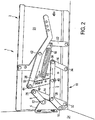
- FIGS. 2 to 5 basically show schematically a hinge that is closed between the representations of these four figures basically only by the respective position according to Figures 2 and 4 and opened according to Figures 3 and 5 on the one hand and the position of a spring 18 for use with a downwardly opening flap according to Figures 2 and 3 and for use with an upwardly opening flap in accordance with FIGS. 4 and 5 different.
- a spring 18 for use with a downwardly opening flap according to Figures 2 and 3 and for use with an upwardly opening flap in accordance with FIGS. 4 and 5 different.
- FIGS. 2 to 5 essentially the same reference numerals are used.
- the hinge of all FIGS. 2 to 5 referred to as hinge 1.
- the hinge 1 has, as a base element, a base plate 20 and a base strut 22 attached thereto.
- the base plate 20 is fixed to the body of a piece of furniture, which is in the FIG. 2 - and also the FIGS. 3 to 5 - but not detailed.
- the hinge 1, a fastening element 4 which is fixed to a flap 24 which in the FIGS. 2 to 5 only hinted at.
- the flap 24 is connected via the fastening element 4 with the first and second support arm, 6, 8.
- the connection is in each case made rotatably on the first and second flap pivot 10, 12.
- the first and second support arms 6, 8 are movably mounted on the base plate 20 via the first guide arm 14.
- the rotationally movable fastening takes place via a first holding pivot point 26 between the first holding arm 6 and the first guide arm 14, via a second holding pivot 28 between the second holding arm 28 and the first guiding arm 14 and via a first base pivot point 32 between the first guiding arm 14 and the base plate 20.
- the first support arm 6 is still rotatably connected via a second guide arm 16 with the base plate 20.
- These described as interconnected elements comprising the first and second arm 6, 8, the first and second guide arm fourteenth , 16 and the fastener 4 can be considered as a movement mechanism 36, as far as a firm attachment to the first and second base point 32, 34 takes place. Through this movement mechanism 36, a fixed path of movement during opening and closing of the flap 24 and the fastener 4 is achieved.
- an auxiliary guide arm 38 with a connecting arm 40 is now provided in addition to said movement mechanism 36.
- the auxiliary guide arm 38 is rotatably attached to the base brace 22 and thus to the base plate 20 at an auxiliary pivot 42.
- the connecting arm 40 connects the auxiliary guide arm 38 with the first support arm 6.
- the connections are made rotatable via a first connection pivot point 44 between the auxiliary guide arm 38 and connecting arm 40 and the second connection pivot point 46 between connecting arm 40 and first support arm.
- a spring 18 is secured to the base strut 22 and the connecting arm 40.
- the spring 18 in this case is under tension and pulls the connecting arm 40 in the direction of the spring force 48 to the base strut 22.
- the connecting arm which is basically supported on the auxiliary guide arm 38 at the first connection pivot 44, thus leading to a force 50 in the region of second connection pivot 46 basically acts in the closing direction on the first arm 6. The flap 24 is thereby held in the closed state.
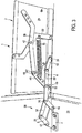
- FIG. 3 illustrated as opposed to FIG. 2 the hinge 1 in an open position.
- the flap 24 is in this case in a substantially horizontal position.
- the spring 18 is compared to the closed position according to FIG. 2 stretched something. Between the connecting arm 40 and the auxiliary guide arm 38 is an angle 52, which is significantly greater than 90 °, is about 140 °.
- the spring force 48 ' is compared to FIG. 2 Although increased due to the extension of the spring 18, due to the large angle 52 but only worse the force on the second connecting pivot 46 on the first arm 6 exercise and also the very bottle position of the first and second guide arm 14, 16 causes the spring force 48 'is unable to close the flap 24 against the force of gravity.
- the spring force 48 'or 48 also exerts a force on the auxiliary guide arm 38, namely, by the force acting on the connecting arm 40, which is supported on the auxiliary guide arm 38 in the region of the first connection pivot point 44 basically.
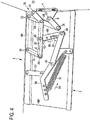
- FIG. 4 relates to a hinge for an upwardly opening flap 24.
- the hinge 1 is according to FIG. 4 according to the representation of FIG. 2 rotated by 180 °.
- the spring 18 in this case exerts a spring force 54 on the auxiliary guide arm 38.
- This tensile force 54 is basically converted via the auxiliary pivot point 42 to a thrust force 56 which acts on the connecting arm 40 at the first connection pivot point 44.
- This thrust force 56 is passed through the second connection pivot point 46 on the first arm 6 and leads to a force 58 in the closing direction of the support arm 6.
- the direction of this force 58 in the closing direction is both by the An-griffswinkel 62 of the connecting arm 40 on the first arm 6 and determined by the position of the two guide arms 14 and 16.
- a parallelogram 60 is indicated by dashed lines in FIG FIG. 4 located.
- This parallelogram 60 is defined by the first and second base fulcrums 32, 34 and the first and third support fulcrums 26, 30.
- the parallelogram 60 in the illustrated closed position of the flap 24, is slightly above a state of the motion mechanism 36 in which this parallelogram is taken 60 takes the special form of a rectangle.
- the invention makes use of this position of the parallelogram 60, so that the thrust force 56 leads to the force 58 in the closing direction. This is facilitated by the fact that an angle drawn between the connecting arm 40 and the first holding arm 6 as an attack angle 62 is greater than 90 °.
- the spring force 54 can ultimately be converted into a closing force.
- the hinges are in accordance with FIG. 2 and 4 In their construction agree or are identical, except for the arrangement of the spring 18th
- the flap 24, according to FIG. 4 opens up, basically alone by the weight in the closed position would remain.
- the illustrated mechanism leads to a state in which the flap 24 is tightened more firmly than by the weight alone in its closed position. As a result, for example, a Klappem can be prevented.
- FIG. 5 the flap 24 is now shown in its upwardly open position.
- the flap 24 is approximately horizontal and the weight force acting on it urges the flap 24 to close.
- the spring 18 now exerts a spring force 54 'on the auxiliary guide arm 38, which is redirected via the first connection pivot 44 in a thrust force 56', which leads at the second connection pivot point 46 to a force 64 on the first support arm 6 in the opening direction.
- the direction of the force depends both on the angle of attack 62 'between the connecting arm 40 and the first holding arm 6 and the position of the parallelogram 60'.
- the parallelogram 60 ' is like the parallelogram 60 according to FIG FIG. 4 defined and shown in dashed lines.
- the parallelogram 60 ' is designed comparatively flat, compare to the configuration of the parallelogram 60 according to FIG. 4 , For the weight force that acts on the flap 24 to Schlle ⁇ en, the position of the hinge is unfavorable.
- the flap 24 can thus ultimately be kept open by the spring force 54 'open.
- the position of the movement mechanism 36 and the wide open angle 52 ' are important for this purpose. Due to the wide open angle 52 'adjusts itself for the auxiliary guide arm 38 with the connecting arm 40 a toggle effect. If the angle 52 'at 180 °, the weight acting on the flap 24, the flap 24 could not close even at a spring force 54' of practically 0 Newton.
- the angle 52 'according to FIG. 5 has a value less than 180 °, so that closing is possible. However, the angle 52 'is so large that the spring 18 still leads to a fairly large force, in particular to such a large force 56', which counteracts the closing of the flap 24.
Landscapes
- Engineering & Computer Science (AREA)
- Mechanical Engineering (AREA)
- Hinges (AREA)
Claims (7)
- Charnière (1) pour la fixation pivotante d'un abattant (24) sur un caisson, d'un meuble ou un autre corps, pour la fermeture et l'ouverture d'une ouverture du caisson ou du corps, comprenant- un élément de base (20) pour la fixation de la charnière (1) sur le caisson ou le corps,- un élément de fixation (4) pour la fixation de la charnière (1) sur l'abattant (24),- une mécanique de déplacement pour guider l'élément de fixation sur une trajectoire, dans laquelle- la trajectoire est prédéfinie fixement par rapport à l'élément de base (20) par la configuration de la mécanique de déplacement (36) et- la mécanique de déplacement (36) est une charnière avec multiples points d'appui et présente un premier bras de retenue (6) relié mobile en rotation avec l'élément de fixation (4) à un premier point de rotation d'abattant (10)- un bras de guidage auxiliaire (38) fixé mobile en rotation au niveau de l'élément de base (20) à un point de rotation auxiliaire (42),- un bras de liaison (40) pour relier le bras de guidage auxiliaire (38) au premier bras de retenue (6), dans laquelle le bras de liaison (40)- est relié de manière rotative avec le bras de guidage auxiliaire (38) à un premier point de rotation de liaison (44) et- est relié de manière rotative avec le premier bras de retenue (6) à un deuxième point de rotation de liaison (46), et- un élément formant ressort (18) pour la mise à disposition d'une précontrainte pour maintenir l'abattant (24) dans un état fermé et/ou ouvert, dans laquelle l'élément formant ressort (18) exerce une force sur le bras de guidage auxiliaire (38),caractérisée en ce que la même charnière (1) est préparée en fonction de la position de l'élément formant ressort (18) pour l'utilisation avec un abattant (24) s'ouvrant vers le haut ou vers le bas conformément à l'affectation, dans laquelle l'élément formant ressort (18) est soit fixé avec un premier côté sur l'élément de base (20) et avec un deuxième côté pour l'abattant (24) s'ouvrant vers le bas sur le bras de liaison (40) soit fixé avec un premier côté sur l'élément de base (20) et avec un deuxième côté pour l'abattant (24) s'ouvrant vers le haut sur le bras de guidage auxiliaire (38).
- Charnière (1) selon la revendication 1, caractérisée en ce que le bras de guidage auxiliaire (38) s'étend du point de rotation auxiliaire (42)- vers un premier côté, et est relié de manière rotative au bras de liaison (40) au niveau du premier côté au premier point de rotation de liaison (44), et- vers un deuxième côté opposé au premier côté, dans laquelle ce deuxième côté du bras de guidage auxiliaire (38) est préparé pour être relié au deuxième côté de l'élément formant ressort (18) et/ou dans laquelle le deuxième côté du bras de guidage auxiliaire (38) est relié au deuxième côté de l'élément formant ressort (18).
- Charnière (1) selon l'une quelconque des revendications 1 et 2, caractérisée en ce que la charnière (1) est préparée pour maintenir l'abattant (24) dans une position ouverte et dans une position fermée lors de l'utilisation conforme à l'affectation.
- Charnière (1) selon la revendication 3, caractérisée en ce que l'élément formant ressort (18) est fixé sur le bras de guidage auxiliaire (38) et exerce une force sur le premier bras de retenue (6) par le biais du bras de guidage auxiliaire (38) et du bras de liaison (40), dans laquelle la force est dirigée, à l'état ouvert de l'abattant (24), dans une direction pour maintenir l'abattant (24) ouvert et, à l'état fermé, dans une direction pour maintenir l'abattant (24) fermé, dans laquelle la direction de la force dépend de préférence de la position du bras de liaison (40).
- Charnière (1) selon l'une quelconque des revendications précédentes, caractérisée en ce que la mécanique de déplacement (36) comprend- le premier bras de retenue (6),- un deuxième bras de retenue relié mobile en rotation avec l'élément de fixation (4) à un deuxième point de rotation d'abattant (12),- un premier bras de guidage (14), qui est relié mobile en rotation- avec l'élément de base (20) à un premier point de rotation de base (32),- avec le premier bras de retenue (6) à un premier point de rotation de retenue (26) et- avec le deuxième bras de retenue (8) à un deuxième point de rotation de retenue (28),- un deuxième bras de guidage (16), qui est relié mobile en rotation- avec l'élément de base (20) à un deuxième point de rotation de base (34) et- avec le premier bras de retenue (8) à un troisième point de rotation de retenue (34).
- Charnière (1) selon l'une quelconque des revendications précédentes, caractérisée en ce que- les premier et deuxième points de rotation de liaison (44, 46) définissent un tronçon de liaison,- le premier point de rotation de liaison (44) et le point de rotation auxiliaire (42) définissent un tronçon auxiliaire et- lors de l'utilisation conforme à l'affectation, le tronçon de liaison avec le tronçon auxiliaire- forment, à l'état fermé de l'abattant (24), un angle aigu, de préférence dans la plage de 30° à 85°, en particulier dans la plage de 45° à 80° et- forment, à l'état ouvert de l'abattant (24), un angle obtus, de préférence dans la plage de 120° à 175°, en particulier dans la plage de 135° à 170°.
- Meuble avec un caisson avec au moins un abattant (24), caractérisé en ce que l'abattant (24) est fixé de manière mobile sur le caisson au moyen d'au moins une, de préférence deux, charnière(s) (1) selon l'une quelconque des revendications précédentes.
Applications Claiming Priority (1)
| Application Number | Priority Date | Filing Date | Title |
|---|---|---|---|
| DE200920006480 DE202009006480U1 (de) | 2009-05-04 | 2009-05-04 | Mehrgelenksscharnier |
Publications (3)
| Publication Number | Publication Date |
|---|---|
| EP2248974A2 EP2248974A2 (fr) | 2010-11-10 |
| EP2248974A3 EP2248974A3 (fr) | 2013-07-24 |
| EP2248974B1 true EP2248974B1 (fr) | 2017-05-17 |
Family
ID=42751923
Family Applications (2)
| Application Number | Title | Priority Date | Filing Date |
|---|---|---|---|
| EP20100161811 Withdrawn EP2333210A2 (fr) | 2009-05-04 | 2010-05-04 | Charnière à plusieurs articulations |
| EP10075377.1A Active EP2248974B1 (fr) | 2009-05-04 | 2010-07-05 | Charnière avec multiple points d'appui |
Family Applications Before (1)
| Application Number | Title | Priority Date | Filing Date |
|---|---|---|---|
| EP20100161811 Withdrawn EP2333210A2 (fr) | 2009-05-04 | 2010-05-04 | Charnière à plusieurs articulations |
Country Status (3)
| Country | Link |
|---|---|
| EP (2) | EP2333210A2 (fr) |
| DE (1) | DE202009006480U1 (fr) |
| ES (1) | ES2633747T3 (fr) |
Families Citing this family (1)
| Publication number | Priority date | Publication date | Assignee | Title |
|---|---|---|---|---|
| DE202012009218U1 (de) | 2012-09-26 | 2013-01-25 | Versee Gmbh | Scharnier |
Family Cites Families (7)
| Publication number | Priority date | Publication date | Assignee | Title |
|---|---|---|---|---|
| US2120685A (en) * | 1936-07-18 | 1938-06-14 | Soss | Automatic latch concealed hinge |
| EP0361020A1 (fr) * | 1988-09-23 | 1990-04-04 | Techform Products Ltd. | Charnière à double mouvement pour capots de coffre |
| CH696274A5 (de) * | 1995-04-04 | 2007-03-15 | Usm Holding Ag | Vorrichtung zum schwenkbaren Halten einer Flügelklappe. |
| IT1304909B1 (it) * | 1998-10-13 | 2001-04-05 | Tgn S P A | Cerniera a scatto per il sostegno di elementi piastriformi dichiusura. |
| ITMO20050156A1 (it) * | 2005-06-21 | 2006-12-22 | Tgn Spa | Cerniera a scatto per il sostegno di un elemento di chiusura. |
| DE202005016375U1 (de) * | 2005-10-13 | 2005-12-22 | Hetal-Werke Franz Hettich Gmbh & Co. Kg | Beschlag zum schwenkbaren Befestigen einer Frontklappe an einem Möbelschrank |
| DE202007006689U1 (de) * | 2007-05-07 | 2008-09-18 | Hetal-Werke Franz Hettich Gmbh & Co. Kg | Antriebseinrichtung für einen Beschlag |
-
2009
- 2009-05-04 DE DE200920006480 patent/DE202009006480U1/de not_active Expired - Lifetime
-
2010
- 2010-05-04 EP EP20100161811 patent/EP2333210A2/fr not_active Withdrawn
- 2010-07-05 EP EP10075377.1A patent/EP2248974B1/fr active Active
- 2010-07-05 ES ES10075377.1T patent/ES2633747T3/es active Active
Non-Patent Citations (1)
| Title |
|---|
| None * |
Also Published As
| Publication number | Publication date |
|---|---|
| DE202009006480U1 (de) | 2010-09-23 |
| EP2333210A2 (fr) | 2011-06-15 |
| EP2248974A3 (fr) | 2013-07-24 |
| EP2248974A2 (fr) | 2010-11-10 |
| ES2633747T3 (es) | 2017-09-25 |
Similar Documents
| Publication | Publication Date | Title |
|---|---|---|
| EP3198097B1 (fr) | Charnière pour meubles | |
| EP1934423B1 (fr) | Ferrure pour abattant | |
| AT516784B1 (de) | Möbel | |
| EP3198096B1 (fr) | Charnière de meuble | |
| EP2467550A1 (fr) | Meuble à dispositif de bras de commande | |
| EP1785567A2 (fr) | Ferrure pour un volet de meuble | |
| DE3911396A1 (de) | Aufhaengung einer tuer an einer fahrzeugkarosserie | |
| DE202012009218U1 (de) | Scharnier | |
| DE202010015092U1 (de) | Möbelbeschlag und Möbel | |
| EP1999328B1 (fr) | Porte-clapet pour clapet de meuble | |
| EP1835107B1 (fr) | Support de volet pour un volet de meuble | |
| WO1999015749A1 (fr) | Ferrure pour montage pivotant d'un vantail de fenetre ou de porte | |
| EP2248974B1 (fr) | Charnière avec multiple points d'appui | |
| EP1589174A2 (fr) | Ferrure de portes pliantes | |
| DE102020207128B3 (de) | Scharnier mit integrierter Anschlagdämpfung | |
| EP3124729B1 (fr) | Élement de retenue pour le reglage d'un couvercle de meuble | |
| DE202008010012U1 (de) | Klappenhalter für eine Möbelklappe | |
| DE102017126368A1 (de) | Möbelplatte mit einem Klappenbeschlag und Möbelkorpus sowie Möbel mit einer derartigen Möbelplatte | |
| DE10335709A1 (de) | Scharnier zum gelenkigen Verbinden zweier Faltelemente einer Faltklappe oder Falttüre | |
| DE854015C (de) | Tueroffenhalter fuer Kraftfahrzeuge | |
| DE2443036A1 (de) | Ausstellvorrichtung | |
| DE202012000152U1 (de) | Beschlaganordnung | |
| EP3623558B1 (fr) | Ferrure de couvercle destinée à la fixation pivotante d'un couvercle à un corps de meuble | |
| DE2802177A1 (de) | Klappbarer wandtisch | |
| EP1837471A2 (fr) | Support de volet |
Legal Events
| Date | Code | Title | Description |
|---|---|---|---|
| PUAI | Public reference made under article 153(3) epc to a published international application that has entered the european phase |
Free format text: ORIGINAL CODE: 0009012 |
|
| 17P | Request for examination filed |
Effective date: 20100705 |
|
| AK | Designated contracting states |
Kind code of ref document: A2 Designated state(s): AL AT BE BG CH CY CZ DE DK EE ES FI FR GB GR HR HU IE IS IT LI LT LU LV MC MK MT NL NO PL PT RO SE SI SK SM TR |
|
| AX | Request for extension of the european patent |
Extension state: BA ME RS |
|
| PUAL | Search report despatched |
Free format text: ORIGINAL CODE: 0009013 |
|
| AK | Designated contracting states |
Kind code of ref document: A3 Designated state(s): AL AT BE BG CH CY CZ DE DK EE ES FI FR GB GR HR HU IE IS IT LI LT LU LV MC MK MT NL NO PL PT RO SE SI SK SM TR |
|
| AX | Request for extension of the european patent |
Extension state: BA ME RS |
|
| RIC1 | Information provided on ipc code assigned before grant |
Ipc: E05D 3/16 20060101AFI20130620BHEP Ipc: E05F 1/12 20060101ALI20130620BHEP |
|
| RIC1 | Information provided on ipc code assigned before grant |
Ipc: E05F 1/12 20060101ALI20150219BHEP Ipc: E05D 3/16 20060101AFI20150219BHEP |
|
| 17Q | First examination report despatched |
Effective date: 20150506 |
|
| GRAP | Despatch of communication of intention to grant a patent |
Free format text: ORIGINAL CODE: EPIDOSNIGR1 |
|
| INTG | Intention to grant announced |
Effective date: 20161123 |
|
| GRAS | Grant fee paid |
Free format text: ORIGINAL CODE: EPIDOSNIGR3 |
|
| GRAJ | Information related to disapproval of communication of intention to grant by the applicant or resumption of examination proceedings by the epo deleted |
Free format text: ORIGINAL CODE: EPIDOSDIGR1 |
|
| GRAL | Information related to payment of fee for publishing/printing deleted |
Free format text: ORIGINAL CODE: EPIDOSDIGR3 |
|
| GRAR | Information related to intention to grant a patent recorded |
Free format text: ORIGINAL CODE: EPIDOSNIGR71 |
|
| GRAA | (expected) grant |
Free format text: ORIGINAL CODE: 0009210 |
|
| INTC | Intention to grant announced (deleted) | ||
| AK | Designated contracting states |
Kind code of ref document: B1 Designated state(s): AL AT BE BG CH CY CZ DE DK EE ES FI FR GB GR HR HU IE IS IT LI LT LU LV MC MK MT NL NO PL PT RO SE SI SK SM TR |
|
| INTG | Intention to grant announced |
Effective date: 20170411 |
|
| REG | Reference to a national code |
Ref country code: GB Ref legal event code: FG4D Free format text: NOT ENGLISH |
|
| REG | Reference to a national code |
Ref country code: CH Ref legal event code: EP Ref country code: CH Ref legal event code: NV Representative=s name: E. BLUM AND CO. AG PATENT- UND MARKENANWAELTE , CH |
|
| REG | Reference to a national code |
Ref country code: IE Ref legal event code: FG4D Free format text: LANGUAGE OF EP DOCUMENT: GERMAN |
|
| REG | Reference to a national code |
Ref country code: AT Ref legal event code: REF Ref document number: 894629 Country of ref document: AT Kind code of ref document: T Effective date: 20170615 |
|
| REG | Reference to a national code |
Ref country code: DE Ref legal event code: R096 Ref document number: 502010013605 Country of ref document: DE |
|
| REG | Reference to a national code |
Ref country code: FR Ref legal event code: PLFP Year of fee payment: 8 |
|
| REG | Reference to a national code |
Ref country code: NL Ref legal event code: FP |
|
| REG | Reference to a national code |
Ref country code: ES Ref legal event code: FG2A Ref document number: 2633747 Country of ref document: ES Kind code of ref document: T3 Effective date: 20170925 |
|
| REG | Reference to a national code |
Ref country code: LT Ref legal event code: MG4D |
|
| PG25 | Lapsed in a contracting state [announced via postgrant information from national office to epo] |
Ref country code: NO Free format text: LAPSE BECAUSE OF FAILURE TO SUBMIT A TRANSLATION OF THE DESCRIPTION OR TO PAY THE FEE WITHIN THE PRESCRIBED TIME-LIMIT Effective date: 20170817 Ref country code: FI Free format text: LAPSE BECAUSE OF FAILURE TO SUBMIT A TRANSLATION OF THE DESCRIPTION OR TO PAY THE FEE WITHIN THE PRESCRIBED TIME-LIMIT Effective date: 20170517 Ref country code: HR Free format text: LAPSE BECAUSE OF FAILURE TO SUBMIT A TRANSLATION OF THE DESCRIPTION OR TO PAY THE FEE WITHIN THE PRESCRIBED TIME-LIMIT Effective date: 20170517 Ref country code: GR Free format text: LAPSE BECAUSE OF FAILURE TO SUBMIT A TRANSLATION OF THE DESCRIPTION OR TO PAY THE FEE WITHIN THE PRESCRIBED TIME-LIMIT Effective date: 20170818 Ref country code: LT Free format text: LAPSE BECAUSE OF FAILURE TO SUBMIT A TRANSLATION OF THE DESCRIPTION OR TO PAY THE FEE WITHIN THE PRESCRIBED TIME-LIMIT Effective date: 20170517 |
|
| PG25 | Lapsed in a contracting state [announced via postgrant information from national office to epo] |
Ref country code: PL Free format text: LAPSE BECAUSE OF FAILURE TO SUBMIT A TRANSLATION OF THE DESCRIPTION OR TO PAY THE FEE WITHIN THE PRESCRIBED TIME-LIMIT Effective date: 20170517 Ref country code: LV Free format text: LAPSE BECAUSE OF FAILURE TO SUBMIT A TRANSLATION OF THE DESCRIPTION OR TO PAY THE FEE WITHIN THE PRESCRIBED TIME-LIMIT Effective date: 20170517 Ref country code: IS Free format text: LAPSE BECAUSE OF FAILURE TO SUBMIT A TRANSLATION OF THE DESCRIPTION OR TO PAY THE FEE WITHIN THE PRESCRIBED TIME-LIMIT Effective date: 20170917 Ref country code: SE Free format text: LAPSE BECAUSE OF FAILURE TO SUBMIT A TRANSLATION OF THE DESCRIPTION OR TO PAY THE FEE WITHIN THE PRESCRIBED TIME-LIMIT Effective date: 20170517 Ref country code: BG Free format text: LAPSE BECAUSE OF FAILURE TO SUBMIT A TRANSLATION OF THE DESCRIPTION OR TO PAY THE FEE WITHIN THE PRESCRIBED TIME-LIMIT Effective date: 20170817 |
|
| PG25 | Lapsed in a contracting state [announced via postgrant information from national office to epo] |
Ref country code: EE Free format text: LAPSE BECAUSE OF FAILURE TO SUBMIT A TRANSLATION OF THE DESCRIPTION OR TO PAY THE FEE WITHIN THE PRESCRIBED TIME-LIMIT Effective date: 20170517 Ref country code: DK Free format text: LAPSE BECAUSE OF FAILURE TO SUBMIT A TRANSLATION OF THE DESCRIPTION OR TO PAY THE FEE WITHIN THE PRESCRIBED TIME-LIMIT Effective date: 20170517 Ref country code: CZ Free format text: LAPSE BECAUSE OF FAILURE TO SUBMIT A TRANSLATION OF THE DESCRIPTION OR TO PAY THE FEE WITHIN THE PRESCRIBED TIME-LIMIT Effective date: 20170517 Ref country code: RO Free format text: LAPSE BECAUSE OF FAILURE TO SUBMIT A TRANSLATION OF THE DESCRIPTION OR TO PAY THE FEE WITHIN THE PRESCRIBED TIME-LIMIT Effective date: 20170517 Ref country code: SK Free format text: LAPSE BECAUSE OF FAILURE TO SUBMIT A TRANSLATION OF THE DESCRIPTION OR TO PAY THE FEE WITHIN THE PRESCRIBED TIME-LIMIT Effective date: 20170517 |
|
| REG | Reference to a national code |
Ref country code: DE Ref legal event code: R097 Ref document number: 502010013605 Country of ref document: DE |
|
| PG25 | Lapsed in a contracting state [announced via postgrant information from national office to epo] |
Ref country code: SM Free format text: LAPSE BECAUSE OF FAILURE TO SUBMIT A TRANSLATION OF THE DESCRIPTION OR TO PAY THE FEE WITHIN THE PRESCRIBED TIME-LIMIT Effective date: 20170517 |
|
| PLBE | No opposition filed within time limit |
Free format text: ORIGINAL CODE: 0009261 |
|
| STAA | Information on the status of an ep patent application or granted ep patent |
Free format text: STATUS: NO OPPOSITION FILED WITHIN TIME LIMIT |
|
| REG | Reference to a national code |
Ref country code: IE Ref legal event code: MM4A |
|
| 26N | No opposition filed |
Effective date: 20180220 |
|
| PG25 | Lapsed in a contracting state [announced via postgrant information from national office to epo] |
Ref country code: IE Free format text: LAPSE BECAUSE OF NON-PAYMENT OF DUE FEES Effective date: 20170705 |
|
| PG25 | Lapsed in a contracting state [announced via postgrant information from national office to epo] |
Ref country code: SI Free format text: LAPSE BECAUSE OF FAILURE TO SUBMIT A TRANSLATION OF THE DESCRIPTION OR TO PAY THE FEE WITHIN THE PRESCRIBED TIME-LIMIT Effective date: 20170517 |
|
| REG | Reference to a national code |
Ref country code: FR Ref legal event code: PLFP Year of fee payment: 9 |
|
| PGFP | Annual fee paid to national office [announced via postgrant information from national office to epo] |
Ref country code: LU Payment date: 20180723 Year of fee payment: 9 |
|
| PG25 | Lapsed in a contracting state [announced via postgrant information from national office to epo] |
Ref country code: MT Free format text: LAPSE BECAUSE OF FAILURE TO SUBMIT A TRANSLATION OF THE DESCRIPTION OR TO PAY THE FEE WITHIN THE PRESCRIBED TIME-LIMIT Effective date: 20170517 |
|
| PGFP | Annual fee paid to national office [announced via postgrant information from national office to epo] |
Ref country code: MC Payment date: 20180731 Year of fee payment: 9 Ref country code: ES Payment date: 20180829 Year of fee payment: 9 Ref country code: NL Payment date: 20180723 Year of fee payment: 9 Ref country code: FR Payment date: 20180723 Year of fee payment: 9 Ref country code: IT Payment date: 20180720 Year of fee payment: 9 |
|
| PGFP | Annual fee paid to national office [announced via postgrant information from national office to epo] |
Ref country code: SE Payment date: 20180910 Year of fee payment: 9 |
|
| PG25 | Lapsed in a contracting state [announced via postgrant information from national office to epo] |
Ref country code: HU Free format text: LAPSE BECAUSE OF FAILURE TO SUBMIT A TRANSLATION OF THE DESCRIPTION OR TO PAY THE FEE WITHIN THE PRESCRIBED TIME-LIMIT; INVALID AB INITIO Effective date: 20100705 |
|
| PG25 | Lapsed in a contracting state [announced via postgrant information from national office to epo] |
Ref country code: CY Free format text: LAPSE BECAUSE OF NON-PAYMENT OF DUE FEES Effective date: 20170517 |
|
| PG25 | Lapsed in a contracting state [announced via postgrant information from national office to epo] |
Ref country code: MK Free format text: LAPSE BECAUSE OF FAILURE TO SUBMIT A TRANSLATION OF THE DESCRIPTION OR TO PAY THE FEE WITHIN THE PRESCRIBED TIME-LIMIT Effective date: 20170517 |
|
| PG25 | Lapsed in a contracting state [announced via postgrant information from national office to epo] |
Ref country code: MC Free format text: LAPSE BECAUSE OF NON-PAYMENT OF DUE FEES Effective date: 20190731 |
|
| REG | Reference to a national code |
Ref country code: AT Ref legal event code: MM01 Ref document number: 894629 Country of ref document: AT Kind code of ref document: T Effective date: 20190705 |
|
| PG25 | Lapsed in a contracting state [announced via postgrant information from national office to epo] |
Ref country code: TR Free format text: LAPSE BECAUSE OF FAILURE TO SUBMIT A TRANSLATION OF THE DESCRIPTION OR TO PAY THE FEE WITHIN THE PRESCRIBED TIME-LIMIT Effective date: 20170517 |
|
| REG | Reference to a national code |
Ref country code: BE Ref legal event code: MM Effective date: 20190731 |
|
| PG25 | Lapsed in a contracting state [announced via postgrant information from national office to epo] |
Ref country code: NL Free format text: LAPSE BECAUSE OF NON-PAYMENT OF DUE FEES Effective date: 20190801 Ref country code: AT Free format text: LAPSE BECAUSE OF NON-PAYMENT OF DUE FEES Effective date: 20190705 |
|
| REG | Reference to a national code |
Ref country code: NL Ref legal event code: MM Effective date: 20190801 |
|
| PG25 | Lapsed in a contracting state [announced via postgrant information from national office to epo] |
Ref country code: BE Free format text: LAPSE BECAUSE OF NON-PAYMENT OF DUE FEES Effective date: 20190731 Ref country code: PT Free format text: LAPSE BECAUSE OF FAILURE TO SUBMIT A TRANSLATION OF THE DESCRIPTION OR TO PAY THE FEE WITHIN THE PRESCRIBED TIME-LIMIT Effective date: 20170517 Ref country code: LU Free format text: LAPSE BECAUSE OF NON-PAYMENT OF DUE FEES Effective date: 20190705 |
|
| PG25 | Lapsed in a contracting state [announced via postgrant information from national office to epo] |
Ref country code: FR Free format text: LAPSE BECAUSE OF NON-PAYMENT OF DUE FEES Effective date: 20190731 |
|
| PG25 | Lapsed in a contracting state [announced via postgrant information from national office to epo] |
Ref country code: AL Free format text: LAPSE BECAUSE OF FAILURE TO SUBMIT A TRANSLATION OF THE DESCRIPTION OR TO PAY THE FEE WITHIN THE PRESCRIBED TIME-LIMIT Effective date: 20170517 |
|
| PG25 | Lapsed in a contracting state [announced via postgrant information from national office to epo] |
Ref country code: IT Free format text: LAPSE BECAUSE OF NON-PAYMENT OF DUE FEES Effective date: 20190705 |
|
| REG | Reference to a national code |
Ref country code: ES Ref legal event code: FD2A Effective date: 20201126 |
|
| PG25 | Lapsed in a contracting state [announced via postgrant information from national office to epo] |
Ref country code: ES Free format text: LAPSE BECAUSE OF NON-PAYMENT OF DUE FEES Effective date: 20190706 |
|
| PGFP | Annual fee paid to national office [announced via postgrant information from national office to epo] |
Ref country code: GB Payment date: 20221006 Year of fee payment: 13 |
|
| PGFP | Annual fee paid to national office [announced via postgrant information from national office to epo] |
Ref country code: CH Payment date: 20221027 Year of fee payment: 13 |
|
| PGFP | Annual fee paid to national office [announced via postgrant information from national office to epo] |
Ref country code: DE Payment date: 20230808 Year of fee payment: 14 |
|
| REG | Reference to a national code |
Ref country code: CH Ref legal event code: PL |
|
| GBPC | Gb: european patent ceased through non-payment of renewal fee |
Effective date: 20230705 |
|
| PG25 | Lapsed in a contracting state [announced via postgrant information from national office to epo] |
Ref country code: CH Free format text: LAPSE BECAUSE OF NON-PAYMENT OF DUE FEES Effective date: 20230731 Ref country code: GB Free format text: LAPSE BECAUSE OF NON-PAYMENT OF DUE FEES Effective date: 20230705 |