EP2248974B1 - Multiple fulcrum hinge - Google Patents
Multiple fulcrum hinge Download PDFInfo
- Publication number
- EP2248974B1 EP2248974B1 EP10075377.1A EP10075377A EP2248974B1 EP 2248974 B1 EP2248974 B1 EP 2248974B1 EP 10075377 A EP10075377 A EP 10075377A EP 2248974 B1 EP2248974 B1 EP 2248974B1
- Authority
- EP
- European Patent Office
- Prior art keywords
- flap
- arm
- hinge
- pivot point
- guide arm
- Prior art date
- Legal status (The legal status is an assumption and is not a legal conclusion. Google has not performed a legal analysis and makes no representation as to the accuracy of the status listed.)
- Active
Links
- 230000001154 acute effect Effects 0.000 claims description 3
- 230000005484 gravity Effects 0.000 description 5
- 230000000694 effects Effects 0.000 description 3
- 238000010276 construction Methods 0.000 description 2
- 238000005192 partition Methods 0.000 description 2
- 230000001419 dependent effect Effects 0.000 description 1
- 230000002349 favourable effect Effects 0.000 description 1
- 210000000629 knee joint Anatomy 0.000 description 1
- 230000014759 maintenance of location Effects 0.000 description 1
- 230000000717 retained effect Effects 0.000 description 1
Images


Classifications
-
- E—FIXED CONSTRUCTIONS
- E05—LOCKS; KEYS; WINDOW OR DOOR FITTINGS; SAFES
- E05D—HINGES OR SUSPENSION DEVICES FOR DOORS, WINDOWS OR WINGS
- E05D3/00—Hinges with pins
- E05D3/06—Hinges with pins with two or more pins
- E05D3/16—Hinges with pins with two or more pins with seven parallel pins and four arms
-
- E—FIXED CONSTRUCTIONS
- E05—LOCKS; KEYS; WINDOW OR DOOR FITTINGS; SAFES
- E05F—DEVICES FOR MOVING WINGS INTO OPEN OR CLOSED POSITION; CHECKS FOR WINGS; WING FITTINGS NOT OTHERWISE PROVIDED FOR, CONCERNED WITH THE FUNCTIONING OF THE WING
- E05F1/00—Closers or openers for wings, not otherwise provided for in this subclass
- E05F1/08—Closers or openers for wings, not otherwise provided for in this subclass spring-actuated, e.g. for horizontally sliding wings
- E05F1/10—Closers or openers for wings, not otherwise provided for in this subclass spring-actuated, e.g. for horizontally sliding wings for swinging wings, e.g. counterbalance
- E05F1/12—Mechanisms in the shape of hinges or pivots, operated by springs
- E05F1/1246—Mechanisms in the shape of hinges or pivots, operated by springs with a coil spring perpendicular to the pivot axis
- E05F1/1269—Mechanisms in the shape of hinges or pivots, operated by springs with a coil spring perpendicular to the pivot axis with a traction spring
- E05F1/1276—Mechanisms in the shape of hinges or pivots, operated by springs with a coil spring perpendicular to the pivot axis with a traction spring for counterbalancing
-
- E—FIXED CONSTRUCTIONS
- E05—LOCKS; KEYS; WINDOW OR DOOR FITTINGS; SAFES
- E05Y—INDEXING SCHEME RELATING TO HINGES OR OTHER SUSPENSION DEVICES FOR DOORS, WINDOWS OR WINGS AND DEVICES FOR MOVING WINGS INTO OPEN OR CLOSED POSITION, CHECKS FOR WINGS AND WING FITTINGS NOT OTHERWISE PROVIDED FOR, CONCERNED WITH THE FUNCTIONING OF THE WING
- E05Y2600/00—Mounting or coupling arrangements for elements provided for in this subclass
- E05Y2600/10—Adjustable or movable
- E05Y2600/30—Adjustable or movable characterised by the type of motion
- E05Y2600/33—Stepwise motion
-
- E—FIXED CONSTRUCTIONS
- E05—LOCKS; KEYS; WINDOW OR DOOR FITTINGS; SAFES
- E05Y—INDEXING SCHEME RELATING TO HINGES OR OTHER SUSPENSION DEVICES FOR DOORS, WINDOWS OR WINGS AND DEVICES FOR MOVING WINGS INTO OPEN OR CLOSED POSITION, CHECKS FOR WINGS AND WING FITTINGS NOT OTHERWISE PROVIDED FOR, CONCERNED WITH THE FUNCTIONING OF THE WING
- E05Y2600/00—Mounting or coupling arrangements for elements provided for in this subclass
- E05Y2600/40—Mounting location; Visibility of the elements
- E05Y2600/458—Mounting location; Visibility of the elements in or on a transmission member
-
- E—FIXED CONSTRUCTIONS
- E05—LOCKS; KEYS; WINDOW OR DOOR FITTINGS; SAFES
- E05Y—INDEXING SCHEME RELATING TO HINGES OR OTHER SUSPENSION DEVICES FOR DOORS, WINDOWS OR WINGS AND DEVICES FOR MOVING WINGS INTO OPEN OR CLOSED POSITION, CHECKS FOR WINGS AND WING FITTINGS NOT OTHERWISE PROVIDED FOR, CONCERNED WITH THE FUNCTIONING OF THE WING
- E05Y2800/00—Details, accessories and auxiliary operations not otherwise provided for
- E05Y2800/15—Applicability
- E05Y2800/17—Universally applicable
- E05Y2800/172—Universally applicable on different wing or frame locations
-
- E—FIXED CONSTRUCTIONS
- E05—LOCKS; KEYS; WINDOW OR DOOR FITTINGS; SAFES
- E05Y—INDEXING SCHEME RELATING TO HINGES OR OTHER SUSPENSION DEVICES FOR DOORS, WINDOWS OR WINGS AND DEVICES FOR MOVING WINGS INTO OPEN OR CLOSED POSITION, CHECKS FOR WINGS AND WING FITTINGS NOT OTHERWISE PROVIDED FOR, CONCERNED WITH THE FUNCTIONING OF THE WING
- E05Y2800/00—Details, accessories and auxiliary operations not otherwise provided for
- E05Y2800/20—Combinations of elements
- E05Y2800/21—Combinations of elements of identical elements, e.g. of identical compression springs
-
- E—FIXED CONSTRUCTIONS
- E05—LOCKS; KEYS; WINDOW OR DOOR FITTINGS; SAFES
- E05Y—INDEXING SCHEME RELATING TO HINGES OR OTHER SUSPENSION DEVICES FOR DOORS, WINDOWS OR WINGS AND DEVICES FOR MOVING WINGS INTO OPEN OR CLOSED POSITION, CHECKS FOR WINGS AND WING FITTINGS NOT OTHERWISE PROVIDED FOR, CONCERNED WITH THE FUNCTIONING OF THE WING
- E05Y2800/00—Details, accessories and auxiliary operations not otherwise provided for
- E05Y2800/20—Combinations of elements
- E05Y2800/22—Combinations of elements of not identical elements of the same category, e.g. combinations of not identical springs
-
- E—FIXED CONSTRUCTIONS
- E05—LOCKS; KEYS; WINDOW OR DOOR FITTINGS; SAFES
- E05Y—INDEXING SCHEME RELATING TO HINGES OR OTHER SUSPENSION DEVICES FOR DOORS, WINDOWS OR WINGS AND DEVICES FOR MOVING WINGS INTO OPEN OR CLOSED POSITION, CHECKS FOR WINGS AND WING FITTINGS NOT OTHERWISE PROVIDED FOR, CONCERNED WITH THE FUNCTIONING OF THE WING
- E05Y2800/00—Details, accessories and auxiliary operations not otherwise provided for
- E05Y2800/26—Form, shape
- E05Y2800/292—Form, shape having apertures
-
- E—FIXED CONSTRUCTIONS
- E05—LOCKS; KEYS; WINDOW OR DOOR FITTINGS; SAFES
- E05Y—INDEXING SCHEME RELATING TO HINGES OR OTHER SUSPENSION DEVICES FOR DOORS, WINDOWS OR WINGS AND DEVICES FOR MOVING WINGS INTO OPEN OR CLOSED POSITION, CHECKS FOR WINGS AND WING FITTINGS NOT OTHERWISE PROVIDED FOR, CONCERNED WITH THE FUNCTIONING OF THE WING
- E05Y2900/00—Application of doors, windows, wings or fittings thereof
- E05Y2900/20—Application of doors, windows, wings or fittings thereof for furnitures, e.g. cabinets
Definitions
- the present invention relates to a hinge for pivotally attaching a flap to a body of a piece of furniture or other body for closing and opening an opening of the body.
- the invention further relates to a piece of furniture equipped with a multi-joint hinge.
- Multi-hinge jingles are well known. They are used in particular for doors or flaps of a piece of furniture in order to pivotably guide this door or flap so that a user can move the door or flap from an open to a closed position or vice versa.
- a simple hinge which is commonly used in room or front doors, for example, a multi-link hinge can create a more complex movement.
- the door or flap is thus not only hinged to a pivoting edge on the piece of furniture, but rather can move freely in all edges of the opening.
- the Mehrgefenksscharnier can optionally with the help of a corresponding Additional mechanics have the task to close the relevant flap and / or door in a closed state and in an open state - taking into account the gravity - keep open.
- Multi-joint hinges are thus often used for flaps that open and / or close at the top and / or at the top, that is to say essentially have a horizontal pivot axis.
- the term "flap" also includes elements such as doors.
- a disadvantage of known Mehrgelenksscharnieren is basically their complex structure.
- attaching a mechanism to open and / or close the respective flap is complicated and often depends on the very specific conditions of the flap, in particular Size and weight of the same.
- the hinge must be selected depending on whether a flap opens downwards or upwards. In a downwardly opening flap, gravity aids in stopping, whereas gravity on an upwardly opening flap counteracts stopping.
- a hinge according to claim 1 is proposed. Such has a base member for fixing to the furniture or the like, and a fixing member for fixing to the flap or the like.
- the hinge has a movement mechanism for guiding the fastener and thus when used properly for guiding the flap on a movement path.
- the trajectory is fixed with respect to the base element and thus when installed as intended with respect to the piece of furniture.
- the movement mechanism can basically be designed in different ways, but at least one holding arm is provided.
- This support arm is thus part of the movement mechanism and rotatably connected to the fastener and thus intended with the flap at a flap pivot.
- the first support arm is connected to the fastening element and as part of the movement mechanism with the base element, that this first support arm relative to the base member only on a fixed predetermined Bewebungsbahn can move.
- the first support arm is guided so that it maintains its orientation when moving on its predetermined path of movement.
- the first support arm thus has only one degree of freedom and the only possibility of movement of this support arm depends on the movement of the fastener and thus intended from the movement of the flap.
- a spring element for providing a bias for holding the flap in a closed and / or open state.
- the spring element in particular a spring
- the spring should be arranged on the hinge so that when used as intended a flap can be kept in an open state, in particular in a horizontal position, when the closed position is a vertical position.
- This can also mean, in the case of downwardly opening flaps, that the spring can not close a flap open against the force of gravity due to its force and arrangement. In this case, the weight retained the flap without the spring prevents this.
- it should also be taken into account in general how many hinges are used per flap. In many cases, two hinges are likely.
- an auxiliary guide arm rotatably mounted on the base member is provided, which is rotatably mounted about an auxiliary pivot point.
- a connecting arm is provided, which connects the auxiliary guide arm with the first support arm.
- the connecting arm is rotatably mounted both on an auxiliary guide arm, namely in the region of a first connecting pivot point, and on the first holding arm, there at a second connecting pivot point.
- the auxiliary guide arm can thus exert a force on the first holding arm by means of the connecting arm, if a force is introduced into the auxiliary guide arm.
- a movement of the first holding arm on a predetermined path of movement via the connecting arm also leads to a substantially predetermined movement of the auxiliary guide arm and also of the connecting arm.
- the described rotational movements or rotatable attachments are related to a rotation axis.
- Ball joints that allow greater freedom of movement than one Allow rotation axis are not provided in principle.
- described arms such as the support arm or the connecting arm, in principle also assume a physical configuration that differs from that of an arm.
- the connecting arm could be designed as a straight strut or as a surface element, angle or even voluminous body for connecting the first and second connection pivot, if this is reasonable and feasible due to the given space.
- the spring element exerts its power - directly or indirectly - on the auxiliary arm. This can be achieved according to the invention that the force acting ultimately on the fastener and intended on the flap, exerting its force depending on the position of the connecting arm and / or the position of the auxiliary guide arm.
- the spring element is fastened with a first side to the base element and with its second side either on the auxiliary guide arm or on the connecting arm.
- the spring element in particular the spring is designed as a tension spring.
- the spring element thus produces a tensile stress between the base element and the auxiliary guide arm or the base element and the connecting arm.
- the auxiliary guide arm extends from the auxiliary fulcrum in two substantially opposite directions, namely, to a first side, wherein the auxiliary guide arm is rotatably connected to the connecting arm in the region of this first side at the connecting pivot point, and to a second side, wherein the auxiliary guide arm in FIG Area of the second side, which is the first side substantially facing away, is prepared to be connected to the second side of the spring element. It may be advantageous to provide such a second side of the auxiliary guide arm without this side actually being connected to the second side of the spring element.
- the spring element is connected to this second side of the auxiliary guide arm and applies a force between the base element and this second side of the auxiliary guide arm.
- the invention proposes that the hinge be prepared to be used, depending on the position of the spring element, for use with an intended upwardly or downwardly opening flap. It is advantageous if the hinge is prepared to keep the flap in an open, in particular horizontal, and in a closed, in particular vertical position when used as intended. Due to the weight force acting strongly on the flap, especially in the open, horizontal state, the requirements for the hinge for holding the flap are very different, depending on whether the flap opens upwards or downwards.
- a hinge of one embodiment is characterized in that its use as a hinge for an upwardly or downwardly opening flap is determined by the position of the spring element.
- One and the same hinge can thus be changed by converting the spring element from a hinge for a downwardly opening flap to a hinge for an upwardly opening flap.
- the hinge is dimensioned so that in both cases the same spring element can be used.
- the hinge is characterized in that the spring element is attached to the auxiliary guide arm and exerts a force on the first holding arm via the auxiliary guide arm and the connecting arm, wherein the force in the open Condition of the flap is directed in a direction to keep open the flap and is directed in the closed state in a direction to keep the flap closed, wherein the direction of force preferably depends on the position of the connecting arm.
- the spring member is attached to the auxiliary guide arm so as to exert a force thereon.
- This force is further transmitted via the connecting arm on the first arm.
- the said force thus either supports the opening or the closing of the flap or the holding open or keeping closed the flap.
- This can be achieved in particular by the position of the connecting arm relative to the holding arm.
- the position of the connecting arm relative to the holding arm By the movement of the flap and thus the movement mechanism including the first support arm, the position of the connecting arm relative to the support arm and thus the direction of force exerted by the auxiliary guide arm on the connecting arm on the support arm.
- a force is possibly transmitted indirectly. This can also be done by the type of movement mechanics, in particular depend on how the first arm is guided.
- the hinge is thus adapted to assume a state of reversal of the force acting on the fastener and thus the flap between fully open position and fully closed position.
- a hinge of another embodiment is characterized in that the movement mechanism comprises: the first support arm, a second pivotally connected to a second flap pivot pivotally connected to the mounting arm support arm, a first guide arm which is rotatably connected to the base member at a first base pivot point with the first support arm at a first support pivot and the second support arm at a second support pivot, a second guide arm rotatably connected to the base member at a second base pivot and the first support arm at a third support pivot.
- the movement mechanism thus essentially has a first and a second retaining arm and a first and a second guide arm.
- both retaining arms are arranged parallel to one another, at least in the region from the first guide arm to the fastening element.
- the two guide arms are also preferably formed parallel to each other. This ensures that the two retaining arms remain partially formed while moving parallel to each other. This is achieved in particular by the fact that the distance between the two flap pivot points and the two holding fulcrums is the same.
- the first and second holding fulcrum and the first and second flap fulcrum mark a parallelogram.
- the first and second base fulcrum and the first and third fulcrums also signify a parallelogram. When this parallelogram attached to the base member assumes the shape of a rectangle due to its movement, it is at a turning point.
- the hinge is formed so that the described parallelogram of the first and second base fulcrum and the first and third holding fulcrum assumes the special shape of a rectangle in a position of the hinge between its intended fully opened and fully closed condition. It is favorable when the connecting arm engages between - in particular centrally between - the first and third holding fulcrum.
- a hinge is proposed, characterized in that the first and second connection fulcrum define a connection path, the first connection fulcrum and the auxiliary fulcrum define an auxiliary path and, when used as intended, the connection path with the auxiliary section in the closed state of the flap an acute Form angles, preferably in the range of 30 ° to 85 °, in particular in the range of 45 ° to 80 ° and in the open state of the flap form an obtuse angle, preferably in the range of 120 ° to 175 °, in particular in the range of 135 ° 170 °.
- an acute angle is proposed as an angle ⁇ 90 ° in the intended closed state of the door, whereby a force effect of the connecting arm on the first holding arm is achieved in a closing direction of the flap or favors, thereby holding the flap in a closed state.
- an obtuse angle ie an angle> 90 ° and ⁇ 180 ° is proposed.
- a so-called toggle effect occurs, according to which the first connection pivot point is for the knee joint and an angle of 180 ° would correspond to a complete extension.
- Such a full extension can thus hold the flap without significant force by the spring, if the direction of force of the connector points in the opening direction. Since in the case of a 180 ° angle, the flap would not be closed by a user, a slightly smaller angle than 180 ° is proposed.
- the movements referred to in this application basically refer to movement in a plane.
- a Mehrgelenksscharnier z. B. be arranged on the edge of a cabinet wall or cabinet partition wall - with or without fairing - and the movements, in particular the movements of the movement mechanism in this case extend in said wall or partition or in a plane parallel thereto.
- most or all pivot axes of the hinge, which are each provided at a pivot point, are formed parallel to each other.
- a piece of furniture which has a body with at least one flap.
- the flap is movably attached to the body with at least one, preferably two hinges according to the invention.
- a flap has a movement path of about 90 °, namely from a normal vertical closed position to a normal horizontal opening position.
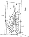
- FIG. 1 shows a hinge 101 according to the prior art.
- the hinge 101 has a base member 102 for attachment to the body of a cabinet, and a fastener 104 for securing a flap to move relative to the body.
- the illustrated hinge 101 is for a downwardly opening flap and the fastener 104 is to be secured in a lower portion of the flap.
- the hinge 101 has first and second support arms 106 and 108 which are rotatably mounted to the fastener 104 in first and second flap pivots 110 and 112 so as to maintain the flap on a predetermined path of travel via the fastener 104.
- the support arms 106 and 108 are in turn rotatably mounted to the base member 102 by means of first and second guide arms.
- the spring 118 which is secured between the first support arm 106 and the base member 102 with a bias, stretched and counteracted said opening movement.
- a flap can be held in a closed position by the spring 118 and the spring 118 also facilitates the closing movement.
- This hinge 101 is unsuitable for use with an upwardly opening flap which is to be stopped by the hinge in the opened state. It would either have to choose a different hinge, or an additional mechanism to achieve the retention of an upwardly opening flap.
- FIGS. 2 to 5 basically show schematically a hinge that is closed between the representations of these four figures basically only by the respective position according to Figures 2 and 4 and opened according to Figures 3 and 5 on the one hand and the position of a spring 18 for use with a downwardly opening flap according to Figures 2 and 3 and for use with an upwardly opening flap in accordance with FIGS. 4 and 5 different.
- a spring 18 for use with a downwardly opening flap according to Figures 2 and 3 and for use with an upwardly opening flap in accordance with FIGS. 4 and 5 different.
- FIGS. 2 to 5 essentially the same reference numerals are used.
- the hinge of all FIGS. 2 to 5 referred to as hinge 1.
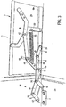
- the hinge 1 has, as a base element, a base plate 20 and a base strut 22 attached thereto.
- the base plate 20 is fixed to the body of a piece of furniture, which is in the FIG. 2 - and also the FIGS. 3 to 5 - but not detailed.
- the hinge 1, a fastening element 4 which is fixed to a flap 24 which in the FIGS. 2 to 5 only hinted at.
- the flap 24 is connected via the fastening element 4 with the first and second support arm, 6, 8.
- the connection is in each case made rotatably on the first and second flap pivot 10, 12.
- the first and second support arms 6, 8 are movably mounted on the base plate 20 via the first guide arm 14.
- the rotationally movable fastening takes place via a first holding pivot point 26 between the first holding arm 6 and the first guide arm 14, via a second holding pivot 28 between the second holding arm 28 and the first guiding arm 14 and via a first base pivot point 32 between the first guiding arm 14 and the base plate 20.
- the first support arm 6 is still rotatably connected via a second guide arm 16 with the base plate 20.
- These described as interconnected elements comprising the first and second arm 6, 8, the first and second guide arm fourteenth , 16 and the fastener 4 can be considered as a movement mechanism 36, as far as a firm attachment to the first and second base point 32, 34 takes place. Through this movement mechanism 36, a fixed path of movement during opening and closing of the flap 24 and the fastener 4 is achieved.
- an auxiliary guide arm 38 with a connecting arm 40 is now provided in addition to said movement mechanism 36.
- the auxiliary guide arm 38 is rotatably attached to the base brace 22 and thus to the base plate 20 at an auxiliary pivot 42.
- the connecting arm 40 connects the auxiliary guide arm 38 with the first support arm 6.
- the connections are made rotatable via a first connection pivot point 44 between the auxiliary guide arm 38 and connecting arm 40 and the second connection pivot point 46 between connecting arm 40 and first support arm.
- a spring 18 is secured to the base strut 22 and the connecting arm 40.
- the spring 18 in this case is under tension and pulls the connecting arm 40 in the direction of the spring force 48 to the base strut 22.
- the connecting arm which is basically supported on the auxiliary guide arm 38 at the first connection pivot 44, thus leading to a force 50 in the region of second connection pivot 46 basically acts in the closing direction on the first arm 6. The flap 24 is thereby held in the closed state.
- FIG. 3 illustrated as opposed to FIG. 2 the hinge 1 in an open position.
- the flap 24 is in this case in a substantially horizontal position.
- the spring 18 is compared to the closed position according to FIG. 2 stretched something. Between the connecting arm 40 and the auxiliary guide arm 38 is an angle 52, which is significantly greater than 90 °, is about 140 °.
- the spring force 48 ' is compared to FIG. 2 Although increased due to the extension of the spring 18, due to the large angle 52 but only worse the force on the second connecting pivot 46 on the first arm 6 exercise and also the very bottle position of the first and second guide arm 14, 16 causes the spring force 48 'is unable to close the flap 24 against the force of gravity.
- the spring force 48 'or 48 also exerts a force on the auxiliary guide arm 38, namely, by the force acting on the connecting arm 40, which is supported on the auxiliary guide arm 38 in the region of the first connection pivot point 44 basically.
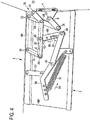
- FIG. 4 relates to a hinge for an upwardly opening flap 24.
- the hinge 1 is according to FIG. 4 according to the representation of FIG. 2 rotated by 180 °.
- the spring 18 in this case exerts a spring force 54 on the auxiliary guide arm 38.
- This tensile force 54 is basically converted via the auxiliary pivot point 42 to a thrust force 56 which acts on the connecting arm 40 at the first connection pivot point 44.
- This thrust force 56 is passed through the second connection pivot point 46 on the first arm 6 and leads to a force 58 in the closing direction of the support arm 6.
- the direction of this force 58 in the closing direction is both by the An-griffswinkel 62 of the connecting arm 40 on the first arm 6 and determined by the position of the two guide arms 14 and 16.
- a parallelogram 60 is indicated by dashed lines in FIG FIG. 4 located.
- This parallelogram 60 is defined by the first and second base fulcrums 32, 34 and the first and third support fulcrums 26, 30.
- the parallelogram 60 in the illustrated closed position of the flap 24, is slightly above a state of the motion mechanism 36 in which this parallelogram is taken 60 takes the special form of a rectangle.
- the invention makes use of this position of the parallelogram 60, so that the thrust force 56 leads to the force 58 in the closing direction. This is facilitated by the fact that an angle drawn between the connecting arm 40 and the first holding arm 6 as an attack angle 62 is greater than 90 °.
- the spring force 54 can ultimately be converted into a closing force.
- the hinges are in accordance with FIG. 2 and 4 In their construction agree or are identical, except for the arrangement of the spring 18th
- the flap 24, according to FIG. 4 opens up, basically alone by the weight in the closed position would remain.
- the illustrated mechanism leads to a state in which the flap 24 is tightened more firmly than by the weight alone in its closed position. As a result, for example, a Klappem can be prevented.
- FIG. 5 the flap 24 is now shown in its upwardly open position.
- the flap 24 is approximately horizontal and the weight force acting on it urges the flap 24 to close.
- the spring 18 now exerts a spring force 54 'on the auxiliary guide arm 38, which is redirected via the first connection pivot 44 in a thrust force 56', which leads at the second connection pivot point 46 to a force 64 on the first support arm 6 in the opening direction.
- the direction of the force depends both on the angle of attack 62 'between the connecting arm 40 and the first holding arm 6 and the position of the parallelogram 60'.
- the parallelogram 60 ' is like the parallelogram 60 according to FIG FIG. 4 defined and shown in dashed lines.
- the parallelogram 60 ' is designed comparatively flat, compare to the configuration of the parallelogram 60 according to FIG. 4 , For the weight force that acts on the flap 24 to Schlle ⁇ en, the position of the hinge is unfavorable.
- the flap 24 can thus ultimately be kept open by the spring force 54 'open.
- the position of the movement mechanism 36 and the wide open angle 52 ' are important for this purpose. Due to the wide open angle 52 'adjusts itself for the auxiliary guide arm 38 with the connecting arm 40 a toggle effect. If the angle 52 'at 180 °, the weight acting on the flap 24, the flap 24 could not close even at a spring force 54' of practically 0 Newton.
- the angle 52 'according to FIG. 5 has a value less than 180 °, so that closing is possible. However, the angle 52 'is so large that the spring 18 still leads to a fairly large force, in particular to such a large force 56', which counteracts the closing of the flap 24.
Description
Die vorliegende Erfindung betrifft ein Scharnier zum schwenkbaren Befestigen einer Klappe an einem Korpus eines Möbelstückes oder anderem Körper zum Verschließen und Öffnen einer Öffnung des Korpus bzw. Körpers, Weiterhin betrifft die Erfindung ein mit einem Mehrgelenksscharnier ausgestattetes Möbelstück.The present invention relates to a hinge for pivotally attaching a flap to a body of a piece of furniture or other body for closing and opening an opening of the body. The invention further relates to a piece of furniture equipped with a multi-joint hinge.
Mehrgelenksschamiere sind allgemein bekannt. Sie werden insbesondere für Türen oder Klappen eines Möbelstückes verwendet, um diese Tür oder Klappe schwenkbar zu führen, damit ein Benutzer die Tür oder Klappe aus einer geöffneten in eine geschlossene Position oder umgekehrt bewegen kann. Gegenüber einem einfachen Scharnier, das beispielsweise bei Zimmer- oder Haustüren üblicherweise verwendet wird, kann ein Mehrgelenksscharnier eine komplexere Bewegung schaffen. Die Tür oder Klappe wird somit nicht nur an einer Drehkante an dem Möbelstück angelenkt, sondern kann sich vielmehr in sämtlichen Kanten frei von der Öffnung bewegen. Zudem kann dem Mehrgefenksscharnier gegebenenfalls unter Zuhilfenahme einer entsprechenden Zusatzmechanik die Aufgabe zukommen, die betreffende Klappe und/oder Tür in einem geschlossenen Zustand geschlossen und in einem geöffneten Zustand - unter Berücksichtigung der Schwerkraft - offenzuhalten. Mehrgelenksscharniere werden somit häufig auch für Klappen eingesetzt, die nach unten und/oder oben öffnen bzw. schließen, also im Wesentlichen eine waagerechte Schwenkachse aufweisen. Nachfolgend beinhaltet der Begriff "Klappe" auch Elemente wie Türen.Multi-hinge jingles are well known. They are used in particular for doors or flaps of a piece of furniture in order to pivotably guide this door or flap so that a user can move the door or flap from an open to a closed position or vice versa. Compared with a simple hinge, which is commonly used in room or front doors, for example, a multi-link hinge can create a more complex movement. The door or flap is thus not only hinged to a pivoting edge on the piece of furniture, but rather can move freely in all edges of the opening. In addition, the Mehrgefenksscharnier can optionally with the help of a corresponding Additional mechanics have the task to close the relevant flap and / or door in a closed state and in an open state - taking into account the gravity - keep open. Multi-joint hinges are thus often used for flaps that open and / or close at the top and / or at the top, that is to say essentially have a horizontal pivot axis. In the following, the term "flap" also includes elements such as doors.
Nachteilig bei bekannten Mehrgelenksscharnieren ist grundsätzlich deren komplexer Aufbau. Neben der Notwendigkeit, eine Vielzahl von Schwenkpunkten vorzusehen, die eine Bewegungsbahn für die zu befestigende Klappe vorgeben sollen, ist auch das Anbringen eines Mechanismus zum Auf- und/oder Geschlossenhalten der betreffenden Klappe kompliziert und hängt oftmals von den sehr Konkreten Bedingungen der Klappe, insbesondere Größe und Gewicht derselben ab. Es kommt hinzu, dass sowohl belm Auf- als auch beim Geschlossenhalten einer Klappe das Scharnier abhängig davon zu wählen ist, ob eine Klappe nach unten oder nach oben öffnet. Bei einer nach unten öffnenden Klappe unterstützt die Schwerkraft das Aufhalten, wohingegen die Schwerkraft bei einer nach oben öffnenden Klappe dem Aufhalten entgegenwirkt.A disadvantage of known Mehrgelenksscharnieren is basically their complex structure. In addition to the need to provide a plurality of pivot points, which are intended to provide a trajectory for the flap to be fastened, attaching a mechanism to open and / or close the respective flap is complicated and often depends on the very specific conditions of the flap, in particular Size and weight of the same. In addition, both when closing and holding a flap closed, the hinge must be selected depending on whether a flap opens downwards or upwards. In a downwardly opening flap, gravity aids in stopping, whereas gravity on an upwardly opening flap counteracts stopping.
Aufgabe der vorliegenden Erfindung war es somit, möglichst eines oder mehrere der oben genannten Nachteile zu beheben oder zu entschärfen, insbesondere war es eine Aufgabe, ein nach Art und/oder Aufbau kostengünstiges Scharnier zu schaffen, das möglichst universell einsatzbar sein soll. Zumindest war es Aufgabe der vorliegenden Erfindung, ein alternatives Scharnier zu schaffen.It was therefore an object of the present invention to eliminate or alleviate one or more of the abovementioned disadvantages, in particular, it was an object to provide a hinge which is cost-effective in terms of type and / or construction and which should be usable as universally as possible. At least the object of the present invention was to provide an alternative hinge.
Erfindungsgemäß wird ein Scharnier gemäß Anspruch 1 vorgeschlagen. Ein solches weist ein Basiselement zum Befestigen an dem Möbelstück oder dergleichen, sowie ein Befestigungselement zum Befestigen an der Klappe oder dergleichen auf.According to the invention, a hinge according to
Welterhin weist das Scharnier eine Bewegungsmechanik zum Führen des Befestigungselementes und damit bei bestimmungsgemäßer Anwendung zum Führen der Klappe auf einer Bewegungsbahn auf. Die Bewegungsbahn ist in Bezug auf das Basiselement und somit bei bestimmungsgemäßer installation in Bezug auf das Möbelstück fest vorgegeben. Die Bewegungsmechanik kann grundsätzlich auf unterschiedlichen Art und Weise ausgebildet sein, wobei aber zumindest ein Haltearm vorgesehen Ist. Dieser Haltearm ist somit Teil der Bewegungsmechanik und drehbeweglich mit dem Befestigungselement und damit bestimmungsgemäß mit der Klappe an einem Klappendrehpunkt verbunden. Der erste Haltearm ist so mit dem Befestigungselement und als Teil der Bewegungsmechanik mit dem Basiselement verbunden, dass auch dieser erste Haltearm sich relativ zum Basiselement nur auf einer fest vorgegebenen Bewebungsbahn bewegen kann. Vorzugsweise wird der erste Haltearm so geführt, dass der beim Bewegen auf seiner vorgegebenen Bewegungsbahn seine Ausrichtung beibehält. Bei seiner Bewegung wird er somit im Grunde in Bezug auf seine vorherige Position nur parallel verschoben. Nimmt er also im eingebauten Zustand eine waagerechte Position z. B. bezogen auf eine Oberkante an, so bleibt diese waagerechte Ausrichtung während der Bewegung erhalten. Der erste Haltearm weist somit nur einen Freiheitsgrad auf und die einzige Bewegungsmöglichkeit dieses Haltearms hängt von der Bewegung des Befestigungselementes und damit bestimmungsgemäß von der Bewegung der Klappe ab.Welterhin, the hinge has a movement mechanism for guiding the fastener and thus when used properly for guiding the flap on a movement path. The trajectory is fixed with respect to the base element and thus when installed as intended with respect to the piece of furniture. The movement mechanism can basically be designed in different ways, but at least one holding arm is provided. This support arm is thus part of the movement mechanism and rotatably connected to the fastener and thus intended with the flap at a flap pivot. The first support arm is connected to the fastening element and as part of the movement mechanism with the base element, that this first support arm relative to the base member only on a fixed predetermined Bewebungsbahn can move. Preferably, the first support arm is guided so that it maintains its orientation when moving on its predetermined path of movement. In its movement, it is thus basically only moved in parallel with respect to its previous position. So he takes in the installed state a horizontal position z. B. relative to an upper edge, so this horizontal alignment is maintained during the movement. The first support arm thus has only one degree of freedom and the only possibility of movement of this support arm depends on the movement of the fastener and thus intended from the movement of the flap.
Weiterhin ist ein Federelement zum Bereitstellen einer Vorspannung zum Halten der Klappe in einem geschlossenen und/oder offenen Zustand vorgesehen. Das Federelement, insbesondere eine Feder, kann somit insbesondere bezogen auf ein Möbelstück eine Klappe nach innen ziehen und halten, wenn diese sich im geschlossenen Zustand oder nahe zum geschlossenen Zustand befindet, Außerdem soll die Feder an dem Scharnier so angeordnet sein, dass bei bestimmungsgemäßem Gebrauch eine Klappe in einem geöffneten Zustand gehalten werden kann, insbesondere in einer waagerechten Stellung, wenn die geschlossene Stellung eine senkrechte Stellung ist. Dies kann bei nach unten öffnenden Klappen auch bedeuten, dass die Feder aufgrund ihrer Kraft und Anordnung eine nach unten geöffnete Klappe gegen die Gewichtskraft nicht schließen kann. In diesem Falle hielte die Gewichtskraft die Klappe auf, ohne dass die Feder dies verhindert. Natürlich ist bei der Dimensionierung generell auch zu berücksichtigen, wie viele Scharniere je Klappe verwendet werden. In häufigen Fällen dürfte von zwei Scharnieren ausgegangen werden.Furthermore, a spring element for providing a bias for holding the flap in a closed and / or open state is provided. The spring element, in particular a spring, can thus draw in particular with respect to a piece of furniture a flap inside and hold when it is in the closed state or close to the closed state, In addition, the spring should be arranged on the hinge so that when used as intended a flap can be kept in an open state, in particular in a horizontal position, when the closed position is a vertical position. This can also mean, in the case of downwardly opening flaps, that the spring can not close a flap open against the force of gravity due to its force and arrangement. In this case, the weight retained the flap without the spring prevents this. Of course, when dimensioning, it should also be taken into account in general how many hinges are used per flap. In many cases, two hinges are likely.
Weiterhin ist ein an dem Basiselement drehbeweglich befestigter Hilfsführungsarm vorgesehen, der drehbar um einen Hilfsdrehpunkt befestigt ist. Weiterhin ist ein Verbindungsarm vorgesehen, der den Hilfsführungsarm mit dem ersten Haltearm verbindet. Der Verbindungsarm ist hierfür sowohl an einem Hilfsführungsarm, nämlich im Bereich eines ersten Verbindungsdrehpunktes, als auch an dem ersten Haltearm, dort an einem zweiten Verbindungsdrehpunkt, drehbar gelagert. Der Hilfsführungsarm kann somit mittels des Verbindungsarmes eine Kraft auf den ersten Haltearm ausüben, sofern eine Kraft in den Hilfsführungsarm eingeleitet wird. Somit führt eine Bewegung des ersten Haltearmes auf einer vorbestimmten Bewegungsbahn über den Verbindungsarm zu ebenfalls einer im Wesentlichen vorgegebenen Bewegung des Hilfsführungsarmes und auch des Verbindungsarmes.Furthermore, an auxiliary guide arm rotatably mounted on the base member is provided, which is rotatably mounted about an auxiliary pivot point. Furthermore, a connecting arm is provided, which connects the auxiliary guide arm with the first support arm. For this purpose, the connecting arm is rotatably mounted both on an auxiliary guide arm, namely in the region of a first connecting pivot point, and on the first holding arm, there at a second connecting pivot point. The auxiliary guide arm can thus exert a force on the first holding arm by means of the connecting arm, if a force is introduced into the auxiliary guide arm. Thus, a movement of the first holding arm on a predetermined path of movement via the connecting arm also leads to a substantially predetermined movement of the auxiliary guide arm and also of the connecting arm.
Es ist anzumerken, das die beschriebenen Drehbewegungen bzw. drehbaren Befestigungen bezogen sind auf eine Drehachse. Kugelgelenke, die eine größere Bewegungsfreiheit als eine Drehachse ermöglichen, sind grundsätzlich nicht vorgesehen. Außerdem können erfindungsgemäß beschriebene Arme, wie beispielsweise der Haltearm oder der Verbindungsarm, grundsätzlich auch eine körperliche Ausgestaltung annehmen, die von der eines Armes abweicht. So Könnte beispielsweise der Verbindungsarm als gerade Strebe oder aber auch als Flächenelement, Winkel oder sogar volumiger Körper zum Verbinden des ersten und zweiten Verbindungsdrehpunktes ausgestaltet sein, sofern dies aufgrund des vorgegebenen Platzangebotes sinnvoll und umsetzbar ist.It should be noted that the described rotational movements or rotatable attachments are related to a rotation axis. Ball joints that allow greater freedom of movement than one Allow rotation axis are not provided in principle. In addition, according to the invention described arms, such as the support arm or the connecting arm, in principle also assume a physical configuration that differs from that of an arm. Thus, for example, the connecting arm could be designed as a straight strut or as a surface element, angle or even voluminous body for connecting the first and second connection pivot, if this is reasonable and feasible due to the given space.
Das Federelement übt seine Kraft - direkt oder indirekt - auf den Hilfsarm aus. Hierdurch kann erfindungsgemäß erreicht werden, dass die Kraftwirkung, die letztlich auch auf das Befestigungselement und bestimmungsgemäß auf die Klappe wirkt, seine Kraft abhängig von der Stellung des Verbindungsarmes und/oder der Stellung des Hilfsführungsarmes ausüben. Erfindungsgemäß ist das Federelement mit einer ersten Seite an dem Basiselement befestigt und mit seiner zweiten Seite entweder an dem Hilfsführungsarm oder an dem Verbindungsarm. Somit kann abhängig von der Anordnung des Federelementes, das nachfolgend vereinfacht auch als Feder bezeichnet werden kann, eine bestimmte, von der Position des Führungshilfsarmes und/oder des Verbindungsarmes abhängige Kraft ausgeübt werden.The spring element exerts its power - directly or indirectly - on the auxiliary arm. This can be achieved according to the invention that the force acting ultimately on the fastener and intended on the flap, exerting its force depending on the position of the connecting arm and / or the position of the auxiliary guide arm. According to the invention, the spring element is fastened with a first side to the base element and with its second side either on the auxiliary guide arm or on the connecting arm. Thus, depending on the arrangement of the spring element, which can also be referred to simply as a spring below, a certain, dependent on the position of the guide auxiliary arm and / or the connecting arm force can be exercised.
Vorzugsweise ist das Federelement, insbesondere die Feder als Zugfeder ausgebildet. Entsprechend der genannten Ausführungsform stelle das Federelement somit eine Zugspannung zwischen dem Basiselement und dem Hilfsführungsarm oder dem Basiselement und dem Verbindungsarm her.Preferably, the spring element, in particular the spring is designed as a tension spring. According to the said embodiment, the spring element thus produces a tensile stress between the base element and the auxiliary guide arm or the base element and the connecting arm.
Weiter bevorzugt erstreckt sich der Hilfsführungsarm von dem Hilfsdrehpunkt in zwei im Wesentlichen entgegengesetzte Richtungen, Nämlich zu einer ersten Seite, wobei der Hilfsführungsarm im Bereich dieser ersten Seite an dem Verbindungsdrehpunkt drehbar mit dem Verbindungsarm verbunden ist, und zu einer zweiten Seite, wobei der Hilfsführungsarm im Bereich der zweiten Seite, die der ersten Seite im Wesentlichen abgewandt ist, dazu vorbereitet ist, mit der zweiten Seite des Federelementes verbunden zu werden. Es kann vorteilhaft sein, eine solche zweite Seite des Hilfsführungsarmes vorzusehen, ohne dass diese Seite tatsächlich mit der zweiten Seite des Federelementes verbunden ist, Vorzugsweise wird das Federelement aber mit dieser zweiten Seite des Hilfsführungsarmes verbunden und übt eine Kraft zwischen dem Basiselement und dieser zweiten Seite des Hilfsführungsarmes aus. Die Erfindung schlägt vor, dass das Scharnier dazu vorbereitet ist, abhängig von der Position des Federelementes zur Verwendung mit einer bestimmungsgemäß nach oben oder eben nach unten öffnenden Klappe verwendet zu werden. Günstig ist es, wenn das Scharnier dazu vorbereitet ist, bei bestimmungsgemäßer Verwendung die Klappe in einer geöffneten, insbesondere waagerechten, und in einer geschlossenen, insbesondere senkrechten Position zu halten. Aufgrund der insbesondere im geöffneten, waagerechten Zustand stark auf die Klappe wirkenden Gewichtskraft sind die Anforderungen an das Scharnier zum Aufhalten der Klappe sehr unterschiedlich, abhängig davon, ob die Klappe nach oben oder nach unten öffnet. Um gleichwohl ein - fast - gleiches Scharnier für beide Arten der Klappen bereitzustellen, ist ein Scharnier einer Ausführungsform dadurch gekennzeichnet, dass sich die Verwendung als Scharnier für eine nach oben oder nach unten öffnenden Klappe durch die Position des Federelementes bestimmt. Ein und dasselbe Scharnier kann somit durch Umsetzen des Federelementes von einem Scharnier für eine nach unten öffnende Klappe zu einem Scharnier für eine nach oben öffnende Klappe geändert werden. Vorzugsweise ist das Scharnier so dimensioniert, dass in beiden Fällen dasselbe Federelement verwendet werden kann.More preferably, the auxiliary guide arm extends from the auxiliary fulcrum in two substantially opposite directions, namely, to a first side, wherein the auxiliary guide arm is rotatably connected to the connecting arm in the region of this first side at the connecting pivot point, and to a second side, wherein the auxiliary guide arm in FIG Area of the second side, which is the first side substantially facing away, is prepared to be connected to the second side of the spring element. It may be advantageous to provide such a second side of the auxiliary guide arm without this side actually being connected to the second side of the spring element. Preferably, however, the spring element is connected to this second side of the auxiliary guide arm and applies a force between the base element and this second side of the auxiliary guide arm. The invention proposes that the hinge be prepared to be used, depending on the position of the spring element, for use with an intended upwardly or downwardly opening flap. It is advantageous if the hinge is prepared to keep the flap in an open, in particular horizontal, and in a closed, in particular vertical position when used as intended. Due to the weight force acting strongly on the flap, especially in the open, horizontal state, the requirements for the hinge for holding the flap are very different, depending on whether the flap opens upwards or downwards. However, in order to provide an almost same hinge for both types of flaps, a hinge of one embodiment is characterized in that its use as a hinge for an upwardly or downwardly opening flap is determined by the position of the spring element. One and the same hinge can thus be changed by converting the spring element from a hinge for a downwardly opening flap to a hinge for an upwardly opening flap. Preferably, the hinge is dimensioned so that in both cases the same spring element can be used.
Gemäß einer weiteren Ausführungsform, die insbesondere für eine nach oben öffnende Klappe vorgesehen ist, ist das Scharnier dadurch gekennzeichnet, dass das Federelement an dem Hilfsführungsarm befestigt ist und über den Hilfsführungsarm und den Verbindungsarm eine Kraft auf den ersten Haltearm ausübt, wobei die Kraft im geöffneten Zustand der Klappe in eine Richtung zum Offenhalten der Klappe gerichtet ist und Im geschlossenen Zustand in eine Richtung zum Geschlossenhalten der Klappe gerichtet ist, wobei die Kraftrichtung vorzugsweise von der Stellung des Verbindungsarms abhängt.According to a further embodiment, which is provided in particular for an upwardly opening flap, the hinge is characterized in that the spring element is attached to the auxiliary guide arm and exerts a force on the first holding arm via the auxiliary guide arm and the connecting arm, wherein the force in the open Condition of the flap is directed in a direction to keep open the flap and is directed in the closed state in a direction to keep the flap closed, wherein the direction of force preferably depends on the position of the connecting arm.
Demnach ist das Federelement so an dem Hilfsführungsarm befestigt, dass es eine Kraft auf diesen ausübt. Diese Kraft wird weiter über den Verbindungsarm auf den ersten Haltearm übertragen. Je nach Stellung der bestimmungsgemäß befestigten Klappe unterstützt die besagte Kraft somit entweder das Öffnen oder das Schließen der Klappe bzw. das Offenhalten oder Geschlossenhalten der Klappe. Dies kann insbesondere durch die Stellung des Verbindungsarms relativ zum Haltearm erreicht werden. Durch die Bewegung der Klappe und damit der Bewegungsmechanik einschließlich des ersten Haltearms, ändert sich die Stellung des Verbindungsarms relativ zu dem Haltearm und damit die Kraftrichtung, die der Hilfsführungsarm über den Verbindungsarm auf den Haltearm ausübt. In dem Moment, wenn der Verbindungsarm bzw. dessen Kraftrichtung senkrecht auf der vorgegebenen Bewegungsrichtung steht, wird in die besagte Bewegungsrichtung eine Kraft allenfalls mittelbar übertragen. Dies kann auch noch von der Art der Bewegungsmechanik, Insbesondere davon abhängen, wie der erste Haltearm geführt wird.Thus, the spring member is attached to the auxiliary guide arm so as to exert a force thereon. This force is further transmitted via the connecting arm on the first arm. Depending on the position of the flap attached as intended, the said force thus either supports the opening or the closing of the flap or the holding open or keeping closed the flap. This can be achieved in particular by the position of the connecting arm relative to the holding arm. By the movement of the flap and thus the movement mechanism including the first support arm, the position of the connecting arm relative to the support arm and thus the direction of force exerted by the auxiliary guide arm on the connecting arm on the support arm. At the moment when the connecting arm or its direction of force is perpendicular to the predetermined direction of movement, in the said direction of movement, a force is possibly transmitted indirectly. This can also be done by the type of movement mechanics, in particular depend on how the first arm is guided.
Das Scharnier ist somit so ausgebildet, dass es zwischen vollständig geöffneter Position und vollständig geschlossener Position einen Zustand der Umkehr der auf das Befestigungselement und damit die Klappe wirkenden Kraft annimmt.The hinge is thus adapted to assume a state of reversal of the force acting on the fastener and thus the flap between fully open position and fully closed position.
Ein Scharnier einer weiteren Ausführungsform ist dadurch gekennzeichnet, dass die Bewegungsmechanik das Folgende umfasst: Den ersten Haltearm, einen zweiten an einem zweiten Klappendrehpunkt drehbeweglich mit dem Befestigungselement verbunden Haltearm, einen ersten Führungsarm, der drehbeweglich verbunden ist mit dem Basiselement an einem ersten Basisdrehpunkt, mit dem ersten Haltearm an einem ersten Haltedrehpunkt und mit dem zweiten Haltearm an einem zweiten Haltedrehpunkt, einen zweiten Führungsarm, der drehbeweglich verbunden ist mit dem Basiselement an einem zweiten Basisdrehpunkt und mit dem ersten Haltearm an einem dritten Haltedrehpunkt.A hinge of another embodiment is characterized in that the movement mechanism comprises: the first support arm, a second pivotally connected to a second flap pivot pivotally connected to the mounting arm support arm, a first guide arm which is rotatably connected to the base member at a first base pivot point with the first support arm at a first support pivot and the second support arm at a second support pivot, a second guide arm rotatably connected to the base member at a second base pivot and the first support arm at a third support pivot.
Die Bewegungsmechanik weist somit im Wesentlichen einen ersten und zweiten Haltearm und einen ersten und zweiten Führungsarm auf, Vorzugsweise sind beide Haltearme zueinander parallel angeordnet, zumindest im Bereich vom ersten Führungsarm zum Befestigungselement. Die beiden Führungsarme sind ebenfalls vorzugsweise parallel zueinander ausgebildet. Dadurch wird erreicht, dass die beiden Haltearme abschnittsweise auch während der Bewegung parallel zueinander ausgebildet bleiben. Dies wird insbesondere dadurch erreicht, dass der Abstand zwischen den beiden Klappendrehpunkten und den beiden Haltedrehpunkten gleich ist. Insbesondere kennzeichnen der erste und zweite Haltedrehpunkt und der erste und zweite Klappendrehpunkt ein Parallelogramm. Ebenso kennzeichnen vorzugsweise der erste und zweite Basisdrehpunkt und der erste und dritte Haltedrehpunkt ebenfalls ein Parallelogramm. Wenn dieses an dem Basiselement befestigte Parallelogramm aufgrund seiner Bewegung die Form eines Rechtecks annimmt, befindet es sich in einem Umkehrpunkt.The movement mechanism thus essentially has a first and a second retaining arm and a first and a second guide arm. Preferably, both retaining arms are arranged parallel to one another, at least in the region from the first guide arm to the fastening element. The two guide arms are also preferably formed parallel to each other. This ensures that the two retaining arms remain partially formed while moving parallel to each other. This is achieved in particular by the fact that the distance between the two flap pivot points and the two holding fulcrums is the same. In particular, the first and second holding fulcrum and the first and second flap fulcrum mark a parallelogram. Likewise, preferably, the first and second base fulcrum and the first and third fulcrums also signify a parallelogram. When this parallelogram attached to the base member assumes the shape of a rectangle due to its movement, it is at a turning point.
Vorzugsweise ist das Scharnier so ausgebildet, dass das beschriebene Parallelogramm aus dem ersten und zweiten Basisdrehpunkt und dem ersten und dritten Haltedrehpunkt die Sonderform eines Rechtecks in einer Position des Scharniers zwischen bestim-mungsgemäß vollständig geöffnetem und bestimmungsgemäß vollstandig geschlossenem Zustand annimmt. Günstig ist es, wenn der Verbindungsarm zwischen - insbesondere mittig zwischen - dem ersten und dritten Haltedrehpunkt angreift.Preferably, the hinge is formed so that the described parallelogram of the first and second base fulcrum and the first and third holding fulcrum assumes the special shape of a rectangle in a position of the hinge between its intended fully opened and fully closed condition. It is favorable when the connecting arm engages between - in particular centrally between - the first and third holding fulcrum.
Gemäß einer noch weiteren Ausführungsform wird ein Scharnier vorgeschlagen, dass dadurch gekennzeichnet ist, dass der erste und zweite Verbindungsdrehpunkt eine Verbindungsstrecke definieren, der erste Verbindungsdrehpunkt und der Hilfsdrehpunkt eine Hilfsstrecke definieren und bei bestimmungsgemäßer Verwendung die Verbindungsstrecke mit der Hilfsstrecke in geschlossenem Zustand der Klappe einen spitzen Winkel bilden, vorzugsweise im Bereich von 30° bis 85°, insbesondere im Bereich von 45° bis 80° und in geöffnetem Zustand der Klappe einen stumpfen Winkel bilden, vorzugsweise im Bereich von 120° bis 175°, insbesondere im Bereich von 135° bis 170°.According to yet another embodiment, a hinge is proposed, characterized in that the first and second connection fulcrum define a connection path, the first connection fulcrum and the auxiliary fulcrum define an auxiliary path and, when used as intended, the connection path with the auxiliary section in the closed state of the flap an acute Form angles, preferably in the range of 30 ° to 85 °, in particular in the range of 45 ° to 80 ° and in the open state of the flap form an obtuse angle, preferably in the range of 120 ° to 175 °, in particular in the range of 135 ° 170 °.
Somit wird ein spitzer Winkel, als ein Winkel < 90° im bestimmungsgemäß geschlossenen Zustand der Klappe vorgeschlagen, wodurch eine Kraftwirkung des Verbindungsarms auf den ersten Haltearm in eine Schließrichtung der Klappe erreicht bzw. begünstigt, um hierdurch die Klappe in einem geschlossenen Zustand zu halten. Im geöffneten Zustand wird ein stumpfer Winkel, also ein Winkel > 90° und < 180° vorgeschlagen. Insbesondere bei Winkeln nahe 180° tritt ein sogenannter Kniehebeleffekt ein, demnach der erste Verbindungsdrehpunkt für das Kniegelenk steht und ein Winkel von 180° einer vollständigen Streckung entspräche. Eine solche vollständige Streckung kann somit ohne nennenswerten Kraftaufwand durch die Feder die Klappe aufhalten, sofern die Kraftrichtung des Verbindungsstücks in die Öffnungsrichtung weist. Da im Falle eines 180° Winkels die Klappe auch durch einen Benutzer nicht mehr zu schließen wäre, wird ein etwas kleinerer Winkel als 180° vorgeschlagen.Thus, an acute angle is proposed as an angle <90 ° in the intended closed state of the door, whereby a force effect of the connecting arm on the first holding arm is achieved in a closing direction of the flap or favors, thereby holding the flap in a closed state. In the open state, an obtuse angle, ie an angle> 90 ° and <180 ° is proposed. Especially at angles close to 180 °, a so-called toggle effect occurs, according to which the first connection pivot point is for the knee joint and an angle of 180 ° would correspond to a complete extension. Such a full extension can thus hold the flap without significant force by the spring, if the direction of force of the connector points in the opening direction. Since in the case of a 180 ° angle, the flap would not be closed by a user, a slightly smaller angle than 180 ° is proposed.
Generell sei angemerkt, dass sich die in dieser Anmeldung bezeichneten Bewegungen grundsätzlich auf Bewegung in einer Ebene beziehen. Üblicherweise kann ein Mehrgelenksscharnier z. B. am Rand einer Schrankwand oder Schrankzwischenwand angeordnet sein - mit oder ohne Verkleidung - und die Bewegungen, insbesondere die Bewegungen der Bewegungsmechanik verlaufen in diesem Fall in besagter Wand oder Zwischenwand oder in einer Ebene parallel dazu. Mit anderen Worten sind die meisten oder alle Schwenkachsen des Scharniers, die jeweils an einem Drehpunkt vorgesehen sind, parallel zueinander ausgebildet.In general, it should be noted that the movements referred to in this application basically refer to movement in a plane. Usually, a Mehrgelenksscharnier z. B. be arranged on the edge of a cabinet wall or cabinet partition wall - with or without fairing - and the movements, in particular the movements of the movement mechanism in this case extend in said wall or partition or in a plane parallel thereto. In other words, most or all pivot axes of the hinge, which are each provided at a pivot point, are formed parallel to each other.
Erfindungsgemäß wird zudem ein Möbelstück vorgeschlagen, das einen Korpus mit wenigstens einer Klappe aufweist. Die Klappe ist mit wenigstens einem, vorzugsweise zwei erfindungsgemäßen Scharnieren beweglich an dem Korpus befestigt. Vorzugsweise weist eine solche Klappe eine Bewegungsbahn von etwa 90° auf, nämlich von einer bestimmungsgemäß senkrechten Schließstellung zu einer bestimmungsgemäß waagerechten Öffnungsstellung.According to the invention a piece of furniture is also proposed, which has a body with at least one flap. The flap is movably attached to the body with at least one, preferably two hinges according to the invention. Preferably, such a flap has a movement path of about 90 °, namely from a normal vertical closed position to a normal horizontal opening position.
Nachfolgend wird die Erfindung beispielhaft anhand von Ausführungsformen unter Bezugnahme auf die begleitenden Figuren beschrieben.
Figur 1- zeigt ein Scharnier gemäß dem Stande der Technik für eine nach unten öffnenden Klappe in einem bestimmungsgemäß geschlossenen Zustand.
Figur 2- zeigt ein Scharnier gemäß einer ersten Ausführungsform der Erfindung schematisch in einer bestimmungsgemäß geschlossenen Stellung.
- Figur 3
- zeigt ein
Scharnier gemäß Figur 2 schematisch in einer bestimmungsgemäß geöffneten Stellung. Figur 4- zeigt ein Scharnier einer weiteren Ausführungsform zur Verwendung mit einer nach oben öffnenden Klappe schematisch in einer bestimmungsgemäß geschlossenen Position.
- Figur 5
- zeigt das
Scharnier gemäß Figur 4 schematisch in einer bestimmungsgemäß geöffneten Stellung.
- FIG. 1
- shows a hinge according to the prior art for a downwardly opening flap in a properly closed state.
- FIG. 2
- shows a hinge according to a first embodiment of the invention schematically in an intended closed position.
- FIG. 3
- shows a hinge according to
FIG. 2 schematically in an intended open position. - FIG. 4
- shows a hinge of another embodiment for use with an upwardly opening flap schematically in a designated closed position.
- FIG. 5
- shows the hinge according to
FIG. 4 schematically in an intended open position.
Das Scharnier 101 weist einen ersten und zweiten Haltearm 106 und 108 auf, die an dem Befestigungselement 104 drehbeweglich in einem ersten und zweiten Klappendrehpunkt 110 und 112 befestigt sind, um somit über das Befestigungselement 104 die Klappe auf einer vorbestimmten Bewegungsbahn zu halten.The
Die Haltearme 106 und 108 sind ihrerseits mittels eines ersten und zweiten Führungsarms an dem Basiselement 102 drehbeweglich befestigt.The
Zum Öffnen müsste an einer entsprechenden an dem Befestigungselement 104 zu befestigenden Klappe gemäß
Bei dieser Öffnungsbewegung wird die Feder 118, die zwischen dem ersten Haltearm 106 und dem Basiselement 102 mit einer Vorspannung befestigt ist, gestreckt und besagter Öffnungsbewegung entgegenwirken.In this opening movement, the
Durch die Feder 118 kann somit eine Klappe in einer geschlossenen Position gehalten werden und die Feder 118 erleichtert zudem die Schließbewegung. Beim Dimensionieren der Feder 118 ist darauf zu achten, dass diese nicht zu stark ist, um ein ungewolltes Schließen der Klappe aus dem geöffneten Zustand heraus zu verhindern. Zur Verwendung mit einer nach oben öffnenden Klappe, die im geöffneten Zustand durch das Scharnier aufgehalten werden soll, ist dieses Scharnier 101 ungeeignet. Es müsste entweder ein anderes Scharnier gewählt werden, oder eine Zusatzmechanik um das Aufhalten einer nach oben öffnenden Klappe zu erreichen.Thus, a flap can be held in a closed position by the
Die
Zunächst wird das Scharnier 1 unter Bezugnahme auf die
Die Klappe 24 ist über das Befestigungselement 4 mit dem ersten und zweiten Haltearm, 6, 8 verbunden. Die Verbindung ist jeweils drehbeweglich an dem ersten und zweiten Klappendrehpunkt 10, 12 vorgenommen. Der erste und zweite Haltearm 6,8 sind über den ersten Führungsarm 14 an der Basisplatte 20 beweglich befestigt. Die drehbewegliche Befestigung erfolgt über einen ersten Haltedrehpunkt 26 zwischen erstem Haltearm 6 und ersten Führungsarm 14, über einen zweiten Haltedrehpunkt 28 zwischen zweitem Haltearm 28 und erstem Führungsarm 14 und über einen ersten Basisdrehpunkt 32 zwischen erstem Führungsarm 14 und Basisplatte 20.The
Um eine fest vorgegebene Bewegungsbahn zu beschreiben, ist der erste Haltearm 6 noch über einen zweiten Führungsarm 16 mit der Basisplatte 20 drehbeweglich verbunden. Die Verbindung erfolgt über einen dritten Haltedrehpunkt 30 zwischen erstem Haltearm 6 und zweitem Führungsarm 16 und über einen zweiten Basisdrehpunkt 34 zwischen zweitem Führungsarm 16 und Basisplatte 20. Diese wie beschrieben miteinander verbundenen Elemente umfassend den ersten und zweiten Haltearm 6, 8, den ersten und zweiten Führungsarm 14, 16 und das Befestigungselement 4 können als Bewegungsmechanik 36 betrachtet werden, soweit jedenfalls eine feste Befestigung an dem ersten und zweiten Basispunkt 32, 34 erfolgt. Durch diese Bewegungsmechanik 36 wird eine feste Bewegungsbahn beim Öffnen und Schließen für die Klappe 24 bzw. das Befestigungselement 4 erreicht.In order to describe a fixed predetermined trajectory, the
Zum Geschlossenhalten und Offenhalten ist nun zusätzlich zu besagter Bewegungsmechanik 36 ein Hilfsführungsarm 38 mit einem Verbindungsarm 40 vorgesehen. Der Hilfsführungsarm 38 ist an einem Hilfsdrehpunkt 42 drehbar an der Basisstrebe 22 und damit an der Basisplatte 20 befestigt.For keeping closed and keeping open, an
Der Verbindungsarm 40 verbindet den Hilfsführungsarm 38 mit dem ersten Haltearm 6. Die Verbindungen erfolgen drehbar über einen ersten Verbindungsdrehpunkt 44 zwischen Hilfsführungsarm 38 und Verbindungsarm 40 und zweiten Verbindungsdrehpunkt 46 zwischen Verbindungsarm 40 und erstem Haltearm 6.The connecting
Zum Geschlossenhalten der Klappe ist eine Feder 18 an der Basisstrebe 22 und dem Verbindungsarm 40 befestigt. Die Feder 18 ist hierbei unter Zugspannung und zieht den Verbindungsarm 40 in Richtung der Federkraft 48 zur Basisstrebe 22. Der Verbindungsarm, der sich im Grunde an dem Hilfsführungsarm 38 bei dem ersten Verbindungsdrehpunkt 44 abstützt, führt somit zu einer Kraft 50, die im Bereich des zweiten Verbindungsdrehpunktes 46 im Grunde in Schließrichtung auf den ersten Haltearm 6 wirkt. Die Klappe 24 wird hierdurch im geschlossenen Zustand gehalten.To keep the flap closed, a
Es ist noch anzumerken, dass gemäß
Zur Veranschaulichung ist ein Parallelogramm 60 durch gestrichelte Linien in
Es ist zu bemerken, dass die Klappe 24, die gemäß
In
Die Feder 18 übt nun eine Federkraft 54' auf den Hilfsführungsarm 38 aus, die wieder über den ersten Verbindungsdrehpunkt 44 in eine Schubkraft 56' umgeleitet wird, die an dem zweiten Verbindungsdrehpunkt 46 zu einer Kraft 64 an dem ersten Haltearm 6 in Öffnungsrichtung führt. Die Kraftrichtung hängt hierbei sowohl von dem Angriffswinkel 62' zwischen Verbindungsarm 40 und erstem Haltearm 6. als auch der Stellung des Parallelogramms 60' ab. Das Parallelogramm 60', ist wie das Parallelogramm 60 gemäß
Claims (7)
- Hinge (1) for pivotably fastening a flap (24) to a carcass of a piece of furniture or to another body for closing and opening an opening of the carcass or body, comprising- a base element (20) for fastening the hinge (1) to the carcass or the body,- a fastening element (4) for fastening the hinge (1) to the flap (24),- a movement mechanism for guiding the fastening element on a movement path, wherein- the movement path is fixedly predetermined in relation to the base element (20) by the configuration of the movement mechanism (36) and- the movement mechanism (36) has a multiple-joint hinge and a first holding arm (6) connected rotationally movably to the fastening element (4) at a first flap pivot point (10),- an auxiliary guide arm (38) fastened rotationally movably to the base element (20) at an auxiliary pivot point (42),- a connecting arm (40) for connecting the auxiliary guide arm (38) to the first holding arm (6), wherein the connecting arm (40) is connected- rotatably to the auxiliary guide arm (38) at a first connecting pivot point (44) and- rotatably to the first holding arm (6) at a second connecting pivot point (46), and- a spring element (18) for providing a prestress for keeping the flap (24) in a closed and/or open state, wherein the spring element (18) exerts a force on the auxiliary guide arm (38),characterised in that the same hinge (1) is prepared for use with a prescribed upwardly or downwardly opening flap (24), depending on the position of the spring element (18), wherein the spring element (18)
is fastened either with a first side to the base element (20) and with a second side for the downwardly opening flap (24) to the connecting arm (40) or
is fastened with a first side to the base element (20) and with a second side for the upwardly opening flap (24) to the auxiliary guide arm (38). - Hinge (1) according to Claim 1, characterised in that the auxiliary guide arm (38) from the auxiliary pivot point (42)- extends to a first side, and in the region of the first side is rotatably connected to the connecting arm (40) at the first connecting pivot point (44), and- extends to a second side facing away from the first side, wherein this second side of the auxiliary guide arm (38) is prepared to be connected to the second side of the spring element (18) and/or wherein the second side of the auxiliary guide arm (38) is connected to the second side of the spring element (18).
- Hinge (1) according to one of Claims 1 or 2, characterised in that the hinge (1) is prepared, on prescribed use, for keeping the flap (24) in an open and in a closed position.
- Hinge (1) according to Claim 3, characterised in that the spring element (18) is fastened to the auxiliary guide arm (38) and exerts a force on the first holding arm (6) via the auxiliary guide arm (38) and the connecting arm (40), wherein the force in the open state of the flap (24) is directed in a direction for keeping the flap (24) open and in the closed state is directed in a direction for keeping the flap (24) closed, wherein the force direction preferably depends on the position of the connecting arm (40).
- Hinge (1) according to one of the preceding claims, characterised in that the movement mechanism (36) comprises- the first holding arm (6),- a second holding arm connected rotationally movably to the fastening element (4) at a second flap pivot point (12),- a first guide arm (14) which is connected rotationally movably- to the base element (20) at a first base pivot point (32),- to the first holding arm (6) at a first holding pivot point (26) and- to the second holding arm (8) at a second holding pivot point (28),- a second guide arm (16) which is connected rotationally movably- to the base element (20) at a second base pivot point (34) and- to the first holding arm (8) at a third holding pivot point (34).
- Hinge (1) according to one of the preceding claims, characterised in that- the first and second connecting pivot point (44, 46) define a connecting path,- the first connecting pivot point (44) and the auxiliary pivot point (42) define an auxiliary path and- on prescribed use the connecting path with the auxiliary path- in the closed state of the flap (24) form an acute angle, preferably in the range from 30° to 85°, in particular in the range from 45° to 80°, and- in the open state of the flap (24) form an obtuse angle, preferably in the range from 120° to 175°, in particular in the range from 135° to 170°.
- Piece of furniture having a carcass with at least one flap (24), characterised in that the flap (24) is movably fastened to the carcass by means of at least one, preferably two, hinges (1) according to one of the preceding claims.
Applications Claiming Priority (1)
| Application Number | Priority Date | Filing Date | Title |
|---|---|---|---|
| DE200920006480 DE202009006480U1 (en) | 2009-05-04 | 2009-05-04 | Multilink hinge |
Publications (3)
| Publication Number | Publication Date |
|---|---|
| EP2248974A2 EP2248974A2 (en) | 2010-11-10 |
| EP2248974A3 EP2248974A3 (en) | 2013-07-24 |
| EP2248974B1 true EP2248974B1 (en) | 2017-05-17 |
Family
ID=42751923
Family Applications (2)
| Application Number | Title | Priority Date | Filing Date |
|---|---|---|---|
| EP20100161811 Withdrawn EP2333210A2 (en) | 2009-05-04 | 2010-05-04 | Multiple-joint hinge |
| EP10075377.1A Active EP2248974B1 (en) | 2009-05-04 | 2010-07-05 | Multiple fulcrum hinge |
Family Applications Before (1)
| Application Number | Title | Priority Date | Filing Date |
|---|---|---|---|
| EP20100161811 Withdrawn EP2333210A2 (en) | 2009-05-04 | 2010-05-04 | Multiple-joint hinge |
Country Status (3)
| Country | Link |
|---|---|
| EP (2) | EP2333210A2 (en) |
| DE (1) | DE202009006480U1 (en) |
| ES (1) | ES2633747T3 (en) |
Families Citing this family (1)
| Publication number | Priority date | Publication date | Assignee | Title |
|---|---|---|---|---|
| DE202012009218U1 (en) | 2012-09-26 | 2013-01-25 | Versee Gmbh | hinge |
Family Cites Families (7)
| Publication number | Priority date | Publication date | Assignee | Title |
|---|---|---|---|---|
| US2120685A (en) * | 1936-07-18 | 1938-06-14 | Soss | Automatic latch concealed hinge |
| EP0361020A1 (en) * | 1988-09-23 | 1990-04-04 | Techform Products Ltd. | Dual motion closure deck lid hinge |
| CH696274A5 (en) * | 1995-04-04 | 2007-03-15 | Usm Holding Ag | Apparatus for pivotally supporting a leaf flap. |
| IT1304909B1 (en) * | 1998-10-13 | 2001-04-05 | Tgn S P A | SNAP HINGE FOR SUPPORT OF DECLARING PLATE ELEMENTS. |
| ITMO20050156A1 (en) * | 2005-06-21 | 2006-12-22 | Tgn Spa | SNAP HINGE FOR THE SUPPORT OF A CLOSING ELEMENT. |
| DE202005016375U1 (en) * | 2005-10-13 | 2005-12-22 | Hetal-Werke Franz Hettich Gmbh & Co. Kg | Fitting for swivellable fastening of front flap to furniture cabinet, has fluidic damping device and damping stopper, where stopper runs against damping device while closing flap and is assigned to damping device |
| DE202007006689U1 (en) * | 2007-05-07 | 2008-09-18 | Hetal-Werke Franz Hettich Gmbh & Co. Kg | Drive device for a fitting |
-
2009
- 2009-05-04 DE DE200920006480 patent/DE202009006480U1/en not_active Expired - Lifetime
-
2010
- 2010-05-04 EP EP20100161811 patent/EP2333210A2/en not_active Withdrawn
- 2010-07-05 ES ES10075377.1T patent/ES2633747T3/en active Active
- 2010-07-05 EP EP10075377.1A patent/EP2248974B1/en active Active
Non-Patent Citations (1)
| Title |
|---|
| None * |
Also Published As
| Publication number | Publication date |
|---|---|
| DE202009006480U1 (en) | 2010-09-23 |
| EP2333210A2 (en) | 2011-06-15 |
| EP2248974A3 (en) | 2013-07-24 |
| ES2633747T3 (en) | 2017-09-25 |
| EP2248974A2 (en) | 2010-11-10 |
Similar Documents
| Publication | Publication Date | Title |
|---|---|---|
| EP3198097B1 (en) | Furniture hinge | |
| EP1934423B1 (en) | Shutter (or door) fitting | |
| AT516784B1 (en) | Furniture | |
| AT516783B1 (en) | Support device for a furniture flap | |
| EP3198096B1 (en) | Furniture hinge | |
| WO2011020130A1 (en) | Piece of furniture with actuating arm arrangement | |
| EP1785567A2 (en) | Fitting for a cabinet lid | |
| DE3911396A1 (en) | SUSPENSION OF A DOOR ON A VEHICLE BODY | |
| DE202010015092U1 (en) | Furniture fitting and furniture | |
| DE202012009218U1 (en) | hinge | |
| EP1999328B1 (en) | Flap holder for a furniture flap | |
| EP1835107B1 (en) | Flap holder for a cabinet flap | |
| WO1999015749A1 (en) | Brace for pivotally mounting a wing of a window or door | |
| EP2248974B1 (en) | Multiple fulcrum hinge | |
| EP1988242A2 (en) | Flap holder for a cabinet flap | |
| DE102020207128B3 (en) | Hinge with integrated shock absorber | |
| DE202008010012U1 (en) | Flap holder for a furniture flap | |
| DE102004019784B3 (en) | Faltklappenbeschlag | |
| DE102017126368A1 (en) | Furniture panel with a flap fitting and furniture body and furniture with such a furniture plate | |
| DE10335709A1 (en) | Hinge for the articulated connection of two folding elements of a folding flap or folding door | |
| EP3124729B1 (en) | Holding element for adjusting a cover of a piece of furniture | |
| DE854015C (en) | Open door holder for motor vehicles | |
| DE202012000152U1 (en) | fitting assembly | |
| EP3623558B1 (en) | Lid fitting for swingable mounting of a lid to a furniture unit | |
| EP1837471A2 (en) | Flap holder |
Legal Events
| Date | Code | Title | Description |
|---|---|---|---|
| PUAI | Public reference made under article 153(3) epc to a published international application that has entered the european phase |
Free format text: ORIGINAL CODE: 0009012 |
|
| 17P | Request for examination filed |
Effective date: 20100705 |
|
| AK | Designated contracting states |
Kind code of ref document: A2 Designated state(s): AL AT BE BG CH CY CZ DE DK EE ES FI FR GB GR HR HU IE IS IT LI LT LU LV MC MK MT NL NO PL PT RO SE SI SK SM TR |
|
| AX | Request for extension of the european patent |
Extension state: BA ME RS |
|
| PUAL | Search report despatched |
Free format text: ORIGINAL CODE: 0009013 |
|
| AK | Designated contracting states |
Kind code of ref document: A3 Designated state(s): AL AT BE BG CH CY CZ DE DK EE ES FI FR GB GR HR HU IE IS IT LI LT LU LV MC MK MT NL NO PL PT RO SE SI SK SM TR |
|
| AX | Request for extension of the european patent |
Extension state: BA ME RS |
|
| RIC1 | Information provided on ipc code assigned before grant |
Ipc: E05D 3/16 20060101AFI20130620BHEP Ipc: E05F 1/12 20060101ALI20130620BHEP |
|
| RIC1 | Information provided on ipc code assigned before grant |
Ipc: E05F 1/12 20060101ALI20150219BHEP Ipc: E05D 3/16 20060101AFI20150219BHEP |
|
| 17Q | First examination report despatched |
Effective date: 20150506 |
|
| GRAP | Despatch of communication of intention to grant a patent |
Free format text: ORIGINAL CODE: EPIDOSNIGR1 |
|
| INTG | Intention to grant announced |
Effective date: 20161123 |
|
| GRAS | Grant fee paid |
Free format text: ORIGINAL CODE: EPIDOSNIGR3 |
|
| GRAJ | Information related to disapproval of communication of intention to grant by the applicant or resumption of examination proceedings by the epo deleted |
Free format text: ORIGINAL CODE: EPIDOSDIGR1 |
|
| GRAL | Information related to payment of fee for publishing/printing deleted |
Free format text: ORIGINAL CODE: EPIDOSDIGR3 |
|
| GRAR | Information related to intention to grant a patent recorded |
Free format text: ORIGINAL CODE: EPIDOSNIGR71 |
|
| GRAA | (expected) grant |
Free format text: ORIGINAL CODE: 0009210 |
|
| INTC | Intention to grant announced (deleted) | ||
| AK | Designated contracting states |
Kind code of ref document: B1 Designated state(s): AL AT BE BG CH CY CZ DE DK EE ES FI FR GB GR HR HU IE IS IT LI LT LU LV MC MK MT NL NO PL PT RO SE SI SK SM TR |
|
| INTG | Intention to grant announced |
Effective date: 20170411 |
|
| REG | Reference to a national code |
Ref country code: GB Ref legal event code: FG4D Free format text: NOT ENGLISH |
|
| REG | Reference to a national code |
Ref country code: CH Ref legal event code: EP Ref country code: CH Ref legal event code: NV Representative=s name: E. BLUM AND CO. AG PATENT- UND MARKENANWAELTE , CH |
|
| REG | Reference to a national code |
Ref country code: IE Ref legal event code: FG4D Free format text: LANGUAGE OF EP DOCUMENT: GERMAN |
|
| REG | Reference to a national code |
Ref country code: AT Ref legal event code: REF Ref document number: 894629 Country of ref document: AT Kind code of ref document: T Effective date: 20170615 |
|
| REG | Reference to a national code |
Ref country code: DE Ref legal event code: R096 Ref document number: 502010013605 Country of ref document: DE |
|
| REG | Reference to a national code |
Ref country code: FR Ref legal event code: PLFP Year of fee payment: 8 |
|
| REG | Reference to a national code |
Ref country code: NL Ref legal event code: FP |
|
| REG | Reference to a national code |
Ref country code: ES Ref legal event code: FG2A Ref document number: 2633747 Country of ref document: ES Kind code of ref document: T3 Effective date: 20170925 |
|
| REG | Reference to a national code |
Ref country code: LT Ref legal event code: MG4D |
|
| PG25 | Lapsed in a contracting state [announced via postgrant information from national office to epo] |
Ref country code: NO Free format text: LAPSE BECAUSE OF FAILURE TO SUBMIT A TRANSLATION OF THE DESCRIPTION OR TO PAY THE FEE WITHIN THE PRESCRIBED TIME-LIMIT Effective date: 20170817 Ref country code: FI Free format text: LAPSE BECAUSE OF FAILURE TO SUBMIT A TRANSLATION OF THE DESCRIPTION OR TO PAY THE FEE WITHIN THE PRESCRIBED TIME-LIMIT Effective date: 20170517 Ref country code: HR Free format text: LAPSE BECAUSE OF FAILURE TO SUBMIT A TRANSLATION OF THE DESCRIPTION OR TO PAY THE FEE WITHIN THE PRESCRIBED TIME-LIMIT Effective date: 20170517 Ref country code: GR Free format text: LAPSE BECAUSE OF FAILURE TO SUBMIT A TRANSLATION OF THE DESCRIPTION OR TO PAY THE FEE WITHIN THE PRESCRIBED TIME-LIMIT Effective date: 20170818 Ref country code: LT Free format text: LAPSE BECAUSE OF FAILURE TO SUBMIT A TRANSLATION OF THE DESCRIPTION OR TO PAY THE FEE WITHIN THE PRESCRIBED TIME-LIMIT Effective date: 20170517 |
|
| PG25 | Lapsed in a contracting state [announced via postgrant information from national office to epo] |
Ref country code: PL Free format text: LAPSE BECAUSE OF FAILURE TO SUBMIT A TRANSLATION OF THE DESCRIPTION OR TO PAY THE FEE WITHIN THE PRESCRIBED TIME-LIMIT Effective date: 20170517 Ref country code: LV Free format text: LAPSE BECAUSE OF FAILURE TO SUBMIT A TRANSLATION OF THE DESCRIPTION OR TO PAY THE FEE WITHIN THE PRESCRIBED TIME-LIMIT Effective date: 20170517 Ref country code: IS Free format text: LAPSE BECAUSE OF FAILURE TO SUBMIT A TRANSLATION OF THE DESCRIPTION OR TO PAY THE FEE WITHIN THE PRESCRIBED TIME-LIMIT Effective date: 20170917 Ref country code: SE Free format text: LAPSE BECAUSE OF FAILURE TO SUBMIT A TRANSLATION OF THE DESCRIPTION OR TO PAY THE FEE WITHIN THE PRESCRIBED TIME-LIMIT Effective date: 20170517 Ref country code: BG Free format text: LAPSE BECAUSE OF FAILURE TO SUBMIT A TRANSLATION OF THE DESCRIPTION OR TO PAY THE FEE WITHIN THE PRESCRIBED TIME-LIMIT Effective date: 20170817 |
|
| PG25 | Lapsed in a contracting state [announced via postgrant information from national office to epo] |
Ref country code: EE Free format text: LAPSE BECAUSE OF FAILURE TO SUBMIT A TRANSLATION OF THE DESCRIPTION OR TO PAY THE FEE WITHIN THE PRESCRIBED TIME-LIMIT Effective date: 20170517 Ref country code: DK Free format text: LAPSE BECAUSE OF FAILURE TO SUBMIT A TRANSLATION OF THE DESCRIPTION OR TO PAY THE FEE WITHIN THE PRESCRIBED TIME-LIMIT Effective date: 20170517 Ref country code: CZ Free format text: LAPSE BECAUSE OF FAILURE TO SUBMIT A TRANSLATION OF THE DESCRIPTION OR TO PAY THE FEE WITHIN THE PRESCRIBED TIME-LIMIT Effective date: 20170517 Ref country code: RO Free format text: LAPSE BECAUSE OF FAILURE TO SUBMIT A TRANSLATION OF THE DESCRIPTION OR TO PAY THE FEE WITHIN THE PRESCRIBED TIME-LIMIT Effective date: 20170517 Ref country code: SK Free format text: LAPSE BECAUSE OF FAILURE TO SUBMIT A TRANSLATION OF THE DESCRIPTION OR TO PAY THE FEE WITHIN THE PRESCRIBED TIME-LIMIT Effective date: 20170517 |
|
| REG | Reference to a national code |
Ref country code: DE Ref legal event code: R097 Ref document number: 502010013605 Country of ref document: DE |
|
| PG25 | Lapsed in a contracting state [announced via postgrant information from national office to epo] |
Ref country code: SM Free format text: LAPSE BECAUSE OF FAILURE TO SUBMIT A TRANSLATION OF THE DESCRIPTION OR TO PAY THE FEE WITHIN THE PRESCRIBED TIME-LIMIT Effective date: 20170517 |
|
| PLBE | No opposition filed within time limit |
Free format text: ORIGINAL CODE: 0009261 |
|
| STAA | Information on the status of an ep patent application or granted ep patent |
Free format text: STATUS: NO OPPOSITION FILED WITHIN TIME LIMIT |
|
| REG | Reference to a national code |
Ref country code: IE Ref legal event code: MM4A |
|
| 26N | No opposition filed |
Effective date: 20180220 |
|
| PG25 | Lapsed in a contracting state [announced via postgrant information from national office to epo] |
Ref country code: IE Free format text: LAPSE BECAUSE OF NON-PAYMENT OF DUE FEES Effective date: 20170705 |
|
| PG25 | Lapsed in a contracting state [announced via postgrant information from national office to epo] |
Ref country code: SI Free format text: LAPSE BECAUSE OF FAILURE TO SUBMIT A TRANSLATION OF THE DESCRIPTION OR TO PAY THE FEE WITHIN THE PRESCRIBED TIME-LIMIT Effective date: 20170517 |
|
| REG | Reference to a national code |
Ref country code: FR Ref legal event code: PLFP Year of fee payment: 9 |
|
| PGFP | Annual fee paid to national office [announced via postgrant information from national office to epo] |
Ref country code: LU Payment date: 20180723 Year of fee payment: 9 |
|
| PG25 | Lapsed in a contracting state [announced via postgrant information from national office to epo] |
Ref country code: MT Free format text: LAPSE BECAUSE OF FAILURE TO SUBMIT A TRANSLATION OF THE DESCRIPTION OR TO PAY THE FEE WITHIN THE PRESCRIBED TIME-LIMIT Effective date: 20170517 |
|
| PGFP | Annual fee paid to national office [announced via postgrant information from national office to epo] |
Ref country code: MC Payment date: 20180731 Year of fee payment: 9 Ref country code: ES Payment date: 20180829 Year of fee payment: 9 Ref country code: NL Payment date: 20180723 Year of fee payment: 9 Ref country code: FR Payment date: 20180723 Year of fee payment: 9 Ref country code: IT Payment date: 20180720 Year of fee payment: 9 |
|
| PGFP | Annual fee paid to national office [announced via postgrant information from national office to epo] |
Ref country code: SE Payment date: 20180910 Year of fee payment: 9 |
|
| PG25 | Lapsed in a contracting state [announced via postgrant information from national office to epo] |
Ref country code: HU Free format text: LAPSE BECAUSE OF FAILURE TO SUBMIT A TRANSLATION OF THE DESCRIPTION OR TO PAY THE FEE WITHIN THE PRESCRIBED TIME-LIMIT; INVALID AB INITIO Effective date: 20100705 |
|
| PG25 | Lapsed in a contracting state [announced via postgrant information from national office to epo] |
Ref country code: CY Free format text: LAPSE BECAUSE OF NON-PAYMENT OF DUE FEES Effective date: 20170517 |
|
| PG25 | Lapsed in a contracting state [announced via postgrant information from national office to epo] |
Ref country code: MK Free format text: LAPSE BECAUSE OF FAILURE TO SUBMIT A TRANSLATION OF THE DESCRIPTION OR TO PAY THE FEE WITHIN THE PRESCRIBED TIME-LIMIT Effective date: 20170517 |
|
| PG25 | Lapsed in a contracting state [announced via postgrant information from national office to epo] |
Ref country code: MC Free format text: LAPSE BECAUSE OF NON-PAYMENT OF DUE FEES Effective date: 20190731 |
|
| REG | Reference to a national code |
Ref country code: AT Ref legal event code: MM01 Ref document number: 894629 Country of ref document: AT Kind code of ref document: T Effective date: 20190705 |
|
| PG25 | Lapsed in a contracting state [announced via postgrant information from national office to epo] |
Ref country code: TR Free format text: LAPSE BECAUSE OF FAILURE TO SUBMIT A TRANSLATION OF THE DESCRIPTION OR TO PAY THE FEE WITHIN THE PRESCRIBED TIME-LIMIT Effective date: 20170517 |
|
| REG | Reference to a national code |
Ref country code: BE Ref legal event code: MM Effective date: 20190731 |
|
| PG25 | Lapsed in a contracting state [announced via postgrant information from national office to epo] |
Ref country code: NL Free format text: LAPSE BECAUSE OF NON-PAYMENT OF DUE FEES Effective date: 20190801 Ref country code: AT Free format text: LAPSE BECAUSE OF NON-PAYMENT OF DUE FEES Effective date: 20190705 |
|
| REG | Reference to a national code |
Ref country code: NL Ref legal event code: MM Effective date: 20190801 |
|
| PG25 | Lapsed in a contracting state [announced via postgrant information from national office to epo] |
Ref country code: BE Free format text: LAPSE BECAUSE OF NON-PAYMENT OF DUE FEES Effective date: 20190731 Ref country code: PT Free format text: LAPSE BECAUSE OF FAILURE TO SUBMIT A TRANSLATION OF THE DESCRIPTION OR TO PAY THE FEE WITHIN THE PRESCRIBED TIME-LIMIT Effective date: 20170517 Ref country code: LU Free format text: LAPSE BECAUSE OF NON-PAYMENT OF DUE FEES Effective date: 20190705 |
|
| PG25 | Lapsed in a contracting state [announced via postgrant information from national office to epo] |
Ref country code: FR Free format text: LAPSE BECAUSE OF NON-PAYMENT OF DUE FEES Effective date: 20190731 |
|
| PG25 | Lapsed in a contracting state [announced via postgrant information from national office to epo] |
Ref country code: AL Free format text: LAPSE BECAUSE OF FAILURE TO SUBMIT A TRANSLATION OF THE DESCRIPTION OR TO PAY THE FEE WITHIN THE PRESCRIBED TIME-LIMIT Effective date: 20170517 |
|
| PG25 | Lapsed in a contracting state [announced via postgrant information from national office to epo] |
Ref country code: IT Free format text: LAPSE BECAUSE OF NON-PAYMENT OF DUE FEES Effective date: 20190705 |
|
| REG | Reference to a national code |
Ref country code: ES Ref legal event code: FD2A Effective date: 20201126 |
|
| PG25 | Lapsed in a contracting state [announced via postgrant information from national office to epo] |
Ref country code: ES Free format text: LAPSE BECAUSE OF NON-PAYMENT OF DUE FEES Effective date: 20190706 |
|
| PGFP | Annual fee paid to national office [announced via postgrant information from national office to epo] |
Ref country code: GB Payment date: 20221006 Year of fee payment: 13 |
|
| PGFP | Annual fee paid to national office [announced via postgrant information from national office to epo] |
Ref country code: CH Payment date: 20221027 Year of fee payment: 13 |
|
| PGFP | Annual fee paid to national office [announced via postgrant information from national office to epo] |
Ref country code: DE Payment date: 20230808 Year of fee payment: 14 |
|
| REG | Reference to a national code |
Ref country code: CH Ref legal event code: PL |
|
| GBPC | Gb: european patent ceased through non-payment of renewal fee |
Effective date: 20230705 |