EP2247811B1 - Stellentrieb für eine möbelklappe mit einer montagesicherung für den leeren stellarm - Google Patents
Stellentrieb für eine möbelklappe mit einer montagesicherung für den leeren stellarm Download PDFInfo
- Publication number
- EP2247811B1 EP2247811B1 EP09716702.7A EP09716702A EP2247811B1 EP 2247811 B1 EP2247811 B1 EP 2247811B1 EP 09716702 A EP09716702 A EP 09716702A EP 2247811 B1 EP2247811 B1 EP 2247811B1
- Authority
- EP
- European Patent Office
- Prior art keywords
- actuating
- actuating drive
- drive according
- arresting element
- actuating arm
- Prior art date
- Legal status (The legal status is an assumption and is not a legal conclusion. Google has not performed a legal analysis and makes no representation as to the accuracy of the status listed.)
- Active
Links
- 230000007246 mechanism Effects 0.000 title claims description 11
- 230000006378 damage Effects 0.000 description 3
- 238000013016 damping Methods 0.000 description 3
- 230000005484 gravity Effects 0.000 description 3
- 208000027418 Wounds and injury Diseases 0.000 description 2
- 230000008859 change Effects 0.000 description 2
- 230000008878 coupling Effects 0.000 description 2
- 238000010168 coupling process Methods 0.000 description 2
- 238000005859 coupling reaction Methods 0.000 description 2
- 208000014674 injury Diseases 0.000 description 2
- 230000009471 action Effects 0.000 description 1
- 230000000903 blocking effect Effects 0.000 description 1
- 230000006835 compression Effects 0.000 description 1
- 238000007906 compression Methods 0.000 description 1
- 238000010276 construction Methods 0.000 description 1
- 230000000694 effects Effects 0.000 description 1
- 238000009434 installation Methods 0.000 description 1
- 238000000034 method Methods 0.000 description 1
- 230000002093 peripheral effect Effects 0.000 description 1
- 230000036316 preload Effects 0.000 description 1
- 230000008569 process Effects 0.000 description 1
- 239000007787 solid Substances 0.000 description 1
Images


Classifications
-
- E—FIXED CONSTRUCTIONS
- E05—LOCKS; KEYS; WINDOW OR DOOR FITTINGS; SAFES
- E05F—DEVICES FOR MOVING WINGS INTO OPEN OR CLOSED POSITION; CHECKS FOR WINGS; WING FITTINGS NOT OTHERWISE PROVIDED FOR, CONCERNED WITH THE FUNCTIONING OF THE WING
- E05F1/00—Closers or openers for wings, not otherwise provided for in this subclass
- E05F1/08—Closers or openers for wings, not otherwise provided for in this subclass spring-actuated, e.g. for horizontally sliding wings
- E05F1/10—Closers or openers for wings, not otherwise provided for in this subclass spring-actuated, e.g. for horizontally sliding wings for swinging wings, e.g. counterbalance
- E05F1/1041—Closers or openers for wings, not otherwise provided for in this subclass spring-actuated, e.g. for horizontally sliding wings for swinging wings, e.g. counterbalance with a coil spring perpendicular to the pivot axis
- E05F1/105—Closers or openers for wings, not otherwise provided for in this subclass spring-actuated, e.g. for horizontally sliding wings for swinging wings, e.g. counterbalance with a coil spring perpendicular to the pivot axis with a compression spring
- E05F1/1058—Closers or openers for wings, not otherwise provided for in this subclass spring-actuated, e.g. for horizontally sliding wings for swinging wings, e.g. counterbalance with a coil spring perpendicular to the pivot axis with a compression spring for counterbalancing
-
- E—FIXED CONSTRUCTIONS
- E05—LOCKS; KEYS; WINDOW OR DOOR FITTINGS; SAFES
- E05D—HINGES OR SUSPENSION DEVICES FOR DOORS, WINDOWS OR WINGS
- E05D15/00—Suspension arrangements for wings
- E05D15/26—Suspension arrangements for wings for folding wings
- E05D15/262—Suspension arrangements for wings for folding wings folding vertically
-
- E—FIXED CONSTRUCTIONS
- E05—LOCKS; KEYS; WINDOW OR DOOR FITTINGS; SAFES
- E05D—HINGES OR SUSPENSION DEVICES FOR DOORS, WINDOWS OR WINGS
- E05D15/00—Suspension arrangements for wings
- E05D15/40—Suspension arrangements for wings supported on arms movable in vertical planes
- E05D15/401—Suspension arrangements for wings supported on arms movable in vertical planes specially adapted for overhead wings
-
- E—FIXED CONSTRUCTIONS
- E05—LOCKS; KEYS; WINDOW OR DOOR FITTINGS; SAFES
- E05Y—INDEXING SCHEME ASSOCIATED WITH SUBCLASSES E05D AND E05F, RELATING TO CONSTRUCTION ELEMENTS, ELECTRIC CONTROL, POWER SUPPLY, POWER SIGNAL OR TRANSMISSION, USER INTERFACES, MOUNTING OR COUPLING, DETAILS, ACCESSORIES, AUXILIARY OPERATIONS NOT OTHERWISE PROVIDED FOR, APPLICATION THEREOF
- E05Y2201/00—Constructional elements; Accessories therefor
- E05Y2201/20—Brakes; Disengaging means; Holders; Stops; Valves; Accessories therefor
- E05Y2201/218—Holders
- E05Y2201/22—Locks
-
- E—FIXED CONSTRUCTIONS
- E05—LOCKS; KEYS; WINDOW OR DOOR FITTINGS; SAFES
- E05Y—INDEXING SCHEME ASSOCIATED WITH SUBCLASSES E05D AND E05F, RELATING TO CONSTRUCTION ELEMENTS, ELECTRIC CONTROL, POWER SUPPLY, POWER SIGNAL OR TRANSMISSION, USER INTERFACES, MOUNTING OR COUPLING, DETAILS, ACCESSORIES, AUXILIARY OPERATIONS NOT OTHERWISE PROVIDED FOR, APPLICATION THEREOF
- E05Y2201/00—Constructional elements; Accessories therefor
- E05Y2201/60—Suspension or transmission members; Accessories therefor
- E05Y2201/622—Suspension or transmission members elements
-
- E—FIXED CONSTRUCTIONS
- E05—LOCKS; KEYS; WINDOW OR DOOR FITTINGS; SAFES
- E05Y—INDEXING SCHEME ASSOCIATED WITH SUBCLASSES E05D AND E05F, RELATING TO CONSTRUCTION ELEMENTS, ELECTRIC CONTROL, POWER SUPPLY, POWER SIGNAL OR TRANSMISSION, USER INTERFACES, MOUNTING OR COUPLING, DETAILS, ACCESSORIES, AUXILIARY OPERATIONS NOT OTHERWISE PROVIDED FOR, APPLICATION THEREOF
- E05Y2900/00—Application of doors, windows, wings or fittings thereof
- E05Y2900/20—Application of doors, windows, wings or fittings thereof for furniture, e.g. cabinets
Definitions
- the present invention relates to an actuator with at least one actuating arm for driving a flap of a piece of furniture and with a spring device for acting on the actuating arm, wherein a mounting fuse for the empty actuating arm - on which no flap is mounted - to limit the opening speed of the empty actuating arm is provided, wherein the mounting fuse has at least one movably mounted, first locking element.
- the invention relates to a piece of furniture with an actuator of the type to be described.
- Such actuators serve, for example, to adjust a hinged hinged furniture arm furniture flap between a cabinet compartment in a furniture body closing vertical position and an upwardly moved open position.
- a spring device or a gas pressure accumulator is provided, wherein the torque acting on the actuating arm can be selectively adjusted to the weight of the flap to be moved.
- a very high torque is to provide biasing force for the actuator arm. If, however, no furniture flap is still articulated on the actuating arm, then there is the considerable risk that the actuating arm will be massively deflected by the spring device acting on it, thereby seriously injuring the assembly personnel.
- Object of the present invention is to propose an actuator with a mounting fuse of the type mentioned, which is characterized by a reliable function and by reducing the design effort.
- the basic idea of the present invention therefore consists in displacing a movably mounted, first locking element-for example, with a guide pin assigned to the locking element-during the pivotal movement of the actuating arm along a control cam, provided that the pivoting speed of the actuating arm is below a predetermined pivoting speed.
- the first locking element - preferably the guide pin - due to the shape of the control cam and due to the inherent inertia of the locking element of the predetermined shape of the control curve no longer follow, whereby the first locking element lifted from the control cam and thereby a locking of the first locking element takes place with a second locking element.
- the too fast moving actuator arm is locked with immediate effect in its relative pivotal position, whereby the risk of serious injury to the assembly personnel and any property damage can be largely minimized.
- the first locking element may comprise a pivotally mounted about an axis of rotation lever which is provided according to an embodiment with at least one locking element - for example in the form of a locking tooth.
- This locking tooth can be releasably locked when exceeding the predetermined pivoting speed of the actuating arm with a counter-toothing arranged or formed on a second locking element.
- control cam is at least partially approximately sawtooth-shaped or approximately is formed wavy.
- first locking element executes a lift-off movement by the tips formed by the sawtooth-shaped or wavy control cam when a predetermined pivoting speed of the actuating arm is exceeded.
- the guide pin When the actuator arm is moved below the critical opening speed, the guide pin is substantially displaced in contacting contact along the control cam. When exceeding the critical opening speed of the actuating arm, however, the guide pin is lifted by the arranged on the control cam tips or “jumps" of the cam and a lock with a corresponding, second locking element-brought about.
- the first locking element bears only gravity-loaded on the control cam.
- the first locking element can be pressed against the control cam by the action of a mechanical spring or a spring-shaped element.
- the force of the spring is to be dimensioned relatively small, so that an immediate locking between the locking element and actuator arm can be produced.
- the furniture according to the invention is characterized in that it has an actuator of the type described.
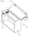
- Fig. 1 shows an embodiment of a cupboard-shaped piece of furniture 1 in a perspective view, wherein an actuator 4 according to the invention is provided for driving a highly movable flap 3.
- the actuator 4 is attached to the inside of opposite vertical side walls of the furniture body 2 respectively.
- at least one actuating arm 5 is provided, which is pivotally mounted on the one hand on a base body of the actuator 4 and on the other hand is hingedly connected to the flap 3.
- the flap 3 assumes a substantially vertical position in the closed end position.
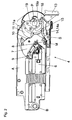
- Fig. 2 1 shows a side view of an exemplary embodiment of a steering drive 4.
- the actuator 4 comprises a spring device 6 which is movably mounted on the base body A at a pivot point B.
- the spring device 6 acts on an intermediate lever 7 mounted on the pivot point S, the engagement point 8 on the Intermediate lever 7 is displaceable via an adjusting device 9.
- changed leverage conditions result in addition to the changed preload the adjusting device 9, the acting torque to the actuator arm 5, not shown here are selectively adjusted according to the respective weight of the flap to be moved 3, so that the flap 3 is held automatically in any pivotal position against gravity automatically.
- a pressure roller 10 is mounted, which can run on a control contour 11a of a pivot point P mounted on the control cam 11 during the pivoting movement of the actuating arm 5.
- the in Fig. 1 shown actuator arm 5 for moving the flap 3 is connected via a coupling part 13 of the control cam 11 with this releasably connectable, preferably latched.
- An essential component of the subject invention forms a first locking element 14 in the form of a lever 14a, which is pivotally mounted on a rotation axis M.
- the lever 14a has a laterally projecting guide pin 15, which is slidably mounted during the pivoting movement of the actuating arm 5, not shown here along a arranged on the rotatable control cam 11, arcuate cam 16.
- control cam 16 has an approximately sawtooth or wave-shaped course
- the guide pin 15 lifts off by the formed by the sawtooth or wavy cam 16 peaks when exceeding a predetermined pivoting speed of the actuator arm 5 of the cam 16, whereby the lever 14a with its locking element 18 with a second locking element 19 - in particular with the toothing 19 a thereof - can be latched, so that the movement of the rotatable control cam 11 (and thus of the actuating arm 5) is stopped.
- the guide pin 15 of the lever 14 slides along the control cam 16, without significantly lifting. Consequently, no latching between the first locking element 14 and the second locking element 19 is produced at a low pivoting speed of the actuating arm 5.
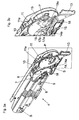
- Fig. 3a shows a perspective view of the actuator 4 according to Fig. 2
- Fig. 3b an enlarged view of the in Fig. 3a marked area illustrated.
- Fig. 3a shows a spring device 6 with parallel-connected compression springs, which acts on the point of application 8 a mounted about the rotation axis S intermediate lever 7.
- an adjusting device 9 is provided, through which the position of the point 8 on the intermediate lever 7 is variable.
- the intermediate lever 7 has a pressure roller 10 which can run during the pivotal movement of the actuating arm 5 on the control contour 11a of the control cam 11.
- the control contour 11a is formed in the exemplary embodiment shown by an outer peripheral surface of the control cam 11.
- a cover of the control cam 11 has been removed.
- the second locking element 19 supports with its teeth 19a.
- locking lever 14a with its integrally molded locking element 18, which has a plurality of locking teeth in the illustrated embodiment.
- the control cam 16 with an approximately sawtooth-shaped course, so that the laterally projecting guide pin 15 of the lever 14a can rise above the opening speed of the actuating arm 5 from the formed tips 17a, 17b, whereby the locking element 18 of the lever 14a with the teeth 19a of the second locking element 19 can be latched.
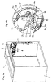
- Fig. 4a shows a perspective view of a piece of furniture 1 with a mounted on the furniture body 2 actuator 4, wherein the actuating arm 5 acting on the spring device 6, the intermediate lever 7 and the actuating arm 5 associated rotatable control cam 11 can be seen. If - as in Fig. 4a shown - no flap 3 is articulated on the actuator arm 5, the actuator arm 5 can rocket solid by the spring device 6 acted upon. To avoid this uncontrolled opening movement the mounting fuse is provided with the locking mechanism described. The guide pin 15 of the lever 14a is guided during the movement of the actuating arm 5 along a control cam 16 with tips 17a, 17b. If the control arm 5 is moved slowly and in a controlled manner, there is no latching between the lever 14a and the toothing 19a of the second locking element 19.
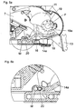
- Fig. 5a and Fig. 5b show Fig. 4a and Fig. 4b analogous representations with the difference that now the actuator arm 5 has been blocked in the course of its opening movement.
- a predetermined pivoting speed of Stellarmes 5 of the guide pin 15 of the pivotally mounted lever 14a jumps from the tips 17a, 17b, 17c of the control cam 16, whereby the locking teeth of the lever 14a with the teeth 19a of the second locking element 19 latch.
- the actuator arm 5 must be pressed by the user in the direction of the closed position, whereby the lever 14a releases again from the locking element 19 due to gravity.
- Fig. 6a shows a way to prevent accidental rebounding of the locking element 18 of the toothing 19a of the second locking element 19.
- the axis of rotation M of the lever 14a which is movably mounted within a slot guide.
- a damping element 20 is arranged, which is formed in the embodiment shown as a hard plastic.
- Fig. 6b shows an enlarged detail of the in Fig. 6a circled area. In the figure shown there is no blocking of the actuating arm 5.
- Fig. 7a and Fig. 7b show the embodiment according to the Fig. 6a and Fig. 6b , wherein a latching between the pivotally mounted lever 14a and the control point 11 mounted around the pivot point P is present. It is especially made Fig. 7b It can be seen that the damping element 20 was compressed hard plastic in this latched state. In this way, an unintentional rebound of the locking element 18 of the lever 14a of the teeth 19a of the second locking element 19 can be effectively prevented.
- the damping element 20 can also be replaced by at least one mechanical spring element, which allows a movable and damped mounting of the axis of rotation M of the lever 14a.
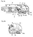
- Fig. 8a and the detailed presentation Fig. 8b show the kinematic reversal solution of the locking mechanism.
- the first locking element 14 is arranged in the form of the lever 14a with the axis of rotation M in the region of the rotatable control cam 11.
- the sawtooth-shaped control cam 16 is now arranged or formed on a preferably immovable part 21 on the main body A of the actuator 4.
- the guide pin 15 of the lever 14a slides in a controlled, slow movement in touching contact with the saw teeth of the cam 16.
- Fig. 9a and Fig. 9b the latched position of the lever 14a is shown, wherein the locking element 18 is in engagement with the counter-toothing of the stationary part 21.
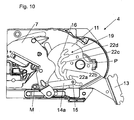
- Fig. 10 shows an alternative embodiment of an actuator 4.
- locking lever 14a which in turn is mounted at the pivot point M.
- a laterally projecting guide pin 15 is arranged, which is guided along the control cam 16, unless the critical pivoting speed of the actuating arm 5 is reached.
- the control cam 16 is formed as an integral part of the control cam 11.
- the control cam 16 can be punched out of the control cam 11 in a simple manner.
- the second locking element 19 is formed in the embodiment shown as a superimposed on the cam 16 locking curve. This locking curve has a plurality of deflections 22a-22d, in which the guide pin 15 can retract when exceeding the critical pivot speed, whereby the actuating arm 5 can be locked.
- Fig. 11a and the detailed representation according to Fig. 11b show an alternative embodiment of an actuator 4.
- a pure lever mechanism 24 for moving the actuator arm 5 is provided.
- the hinged at the pivot point B spring device 6 acted on the point 8 a mounted around the axis C, two-armed lever 23.
- the point 8 on the lever 23 is changed by the adjustment device 9.
- the lever 23 acts on a lever 23a a four-bar linkage.
- the four-bar linkage comprises articulated levers 25a and 25b, which are mounted at pivot points D and E. With both articulated arms 25a and 25b, a longitudinally extended main lever 26 is connected to the joint axes F and G.
- the longitudinally extended main lever 26 is moved out in the course of the opening movement and thereby displaced parallel to itself.
- the basic function of this actuator 4 is According to the prior art known and need not be described in detail at this point. It is essential that between the articulated lever 25b and the control lever 27, a locking element 14 is effective.
- the locking element 14 in the form of the lever 14 a is mounted on the pivot lever 25 b at the pivot point M. From the enlarged detail according to Fig. 11b is the guide pin 15 can be seen, which is feasible along a substantially sawtooth-shaped cam 16.
- the second locking element 19 is formed in the form of a latching cam with Dodge for the guide pin 15, in which the guide pin 15 can retract when exceeding the predetermined opening speed of the actuating arm 5, whereby the actuating arm 5 is latched in its relative position relative to the main body A of the actuator 4 ,
- the operating principle of the cam 16 with the superimposed latching cam and the Dodge 22a-22d is basically with the in Fig. 10 identical embodiment described.
- the present invention is not limited in principle to the illustrated embodiments, but includes and extends to all variants and technical equivalents that may fall within the scope of the following claims.
- the location information chosen in the description such as top, bottom, side, etc. based on the usual installation position of the components used as well as on the figure shown and are to be transferred to a new position in a change in position.
- the proposed mounting fuse is designed so that it works in each pivot position of the actuator 4 (also laterally and upside down). This is of considerable relevance, since the furniture body 2 is very often rotated or tilted with the actuator 4 pre-assembled in the course of the assembly process of the furniture 1. Since the furniture flap 3 is not hinged to the actuating arm 5 at this stage, the injury potential is considerable.
- the first locking element 14 may also have the shape of a hammer, wherein the main arm of the hammer is mounted on the rotation axis M and the two hammer ends on the one hand with the control cam 16 and on the other hand with the second locking member 19 can be brought into abutment.
- the arrangement of the guide pin 15 can be omitted.
Landscapes
- Engineering & Computer Science (AREA)
- Mechanical Engineering (AREA)
- Closing And Opening Devices For Wings, And Checks For Wings (AREA)
- Chairs For Special Purposes, Such As Reclining Chairs (AREA)
Applications Claiming Priority (2)
| Application Number | Priority Date | Filing Date | Title |
|---|---|---|---|
| AT3662008A AT506519B1 (de) | 2008-03-06 | 2008-03-06 | Stellantrieb für eine möbelklappe mit einer montagesicherung für den leeren stellarm |
| PCT/AT2009/000070 WO2009108971A1 (de) | 2008-03-06 | 2009-02-20 | Stellantrieb für eine möbelklappe mit einer montagesicherung für den leeren stellarm |
Publications (2)
| Publication Number | Publication Date |
|---|---|
| EP2247811A1 EP2247811A1 (de) | 2010-11-10 |
| EP2247811B1 true EP2247811B1 (de) | 2013-05-22 |
Family
ID=40636852
Family Applications (1)
| Application Number | Title | Priority Date | Filing Date |
|---|---|---|---|
| EP09716702.7A Active EP2247811B1 (de) | 2008-03-06 | 2009-02-20 | Stellentrieb für eine möbelklappe mit einer montagesicherung für den leeren stellarm |
Country Status (6)
| Country | Link |
|---|---|
| EP (1) | EP2247811B1 (es) |
| JP (1) | JP5524089B2 (es) |
| CN (1) | CN101952530B (es) |
| AT (1) | AT506519B1 (es) |
| ES (1) | ES2425375T3 (es) |
| WO (1) | WO2009108971A1 (es) |
Cited By (1)
| Publication number | Priority date | Publication date | Assignee | Title |
|---|---|---|---|---|
| WO2023046650A1 (de) * | 2021-09-27 | 2023-03-30 | ambigence GmbH & Co. KG | Möbelkomponente |
Families Citing this family (10)
| Publication number | Priority date | Publication date | Assignee | Title |
|---|---|---|---|---|
| AT508529A1 (de) * | 2009-07-28 | 2011-02-15 | Blum Gmbh Julius | Stellantrieb für ein bewegbares möbelteil |
| AT512156B1 (de) * | 2012-05-25 | 2013-06-15 | Blum Gmbh Julius | Anordnung zum Bewegen eines bewegbaren Möbelteils |
| AT16333U1 (de) * | 2016-03-11 | 2019-07-15 | Blum Gmbh Julius | Stellantrieb zum Antrieb eines bewegbar gelagerten Möbelteils |
| IT201700044196A1 (it) * | 2017-04-21 | 2018-10-21 | Effegi Brevetti Srl | Meccanismo di movimentazione di un’anta di mobile |
| DE102017114774A1 (de) * | 2017-07-03 | 2019-01-03 | Hettich-Oni Gmbh & Co. Kg | Klappenbeschlag und Möbel |
| CN107747446B (zh) * | 2017-11-17 | 2023-02-03 | 广东东泰五金精密制造有限公司 | 一种用于家具上翻折叠门的活动定位结构 |
| DE102018105116A1 (de) * | 2018-03-06 | 2019-09-12 | Hettich-Oni Gmbh & Co. Kg | Möbel und Verfahren zum Öffnen und Schließen einer verschwenkbaren Klappe |
| AT522109A1 (de) * | 2019-01-31 | 2020-08-15 | Blum Gmbh Julius | Stellantrieb zum Bewegen einer Möbelklappe |
| AT522458B1 (de) * | 2019-05-17 | 2020-11-15 | Blum Gmbh Julius | Möbelbeschlag |
| AT523757B1 (de) * | 2020-05-07 | 2023-07-15 | Blum Gmbh Julius | Möbelantrieb |
Family Cites Families (6)
| Publication number | Priority date | Publication date | Assignee | Title |
|---|---|---|---|---|
| CH555063A (es) * | 1973-08-24 | 1974-10-15 | ||
| CH573146A5 (en) * | 1974-07-18 | 1976-02-27 | Kauffmann Th Kg Rolladen Kauff | Grab for lifting or lowering loads - released in dependence on speed with control disc rotating with drive roller |
| DE10223026C5 (de) * | 2002-05-22 | 2007-11-08 | Huwil-Werke Gmbh Möbelschloss- Und Beschlagfabriken | Deckelsteller |
| AT7500U1 (de) * | 2004-02-09 | 2005-04-25 | Blum Gmbh Julius | Stellarmantrieb für klappen von schränken |
| DE502005009925D1 (de) * | 2004-07-14 | 2010-08-26 | Blum Gmbh Julius | Stellmechanismus für einen schwenkbar gelagerten Stellarm |
| AT502941B1 (de) * | 2004-12-28 | 2011-05-15 | Blum Gmbh Julius | Stellantrieb zum antrieb einer klappe eines möbels |
-
2008
- 2008-03-06 AT AT3662008A patent/AT506519B1/de not_active IP Right Cessation
-
2009
- 2009-02-20 CN CN200980106153.1A patent/CN101952530B/zh active Active
- 2009-02-20 ES ES09716702T patent/ES2425375T3/es active Active
- 2009-02-20 EP EP09716702.7A patent/EP2247811B1/de active Active
- 2009-02-20 JP JP2010548984A patent/JP5524089B2/ja active Active
- 2009-02-20 WO PCT/AT2009/000070 patent/WO2009108971A1/de active Application Filing
Cited By (1)
| Publication number | Priority date | Publication date | Assignee | Title |
|---|---|---|---|---|
| WO2023046650A1 (de) * | 2021-09-27 | 2023-03-30 | ambigence GmbH & Co. KG | Möbelkomponente |
Also Published As
| Publication number | Publication date |
|---|---|
| ES2425375T3 (es) | 2013-10-15 |
| CN101952530B (zh) | 2013-09-18 |
| JP5524089B2 (ja) | 2014-06-18 |
| EP2247811A1 (de) | 2010-11-10 |
| CN101952530A (zh) | 2011-01-19 |
| JP2011514457A (ja) | 2011-05-06 |
| AT506519B1 (de) | 2012-10-15 |
| AT506519A1 (de) | 2009-09-15 |
| WO2009108971A1 (de) | 2009-09-11 |
Similar Documents
| Publication | Publication Date | Title |
|---|---|---|
| EP2247811B1 (de) | Stellentrieb für eine möbelklappe mit einer montagesicherung für den leeren stellarm | |
| EP2609271B1 (de) | Dämpfvorrichtung für möbelteile | |
| EP3475507B1 (de) | Stellantrieb für möbelteile | |
| EP2260166B1 (de) | DÄMPFVORRICHTUNG ZUR DÄMPFUNG EINER ÖFFNUNGS- UND/ODER SCHLIEßBEWEGUNG EINES MÖBELBESCHLAGES | |
| EP2129852B1 (de) | Mehrgelenkscharnier | |
| EP2855813B1 (de) | Anordnung zum bewegen eines bewegbaren möbelteils | |
| EP2649261B1 (de) | SCHLIEß- UND DÄMPFUNGSVORRICHTUNG FÜR BEWEGBARE MÖBELTEILE | |
| EP2347076B1 (de) | Stellantrieb für bewegbare möbelteile | |
| DE10314180A1 (de) | Reversierbarer Fußgängerschutz-Aktuator | |
| WO2014146914A1 (de) | Luftausströmer | |
| EP2096027A2 (de) | Klappensteuerung | |
| AT508176B1 (de) | Klemmschutzvorrichtung für ein möbelscharnier | |
| DE102012112084A1 (de) | Türschließer mit verstellbarer Federeinheit | |
| EP3737816B1 (de) | Möbelscharnier, möbelplatte und möbelkorpus | |
| DE202006020216U1 (de) | Stellarm für Möbelklappen | |
| EP4244456B1 (de) | Möbelbeschlag zur bewegbaren lagerung eines möbelteiles | |
| DE102009057214A1 (de) | Türfeststeller für eine Tür eines Kraftwagens und Lagerung für eine Tür eines Kraftwagens mit einem Türfeststeller | |
| DE102016100606B3 (de) | Deckelsteller | |
| EP2949848A1 (de) | Vorrichtung zum bewegen einer an einem möbelkorpus bewegbar aufgenommenen faltklappe sowie möbel mit einer solchen vorrichtung | |
| EP1957739B1 (de) | Kantenschutzvorrichtung | |
| DE19836049B4 (de) | Sicherheitseinrichtung für einen Flügel eines Fensters | |
| DE102017211924A1 (de) | Gelenkanordnung mit richtungsabhängigem Schwenkwiderstand | |
| DE102020215389B3 (de) | Hebelgetriebe für einen Radwindabweiser sowie Verfahren zum Betrieb eines Hebelgetriebes mit Überlastschutz | |
| DE102017110498A1 (de) | Hubmechanismus einer Ablage eines Möbels oder Haushaltsgerätes, Möbel oder Haushaltsgerät und Schubkasten | |
| EP3396099B1 (de) | Dichtungsvorrichtung |
Legal Events
| Date | Code | Title | Description |
|---|---|---|---|
| PUAI | Public reference made under article 153(3) epc to a published international application that has entered the european phase |
Free format text: ORIGINAL CODE: 0009012 |
|
| 17P | Request for examination filed |
Effective date: 20100712 |
|
| AK | Designated contracting states |
Kind code of ref document: A1 Designated state(s): AT BE BG CH CY CZ DE DK EE ES FI FR GB GR HR HU IE IS IT LI LT LU LV MC MK MT NL NO PL PT RO SE SI SK TR |
|
| AX | Request for extension of the european patent |
Extension state: AL BA RS |
|
| DAX | Request for extension of the european patent (deleted) | ||
| REG | Reference to a national code |
Ref country code: DE Ref legal event code: R079 Ref document number: 502009007159 Country of ref document: DE Free format text: PREVIOUS MAIN CLASS: E05F0001100000 Ipc: E05D0015260000 |
|
| RIC1 | Information provided on ipc code assigned before grant |
Ipc: E05D 15/26 20060101AFI20121211BHEP Ipc: E05D 15/40 20060101ALI20121211BHEP Ipc: E05F 1/10 20060101ALI20121211BHEP |
|
| GRAP | Despatch of communication of intention to grant a patent |
Free format text: ORIGINAL CODE: EPIDOSNIGR1 |
|
| GRAS | Grant fee paid |
Free format text: ORIGINAL CODE: EPIDOSNIGR3 |
|
| GRAA | (expected) grant |
Free format text: ORIGINAL CODE: 0009210 |
|
| AK | Designated contracting states |
Kind code of ref document: B1 Designated state(s): AT BE BG CH CY CZ DE DK EE ES FI FR GB GR HR HU IE IS IT LI LT LU LV MC MK MT NL NO PL PT RO SE SI SK TR |
|
| REG | Reference to a national code |
Ref country code: GB Ref legal event code: FG4D Free format text: NOT ENGLISH |
|
| REG | Reference to a national code |
Ref country code: CH Ref legal event code: EP |
|
| REG | Reference to a national code |
Ref country code: AT Ref legal event code: REF Ref document number: 613340 Country of ref document: AT Kind code of ref document: T Effective date: 20130615 |
|
| REG | Reference to a national code |
Ref country code: IE Ref legal event code: FG4D Free format text: LANGUAGE OF EP DOCUMENT: GERMAN |
|
| REG | Reference to a national code |
Ref country code: DE Ref legal event code: R096 Ref document number: 502009007159 Country of ref document: DE Effective date: 20130718 |
|
| REG | Reference to a national code |
Ref country code: ES Ref legal event code: FG2A Ref document number: 2425375 Country of ref document: ES Kind code of ref document: T3 Effective date: 20131015 |
|
| REG | Reference to a national code |
Ref country code: LT Ref legal event code: MG4D |
|
| PG25 | Lapsed in a contracting state [announced via postgrant information from national office to epo] |
Ref country code: FI Free format text: LAPSE BECAUSE OF FAILURE TO SUBMIT A TRANSLATION OF THE DESCRIPTION OR TO PAY THE FEE WITHIN THE PRESCRIBED TIME-LIMIT Effective date: 20130522 Ref country code: PT Free format text: LAPSE BECAUSE OF FAILURE TO SUBMIT A TRANSLATION OF THE DESCRIPTION OR TO PAY THE FEE WITHIN THE PRESCRIBED TIME-LIMIT Effective date: 20130923 Ref country code: SE Free format text: LAPSE BECAUSE OF FAILURE TO SUBMIT A TRANSLATION OF THE DESCRIPTION OR TO PAY THE FEE WITHIN THE PRESCRIBED TIME-LIMIT Effective date: 20130522 Ref country code: GR Free format text: LAPSE BECAUSE OF FAILURE TO SUBMIT A TRANSLATION OF THE DESCRIPTION OR TO PAY THE FEE WITHIN THE PRESCRIBED TIME-LIMIT Effective date: 20130823 Ref country code: NO Free format text: LAPSE BECAUSE OF FAILURE TO SUBMIT A TRANSLATION OF THE DESCRIPTION OR TO PAY THE FEE WITHIN THE PRESCRIBED TIME-LIMIT Effective date: 20130822 Ref country code: IS Free format text: LAPSE BECAUSE OF FAILURE TO SUBMIT A TRANSLATION OF THE DESCRIPTION OR TO PAY THE FEE WITHIN THE PRESCRIBED TIME-LIMIT Effective date: 20130922 Ref country code: SI Free format text: LAPSE BECAUSE OF FAILURE TO SUBMIT A TRANSLATION OF THE DESCRIPTION OR TO PAY THE FEE WITHIN THE PRESCRIBED TIME-LIMIT Effective date: 20130522 Ref country code: LT Free format text: LAPSE BECAUSE OF FAILURE TO SUBMIT A TRANSLATION OF THE DESCRIPTION OR TO PAY THE FEE WITHIN THE PRESCRIBED TIME-LIMIT Effective date: 20130522 |
|
| REG | Reference to a national code |
Ref country code: NL Ref legal event code: VDEP Effective date: 20130522 |
|
| PG25 | Lapsed in a contracting state [announced via postgrant information from national office to epo] |
Ref country code: PL Free format text: LAPSE BECAUSE OF FAILURE TO SUBMIT A TRANSLATION OF THE DESCRIPTION OR TO PAY THE FEE WITHIN THE PRESCRIBED TIME-LIMIT Effective date: 20130522 Ref country code: BG Free format text: LAPSE BECAUSE OF FAILURE TO SUBMIT A TRANSLATION OF THE DESCRIPTION OR TO PAY THE FEE WITHIN THE PRESCRIBED TIME-LIMIT Effective date: 20130822 Ref country code: HR Free format text: LAPSE BECAUSE OF FAILURE TO SUBMIT A TRANSLATION OF THE DESCRIPTION OR TO PAY THE FEE WITHIN THE PRESCRIBED TIME-LIMIT Effective date: 20130522 |
|
| PG25 | Lapsed in a contracting state [announced via postgrant information from national office to epo] |
Ref country code: LV Free format text: LAPSE BECAUSE OF FAILURE TO SUBMIT A TRANSLATION OF THE DESCRIPTION OR TO PAY THE FEE WITHIN THE PRESCRIBED TIME-LIMIT Effective date: 20130522 |
|
| PG25 | Lapsed in a contracting state [announced via postgrant information from national office to epo] |
Ref country code: CZ Free format text: LAPSE BECAUSE OF FAILURE TO SUBMIT A TRANSLATION OF THE DESCRIPTION OR TO PAY THE FEE WITHIN THE PRESCRIBED TIME-LIMIT Effective date: 20130522 Ref country code: DK Free format text: LAPSE BECAUSE OF FAILURE TO SUBMIT A TRANSLATION OF THE DESCRIPTION OR TO PAY THE FEE WITHIN THE PRESCRIBED TIME-LIMIT Effective date: 20130522 Ref country code: EE Free format text: LAPSE BECAUSE OF FAILURE TO SUBMIT A TRANSLATION OF THE DESCRIPTION OR TO PAY THE FEE WITHIN THE PRESCRIBED TIME-LIMIT Effective date: 20130522 Ref country code: SK Free format text: LAPSE BECAUSE OF FAILURE TO SUBMIT A TRANSLATION OF THE DESCRIPTION OR TO PAY THE FEE WITHIN THE PRESCRIBED TIME-LIMIT Effective date: 20130522 |
|
| PG25 | Lapsed in a contracting state [announced via postgrant information from national office to epo] |
Ref country code: RO Free format text: LAPSE BECAUSE OF FAILURE TO SUBMIT A TRANSLATION OF THE DESCRIPTION OR TO PAY THE FEE WITHIN THE PRESCRIBED TIME-LIMIT Effective date: 20130522 Ref country code: NL Free format text: LAPSE BECAUSE OF FAILURE TO SUBMIT A TRANSLATION OF THE DESCRIPTION OR TO PAY THE FEE WITHIN THE PRESCRIBED TIME-LIMIT Effective date: 20130522 |
|
| PLBE | No opposition filed within time limit |
Free format text: ORIGINAL CODE: 0009261 |
|
| STAA | Information on the status of an ep patent application or granted ep patent |
Free format text: STATUS: NO OPPOSITION FILED WITHIN TIME LIMIT |
|
| REG | Reference to a national code |
Ref country code: HU Ref legal event code: AG4A Ref document number: E018950 Country of ref document: HU |
|
| 26N | No opposition filed |
Effective date: 20140225 |
|
| REG | Reference to a national code |
Ref country code: DE Ref legal event code: R097 Ref document number: 502009007159 Country of ref document: DE Effective date: 20140225 |
|
| BERE | Be: lapsed |
Owner name: JULIUS BLUM GMBH Effective date: 20140228 |
|
| PG25 | Lapsed in a contracting state [announced via postgrant information from national office to epo] |
Ref country code: LU Free format text: LAPSE BECAUSE OF FAILURE TO SUBMIT A TRANSLATION OF THE DESCRIPTION OR TO PAY THE FEE WITHIN THE PRESCRIBED TIME-LIMIT Effective date: 20140220 Ref country code: MC Free format text: LAPSE BECAUSE OF FAILURE TO SUBMIT A TRANSLATION OF THE DESCRIPTION OR TO PAY THE FEE WITHIN THE PRESCRIBED TIME-LIMIT Effective date: 20130522 |
|
| REG | Reference to a national code |
Ref country code: CH Ref legal event code: PL |
|
| GBPC | Gb: european patent ceased through non-payment of renewal fee |
Effective date: 20140220 |
|
| PG25 | Lapsed in a contracting state [announced via postgrant information from national office to epo] |
Ref country code: CH Free format text: LAPSE BECAUSE OF NON-PAYMENT OF DUE FEES Effective date: 20140228 Ref country code: LI Free format text: LAPSE BECAUSE OF NON-PAYMENT OF DUE FEES Effective date: 20140228 |
|
| REG | Reference to a national code |
Ref country code: FR Ref legal event code: ST Effective date: 20141031 |
|
| REG | Reference to a national code |
Ref country code: IE Ref legal event code: MM4A |
|
| PG25 | Lapsed in a contracting state [announced via postgrant information from national office to epo] |
Ref country code: BE Free format text: LAPSE BECAUSE OF NON-PAYMENT OF DUE FEES Effective date: 20140228 Ref country code: GB Free format text: LAPSE BECAUSE OF NON-PAYMENT OF DUE FEES Effective date: 20140220 Ref country code: IE Free format text: LAPSE BECAUSE OF NON-PAYMENT OF DUE FEES Effective date: 20140220 Ref country code: FR Free format text: LAPSE BECAUSE OF NON-PAYMENT OF DUE FEES Effective date: 20140228 |
|
| PG25 | Lapsed in a contracting state [announced via postgrant information from national office to epo] |
Ref country code: MT Free format text: LAPSE BECAUSE OF FAILURE TO SUBMIT A TRANSLATION OF THE DESCRIPTION OR TO PAY THE FEE WITHIN THE PRESCRIBED TIME-LIMIT Effective date: 20130522 |
|
| PG25 | Lapsed in a contracting state [announced via postgrant information from national office to epo] |
Ref country code: CY Free format text: LAPSE BECAUSE OF FAILURE TO SUBMIT A TRANSLATION OF THE DESCRIPTION OR TO PAY THE FEE WITHIN THE PRESCRIBED TIME-LIMIT Effective date: 20130522 |
|
| PG25 | Lapsed in a contracting state [announced via postgrant information from national office to epo] |
Ref country code: MK Free format text: LAPSE BECAUSE OF FAILURE TO SUBMIT A TRANSLATION OF THE DESCRIPTION OR TO PAY THE FEE WITHIN THE PRESCRIBED TIME-LIMIT Effective date: 20130522 |
|
| PGFP | Annual fee paid to national office [announced via postgrant information from national office to epo] |
Ref country code: TR Payment date: 20230201 Year of fee payment: 15 Ref country code: IT Payment date: 20230220 Year of fee payment: 15 |
|
| P01 | Opt-out of the competence of the unified patent court (upc) registered |
Effective date: 20230523 |
|
| PGFP | Annual fee paid to national office [announced via postgrant information from national office to epo] |
Ref country code: ES Payment date: 20240307 Year of fee payment: 16 |
|
| PGFP | Annual fee paid to national office [announced via postgrant information from national office to epo] |
Ref country code: AT Payment date: 20240228 Year of fee payment: 16 |
|
| PGFP | Annual fee paid to national office [announced via postgrant information from national office to epo] |
Ref country code: HU Payment date: 20240124 Year of fee payment: 16 Ref country code: DE Payment date: 20240228 Year of fee payment: 16 |